US6891887B1 - Multi-carrier LAN adapter device using interpolative equalizer - Google Patents
Multi-carrier LAN adapter device using interpolative equalizerDownload PDFInfo
- Publication number
- US6891887B1 US6891887B1US09/885,220US88522001AUS6891887B1US 6891887 B1US6891887 B1US 6891887B1US 88522001 AUS88522001 AUS 88522001AUS 6891887 B1US6891887 B1US 6891887B1
- Authority
- US
- United States
- Prior art keywords
- equalizer
- lan
- data
- carrier
- frequency domain
- Prior art date
- Legal status (The legal status is an assumption and is not a legal conclusion. Google has not performed a legal analysis and makes no representation as to the accuracy of the status listed.)
- Expired - Fee Related, expires
Links
Images


Classifications
- H—ELECTRICITY
- H04—ELECTRIC COMMUNICATION TECHNIQUE
- H04L—TRANSMISSION OF DIGITAL INFORMATION, e.g. TELEGRAPHIC COMMUNICATION
- H04L25/00—Baseband systems
- H04L25/02—Details ; arrangements for supplying electrical power along data transmission lines
- H04L25/0202—Channel estimation
- H04L25/0224—Channel estimation using sounding signals
- H04L25/0228—Channel estimation using sounding signals with direct estimation from sounding signals
- H04L25/023—Channel estimation using sounding signals with direct estimation from sounding signals with extension to other symbols
- H04L25/0232—Channel estimation using sounding signals with direct estimation from sounding signals with extension to other symbols by interpolation between sounding signals
- H—ELECTRICITY
- H04—ELECTRIC COMMUNICATION TECHNIQUE
- H04L—TRANSMISSION OF DIGITAL INFORMATION, e.g. TELEGRAPHIC COMMUNICATION
- H04L25/00—Baseband systems
- H04L25/02—Details ; arrangements for supplying electrical power along data transmission lines
- H04L25/0202—Channel estimation
- H04L25/022—Channel estimation of frequency response
- H—ELECTRICITY
- H04—ELECTRIC COMMUNICATION TECHNIQUE
- H04L—TRANSMISSION OF DIGITAL INFORMATION, e.g. TELEGRAPHIC COMMUNICATION
- H04L27/00—Modulated-carrier systems
- H04L27/26—Systems using multi-frequency codes
- H04L27/2601—Multicarrier modulation systems
- H04L27/2647—Arrangements specific to the receiver only
- H—ELECTRICITY
- H04—ELECTRIC COMMUNICATION TECHNIQUE
- H04L—TRANSMISSION OF DIGITAL INFORMATION, e.g. TELEGRAPHIC COMMUNICATION
- H04L25/00—Baseband systems
- H04L25/02—Details ; arrangements for supplying electrical power along data transmission lines
- H04L25/03—Shaping networks in transmitter or receiver, e.g. adaptive shaping networks
- H04L25/03006—Arrangements for removing intersymbol interference
- H04L25/03159—Arrangements for removing intersymbol interference operating in the frequency domain
Definitions
- the present inventionrelates to Local Area Networks (LANs). More particularly, the invention relates to a LAN architecture specifically designed to be operated within a home environment, but may also be used in a small business setting.
- Home LANsmay be used to connect computers, peripherals, TVs, and audio equipment, as well as less intelligent devices (appliances, thermostats, etc.), and provide connectivity to devices and networks outside the home (e.g., Internet and corporate LANs).
- Networksare collections of independent computers that communicate with one another over a shared physical connection, or network medium. Networks are often categorized as Local Area Networks (LAN) and Wide Area Networks (WAN).
- LANLocal Area Networks
- WANWide Area Networks
- Local area networksare usually confined to a specific geographic area, such as an office building.
- LANsare not necessarily simple in design, and may link together hundreds of computers.
- the development of various standards for networking protocolshas made possible the proliferation of LANs in organizations worldwide for business and educational applications.
- Ethernetis a LAN networking protocol commonly utilized today. Ethernet typically utilizes a “star” or “spoke” topology, where each computer of the LAN is connected to other computers via a central hub. In such a configuration, each computer has its own private connection to the LAN and can be disconnected from the network without interfering with any other computer's connection.
- Ethernet LAN technologywas standardized by the Institute of Electrical and Electronics Engineers (IEEE) as the 802.3 specification entitled “Carrier Sense Multiple Access with Collision Detection (CSMA/CD) Access Method and Physical Layer Specifications.” Initially, Ethernet technology used coaxial cable in a bus topology, however it has evolved to take into advantage of new technologies such as twisted pair cabling (10 Base-T), fiber optics (10 Base-FL), and 100 Mbps operation (100 Base-X, or Fast Ethernet). The current standard is known as IEEE 802.3u, the contents of which are hereby incorporated by reference.
- 10/100 Base-Tis the requirement for “home run” cabling, i.e., each device is connected back to a central hub, as opposed to “daisy chain” connections.
- the Ethernet systemconsists of three basic elements: the physical medium; medium access control rules; and a packet format.
- the physical mediumis used to convey Ethernet signals from one computer to another.
- the medium access control rulesare embedded in each Ethernet interface, and allow multiple computers to access the shared Ethernet channel.
- the Ethernet packet, or frameconsists of a standardized set of fields used to carry data over the system.
- WANWide Area Networks
- the interconnectionsare performed via services such as dedicated leased phone lines, digital subscriber lines, dial-up phone lines, satellite links, and data packet carrier services.
- Wide area networkingcan be as simple as providing modems and a remote access server to allow remote users to dial in; or it can be as complex as linking hundreds of branch offices across the world using special routing protocols.
- Once type of WAN interconnection mechanismis Asymmetric Digital Subscriber Line.
- Asymmetric Digital Subscriber Lineis a communication system that operates over existing twisted-pair telephone lines between a central office and a residential or business location. It is generally a point-to-point connection between two dedicated devices, as opposed to multi-point, where numerous devices share the same physical medium.
- ADSLsupports bit transmission rates of up to approximately 6 Mbps in the downstream direction (to a subscriber device at the home), but only 640 Kbps in the upstream direction (to the service provider/central office).
- ADSL connectionsactually have three separate information channels: two data channels and a POTS channel.
- the first data channelis a high-speed downstream channel used to convey information to the subscriber. Its data rate is adaptable and ranges from 1.5 to 6.1 Mbps.
- the second data channelis a medium speed duplex channel providing bi-directional communication between the subscriber and the service provider/central office. Its rate is also adaptable and the rates range from 16 to 640 kbps.
- the third information channelis a POTS (Plain Old Telephone Service) channel.
- the POTS channelis typically not processed directly by the ADSL modems—the POTS channel operates in the standard POTS frequency range and is processed by standard POTS devices after being split from the ADSL signal.
- the American National Standards Institute (ANSI) Standard T1.413specifies an ADSL standard that is widely followed in the telecommunications industry.
- the ADSL standardspecifies a modulation technique known as Discrete Multi-Tone modulation.
- Discrete Multi-Toneuses a large number of subcarriers spaced close together. Each subcarrier is modulated using a type of Quadrature Amplitude Modulation (QAM). Alternative types of modulation include Multiple Phase Shift Keying (MPSK), including BPSK and QPSK, and Differential Phase Shift Keying (DPSK).
- MPSKMultiple Phase Shift Keying
- BPSKBPSK and QPSK
- DPSKDifferential Phase Shift Keying
- the data bitsare mapped to a series of symbols in the I-Q complex plane, and each symbol is used to modulate the amplitude and phase of one of the multiple tones, or carriers.
- the symbolsare used to specify the magnitude and phase of a subcarrier, where each subcarrier frequency corresponds to the center frequency of the “bin” associated with a Discrete Fourier Transform (DFT).
- DFTDiscrete Fourier Transform
- the modulated time-domain signal corresponding to all of the subcarrierscan then be
- the symbol periodis relatively long compared to single carrier systems because the bandwidth available to each carrier is restricted. However, a large number of symbols is transmitted simultaneously, one on each subcarrier.
- the number of discrete signal points that may be distinguished on a single carrieris a function of the noise level.
- the signal set, or constellation, of each subcarrieris determined based on the noise level within the relevant subcarrier frequency band.
- each carrierhas a narrow bandwidth, the channel impulse response is relatively flat across each subcarrier frequency band.
- the DMT standard for ADSL, ANSI T1.413specifies 256 subcarriers, each with a 4 kHz bandwidth. Each sub-carrier can be independently modulated from zero to a maximum of 15 bits/sec/Hz. This allows up to 60 kbps per tone. DMT transmission allows modulation and coding techniques to be employed independently for each of the sub-channels.
- the sub-channelsoverlap spectrally, but as a consequence of the orthogonality of the transform, if the distortion in the channel is mild relative to the bandwidth of a sub-channel, the data in each sub-channel can be demodulated with a small amount of interference from the other sub-channels.
- a cyclic-prefixat the beginning, or a periodic extension appended at the end of each symbol to maintain orthogonality. Because of the periodic nature of the FFT, no discontinuity in the time-domain channel is generated between the symbol and the extension. It has been shown that if the channel impulse response is shorter than the length of the periodic extension, sub-channel isolation is achieved.
- Plain Ordinary Telephone Serviceoperates over numerous types of existing wiring layouts.
- the topologyis a star configuration, combined with daisy chained connections for some phones.
- the type of wiringis also random—twisted pair, untwisted, various gauges, various numbers of wires (with possible cross-talk)—which creates a wide variation in the channel characteristics.
- the topologychanges from time to time as phones are connected, disconnected, etc.
- signals associated with the analog phone serviceinclude 48 vdc, and 100 volt ring signals. Ring signals are not zero-crossing switched, so high-frequency noise is produced. Any system operating over existing telephone wiring must contend with this environment.
- a LAN Adapter device having an interpolative equalizeris provided.
- the LAN adapter devicesallow LAN computing devices to connect to the LAN medium.
- the adapter devicesare internal or external to the LAN devices and provide a transceiver and protocol stacks for the LAN devices to communicate with each other.
- the physical layer of the transceiversincludes transmitter having a DMT modulator and demodulator that is dynamically configurable with respect to data rate and spectrum usage.
- Within the receiveris an equalizer for equalizing the received signal with a simple yet effective equalizer training method, thereby obviating the need for extensive equalizer training and long-term coefficient storage.
- the equalizertrains on known symbols transmitted on specific carriers that are spaced apart in the frequency domain and then determines the channel response at those frequencies.
- the remaining carriers that are modulated with dataare equalized based on an estimate of the channel response determined from interpolating between the points previously determined from the known symbols.
- FIG. 1depicts a preferred embodiment of the communication system
- FIG. 2shows a preferred embodiment of the protocol stacks within the gateway and the DMT LAN devices
- FIG. 3shows a preferred embodiment of the simplified protocol stacks within the gateway device
- FIG. 4is a block diagram of a preferred embodiment of the transceiver
- FIG. 5shows the DMT LAN
- FIG. 6shows a representative modulation signal point constellation
- FIG. 7depicts transmit data
- FIG. 8shows a correlation signal at the receive correlator
- FIG. 9shows the equalizer
- the system described herein, depicted in FIG. 1consists of two major components: the DMT LAN 20 and the DMT LAN gateway 100 that is connected between the DMT LAN 20 and the access infrastructure 10 .
- the access infrastructure 10includes the voice and data carrier networks as well as connections to the access points.
- the physical connection 80 to infrastructure 10may be a standard land-line connection over twisted pair cable or may be a wireless service to the gateway 100 .
- the gateway 100includes an infrastructure protocol stack 40 that communicates via physical connection 80 to the access infrastructure 10 and to the network 90 .
- the gateway 100also includes a DMT LAN protocol stack 50 that communicates with the DMT LAN 20 , and a forwarder 60 that bridges the top layers of these two stacks.
- the DMT LAN 20includes a plurality of devices similar to DMT LAN device 70 depicted in FIG. 1 .
- the DMT LAN device 70may also be referred to herein as a client device, or a node.
- the DMT LAN devices connected to the DMT LAN 20may include computers, computer peripherals such as printers and modems, copiers, fax machines and personal digital assistants. Also suitable for connection are TVs, audio-visual equipment, security systems, as well as less intelligent devices such as appliances, thermostats, and lighting fixtures. Less intelligent devices may have a simplified transceiver, or may be connected to the DMT LAN 20 via a separate control device or bridge.
- the DMT LAN medium, or physical electrical connection between devices,is preferably standard residential telephone wiring—typically pairs of twisted wires.
- the preferred embodiment of the gateway 100including forwarder 60 , is shown in FIG. 2 . It includes a DMT LAN adapter 74 having a transceiver 400 within the physical layer 262 , and a second transceiver to implement the physical layer of access infrastructure stack 40 for communication with the access infrastructure 10 .
- the second transceiverutilizes one of a number of communication protocols, such as those generally referred to as xDSL (e.g., ADSL, HDSL, etc.), simplified DSL known as DSL Lite or G.Lite, ISDN, cable modems, and the like.
- connection 200may only be included under certain circumstances, depending on the type of link from gateway 100 to access infrastructure 10 .
- Many servicessuch as ADSL require a point to point link and require relatively high line quality. In such a case, no other devices may be directly connected over the same medium.
- Link 200must be therefore be omitted to keep LAN devices 70 isolated from the access infrastructure link.
- Other transmission technologiesare more flexible and will operate over a physical medium having numerous wiring segments, some of which may be unterminated.
- both stacks 40 and 50 of gateway 100may be connected to the shared medium over a single electrical connection, as opposed to the two separate connections as actually depicted in FIGS. 1 and 2 .
- link 202connects LAN stack 50 and infrastructure stack 40 internal to the gateway device 100 , which is in turn connected to the shared LAN medium, while the access infrastructure is also connected directly to the shared LAN medium.
- link 200or its equivalent
- the operating frequency range of devices 70 on LAN 20must adapted so as not to interfere with communication between the gateway 100 and the access infrastructure 10 .
- the forwarder 60is a multi-point forwarder that runs a single-PPP-session module 224 to provide the necessary routing functionality for multi-point connectivity between devices 70 in the DMT LAN 20 and the external WAN environment 90 .
- the multi-point forwarder 60includes a name address translation protocol module 212 that allows a single PPP session (i.e., a single Internet IP address) to serve multiple DMT LAN devices 70 , each having separate IP addresses on the local DMT LAN 20 .
- a name address translation protocol module 212that allows a single PPP session (i.e., a single Internet IP address) to serve multiple DMT LAN devices 70 , each having separate IP addresses on the local DMT LAN 20 .
- FIG. 2shows the protocol layers and the multi-point forwarder 60 that supports multiple IP sessions on behalf of the DMT LAN devices 70 with just one PPP session terminated in module 224 of the forwarder 60 .
- Any client device 70may initiate the session, and it remains active until terminated. Termination may either be manual or automatic (timed).
- the PPP session modulesupports external network access for the local DMT LAN devices 70 .
- a Network Address Translation (NAT) module 212runs NAT services in an upper layer of the multi-point forwarder 60 thereby allowing a port number to be associated with the client's local IP address.
- NAT module 212makes devices on the DMT LAN 20 appear as a single IP address, thus allowing the devices to communicate with external networks 90 , including, for example, the Internet.
- NATNetwork Address Translation
- the DMT LAN 20uses private addressing.
- a device 70which is known locally by its private address, desires to communicate with a device on network 90 , it sends the request to gateway 100 .
- forwarder 60translates the private address to a common IP address assigned to gateway 100 . Further details of NAT are disclosed in U.S. patent application Ser. No. 09/035,600, filed Mar. 5, 1998, entitled Method and Protocol for Distributed Network Address Translation, the contents of which are hereby incorporated herein by reference. All remote access is therefore handled via the multi-point forwarder's 60 PPP module 224 .
- the multi-point forwarder 60includes a routing module 210 utilizing dynamic host configuration protocol (DHCP) and management module 220 (MNGT), which implements management functionality via, e.g., an SNMP agent, and a PPP module 224 for PPP session management.
- a PPP sessioncan be initiated by any local device's 70 request for remote access (e.g., a Web browser).
- the multi-point forwarder 60also provides session authentication and security 216 (AUTH).
- the routing module 210enables local IP addresses to be assigned to any local client device 70 .
- Network address translator 212allows the single PPP session to provide remote connectivity to any number of client devices 70 simultaneously.
- Additional services in the multi-point forwarder 60include a domain name server 214 (DNS), firewall 218 (FW), and a simple client agent 222 (SCA).
- DNSdomain name server
- FWfirewall 218
- SCAsimple client agent 222
- the SCA serviceallows simple clients, which do not have full TCP/IP capabilities, to send and receive IP data.
- the SCA 222does the additional protocol processing on behalf of the simple client.
- the multi-point forwarder 60communicates with client devices 70 by way of network adapters 74 .
- the adapters 74include MAC resolution layer 260 and physical layer 262 , which is a multi-carrier transceiver that operates in half-duplex mode. That is, one adapter 74 at a time transmits data to other adapters 74 on the DMT LAN 20 . Other devices 70 then take turns transmitting via adapters 74 as determined by the MAC protocol layer 260 as described herein.
- Adapter devices 74preferably support both high-speed devices or Full-Rate Device (FRD), and low-speed devices or Sub-Rate Devices (SRD) on the single DMT LAN medium.
- FFDFull-Rate Device
- SRDSub-Rate Devices
- the adapter device 74also provides the bottom layers of the protocol stack for communication on the DMT LAN-side of the gateway 100 .
- the top layers of the stacktypically run on a computing device, rather than the internal (or external) DMT LAN adapter, and ultimately terminate in applications running on a computer, or on a slow-speed SRD client.
- Existing host computersmay require a minimal high-level configuration modification (e.g., via a standard operating system configuration tool) in order to bypass local PPP management because this functionality preferably resides in the gateway's 100 multi-point forwarder 60 .
- the MAC layer 260 and the physical layer 262are implemented in all adapter devices. Data delivered down to the MAC layer are tagged with source and destination MAC addresses and priority. Data arriving to the physical layer 262 from the medium are passed to the MAC layer 260 for processing. All devices decode the destination address of incoming data and discard frames that do not correspond to their own MAC address. Any client device 70 connected to the DMT LAN network (via an adapter) can communicate with any other similarly connected device 70 , or with the gateway 100 .
- the internal adapter 74 shown in FIGS. 2 and 3provides the MAC layer 260 and physical layer 262 preferably in an application specific integrated circuit, or ASIC.
- the adaptermay alternatively be configured to provide higher level protocol processing, but the LAN device 70 preferably provides the layers above the MAC layer 260 .
- an address resolution protocol (ARP) module 256is layered above the MAC layer 260 . This allows the device 70 to query for the MAC address of any other device 70 , given that device's (local) IP address.
- the ARP module 256also includes a method for querying for the MAC address of the gateway 100 .
- the adapter devicemay be either an internal adapter device 74 or an external adapter device 76 .
- Internal devices 74are preferred primarily due to speed advantages of its, interface, e.g., a standard parallel bus and external adapter devices 76 are used primarily to provide backward compatibility. They differ mainly in that the external adapter 76 requires additional hardware (a port, or interface) and software layers (port driver 270 ) for communication between the adapter 76 and the client device 70 over a data bus.
- the internal busmay be a PCI, ISA EISA, or equivalent bus, while the external bus may be e.g., RS-232, parallel port, or USB port as shown in FIG. 3 . These buses are known in the art and have been widely used by general-purpose computers.
- the external device adapteralso provides the MAC 260 and physical layer 262 in an ASIC.
- the dataare transferred using TCP/IP protocols where the addresses are assigned locally.
- the gateway 100has a local IP address so that DMT LAN devices 70 can access it for forwarding data to the public network 90 .
- the gateway 100also has a public IP address for communication with the public network 90 , where the communication is typically performed on behalf of a DMT LAN device 70 .
- the forwarder 60 ′provides simplified single-point connectivity per PPP session. That is, only one PPP session is permitted at any given time, even if multiple PPP-capable clients are connected to the DMT LAN 20 .
- the simplified forwarder 60 ′performs MAC address resolution when passing data to the DMT LAN 20 and acts as a data relay when passing data from the DMT LAN 20 to the access infrastructure 10 .
- Client PPP sessionsare terminated in the device 70 (e.g., personal computer) running the client that initiates the session.
- the simplified forwarder 60 ′acts primarily as a data relay between the DMT LAN protocol stack 50 and the access infrastructure protocol stack 40 .
- the simplified forwarder 60 ′differentiates only high- or low-speed traffic.
- the simplified forwarder 60 ′preferably maintains at most three MAC addresses at any given time: its own, the current high-speed PPP session owner, which is a Full-Rate Device (FRD), and the current active slow-speed device, which is a Sub-Rate Device (SRD).
- FPDFull-Rate Device
- SRDSub-Rate Device Only a single PPP session may be active at any given time, and the session owner (e.g., a personal computer) initiates and manages the session.
- the forwarder 60 ′is notified when the session begins and ends, and maintains the MAC address of the session owner for the duration in Link ID buffer 212 .
- Inbound data(i.e., from the access infrastructure) from the high-speed channel is forwarded to the MAC address of the current PPP session owner stored in Link ID 212 , and the MAC priority is set to high.
- Outbound PPP dataidentified by the source MAC address, is associated with the high-speed channel.
- Slow speed datais processed in a similar manner, but with a low MAC priority.
- protocol processing for a PPP session on a high-speed devicerequires that the device be configured to run and manage PPP. Only one PPP-capable client can run a PPP session at any given time.
- the forwarder 60 ′is notified that a PPP session has become active, and is supplied with the MAC address of the PPP client on the DMT LAN network.
- PPP state monitor 210With a PPP session active as indicated in PPP state monitor 210 , no new (additional) PPP sessions may be initiated.
- the forwarderis notified, and sets a local PPP state monitor 210 to inactive. This allows a new PPP session to be started.
- the multi-point protocol stack of the client device 70 described aboveis compatible with the simplified forwarder 60 ′.
- the client adapterscan work with either type of forwarder—simplified or multi-point. Because the client device 70 manages the PPP connection when used with the simplified forwarder 60 ′, portions of the multi-point protocol stack are unused.
- the outbound PPP framesare passed directly to the adapter device driver, in a manner similar to a dialup adapter device (e.g., modem).
- the frameis tagged with the MAC address of the forwarder device, then banded to the MAC layer.
- the MAC layerhands the data to the physical layer once contention is resolved. Inbound data are passed up the stack in the reverse direction. Data recognized as a PPP frame are passed to the PPP session layer.
- the destination MAC address usedis that of any local device 70 (except the gateway device 100 ). Inbound data are passed up the stack in the reverse direction. All adapters 74 , 76 decode the destination address of incoming data, discarding frames that do not correspond to their MAC address.
- the simplified forwarder 60 ′also distinguishes between two types of incoming data (from the access infrastructure): high-speed and low-speed.
- Incoming high-speed dataare forwarded to the DMT LAN network with a destination derived from the MAC address of the current PPP session owner; the data are flagged as high priority, which ensures more bandwidth allocation on the DMT LAN network 20 .
- Incoming low-speed dataare forwarded to the currently active low-speed SRD device in a similar manner; these data are flagged as low priority.
- Outbound data(to the access infrastructure 10 ) are similarly directed to the high- and low-bandwidth channels according to the MAC address of the source DMT LAN device 70 .
- the applications running on client devices 70are responsible for setting the appropriate priority for data sent to the forwarder 60 ′.
- the table belowsummarizes and compares the features and capabilities of the simplified forwarder 60 ′ and multi-point forwarder 60 .
- SIMPLIFIED FORWARDER MULTI-POINT FORWARDEROne PPP session per connection, One PPP session for entire DMT managed in PC LAN network managed in the Requires one IP session per gateway session, per FRD device Multiple local IP addresses supported Only one PPP session at a given by single gateway PPP session time Multiple simultaneous IP sessions Any computer on the DMT LAN possible can start a PPP session, but only Any number of computers can start one at a time an IP session at any time Full local DMT LAN support (file Full local DMT LAN support (file and printer sharing) and printer sharing) Minimal protocol processing in Gateway becomes a router with NAT the RU
- Gateway 100may be configured initially with a simplified forwarder 60 ′, and upgraded to multi-point forwarder 60 by a software download of the multi-point forwarder 60 to the gateway 100 .
- local devices 70Upon upgrading, local devices 70 must be configured to turn off local PPP management.
- local device configurationis controlled with a software switch in the forwarder 60 , 60 ′. Thus, no user intervention is required at all to affect the migration from a simplified forwarder 60 ′ to a multi-point forwarder 60 .
- Gateway 100is therefore able to interconnect numerous devices residing on a local area network 20 to a public network 90 .
- the gateway 100includes a transceiver 400 for connection to the local LAN via a first interface, where the transceiver includes a transmitter 402 and receiver 420 for transmitting and receiving data on a number of predetermined frequency ranges over the local LAN 20 to and from any one of the devices 70 .
- the gateway 100also includes a second transceiver (not shown) for connection to the public network 90 via a second interface and for transmitting and receiving data to and from the public network.
- the first and second interfacesmay share a physical connection to the shared medium.
- the second transceiverimplements the physical layer of the access infrastructure stack 40 , and is also connected via stack 40 , and forwarder 60 / 60 ′ to the first transceiver 400 for exchanging data with the first transceiver 400 , thereby connecting any one of the devices 70 on the local shared LAN 20 to the public network 90 .
- FIG. 5depicts numerous devices connected to DMT LAN 20 .
- the access infrastructure 10is also connected directly to the DMT LAN via physical connection 80 without the use of a gateway device except for modem server 530 .
- the DMT LAN of FIG. 5may be connected to access infrastructure 10 using a gateway device 100 as shown in FIG. 1 .
- a gateway device 100is not used to provide communication between DMT LAN devices 70 and access infrastructure 10
- a filter or other isolation devicemay be included between the access infrastructure and the DMT LAN medium to prevent internal DMT LAN signals from reaching access infrastructure 10 .
- access infrastructure 10provides voice band POTS service, rather than a high speed xDSL, ISDN, G.Lite, etc., service.
- the devices 70 on DMT LAN 20operate at a frequency range higher than the POTS devices such as telephone 510 , fax machine 520 or modem 530 , and as such, do not interfere with the POTS services provided by access infrastructure 10 .
- FIG. 5depicts a number of representative devices connected to DMT LAN 20 over a typical wire medium found in a residence or small business.
- Many of the wiring runsoriginate at a central node 500 , which also connects to wiring 80 from the access infrastructure 10 . It is understood that wiring 80 from the access infrastructure may connect at any other point to the shared medium.
- Other wiring runsmay diverge into separate runs such as at nodes 502 and 504 .
- Other runsmay not be connected to any device and result in an unterminated wire pair such as nodes 506 and 508 .
- Telephone 510 and fax machine 520are standard POTS devices, whereas the remaining devices are connected to the DMT LAN 20 via a DMT LAN adapter device.
- Copier 570has an internal DMT LAN adapter, while PDA 550 , printer 560 and modem 530 use external DMT LAN adapters 515 , 517 , 519 , respectively.
- PC 540may have an internal (or external) DMT LAN adapter, a POTS modem, or both, connecting it to the local shared medium.
- PC 540may communicate with, e.g., printer 560 or copier 570 over the DMT LAN while simultaneously communicating with an external device over access infrastructure 10 using an internal POTS modem (not shown).
- printer 560 or copier 570may communicate with, e.g., printer 560 or copier 570 over the DMT LAN while simultaneously communicating with an external device over access infrastructure 10 using an internal POTS modem (not shown).
- POTS modem 530together with adapter 519 act as a gateway modem server that is accessible to any DMT LAN device via DMT LAN adapter 519 such that modem 530 can provide POTS modem service to any device on DMT LAN 20 .
- Modem 530may be configured with an internal LAN adapter, in which case a shared electrical connection may be used for both the adapter 519 and the modem 530 .
- Multiple devicessuch as PCs may access DMT LAN adapter 519 using the higher frequency DMT modulation format described herein, while modem 530 simultaneously retransmits the data via voice frequency, i.c., POTS frequency, modem techniques (e.g., as specified in ITU Recommendation V.34 or V.90) to a remote user connected to network 90 via the access infrastructure 10 .
- Modem 530may be configured to provide a plurality of simultaneous dial-up POTS connections by connecting to the access infrastructure 10 over additional physical connections, i.e., a second POTS line.
- the gateway modem server 530thus resides on the local area network and provides POTS modem service to the devices 70 on the local area network.
- the devices 70communicate with the modem server 530 and modem server 530 communicates to access infrastructure 10 , i.e., the POTS service provider, over the same medium.
- the modem server 530includes a POTS modem transceiver for sending and receiving modulated signals to and from the POTS service provider using the POTS frequency band.
- Modem server 530also includes a multi-point transceiver 400 connected to the POTS modem transceiver in order to transmit and receive multi-carrier data bursts to and from devices 70 . In this manner, any one of devices 70 on the LAN 20 may transmit to the public network 90 by way of the multi-point transceiver 400 and the POTS modem transceiver.
- the adapter devices 74 , 76include a transceiver 400 that implements the physical layer 262 , for communicating with other adapter devices 74 , 76 and/or the multi-point transceiver 400 of the gateway device 100 .
- transceiver 400 of the preferred embodimentincludes a transmitter portion 402 and a receiver portion 420 .
- Transceiver 400uses wide-band multi-carrier modulation, preferably in the range of 4-6 MHz.
- the gateway 100provides isolation from communications with access infrastructure (or if there are otherwise no conflicting services)
- the transceiveris easily scalable to operate down to approximately 100 KHz, and up to 8 MHz. It is to be understood that the frequency ranges actually used may extend beyond the presently preferred ranges given above.
- the adapter devices 74 , 76include an adapter interface, or port, for connection to a LAN device 70 .
- the preferred modulation technique used in the adapter devices 74 , 76is a Discrete Multi-Tone (DMT) multi-carrier method, where each channel is split into a number of sub-channels, each with its own carrier. Preferably the number of carriers is sixty-four, but the transceiver is easily scalable to use an additional one hundred twenty eight, or more, carriers.
- the data bitsare mapped to frames of complex frequency domain symbols and transformed digitally using a frequency-domain to time-domain transformation on each frame.
- a discrete Fourier transform (DFT)provides a computationally efficient implementation of such a transformation.
- one of many well-known wavelet transformationsmay be used to generate a modulated time-domain signal.
- the information symbolsare modulated onto a family of wavelets where each wavelet occupies a different frequency range.
- each waveletis a time-scaled version of the other wavelets in the family such that the wavelets are orthogonal.
- the waveletsalso occupy different bandwidths, with, e.g., the longer wavelets occupying the smaller bandwidths at the lower frequency bands, and the shorter wavelets occupying larger bandwidths at the higher frequencies.
- the wavelet transformeralso results in a multi-carrier signal similar to a DMT signal, with each wavelet acting as a separate “carrier”.
- the transmitter 402 of the DMT LAN adapter transceiver 400includes a scrambler 404 that ensures continuous data transitions.
- the datais mapped to signal points chosen from a constellation of complex signal points.
- the IFFT transformer 408performs an inverse Fourier transform on the complex points to generate a time-domain sequence.
- the periodic extensionis appended in the periodic extension block 410 to the signal to allow for channel impulse response and to enable receiver symbol timing recovery and clock tracking.
- the scaler 412adjusts the amplitude of the digital signal according to the range of the D/A converter 414 , and the data is sent through the channel(s) to the receiver(s) 420 .
- the scaler 412may be incorporated into the IFFT module 408 .
- the scrambler 404de-correlates the data such that the energy of the time-domain transmit signal is spread evenly across the spectrun. This also ensures a proper peak-to-average signal.
- a suitable scrambler algorithmis that used in the V.series modems, specifically ITU Recommendation V.34. The performance and complexity of this algorithm are well known, and code exists for its implementation on common DSP platforms. Altematively, a block based scrambler using a lookup table may be used.
- the MOD modulator block 406maps input data to complex points in a signal constellation for each sub-channel.
- modulation techniquesmay be used.
- DQPSKis presently preferred.
- the phase of each carrieris compared to its previous phase from symbol to symbol. This has the advantage of resolving phase ambiguities between the transmitter and receiver.
- a typical QAM constellationconsisting of sixteen points is shown in FIG. 6 .
- the pointsrepresent the magnitude of a sine and cosine signal component of the modulated carrier.
- the pointsmay be considered as the magnitude and phase of a given modulated carrier.
- Integer-valued signal pointsare merely a convenience, and result in efficient processing in the modulator as well as in the receive demodulator and decision feedback equalizer loop.
- the constellation in FIG. 6is representative of a QAM constellation having four points (labeled in FIG. 6 as points 600 ) per quadrant.
- the sizeis generally determined by the signal-to-noise ratio encountered on the channel in a standard rate-negotiation period.
- a given carriermay have a smaller or larger constellation, depending on the noise present in that band.
- the scaling of the functionis arranged such that each constellation point results in a real and imaginary part, both being integers.
- the modulator 406may include a trellis decoder and other Forward Error Correcting (FEC) coders as are well known in the art.
- FECForward Error Correcting
- modulator 406is a 64 tone DMT modulator utilizing the bandwidth between approximately 4-6 MHz.
- the sample rateis 16 MHz, and in accordance with the well-known Nyquist sampling theorem, this implies that the total possible usable bandwidth is the range from 0-8 MHz.
- only a portion of the total capacityis used. This is accomplished in the following manner: a 512 point inverse DFT is used, resulting in a total capacity of 256 carriers across the 8 MHz bandwidth, but only the 64 carriers between 4-6 MHz are modulated while the remaining carriers are set to zero.
- a 512 point Inverse Fast Fourier Transform(IFFT) is performed, where the last 256 points are reverse-ordered complex conjugates of the first 256 points. It is a well-known property of discrete Fourier transforms that real-valued time domain signals have conjugate-symmetric Fourier transforms. In the preferred embodiment, the bin numbers of approximately 128 to 191 (and bins 321 to 384 being the reverse order complex conjugates) are used, with the remainder of bins set to zero. Thus, the real-valued time domain signal will have 512 values.
- Voice-band frequency contentis eliminated in the modulated signal because the frequency bins corresponding to the voice-band are set to zero.
- the modulated DMT signaldoes therefore not interfere with POTS devices that are operating over the same wiring.
- the frequency bins corresponding to any other data services present on the LAN mediumare set to zero.
- the gateway device 100 , adapter devices 74 , 76 , and the access infrastructuremay all be connected to the shared medium, while allowing communication among DMT LAN devices without interfering with data services over link 80 . If no such data services arc present, or if the gateway device is connected as discussed above such that the LAN 20 is isolated from access infrastructure 10 , then the lower frequency bins may be used.
- the w kare set to a zero value for bins corresponding to frequencies that are not used. This is the case for at least the first, or DC, bin so as to pre vent interference with the operation of POTS devices connected to the DMT LAN 20 .
- the periodic extensionis appended in block 410 .
- the periodic extension, or cyclic extension as it is often referred to,is a repetition of the beginning samples of the time-domain signal generated by the DFT and is appended to the time-domain signal.
- a periodic or cyclic prefixis an equivalent to the periodic extension.
- the length of the periodic extensionis preferably at least as long as the channel impulse response.
- the model of the channel impulse responseincludes echoes from unterminated wiring segments within the DMT LAN, which are typical in a home DMT LAN because it is operating over existing twisted pair telephone wiring.
- the length of the periodic extensionis computed based on the worst-case channel impulse response time, the worst case expected reflected echo tails, and the expected symbol (frame) timing error encountered at the receiver.
- the symbol timing recovery accuracyis mostly a function of the complexity of the receive correlator.
- Dthe worst case maximum group delay in seconds
- F sthe sampling rate (in seconds) of the A/D (and D/A) converter.
- an 80 sample extensionis required.
- the calculation for the length of the periodic extensionis a one-time calculation.
- the periodic extensionsimply appends the required number of samples to the time domain data.
- time-domain transmit signalis generated for the current frame of data, it is scaled by the scaler 412 such that it fills as closely as possible the available bits of the D/A converter 414 .
- the scalingmust be by a constant value. To do otherwise would result in an amplitude envelope from frame to frame that would produce undesirable effects.
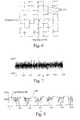
- the time domain data to be transmittedis shown in FIG. 7 , depicting approximately ten frames of data.
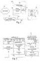
- the receiver 420is shown in FIG. 4 .
- the receiver 420must first obtain frame synchronization. It performs this task by processing the received samples from A/D converter 422 in a correlator 424 .
- the Frame Synchronizer 426re-arranges the samples such that the leading-edge samples in each frame are replaced by samples from the periodic extension. Alternatively, a cyclic prefix may be used, where the end of the data sequence is copied and pre-pended to the transmit sequence.
- An FFT transformer 428performs a transform of the real valued time domain signal and generates a complex frequency domain signal.
- the first framecontains known data and is used to determine the equalizer coefficients in the equalizer 430 .
- Equalizer 430processes subsequent blocks of received data using these coefficients and updates the coefficients based on an error signal.
- the frame synchronizer 426 and the correlator 424accomplish symbol timing.
- the receive time-domain samplesare passed to the correlator 424 .
- the correlator 424performs a sliding correlation of the samples spaced the length of the time-domain FFT period, which, in the preferred case, is one hundred twenty eight samples.
- the correlator 424then provides a correlation output 800 as shown in FIG. 8 .
- the length of the periodic extensionwas intentionally generated as a very long time (80 samples) so it is easy to visualize the correlation function in FIG. 8 . In practice the extension depends upon the physical medium as described herein, but typically is shorter than 80 samples. Alternatively, a method using pilot tones may be used.
- phase offsetresults in a progressive phase offset from bin to bin of a DFT, an examination of the extent of the phase offset between two known symbols will yield the sampling offset, and thus the frame index.
- the frame synchronizer 426examines the correlator output 800 and searches it for a high correlation output that is at least half the length of the periodic extension. The process is adaptive, starting with some threshold 802 , then adjusting down until it finds the correlation. Analysis of the correlation output may be facilitated by the application of a filter such as a moving average filter, or other low-pass filter.
- the synchronizer 426provides the index into the data buffer containing the first sample of the first frame of receive time-domain data, and also provides the threshold at which the correlation was found for the purposes of algorithm validation.
- FFT transformer 428operates on the synchronized time-domain data to generate the frequency domain spectrum.
- the Fourier transform used within block 428takes the real time-domain receive samples that have been properly framed and produces an output consisting of complex values containing real and imaginary components.
- the transformed frequency domain datarepresents the magnitude and phase of the carriers.
- the FFT pointsare commonly referred to as “frequency bins.”
- the length of the outputwill contain half as many points as the real valued time-domain receive signal because only the first 64 points are calculated.
- the other frequency domain pointsare merely complex conjugates of the desired points, and are therefore not needed.
- the equalizer 430is a frequency domain complex equalizer that simultaneously solves the problems of symbol timing error, clock error and drift, channel phase and attenuation distortion, and removes any number of echoes caused by reflections of unterminated wiring segments. This is accomplished in one mathematical step of low complexity.
- a block diagram of the equalizer 430is shown in FIG. 9 .
- the transmitted datais arranged in packets, with each packet consisting of concatenated frames transmitted in serial fashion.
- the first frame of a packetis an equalization frame of known symbols that is used to provide a coarse estimate of the channel.
- the receiver's equalizer 430is trained to the channel using this frame by forming the ratio of the expected symbol to the received symbol for each frequency bin within the frame.
- the ratios for each tap of equalizer filter 920are formed using the complex-valued frequency domain values that are readily available from the FFT block 428 .
- the resultis a sequence of points (e.g., a vector) where each point corresponds to a frequency bin, and each value is an estimate of the inverse of the channel response at that frequency.
- Multiplication of the frequency domain representation of the incoming frames by the equalizer tapsresults in a circular de-convolution of the channel impulse response.
- the circular de-convolutionis made possible by the periodic extension, which makes the receive data to appear as if it had been circularly convolved by the channel impulse response.
- the single step of multiplying the transformed data frames by the equalizer coefficients prior to demodulationcorrects for channel impulse response distortion, sampling offset, clock/timing error, etc.
- transceiver 400the use of only a single frame for the initial training of the equalizer 430 results in a lower signal to noise ratio than if the equalizer 430 is trained over a longer sequence of symbols. While this reduces the number of available constellation points (given a desired bit error rate), and hence reduces the data rate, the overall reduction of complexity in transceiver 400 is highly advantageous. For example, because the equalizer 430 is trained very quickly on a single frame of known symbols, the equalizer 430 need not retain channel information corresponding to a particular transmitter 402 of device 70 on LAN 20 . This is desirable, especially when numerous devices 70 are transmitting on the DMT LAN 20 .
- the equalizer 430would typically either have to store large amounts of equalization data for each of the other transmitting devices 70 on the DMT LAN and retrain every device when the LAN characteristics change, or it would have to perform a lengthy retraining procedure each time a DMT LAN transmitter 402 initiated a session. To retrain the equalizers for every device would require much additional protocol functionality to implement the retraining procedure. Such a scheme would also create undesirable transmission delays on LAN 20 .
- An alternative frequency domain equalization schemeis also provided.
- known equalization symbolsare inserted into the data stream such that every N th bin contains a known symbol.
- the known symbolsare referred to herein as equalization symbols, and the bins are referred to as equalization bins.
- every eighth binis an equalization bin, and is used in every data frame.
- the frequency response of the channel at frequencies corresponding to the remaining binsis then estimated by interpolating between the received equalization symbols in the equalization bins.
- the equalization symbolsmay vary from equalization bin to equalization bin, but preferably the same set of predetermined estimation symbols is sent in every data frame.
- a running average for each equalization binis calculated upon the receipt of a new frame once frame has been transformed to the frequency domain.
- the equalizer tapsare updated using the averaged points corresponding to the equalization bins in addition to the points interpolated there-between. Standard interpolation techniques may be used to obtain the entire channel estimate from the running average of the equalization bins.
- a decision feedback loopis used after the QAM demodulator to generate an error vector in DFE block 930 that is used to update the equalizer taps after each frame is processed.
- the DFE block 930allows the equalizer to track slow changes in the channel and to track clock error between the transmitter and receiver.
- the DFE structureis not used, however, in the second preferred equalizer that utilizes the interpolative techniques discussed above.
- the demodulator block 432takes the complex frequency domain points for each bin after equalization, then demodulates those points back to real data.
- Demodulator 432includes data slicers to determine the nearest constellation point to the received (and equalized) point.
- the demodulatormay include a trellis decoder and other FEC decoders.
- the descrambler 434reverses the scrambling of the data as described in the transmitter section based on the V.34 scrambler, or a block-based lookup table.
- DFE block 830may update the taps based upon the decoded data decisions instead of the slicer outputs because the data decisions may be more accurate due to FEC processing.
Landscapes
- Engineering & Computer Science (AREA)
- Computer Networks & Wireless Communication (AREA)
- Signal Processing (AREA)
- Power Engineering (AREA)
- Data Exchanges In Wide-Area Networks (AREA)
Abstract
Description
| SIMPLIFIED FORWARDER | MULTI-POINT FORWARDER |
| One PPP session per connection, | One PPP session for entire DMT |
| managed in PC | LAN network managed in the |
| Requires one IP session per | gateway |
| session, per FRD device | Multiple local IP addresses supported |
| Only one PPP session at a given | by single gateway PPP session |
| time | Multiple simultaneous IP sessions |
| Any computer on the DMT LAN | possible |
| can start a PPP session, but only | Any number of computers can start |
| one at a time | an IP session at any time |
| Full local DMT LAN support (file | Full local DMT LAN support (file |
| and printer sharing) | and printer sharing) |
| Minimal protocol processing in | Gateway becomes a router with NAT |
| the RU | |
for 0≦j>128, where the djare the time domain data points, n is the length of the IFFT, wkare the complex-valued symbols, and i=√{square root over (−1)}. The wkare set to a zero value for bins corresponding to frequencies that are not used. This is the case for at least the first, or DC, bin so as to pre vent interference with the operation of POTS devices connected to the
where D is the worst case maximum group delay in seconds, and Fsis the sampling rate (in seconds) of the A/D (and D/A) converter. For illustrative purposes, with an Fsof 1 MHz, and 40 μsec as the expected channel impulse response time as a result of group delay, an 80 sample extension is required. The calculation for the length of the periodic extension is a one-time calculation. The periodic extension simply appends the required number of samples to the time domain data.
for 0≦j <64, where the dkare the time domain data points, n is the length of the FFT, wjare the complex-valued symbols, and i=√{square root over (−1)}.
Claims (20)
Priority Applications (1)
| Application Number | Priority Date | Filing Date | Title |
|---|---|---|---|
| US09/885,220US6891887B1 (en) | 1998-05-27 | 2001-06-20 | Multi-carrier LAN adapter device using interpolative equalizer |
Applications Claiming Priority (2)
| Application Number | Priority Date | Filing Date | Title |
|---|---|---|---|
| US8596098A | 1998-05-27 | 1998-05-27 | |
| US09/885,220US6891887B1 (en) | 1998-05-27 | 2001-06-20 | Multi-carrier LAN adapter device using interpolative equalizer |
Related Parent Applications (1)
| Application Number | Title | Priority Date | Filing Date |
|---|---|---|---|
| US8596098AContinuation | 1998-05-27 | 1998-05-27 |
Publications (1)
| Publication Number | Publication Date |
|---|---|
| US6891887B1true US6891887B1 (en) | 2005-05-10 |
Family
ID=34548817
Family Applications (1)
| Application Number | Title | Priority Date | Filing Date |
|---|---|---|---|
| US09/885,220Expired - Fee RelatedUS6891887B1 (en) | 1998-05-27 | 2001-06-20 | Multi-carrier LAN adapter device using interpolative equalizer |
Country Status (1)
| Country | Link |
|---|---|
| US (1) | US6891887B1 (en) |
Cited By (18)
| Publication number | Priority date | Publication date | Assignee | Title |
|---|---|---|---|---|
| US20020059650A1 (en)* | 2000-08-03 | 2002-05-16 | Edwin Lyda | Distance learning system |
| US20020103005A1 (en)* | 2001-01-26 | 2002-08-01 | Watts La Vaughn F. | Combination personal data assistant and personal computing system dynamic memory reclamation |
| US20030063680A1 (en)* | 2001-09-28 | 2003-04-03 | Nec Usa, Inc. | Per-bin DFE for advanced OQAM-based multi-carrier wireless data transmission systems |
| US20030088706A1 (en)* | 2001-08-30 | 2003-05-08 | Chan Christina K. | System and method for simultaneously transporting different types of information over a power line |
| US20030206543A1 (en)* | 2002-05-03 | 2003-11-06 | Fischer Michael Andrew | Partitioned medium access control |
| US20030227643A1 (en)* | 2002-03-06 | 2003-12-11 | Pharos Systems International, Inc. | Document processing system including multi-device compatible interface and related methods |
| US20040057527A1 (en)* | 2000-12-13 | 2004-03-25 | Andre Frank | System and method for the data transmission of digital transmission data |
| US20050027881A1 (en)* | 2003-07-30 | 2005-02-03 | Nortel Networks Limited | Method and apparatus for direct frame switching using frame contained destination information |
| US20050099956A1 (en)* | 2003-07-11 | 2005-05-12 | Nec Corporation | Load distribution type network fault monitoring system and method of broadband router |
| US20050204062A1 (en)* | 2004-02-26 | 2005-09-15 | Nec Corporation | Subscriber line accommodation device and packet filtering method |
| US20060160553A1 (en)* | 2005-01-03 | 2006-07-20 | Nokia Corporation | Uplink communication in GSM/EDGE system |
| US20070162590A1 (en)* | 2000-04-04 | 2007-07-12 | Campbell Douglas A | Apparatus, systems, and method for communicating to a network through a virtual domain |
| EP1819098A4 (en)* | 2005-11-28 | 2008-04-16 | Huawei Tech Co Ltd | Method and device for testing transmission loss of communication line |
| US20100002717A1 (en)* | 2002-05-03 | 2010-01-07 | Conexant, Inc. | Partitioned Medium Access Control Implementation |
| WO2016179611A1 (en)* | 2015-05-07 | 2016-11-10 | Wood Michael C | Transparent traffic control device and method for securing internet-connected devices |
| US9882877B2 (en) | 2014-05-12 | 2018-01-30 | Michael C. Wood | Transparent traffic control device and method for securing internet-connected devices |
| CN107948045A (en)* | 2017-12-25 | 2018-04-20 | 上海京颐科技股份有限公司 | Doctors and patients' system based on bridge |
| US20220247493A1 (en)* | 2003-06-10 | 2022-08-04 | Alexander Ivan Soto | Communication system and method for an optical local area network |
Citations (94)
| Publication number | Priority date | Publication date | Assignee | Title |
|---|---|---|---|---|
| US3679882A (en) | 1970-06-11 | 1972-07-25 | Ibm | Fourier digital filter or equalizer and method of operation therefor |
| US4106103A (en) | 1976-07-19 | 1978-08-08 | Xerox Corporation | Derivation of discrete Fourier transform components of a time dependent signal |
| US4152649A (en) | 1976-07-08 | 1979-05-01 | International Business Machines Corporation | Channel equalization apparatus and method using the Fourier transform technique |
| US4227152A (en) | 1978-06-13 | 1980-10-07 | International Business Machines Corporation | Method and device for training an adaptive equalizer by means of an unknown data signal in a quadrature amplitude modulation transmission system |
| US4233589A (en) | 1979-05-25 | 1980-11-11 | Xerox Corporation | Active T-coupler for fiber optic local networks which permits collision detection |
| US4247908A (en) | 1978-12-08 | 1981-01-27 | Motorola, Inc. | Re-linked portable data terminal controller system |
| US4345250A (en) | 1980-12-22 | 1982-08-17 | Honeywell Information Systems Inc. | Information communication system with collision avoidance |
| US4430743A (en) | 1980-11-17 | 1984-02-07 | Nippon Electric Co., Ltd. | Fast start-up system for transversal equalizers |
| US4509206A (en) | 1982-05-04 | 1985-04-02 | Thomson-Csf | Receiver for multicarrier signals protected from unwanted signals |
| US4519074A (en) | 1983-05-31 | 1985-05-21 | Rca Corporation | Transceiver having collision detection capability for contention-formatted FDM local area networks |
| US4539689A (en) | 1978-04-26 | 1985-09-03 | Racal Data Communications, Inc. | Fast learn digital adaptive equalizer |
| US4652874A (en) | 1984-12-24 | 1987-03-24 | Motorola, Inc. | Serial communication interface for a local network controller |
| US4687788A (en) | 1982-10-08 | 1987-08-18 | The Dow Chemical Company | Dimensionally stable urethane elastomers |
| US4745600A (en) | 1985-07-09 | 1988-05-17 | Codex Corporation | Network collision detection and avoidance apparatus |
| US4751701A (en) | 1985-11-14 | 1988-06-14 | Hughes Network Systems, Inc. | TDM collision detector |
| US4760375A (en) | 1983-10-28 | 1988-07-26 | Josef Stecker | Data transmission cable |
| US4881222A (en) | 1987-03-12 | 1989-11-14 | Ant Nachrichtentechnik Gmbh | Multicarrier demodulator |
| US4885743A (en) | 1988-02-18 | 1989-12-05 | Codenoll Technology Corporation | Method and apparatus for detecting the collision of data packets |
| US4885742A (en) | 1988-01-28 | 1989-12-05 | Ricoh Company, Ltd. | Node apparatus and communication network |
| US4899217A (en) | 1987-12-01 | 1990-02-06 | Smart House Limited Partnership | Communication and energy control system for houses |
| US4901342A (en) | 1986-08-22 | 1990-02-13 | Jones Reese M | Local area network connecting computer products via long telephone lines |
| US4943980A (en) | 1989-05-02 | 1990-07-24 | Intelligent Modem Corporation | Multi-carrier high speed modem |
| US4959713A (en) | 1989-10-10 | 1990-09-25 | Matsushita Electric Industrial Co., Ltd. | Home automation system |
| US4965792A (en) | 1986-01-09 | 1990-10-23 | Ricoh Company, Ltd. | Collision/detection single node controlled local area network |
| US5003579A (en) | 1986-08-22 | 1991-03-26 | Farallon Computing, Incorporated | System for connecting computers via telephone lines |
| US5051720A (en) | 1989-11-13 | 1991-09-24 | Secure Telecom, Inc. | Remote control system using power line of remote site |
| US5117418A (en) | 1990-11-09 | 1992-05-26 | Intelligent Modem Corporation | Frequency domain adaptive echo canceller for full-duplex data transmission |
| US5121414A (en) | 1990-08-09 | 1992-06-09 | Motorola, Inc. | Carrier frequency offset equalization |
| US5128964A (en) | 1990-10-10 | 1992-07-07 | Intelligent Modem Corporation | Modulation method and apparatus for multicarrier data transmission |
| US5130793A (en) | 1988-07-22 | 1992-07-14 | Etat Francais | Reconfigurable multiple-point wired in-house network for simultaneous and/or alternative distribution of several types of signals, notably baseband images, and method for the configuration of a system such as this |
| US5166924A (en) | 1990-03-06 | 1992-11-24 | Mercury Digital Communications, Inc. | Echo cancellation in multi-frequency differentially encoded digital communications |
| US5195106A (en) | 1990-11-14 | 1993-03-16 | Motorola, Inc. | Method for channel adaptive detecting/equalize |
| US5197066A (en) | 1991-03-28 | 1993-03-23 | Sutterlin Philip H | Collision detection circuit for communications network |
| US5206886A (en) | 1990-04-16 | 1993-04-27 | Telebit Corporation | Method and apparatus for correcting for clock and carrier frequency offset, and phase jitter in mulicarrier modems |
| US5210530A (en) | 1991-01-04 | 1993-05-11 | Codex Corporation | Network management interface with internal dsd |
| US5226081A (en) | 1990-05-17 | 1993-07-06 | Fujitsu Limited | Multi-carrier communication system using ciphered carrier bit assignment information |
| US5228062A (en) | 1990-04-16 | 1993-07-13 | Telebit Corporation | Method and apparatus for correcting for clock and carrier frequency offset, and phase jitter in multicarrier modems |
| US5278844A (en) | 1991-04-11 | 1994-01-11 | Usa Digital Radio | Method and apparatus for digital audio broadcasting and reception |
| US5285474A (en) | 1992-06-12 | 1994-02-08 | The Board Of Trustees Of The Leland Stanford, Junior University | Method for equalizing a multicarrier signal in a multicarrier communication system |
| US5313169A (en) | 1990-11-30 | 1994-05-17 | Thomson-Csf | Method of realigning the local oscillators of a receiver and device for implementing the method |
| US5317596A (en) | 1992-12-01 | 1994-05-31 | The Board Of Trustees Of The Leland Stanford, Junior University | Method and apparatus for echo cancellation with discrete multitone modulation |
| US5319674A (en) | 1990-10-30 | 1994-06-07 | International Business Machines Corporation | Method for self-training adaptive equalization |
| US5329552A (en) | 1991-02-12 | 1994-07-12 | Thomson-Csf | Method of binary encoding the points of a constellation used in a multicarrier modulation of OFDM type |
| US5353287A (en) | 1992-03-25 | 1994-10-04 | Alcatel Network Systems, Inc. | Local area network with message priority |
| US5355375A (en) | 1993-03-18 | 1994-10-11 | Network Systems Corporation | Hub controller for providing deterministic access to CSMA local area network |
| US5377327A (en) | 1988-04-22 | 1994-12-27 | Digital Equipment Corporation | Congestion avoidance scheme for computer networks |
| US5400322A (en) | 1993-08-20 | 1995-03-21 | Amati Communications Corp. | Updating of bit allocations in a multicarrier modulation transmission system |
| US5410292A (en) | 1991-06-24 | 1995-04-25 | Sgs-Thomson Microelectronics S.A. | Method and system for communicating information within a dwelling or a property |
| US5461640A (en) | 1994-06-03 | 1995-10-24 | Texas Instruments Incorporated | Method and system for optimizing an equalizer in a data transmission system |
| US5479447A (en) | 1993-05-03 | 1995-12-26 | The Board Of Trustees Of The Leland Stanford, Junior University | Method and apparatus for adaptive, variable bandwidth, high-speed data transmission of a multicarrier signal over digital subscriber lines |
| US5519731A (en) | 1994-04-14 | 1996-05-21 | Amati Communications Corporation | ADSL compatible discrete multi-tone apparatus for mitigation of T1 noise |
| US5519727A (en) | 1992-12-25 | 1996-05-21 | Nec Corporation | Adaptive equalizer |
| US5521908A (en) | 1995-04-20 | 1996-05-28 | Tellabs Operations Inc. | Method and apparatus for providing reduced complexity echo cancellation in a multicarrier communication system |
| US5521937A (en) | 1993-10-08 | 1996-05-28 | Interdigital Technology Corporation | Multicarrier direct sequence spread system and method |
| US5539777A (en) | 1995-01-26 | 1996-07-23 | Motorola, Inc. | Method and apparatus for a DMT receiver having a data de-formatter coupled directly to a constellation decoder |
| WO1996024207A1 (en) | 1995-01-30 | 1996-08-08 | Motorola Inc. | Method and system for clearing a frequency band |
| US5553008A (en) | 1993-03-29 | 1996-09-03 | Epic Design Technology Inc. | Transistor-level timing and simulator and power analyzer |
| US5568476A (en) | 1994-10-26 | 1996-10-22 | 3Com Corporation | Method and apparatus for avoiding packet loss on a CSMA/CD-type local area network using receive-sense-based jam signal |
| US5570350A (en) | 1994-09-30 | 1996-10-29 | Lucent Technologies Inc. | CDMA cellular communications with multicarrier signal processing |
| US5572546A (en) | 1994-12-22 | 1996-11-05 | Motorola, Inc. | Data communications system with multilink protocol |
| US5572511A (en) | 1995-01-27 | 1996-11-05 | Tamarack Microelectronics, Inc. | Auto-adjustment circuit for collision detection of ethernet |
| US5592482A (en) | 1989-04-28 | 1997-01-07 | Abraham; Charles | Video distribution system using in-wall wiring |
| US5596577A (en) | 1995-05-02 | 1997-01-21 | Motorola, Inc. | Method and system for providing access by secondary stations to a shared transmission medium |
| US5596604A (en) | 1993-08-17 | 1997-01-21 | Amati Communications Corporation | Multicarrier modulation transmission system with variable delay |
| US5598401A (en) | 1995-03-21 | 1997-01-28 | Motorola, Inc. | Apparatus and method for a digital data communications device to operate in an analog mode |
| US5606577A (en) | 1995-01-26 | 1997-02-25 | Motorola Inc. | Method and apparatus for a DMT transmitter having a data for matter coupled directly to a constellation encoder |
| US5608725A (en) | 1995-01-26 | 1997-03-04 | Motorola, Inc. | Method and apparatus of a communications system having a DMT infrastructure |
| US5621662A (en) | 1994-02-15 | 1997-04-15 | Intellinet, Inc. | Home automation system |
| US5625871A (en) | 1994-09-30 | 1997-04-29 | Lucent Technologies Inc. | Cellular communications system with multicarrier signal processing |
| US5625651A (en) | 1994-06-02 | 1997-04-29 | Amati Communications, Inc. | Discrete multi-tone data transmission system using an overhead bus for synchronizing multiple remote units |
| US5627863A (en) | 1994-07-15 | 1997-05-06 | Amati Communications Corporation | Frame synchronization in multicarrier transmission systems |
| US5627828A (en) | 1994-03-15 | 1997-05-06 | Lg Semicon Co., Ltd. | Method and circuit for detecting data collisions in communication network |
| US5636246A (en) | 1994-11-16 | 1997-06-03 | Aware, Inc. | Multicarrier transmission system |
| US5636211A (en) | 1995-08-15 | 1997-06-03 | Motorola, Inc. | Universal multimedia access device |
| US5651009A (en) | 1995-05-02 | 1997-07-22 | Motorola, Inc. | System and method for hybrid contention/polling protocol collision resolution using a depth first search technique |
| US5655140A (en) | 1994-07-22 | 1997-08-05 | Network Peripherals | Apparatus for translating frames of data transferred between heterogeneous local area networks |
| US5659891A (en) | 1995-06-07 | 1997-08-19 | Mobile Telecommunication Technologies | Multicarrier techniques in bandlimited channels |
| US5668802A (en) | 1993-11-11 | 1997-09-16 | Gpt Limited | High-speed digital subscriber lines |
| EP0795984A2 (en) | 1996-03-15 | 1997-09-17 | Motorola, Inc. | Flexible asymmetrical digital subscriber line (ADSL) receiver, central office using same, and method therefor |
| EP0795977A2 (en) | 1996-03-15 | 1997-09-17 | Motorola, Inc. | Method of transmitting an ADSL signal simultaneously with an ISDN signal |
| US5671251A (en) | 1995-02-28 | 1997-09-23 | Motorola, Inc. | Apparatus and method for a data communications device to selectively operate as an analog modem, as a digital modem, and as a terminal adapter |
| US5694396A (en) | 1994-09-30 | 1997-12-02 | Lucent Technologies Inc. | Method and apparatus for processing multicarrier signals |
| US5729570A (en) | 1994-12-08 | 1998-03-17 | Stanford Telecommunications, Inc. | Orthogonal code division multiple access communication system having multicarrier modulation |
| US5809069A (en)* | 1996-07-19 | 1998-09-15 | Texas Instruments Incorporated | Frequency-domain carrierless AM-PM demodulator |
| US5838744A (en)* | 1996-10-22 | 1998-11-17 | Talx Corporation | High speed modem and method having jitter-free timing recovery |
| US5909463A (en) | 1996-11-04 | 1999-06-01 | Motorola, Inc. | Single-chip software configurable transceiver for asymmetric communication system |
| US6005893A (en) | 1997-09-23 | 1999-12-21 | Telefonaktiebolaget Lm Ericsson | Reduced complexity bit allocation to subchannels in a multi-carrier, high speed data transmission system |
| US6031868A (en)* | 1997-10-17 | 2000-02-29 | Analog Devices, Inc. | Asymmetric digital subscriber loop transceivers |
| US6038251A (en)* | 1996-05-09 | 2000-03-14 | Texas Instruments Incorporated | Direct equalization method |
| US6069899A (en) | 1997-08-28 | 2000-05-30 | Broadcam Homenetworking, Inc. | Home area network system and method |
| US6101216A (en) | 1997-10-03 | 2000-08-08 | Rockwell International Corporation | Splitterless digital subscriber line communication system |
| US6101182A (en) | 1996-04-18 | 2000-08-08 | Bell Atlantic Network Services, Inc. | Universal access multimedia data network |
| US6130893A (en) | 1997-10-09 | 2000-10-10 | Nortel Networks Corporation | Method and apparatus for multiplexing telephone lines over a common access network |
| US6154465A (en) | 1998-10-06 | 2000-11-28 | Vertical Networks, Inc. | Systems and methods for multiple mode voice and data communications using intelligenty bridged TDM and packet buses and methods for performing telephony and data functions using the same |
- 2001
- 2001-06-20USUS09/885,220patent/US6891887B1/ennot_activeExpired - Fee Related
Patent Citations (96)
| Publication number | Priority date | Publication date | Assignee | Title |
|---|---|---|---|---|
| US3679882A (en) | 1970-06-11 | 1972-07-25 | Ibm | Fourier digital filter or equalizer and method of operation therefor |
| US4152649A (en) | 1976-07-08 | 1979-05-01 | International Business Machines Corporation | Channel equalization apparatus and method using the Fourier transform technique |
| US4106103A (en) | 1976-07-19 | 1978-08-08 | Xerox Corporation | Derivation of discrete Fourier transform components of a time dependent signal |
| US4539689A (en) | 1978-04-26 | 1985-09-03 | Racal Data Communications, Inc. | Fast learn digital adaptive equalizer |
| US4227152A (en) | 1978-06-13 | 1980-10-07 | International Business Machines Corporation | Method and device for training an adaptive equalizer by means of an unknown data signal in a quadrature amplitude modulation transmission system |
| US4247908A (en) | 1978-12-08 | 1981-01-27 | Motorola, Inc. | Re-linked portable data terminal controller system |
| US4233589A (en) | 1979-05-25 | 1980-11-11 | Xerox Corporation | Active T-coupler for fiber optic local networks which permits collision detection |
| US4430743A (en) | 1980-11-17 | 1984-02-07 | Nippon Electric Co., Ltd. | Fast start-up system for transversal equalizers |
| US4345250A (en) | 1980-12-22 | 1982-08-17 | Honeywell Information Systems Inc. | Information communication system with collision avoidance |
| US4509206A (en) | 1982-05-04 | 1985-04-02 | Thomson-Csf | Receiver for multicarrier signals protected from unwanted signals |
| US4687788A (en) | 1982-10-08 | 1987-08-18 | The Dow Chemical Company | Dimensionally stable urethane elastomers |
| US4519074A (en) | 1983-05-31 | 1985-05-21 | Rca Corporation | Transceiver having collision detection capability for contention-formatted FDM local area networks |
| US4760375A (en) | 1983-10-28 | 1988-07-26 | Josef Stecker | Data transmission cable |
| US4652874A (en) | 1984-12-24 | 1987-03-24 | Motorola, Inc. | Serial communication interface for a local network controller |
| US4745600A (en) | 1985-07-09 | 1988-05-17 | Codex Corporation | Network collision detection and avoidance apparatus |
| US4751701A (en) | 1985-11-14 | 1988-06-14 | Hughes Network Systems, Inc. | TDM collision detector |
| US4965792A (en) | 1986-01-09 | 1990-10-23 | Ricoh Company, Ltd. | Collision/detection single node controlled local area network |
| US5003579A (en) | 1986-08-22 | 1991-03-26 | Farallon Computing, Incorporated | System for connecting computers via telephone lines |
| US4901342A (en) | 1986-08-22 | 1990-02-13 | Jones Reese M | Local area network connecting computer products via long telephone lines |
| US4881222A (en) | 1987-03-12 | 1989-11-14 | Ant Nachrichtentechnik Gmbh | Multicarrier demodulator |
| US4899217A (en) | 1987-12-01 | 1990-02-06 | Smart House Limited Partnership | Communication and energy control system for houses |
| US4885742A (en) | 1988-01-28 | 1989-12-05 | Ricoh Company, Ltd. | Node apparatus and communication network |
| US4885743A (en) | 1988-02-18 | 1989-12-05 | Codenoll Technology Corporation | Method and apparatus for detecting the collision of data packets |
| US5377327A (en) | 1988-04-22 | 1994-12-27 | Digital Equipment Corporation | Congestion avoidance scheme for computer networks |
| US5130793A (en) | 1988-07-22 | 1992-07-14 | Etat Francais | Reconfigurable multiple-point wired in-house network for simultaneous and/or alternative distribution of several types of signals, notably baseband images, and method for the configuration of a system such as this |
| US5592482A (en) | 1989-04-28 | 1997-01-07 | Abraham; Charles | Video distribution system using in-wall wiring |
| US4943980A (en) | 1989-05-02 | 1990-07-24 | Intelligent Modem Corporation | Multi-carrier high speed modem |
| US4959713A (en) | 1989-10-10 | 1990-09-25 | Matsushita Electric Industrial Co., Ltd. | Home automation system |
| US5051720A (en) | 1989-11-13 | 1991-09-24 | Secure Telecom, Inc. | Remote control system using power line of remote site |
| US5166924A (en) | 1990-03-06 | 1992-11-24 | Mercury Digital Communications, Inc. | Echo cancellation in multi-frequency differentially encoded digital communications |
| US5206886A (en) | 1990-04-16 | 1993-04-27 | Telebit Corporation | Method and apparatus for correcting for clock and carrier frequency offset, and phase jitter in mulicarrier modems |
| US5228062A (en) | 1990-04-16 | 1993-07-13 | Telebit Corporation | Method and apparatus for correcting for clock and carrier frequency offset, and phase jitter in multicarrier modems |
| US5226081A (en) | 1990-05-17 | 1993-07-06 | Fujitsu Limited | Multi-carrier communication system using ciphered carrier bit assignment information |
| US5121414A (en) | 1990-08-09 | 1992-06-09 | Motorola, Inc. | Carrier frequency offset equalization |
| US5128964A (en) | 1990-10-10 | 1992-07-07 | Intelligent Modem Corporation | Modulation method and apparatus for multicarrier data transmission |
| US5319674A (en) | 1990-10-30 | 1994-06-07 | International Business Machines Corporation | Method for self-training adaptive equalization |
| US5117418A (en) | 1990-11-09 | 1992-05-26 | Intelligent Modem Corporation | Frequency domain adaptive echo canceller for full-duplex data transmission |
| US5195106A (en) | 1990-11-14 | 1993-03-16 | Motorola, Inc. | Method for channel adaptive detecting/equalize |
| US5313169A (en) | 1990-11-30 | 1994-05-17 | Thomson-Csf | Method of realigning the local oscillators of a receiver and device for implementing the method |
| US5210530A (en) | 1991-01-04 | 1993-05-11 | Codex Corporation | Network management interface with internal dsd |
| US5329552A (en) | 1991-02-12 | 1994-07-12 | Thomson-Csf | Method of binary encoding the points of a constellation used in a multicarrier modulation of OFDM type |
| US5197066A (en) | 1991-03-28 | 1993-03-23 | Sutterlin Philip H | Collision detection circuit for communications network |
| US5278844A (en) | 1991-04-11 | 1994-01-11 | Usa Digital Radio | Method and apparatus for digital audio broadcasting and reception |
| US5410292A (en) | 1991-06-24 | 1995-04-25 | Sgs-Thomson Microelectronics S.A. | Method and system for communicating information within a dwelling or a property |
| US5353287A (en) | 1992-03-25 | 1994-10-04 | Alcatel Network Systems, Inc. | Local area network with message priority |
| US5285474A (en) | 1992-06-12 | 1994-02-08 | The Board Of Trustees Of The Leland Stanford, Junior University | Method for equalizing a multicarrier signal in a multicarrier communication system |
| US5317596A (en) | 1992-12-01 | 1994-05-31 | The Board Of Trustees Of The Leland Stanford, Junior University | Method and apparatus for echo cancellation with discrete multitone modulation |
| US5519727A (en) | 1992-12-25 | 1996-05-21 | Nec Corporation | Adaptive equalizer |
| US5355375A (en) | 1993-03-18 | 1994-10-11 | Network Systems Corporation | Hub controller for providing deterministic access to CSMA local area network |
| US5553008A (en) | 1993-03-29 | 1996-09-03 | Epic Design Technology Inc. | Transistor-level timing and simulator and power analyzer |
| US5479447A (en) | 1993-05-03 | 1995-12-26 | The Board Of Trustees Of The Leland Stanford, Junior University | Method and apparatus for adaptive, variable bandwidth, high-speed data transmission of a multicarrier signal over digital subscriber lines |
| US5596604A (en) | 1993-08-17 | 1997-01-21 | Amati Communications Corporation | Multicarrier modulation transmission system with variable delay |
| US5400322A (en) | 1993-08-20 | 1995-03-21 | Amati Communications Corp. | Updating of bit allocations in a multicarrier modulation transmission system |
| US5521937A (en) | 1993-10-08 | 1996-05-28 | Interdigital Technology Corporation | Multicarrier direct sequence spread system and method |
| US5668802A (en) | 1993-11-11 | 1997-09-16 | Gpt Limited | High-speed digital subscriber lines |
| US5621662A (en) | 1994-02-15 | 1997-04-15 | Intellinet, Inc. | Home automation system |
| US5627828A (en) | 1994-03-15 | 1997-05-06 | Lg Semicon Co., Ltd. | Method and circuit for detecting data collisions in communication network |
| US5519731A (en) | 1994-04-14 | 1996-05-21 | Amati Communications Corporation | ADSL compatible discrete multi-tone apparatus for mitigation of T1 noise |
| US5673290A (en) | 1994-04-14 | 1997-09-30 | Amati Communications Corporation | ADSL compatible discrete multi-tone apparatus |
| US5625651A (en) | 1994-06-02 | 1997-04-29 | Amati Communications, Inc. | Discrete multi-tone data transmission system using an overhead bus for synchronizing multiple remote units |
| US5461640A (en) | 1994-06-03 | 1995-10-24 | Texas Instruments Incorporated | Method and system for optimizing an equalizer in a data transmission system |
| US5627863A (en) | 1994-07-15 | 1997-05-06 | Amati Communications Corporation | Frame synchronization in multicarrier transmission systems |
| US5655140A (en) | 1994-07-22 | 1997-08-05 | Network Peripherals | Apparatus for translating frames of data transferred between heterogeneous local area networks |
| US5694395A (en) | 1994-09-30 | 1997-12-02 | Lucent Technologies, Inc. | Method and apparatus for processing multicarrier signals |
| US5625871A (en) | 1994-09-30 | 1997-04-29 | Lucent Technologies Inc. | Cellular communications system with multicarrier signal processing |
| US5570350A (en) | 1994-09-30 | 1996-10-29 | Lucent Technologies Inc. | CDMA cellular communications with multicarrier signal processing |
| US5694396A (en) | 1994-09-30 | 1997-12-02 | Lucent Technologies Inc. | Method and apparatus for processing multicarrier signals |
| US5568476A (en) | 1994-10-26 | 1996-10-22 | 3Com Corporation | Method and apparatus for avoiding packet loss on a CSMA/CD-type local area network using receive-sense-based jam signal |
| US5636246A (en) | 1994-11-16 | 1997-06-03 | Aware, Inc. | Multicarrier transmission system |
| US5729570A (en) | 1994-12-08 | 1998-03-17 | Stanford Telecommunications, Inc. | Orthogonal code division multiple access communication system having multicarrier modulation |
| US5572546A (en) | 1994-12-22 | 1996-11-05 | Motorola, Inc. | Data communications system with multilink protocol |
| US5608725A (en) | 1995-01-26 | 1997-03-04 | Motorola, Inc. | Method and apparatus of a communications system having a DMT infrastructure |
| US5606577A (en) | 1995-01-26 | 1997-02-25 | Motorola Inc. | Method and apparatus for a DMT transmitter having a data for matter coupled directly to a constellation encoder |
| US5539777A (en) | 1995-01-26 | 1996-07-23 | Motorola, Inc. | Method and apparatus for a DMT receiver having a data de-formatter coupled directly to a constellation decoder |
| US5572511A (en) | 1995-01-27 | 1996-11-05 | Tamarack Microelectronics, Inc. | Auto-adjustment circuit for collision detection of ethernet |
| WO1996024207A1 (en) | 1995-01-30 | 1996-08-08 | Motorola Inc. | Method and system for clearing a frequency band |
| US5671251A (en) | 1995-02-28 | 1997-09-23 | Motorola, Inc. | Apparatus and method for a data communications device to selectively operate as an analog modem, as a digital modem, and as a terminal adapter |
| US5598401A (en) | 1995-03-21 | 1997-01-28 | Motorola, Inc. | Apparatus and method for a digital data communications device to operate in an analog mode |
| US5521908A (en) | 1995-04-20 | 1996-05-28 | Tellabs Operations Inc. | Method and apparatus for providing reduced complexity echo cancellation in a multicarrier communication system |
| US5596577A (en) | 1995-05-02 | 1997-01-21 | Motorola, Inc. | Method and system for providing access by secondary stations to a shared transmission medium |
| US5651009A (en) | 1995-05-02 | 1997-07-22 | Motorola, Inc. | System and method for hybrid contention/polling protocol collision resolution using a depth first search technique |
| US5659891A (en) | 1995-06-07 | 1997-08-19 | Mobile Telecommunication Technologies | Multicarrier techniques in bandlimited channels |
| US5636211A (en) | 1995-08-15 | 1997-06-03 | Motorola, Inc. | Universal multimedia access device |
| EP0795984A2 (en) | 1996-03-15 | 1997-09-17 | Motorola, Inc. | Flexible asymmetrical digital subscriber line (ADSL) receiver, central office using same, and method therefor |
| EP0795977A2 (en) | 1996-03-15 | 1997-09-17 | Motorola, Inc. | Method of transmitting an ADSL signal simultaneously with an ISDN signal |
| US6101182A (en) | 1996-04-18 | 2000-08-08 | Bell Atlantic Network Services, Inc. | Universal access multimedia data network |
| US6038251A (en)* | 1996-05-09 | 2000-03-14 | Texas Instruments Incorporated | Direct equalization method |
| US5809069A (en)* | 1996-07-19 | 1998-09-15 | Texas Instruments Incorporated | Frequency-domain carrierless AM-PM demodulator |
| US5838744A (en)* | 1996-10-22 | 1998-11-17 | Talx Corporation | High speed modem and method having jitter-free timing recovery |
| US5909463A (en) | 1996-11-04 | 1999-06-01 | Motorola, Inc. | Single-chip software configurable transceiver for asymmetric communication system |
| US6069899A (en) | 1997-08-28 | 2000-05-30 | Broadcam Homenetworking, Inc. | Home area network system and method |
| US6005893A (en) | 1997-09-23 | 1999-12-21 | Telefonaktiebolaget Lm Ericsson | Reduced complexity bit allocation to subchannels in a multi-carrier, high speed data transmission system |
| US6101216A (en) | 1997-10-03 | 2000-08-08 | Rockwell International Corporation | Splitterless digital subscriber line communication system |
| US6130893A (en) | 1997-10-09 | 2000-10-10 | Nortel Networks Corporation | Method and apparatus for multiplexing telephone lines over a common access network |
| US6031868A (en)* | 1997-10-17 | 2000-02-29 | Analog Devices, Inc. | Asymmetric digital subscriber loop transceivers |
| US6154465A (en) | 1998-10-06 | 2000-11-28 | Vertical Networks, Inc. | Systems and methods for multiple mode voice and data communications using intelligenty bridged TDM and packet buses and methods for performing telephony and data functions using the same |
Non-Patent Citations (18)
| Title |
|---|
| Antipolis, Sophia, A Conceptual Study of OFDM-Based Multiple Access Schemes, Part 4: Tracking of Time and Frequency Offset, Telia Research, Dec. 1996, pp. 1-12. |
| Edfors, O., Sandell, M., Van De Beek, J., Landstrom, D., Sjoberg, F., An Introduction to Orthogonal Frequency-Division Multiplexing, Sep. 1996, pp. 1-58. |
| Edfors, O., Sandell, M., Van De Beek, J., Wilson, S., Borjesson, P., Analysis of DFT-Based Channel Estimators for OFDM, Vehicular Technology Conference (VTC'96), Chicago, Illinois, Jul. 25-28, 1995, pp. 1-25. |
| Edfors, O., Sandell, M., Van De Beek, J., Wilson, S., Borjesson, P., OFDM Channel Estimation by Singular Value Decomposition, Division of Signal Processing, Lulea University of Technology, Lulea, Sweden, Purdue University, School of Electrical and Computer Engineering, West Lafayette, Indiana, pp. 1-5. |
| Edfors, Ove, Low-Complexity Algorithms in Digital Receivers, Doctoral Thesis, Lulea University of Technology, Sep. 1996, pp. 1-90. |
| Isaksson, Mikael, Proposal: Option for In-Band POT and ISDN, Standards Project: T1E1.4:VDSL, Sep. 22-26, 1997, pp. 1-5. |
| Lulea University of Technology, Division of Signal Processing, Synchronization in OFDM, Mar. 27, 1998, pp. 1-3. |
| Nilsson, R., Edfors, O., Sandell, M., Borjesson, P., An Analysis of Two-Dimensional Pilot-Symbol Assisted Modulation for OFDM, Division of Signal Processing, Lulea University of Technology, Sweden, Department of Applied Electronics, Lund University, Lund, Sweden, Lucent Technologies, Bell Labs, Windmill Hill Business Park, Swindon, UK, pp. 1-4. |
| Sandell, M., Edfors, O., A Comparative Study of Pilot-Based Channel Estimators for Wireless OFDM, Sep. 1996, pp. 1-34. |
| Sandell, M., Van De Beek, J., Borjesson, P., Timing and Frequency Synchronization in OFDM Systems Using the Cyclic Prefix, Division of Signal Processing, Lulea University of Technology, Lulea, Sweden, pp. 1-4. |
| Sidhu, I., Grabelsky, D., A Simple and Efficient Medium Access Layer Protocol for Local Area Networks with Multiple-Priority Traffic, Advanced Technologies, Carrier Systems Division, 3Corn, pp. 1-3. |
| Van De Beek, J., Edfors, O., Borjesson, P., Wahlqvist, M., Ostberg, C., A Conceptual Study of OFDM-Based Multiple Access Schemes, Part 2: Channel Estimation in the Uplink, Lulea University of Technology, Lulea, Sweden, Telia Research, Lulea, Sweden, pp. 1-7. |
| Van De Beek, J., Edfors, O., Borjesson, P., Wahlqvist, M., Ostberg, C., A Conceptual Study of OFDM-Based Multiple Access Schemes, Part 3: Performance Evaluation of a Coded System, Lulea University of Technology, Lulea, Sweden, Telia Research, Lulea, Sweden, pp. 1-6. |
| Van De Beek, J., Edfors, O., Sandell, M., Wilson, S., Borjesson, P., On Channel Estimation in OFDM Systems, Division of Signal Processing, Lulea University of Technology, Sweden, Purdue University, School of Engineering, West Lafayette, Indiana, pp. 1-5. |
| Van De Beek, J., Sandell, M., Borjesson, P., ML Estimation of Timing and Frequency Offset in Multicarrier Systems, Division of Signal Processing, Lulea University of Technology, Lulea, Sweden, Apr., 1996, pp. 1-24. |
| Van De Beek, J., Sandell, M., Borjesson, P., On Synchronization in OFDM Systems Using the Cyclic Prefix, Division of Signal Processing, Lulea University of Technology, Lulea, Sweden, pp. 1-5. |
| Van De Beek, J., Sandell, M., Isaksson, M., Borjesson, P., Low-Complex Frame Synchronization in OFDM Systems, Division of Signal Processing, Lulea University of Technology, Lulea, Sweden, Telia Research, Lulea, Sweden, pp. 1-5. |
| Wahlqvist, M., Ostberg, C., Van De Beek, J., Edfors, O., Borjesson, P., A Conceptual Study of OFDM-Based Multiple Access Schemes, Part 1: Air Interface Requirements, Lulea University of Technology, Lulea, Sweden, Telia Research, Lulea, Sweden, pp. 1-7. |
Cited By (35)
| Publication number | Priority date | Publication date | Assignee | Title |
|---|---|---|---|---|
| US8370457B2 (en)* | 2000-04-04 | 2013-02-05 | Darmate Glassworks Llc | Network communication through a virtual domain |
| US20070162590A1 (en)* | 2000-04-04 | 2007-07-12 | Campbell Douglas A | Apparatus, systems, and method for communicating to a network through a virtual domain |
| US8762498B2 (en) | 2000-04-04 | 2014-06-24 | Darmate Glassworks Llc | Apparatus, system, and method for communicating to a network through a virtual domain |
| US7434243B2 (en)* | 2000-08-03 | 2008-10-07 | Edwin Lyda | Response apparatus method and system |
| US20020059650A1 (en)* | 2000-08-03 | 2002-05-16 | Edwin Lyda | Distance learning system |
| US7330512B2 (en)* | 2000-12-13 | 2008-02-12 | Siemens Aktiengesellschaft | System and method for the data transmission of digital transmission data |
| US20040057527A1 (en)* | 2000-12-13 | 2004-03-25 | Andre Frank | System and method for the data transmission of digital transmission data |
| US8331985B2 (en) | 2001-01-26 | 2012-12-11 | Dell Products L.P. | Combination personal data assistant and personal computing system dynamic memory reclamation |
| US8170610B2 (en)* | 2001-01-26 | 2012-05-01 | Dell Products L.P. | Combination personal data assistant and personal computing system dynamic memory reclamation |
| US20100191891A1 (en)* | 2001-01-26 | 2010-07-29 | Watts Jr La Vaughn F | Combination Personal Data Assistant and Personal Computing System Dynamic Memory Reclamation |
| US20020103005A1 (en)* | 2001-01-26 | 2002-08-01 | Watts La Vaughn F. | Combination personal data assistant and personal computing system dynamic memory reclamation |
| US20030088706A1 (en)* | 2001-08-30 | 2003-05-08 | Chan Christina K. | System and method for simultaneously transporting different types of information over a power line |
| US7447200B2 (en)* | 2001-08-30 | 2008-11-04 | Maxim Integrated Products, Inc. | System and method for simultaneously transporting different types of information over a power line |
| US20030063680A1 (en)* | 2001-09-28 | 2003-04-03 | Nec Usa, Inc. | Per-bin DFE for advanced OQAM-based multi-carrier wireless data transmission systems |
| US7436881B2 (en)* | 2001-09-28 | 2008-10-14 | Nec Corporation | Per-bin DFE for advanced OQAM-based multi-carrier wireless data transmission systems |
| US20030227643A1 (en)* | 2002-03-06 | 2003-12-11 | Pharos Systems International, Inc. | Document processing system including multi-device compatible interface and related methods |
| US7366799B2 (en)* | 2002-03-06 | 2008-04-29 | Pharos Systems International, Inc. | Document processing system including multi-device compatible interface and related methods |
| US8144733B2 (en) | 2002-05-03 | 2012-03-27 | Intellectual Ventures I Llc | Partitioned medium access control implementation |
| US20100002717A1 (en)* | 2002-05-03 | 2010-01-07 | Conexant, Inc. | Partitioned Medium Access Control Implementation |
| US20030206543A1 (en)* | 2002-05-03 | 2003-11-06 | Fischer Michael Andrew | Partitioned medium access control |
| US20220247493A1 (en)* | 2003-06-10 | 2022-08-04 | Alexander Ivan Soto | Communication system and method for an optical local area network |
| US20050099956A1 (en)* | 2003-07-11 | 2005-05-12 | Nec Corporation | Load distribution type network fault monitoring system and method of broadband router |
| US8228916B2 (en) | 2003-07-30 | 2012-07-24 | Rockstar Bidco L.P. | Method and apparatus for direct frame switching using frame contained destination information |
| US20100215045A1 (en)* | 2003-07-30 | 2010-08-26 | Figueira Norival R | Method and Apparatus for Direct Frame Switching Using Frame Contained Destination Information |
| US20050027881A1 (en)* | 2003-07-30 | 2005-02-03 | Nortel Networks Limited | Method and apparatus for direct frame switching using frame contained destination information |
| US7697527B2 (en)* | 2003-07-30 | 2010-04-13 | Nortel Networks Limited | Method and apparatus for direct frame switching using frame contained destination information |
| US9019963B2 (en) | 2003-07-30 | 2015-04-28 | Constellation Technologies, LLC | Method and apparatus for direct frame switching using frame contained destination information |
| US7860029B2 (en)* | 2004-02-26 | 2010-12-28 | Nec Corporation | Subscriber line accommodation device and packet filtering method |
| US20050204062A1 (en)* | 2004-02-26 | 2005-09-15 | Nec Corporation | Subscriber line accommodation device and packet filtering method |
| US20060160553A1 (en)* | 2005-01-03 | 2006-07-20 | Nokia Corporation | Uplink communication in GSM/EDGE system |
| US7672642B2 (en)* | 2005-01-03 | 2010-03-02 | Nokia Corporaation | Uplink communication in GSM/EDGE system |
| EP1819098A4 (en)* | 2005-11-28 | 2008-04-16 | Huawei Tech Co Ltd | Method and device for testing transmission loss of communication line |
| US9882877B2 (en) | 2014-05-12 | 2018-01-30 | Michael C. Wood | Transparent traffic control device and method for securing internet-connected devices |
| WO2016179611A1 (en)* | 2015-05-07 | 2016-11-10 | Wood Michael C | Transparent traffic control device and method for securing internet-connected devices |
| CN107948045A (en)* | 2017-12-25 | 2018-04-20 | 上海京颐科技股份有限公司 | Doctors and patients' system based on bridge |
Similar Documents
| Publication | Publication Date | Title |
|---|---|---|
| US6704317B1 (en) | Multi-carrier LAN modem server | |
| US7529229B1 (en) | Converged home gateway | |
| US6507585B1 (en) | Multi-carrier LAN adapter device using frequency domain equalizer | |
| US6891887B1 (en) | Multi-carrier LAN adapter device using interpolative equalizer | |
| CA2217073C (en) | Multimode digital modem | |
| US6137839A (en) | Variable scaling of 16-bit fixed point fast fourier forward and inverse transforms to improve precision for implementation of discrete multitone for asymmetric digital subscriber loops | |
| US5987061A (en) | Modem initialization process for line code and rate selection in DSL data communication | |
| US5970088A (en) | Reverse channel next cancellation for MDSL modem pool | |
| US6021167A (en) | Fast equalizer training and frame synchronization algorithms for discrete multi-tone (DMT) system | |
| US6219378B1 (en) | Digital subscriber line modem initialization | |
| US6377683B1 (en) | Low complexity frequency domain echo canceller for DMT transceivers | |
| US5999563A (en) | Rate negotiation for variable-rate digital subscriber line signaling | |
| US5910970A (en) | MDSL host interface requirement specification | |
| US6414952B2 (en) | Virtual gateway system and method | |
| US6044107A (en) | Method for interoperability of a T1E1.4 compliant ADSL modem and a simpler modem | |
| US6038251A (en) | Direct equalization method | |
| US6021158A (en) | Hybrid wireless wire-line network integration and management | |
| US6002722A (en) | Multimode digital modem | |
| US7075999B2 (en) | Multicarrier modulation with data dependent frequency-domain redundancy | |
| US6389062B1 (en) | Adaptive frequency domain equalizer circuits, systems, and methods for discrete multitone based digital subscriber line modem | |
| EP0831624A2 (en) | A modem | |
| EP1049301A2 (en) | Sampling clock correction in a multicarrier receiver | |
| EP0828363A2 (en) | Multicode modem with a plurality of analogue front ends | |
| US20050276340A1 (en) | Method and system for determining symbol boundary timing in a multicarrier data transmission system | |
| US20050276339A1 (en) | Training sequence for symbol boundary detection in a multicarrier data transmission system |
Legal Events
| Date | Code | Title | Description |
|---|---|---|---|
| AS | Assignment | Owner name:3COM CORPORATION, CALIFORNIA Free format text:ASSIGNMENT OF ASSIGNORS INTEREST;ASSIGNOR:DOBSON, WILLIAM KURT;REEL/FRAME:015844/0792 Effective date:19980526 | |
| FPAY | Fee payment | Year of fee payment:4 | |
| AS | Assignment | Owner name:HEWLETT-PACKARD COMPANY, CALIFORNIA Free format text:MERGER;ASSIGNOR:3COM CORPORATION;REEL/FRAME:024630/0820 Effective date:20100428 | |
| AS | Assignment | Owner name:HEWLETT-PACKARD COMPANY, CALIFORNIA Free format text:CORRECTIVE ASSIGNMENT TO CORRECT THE SEE ATTACHED;ASSIGNOR:3COM CORPORATION;REEL/FRAME:025039/0844 Effective date:20100428 | |
| AS | Assignment | Owner name:HEWLETT-PACKARD DEVELOPMENT COMPANY, L.P., TEXAS Free format text:ASSIGNMENT OF ASSIGNORS INTEREST;ASSIGNOR:HEWLETT-PACKARD COMPANY;REEL/FRAME:027329/0044 Effective date:20030131 | |
| AS | Assignment | Owner name:HEWLETT-PACKARD DEVELOPMENT COMPANY, L.P., TEXAS Free format text:CORRECTIVE ASSIGNMENT PREVIUOSLY RECORDED ON REEL 027329 FRAME 0001 AND 0044;ASSIGNOR:HEWLETT-PACKARD COMPANY;REEL/FRAME:028911/0846 Effective date:20111010 | |
| FPAY | Fee payment | Year of fee payment:8 | |
| AS | Assignment | Owner name:HEWLETT PACKARD ENTERPRISE DEVELOPMENT LP, TEXAS Free format text:ASSIGNMENT OF ASSIGNORS INTEREST;ASSIGNOR:HEWLETT-PACKARD DEVELOPMENT COMPANY, L.P.;REEL/FRAME:037079/0001 Effective date:20151027 | |
| REMI | Maintenance fee reminder mailed | ||
| LAPS | Lapse for failure to pay maintenance fees | ||
| STCH | Information on status: patent discontinuation | Free format text:PATENT EXPIRED DUE TO NONPAYMENT OF MAINTENANCE FEES UNDER 37 CFR 1.362 | |
| FP | Lapsed due to failure to pay maintenance fee | Effective date:20170510 |