US6891677B2 - Subwavelength optical microstructure light-redirecting films - Google Patents
Subwavelength optical microstructure light-redirecting filmsDownload PDFInfo
- Publication number
- US6891677B2 US6891677B2US10/445,375US44537503AUS6891677B2US 6891677 B2US6891677 B2US 6891677B2US 44537503 AUS44537503 AUS 44537503AUS 6891677 B2US6891677 B2US 6891677B2
- Authority
- US
- United States
- Prior art keywords
- light
- moth
- film
- linear
- eye
- Prior art date
- Legal status (The legal status is an assumption and is not a legal conclusion. Google has not performed a legal analysis and makes no representation as to the accuracy of the status listed.)
- Expired - Fee Related
Links
- 230000003287optical effectEffects0.000titleclaimsdescription40
- 238000005299abrasionMethods0.000claimsdescription7
- 230000009467reductionEffects0.000claimsdescription7
- 239000010408filmSubstances0.000description142
- 238000009826distributionMethods0.000description32
- 239000010410layerSubstances0.000description28
- 230000005540biological transmissionEffects0.000description11
- 239000000463materialSubstances0.000description11
- 239000000758substrateSubstances0.000description11
- 229920000728polyesterPolymers0.000description9
- 230000000694effectsEffects0.000description7
- 238000000034methodMethods0.000description7
- 230000006872improvementEffects0.000description6
- 238000005266castingMethods0.000description5
- 230000008901benefitEffects0.000description4
- 230000008859changeEffects0.000description4
- 230000002708enhancing effectEffects0.000description4
- 238000005286illuminationMethods0.000description4
- 230000001965increasing effectEffects0.000description4
- 238000000576coating methodMethods0.000description3
- 238000009304pastoral farmingMethods0.000description3
- 229920006267polyester filmPolymers0.000description3
- 230000008569processEffects0.000description3
- PXHVJJICTQNCMI-UHFFFAOYSA-NNickelChemical compound[Ni]PXHVJJICTQNCMI-UHFFFAOYSA-N0.000description2
- 239000006117anti-reflective coatingSubstances0.000description2
- 230000009286beneficial effectEffects0.000description2
- 239000013590bulk materialSubstances0.000description2
- 230000000052comparative effectEffects0.000description2
- 238000009792diffusion processMethods0.000description2
- 239000004973liquid crystal related substanceSubstances0.000description2
- 239000002245particleSubstances0.000description2
- 230000010287polarizationEffects0.000description2
- 239000004417polycarbonateSubstances0.000description2
- 229920000515polycarbonatePolymers0.000description2
- 229920000642polymerPolymers0.000description2
- 239000004800polyvinyl chlorideSubstances0.000description2
- 229920000915polyvinyl chloridePolymers0.000description2
- 238000004064recyclingMethods0.000description2
- 238000011160researchMethods0.000description2
- 230000004044responseEffects0.000description2
- 238000010022rotary screen printingMethods0.000description2
- 239000011343solid materialSubstances0.000description2
- 230000007480spreadingEffects0.000description2
- 238000003892spreadingMethods0.000description2
- 239000010409thin filmSubstances0.000description2
- 239000011800void materialSubstances0.000description2
- 239000004743PolypropyleneSubstances0.000description1
- NIXOWILDQLNWCW-UHFFFAOYSA-Nacrylic acid groupChemical groupC(C=C)(=O)ONIXOWILDQLNWCW-UHFFFAOYSA-N0.000description1
- XAGFODPZIPBFFR-UHFFFAOYSA-NaluminiumChemical compound[Al]XAGFODPZIPBFFR-UHFFFAOYSA-N0.000description1
- 229910052782aluminiumInorganic materials0.000description1
- 238000004458analytical methodMethods0.000description1
- 238000013459approachMethods0.000description1
- 238000003491arrayMethods0.000description1
- 230000015572biosynthetic processEffects0.000description1
- 239000003086colorantSubstances0.000description1
- 238000011109contaminationMethods0.000description1
- 230000007423decreaseEffects0.000description1
- 230000001419dependent effectEffects0.000description1
- 230000001066destructive effectEffects0.000description1
- 239000000428dustSubstances0.000description1
- 238000005323electroformingMethods0.000description1
- 239000011521glassSubstances0.000description1
- 238000000025interference lithographyMethods0.000description1
- 239000007788liquidSubstances0.000description1
- 239000011159matrix materialSubstances0.000description1
- 238000005259measurementMethods0.000description1
- 238000000465mouldingMethods0.000description1
- 229910052759nickelInorganic materials0.000description1
- 238000010943off-gassingMethods0.000description1
- 238000005457optimizationMethods0.000description1
- -1polypropylenePolymers0.000description1
- 229920001155polypropylenePolymers0.000description1
- 238000007788rougheningMethods0.000description1
- 238000001228spectrumMethods0.000description1
- 239000002344surface layerSubstances0.000description1
- 230000007704transitionEffects0.000description1
- 238000009827uniform distributionMethods0.000description1
Images


Classifications
- G—PHYSICS
- G02—OPTICS
- G02B—OPTICAL ELEMENTS, SYSTEMS OR APPARATUS
- G02B1/00—Optical elements characterised by the material of which they are made; Optical coatings for optical elements
- G02B1/10—Optical coatings produced by application to, or surface treatment of, optical elements
- G02B1/11—Anti-reflection coatings
- G02B1/118—Anti-reflection coatings having sub-optical wavelength surface structures designed to provide an enhanced transmittance, e.g. moth-eye structures
- G—PHYSICS
- G02—OPTICS
- G02B—OPTICAL ELEMENTS, SYSTEMS OR APPARATUS
- G02B1/00—Optical elements characterised by the material of which they are made; Optical coatings for optical elements
- G02B1/10—Optical coatings produced by application to, or surface treatment of, optical elements
- G02B1/11—Anti-reflection coatings
- G—PHYSICS
- G02—OPTICS
- G02B—OPTICAL ELEMENTS, SYSTEMS OR APPARATUS
- G02B5/00—Optical elements other than lenses
- G02B5/04—Prisms
- G02B5/045—Prism arrays
- G—PHYSICS
- G02—OPTICS
- G02B—OPTICAL ELEMENTS, SYSTEMS OR APPARATUS
- G02B5/00—Optical elements other than lenses
- G02B5/12—Reflex reflectors
- G02B5/122—Reflex reflectors cube corner, trihedral or triple reflector type
- G02B5/124—Reflex reflectors cube corner, trihedral or triple reflector type plural reflecting elements forming part of a unitary plate or sheet
- G—PHYSICS
- G02—OPTICS
- G02B—OPTICAL ELEMENTS, SYSTEMS OR APPARATUS
- G02B6/00—Light guides; Structural details of arrangements comprising light guides and other optical elements, e.g. couplings
- G02B6/0001—Light guides; Structural details of arrangements comprising light guides and other optical elements, e.g. couplings specially adapted for lighting devices or systems
- G02B6/0011—Light guides; Structural details of arrangements comprising light guides and other optical elements, e.g. couplings specially adapted for lighting devices or systems the light guides being planar or of plate-like form
- G02B6/0033—Means for improving the coupling-out of light from the light guide
- G02B6/0035—Means for improving the coupling-out of light from the light guide provided on the surface of the light guide or in the bulk of it
- G02B6/0036—2-D arrangement of prisms, protrusions, indentations or roughened surfaces
- G—PHYSICS
- G02—OPTICS
- G02B—OPTICAL ELEMENTS, SYSTEMS OR APPARATUS
- G02B6/00—Light guides; Structural details of arrangements comprising light guides and other optical elements, e.g. couplings
- G02B6/0001—Light guides; Structural details of arrangements comprising light guides and other optical elements, e.g. couplings specially adapted for lighting devices or systems
- G02B6/0011—Light guides; Structural details of arrangements comprising light guides and other optical elements, e.g. couplings specially adapted for lighting devices or systems the light guides being planar or of plate-like form
- G02B6/0033—Means for improving the coupling-out of light from the light guide
- G02B6/005—Means for improving the coupling-out of light from the light guide provided by one optical element, or plurality thereof, placed on the light output side of the light guide
- G02B6/0053—Prismatic sheet or layer; Brightness enhancement element, sheet or layer
- G—PHYSICS
- G03—PHOTOGRAPHY; CINEMATOGRAPHY; ANALOGOUS TECHNIQUES USING WAVES OTHER THAN OPTICAL WAVES; ELECTROGRAPHY; HOLOGRAPHY
- G03B—APPARATUS OR ARRANGEMENTS FOR TAKING PHOTOGRAPHS OR FOR PROJECTING OR VIEWING THEM; APPARATUS OR ARRANGEMENTS EMPLOYING ANALOGOUS TECHNIQUES USING WAVES OTHER THAN OPTICAL WAVES; ACCESSORIES THEREFOR
- G03B21/00—Projectors or projection-type viewers; Accessories therefor
- G03B21/54—Accessories
- G03B21/56—Projection screens
- G03B21/60—Projection screens characterised by the nature of the surface
- G03B21/62—Translucent screens
Definitions
- Brightness enhancing filmshave been used in lighting panels for directing light from lighting fixtures through luminaires and laptop computers displays.
- the brightness enhancing filmswhich can have linear prisms, diffuse light with a desired directionality. Often the films have been used in combination with a fluorescent light source. The films have had partial success in improving luminaire or display brightness by controlling the angle at which light emerges. However, a need still exists for improved control of lighting and enhancement of brightness for laptop computer screens.
- the present inventionincludes a light-redirecting or collimating film having a sheeting having a first side and a second side, wherein the first side includes a series of linear optical elements having a primary axis running the length of the optical elements, and the second side includes a plurality of subwavelength structures being oriented at about 90 degrees relative to the primary axis of the linear optical elements.
- the subwavelength structurescan include linear moth-eye structures.
- the linear optical elementsare linear prisms having an included angle in the range of between about 60 and 120 degrees.
- the linear optical elementsinclude lenticular linear elements.
- the prismshave an included angle of about 88 degrees.
- the prismshave an included angle of about 89 degrees.
- the inventionin another embodiment, includes a back lighting display device having a lighting device, a display panel, and a sheeting having a first side and a second side, wherein the first side includes a series of linear prisms having peaks, and the second side includes a plurality of subwavelength structures, the subwavelength structures being oriented at about 90 degrees relative to the peaks of the linear prisms.
- the inventionincludes an optical structure having a first light-redirecting film having a first surface with a plurality of linear moth-eye structures thereon and a second surface with first linear prisms having peaks, the linear moth-eye structures being about parallel or perpendicular to the peaks of the first linear prisms.
- the optical structurecan also include a second light-redirecting film having a first surface with a plurality of linear moth-eye structures thereon and a second surface with second linear prisms having peaks, the linear moth-eye structures being about parallel or perpendicular to the peaks of the second linear prisms.
- a diffusercan be provided between the first light-redirecting film and the waveguide and/or a diffuser can be positioned between the second light-redirecting film and the display panel.
- a method of forming a light-redirecting filmincludes the steps of forming a series of linear prisms, which include peaks, on a first side of a sheeting, and forming a plurality of linear moth-eye structures on a second side of the sheeting with the linear moth-eye structures being oriented at about 90 degrees relative to the peaks of the linear prisms.
- the methodcan further include the steps of forming a series of linear prisms, which also include peaks, on a first side of a second sheeting, and forming a plurality of linear moth-eye structures on a second side of the second sheeting with the linear moth-eye structures being oriented at about 90 degrees relative to the peaks of the linear prisms.
- the first and second sheetingsare arranged such that the moth-eye structures of the first sheeting face the moth-eye structures of the second sheeting.
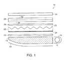
- FIG. 1illustrates a cross-sectional view of a backlighting system.
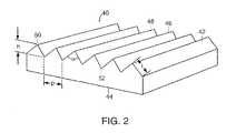
- FIG. 2illustrates a perspective view of a linear prism structure.
- FIG. 3illustrates a side view of the linear prism structure shown in FIG. 2 .
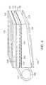
- FIG. 4illustrates a cross-sectional view of a second embodiment of a back lighting system.
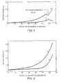
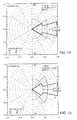
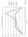
- FIG. 5shows a plot of reflectance as a function of angles of incidence and polarization for a moth-eye structure with 3,300 grooves per millimeter at a light wavelength of 514.5 nm.
- FIG. 6shows a plot of reflectance as a function of angles of incidence and polarization for a moth-eye structure with 3,300 grooves per millimeter at a light wavelength of 647.1 nm.
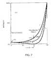
- FIG. 7shows a plot of reflectance for a dielectric having an index of refraction and a smooth non-moth-eye surface.
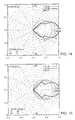
- FIG. 8shows a theoretical plot of output from a uniform light distribution X-profile for one and two films of 0.0019 inch (48 ⁇ m) pitch linear prisms having a prism angle of 90 degrees.
- FIG. 9shows a theoretical plot of output from a uniform light distribution Y-profile for one and two films of 0.0019 inch (48 ⁇ m) pitch linear prisms having a prism angle of 90 degrees.
- FIG. 10shows a theoretical plot of output from a uniform light distribution X-profile for one and two films of 0.0019 inch (48 ⁇ m) pitch linear prisms having a prism angle of 75 and 95 degrees, respectively.
- FIG. 11shows a theoretical plot of output from a uniform light distribution Y-profile for one and two films of 0.0019 inch (48 ⁇ m) pitch linear prisms having a prism angle of 75 and 95 degrees, respectively.
- FIG. 12shows a theoretical plot of output from a uniform light distribution X-profile for one and two films of 0.0019 inch (48 ⁇ m) linear prisms having a prism angle of 75 degrees.
- FIG. 13shows a theoretical plot of output from a uniform light distribution Y-profile for one and two films of 0.0019 inch (48 ⁇ m) linear prisms having a prism angle of 75 degrees.
- FIG. 14shows a theoretical plot of output from a cosine light distribution X-profile for one and two films of 0.0019 inch (48 ⁇ m) pitch linear prisms having a prism angle of 90 degrees.
- FIG. 15shows a theoretical plot of output from a cosine light distribution Y-profile for one and two films of 0.0019 inch (48 ⁇ m) pitch linear prisms having a prism angle of 90 degrees.
- FIG. 16shows a theoretical plot of output from a cosine light distribution X-profile for one and two films of 0.0019 inch (48 ⁇ m) pitch linear prisms having a prism angle of 75 and 95 degrees, respectively.
- FIG. 17shows a theoretical plot of output from a cosine light distribution Y-profile for one and two films of 0.0019 inch (48 ⁇ m) pitch linear prisms having a prism angle of 75 and 95 degrees, respectively.
- FIG. 18shows a theoretical plot of output from a cosine light, distribution X-profile for one and two films of 0.0019 inch (48 ⁇ m) linear prisms having a prism angle of 75 degrees.
- FIG. 19shows a theoretical plot of output from a cosine light distribution Y-profile for one and two films of 0.0019 inch (48 ⁇ m) linear prisms having a prism angle of 75 degrees.
- FIG. 20illustrates a side view of a subwavelength optical microstructure.
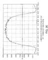
- FIG. 21shows a plot of relative response versus wavelength of light for a 0.002 inch (51 ⁇ m) thick film of polyester, 0.002 inch (51 ⁇ m) thick film of polyester with one side having moth-eye structures, 0.002 inch (51 ⁇ m) thick film of polyester with two sides having moth-eye structures, and a reference with a detector located normal to the surface of the film.
- FIG. 22shows a plot of relative response versus wavelength of light for a 0.002 inch (51 ⁇ m) thick film of polyester, 0.002 inch (51 ⁇ m) thick film of polyester with one side having moth-eye structures, 0.002 inch (51 ⁇ m) thick films of polyester with two sides having moth-eye structures, and a reference with a detector located at an angle 30 degrees from the normal to the surface of the film.
- FIG. 23shows a plot of light transmission versus angle from the normal of a 0.002 inch (51 ⁇ m) polyester film with and without a moth-eye structure on one side at the zero and 90 degree profile.
- FIG. 24shows a plot of color versus angle from the normal of a 0.002 inch (51 ⁇ m) thick polyester film with and without moth-eye structures on both sides observed at zero degree orientation.
- FIG. 25shows a plot of color versus angle from the normal of a 0.004 inch (102 ⁇ m) thick polyester film with and without moth-eye structures on both sides observed at zero degree X-orientation and 90 degree Y-orientation.
- FIG. 26is a plot of luminance cross section versus observation angle from the normal at zero degree orientation of a film with moth-eye structures having a period of about 0.2 ⁇ m and a height of about 0.4 ⁇ m and linear prisms with 95 degree included angle and a pitch of 0.0019 inches (48 ⁇ m).
- FIG. 27is a plot of luminance cross section versus observation angle from the normal at 90 degrees orientation of a film with moth-eye structures having a period of about 0.2 ⁇ m and a height of about 0.4 ⁇ m and linear prisms with a 95 degree included angle and a pitch of 0.0019 inches (48 ⁇ m).
- FIG. 28is a plot of luminance cross section versus observation angle from the normal at zero degree orientation of a film without moth-eye structures and linear prisms with 95 degree included angle and a pitch of 0.0019 inches (48 ⁇ m).
- FIG. 29is a plot of luminance cross section versus observation angle from the normal at zero degree orientation of a film without moth-eye structures and linear prisms with 95 degree included angle and a pitch of 0.0019 inches (48 ⁇ m).
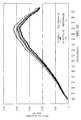
- FIG. 30shows a plot of light transmission versus angle from the normal of a film with 90 degree linear prisms having a pitch of 0.002 inches (51 ⁇ m) with and without moth-eye structures on the window side of the films.
- a back lighting system 10includes a light source 12 and light reflector 14 .
- Light source 12can be a fluorescent light, incandescent light or other suitable light source.
- Waveguide 16which is for directing light out of back lighting system, can be formed of a transparent solid material and is often wedge shaped.
- waveguide reflector 18On one side of waveguide 16 is waveguide reflector 18 formed of a specular material, such as aluminum or a coated white surface, for reflecting light back to waveguide 16 .
- Waveguide reflector 18can be curved or flat.
- Diffuser 20is a film that diffuses the light from the waveguide into a substantially uniform distribution.
- An example of a suitable diffuseris a randomly textured surface or gradient index film or engineered diffractive structure.
- first light-redirecting film 22has moth-eye structure 24 on a first side adjacent waveguide 16 .
- Second side of first light-redirecting film 22has prism structure 25 .
- An optional abrasion reduction layer 26is between first light-redirecting film 22 and second light-redirecting film 28 .
- the abrasion reduction layercan have a moth-eye structure on one or two surfaces to improve performance.
- Second light-redirecting film 28has moth-eye structure 30 on a first side adjacent first light-redirecting film 22 and prism structure 32 .
- Prism structure 32 of second light-redirecting film 28can be oriented in the same direction as the prisms on first light-redirecting film 22 . Alternatively, it may be offset by rotating the prism orientation up to about 180 degrees.
- the second light-redirecting filmis rotated about 90 degrees with respect to the first light-redirecting film to reduce moiré fringe formation and improve the uniformity of the exiting light distribution.
- a liquid crystal display 34 or display panelAbove the second light-redirecting film is a liquid crystal display 34 or display panel.
- a light-redirecting filmthat has linear prisms designed with a tilt, size, and included angle that match the light source, waveguide, and diffuser properties provides enhanced performance. Employing linear prism arrays with included angles that range from 95 degrees to 120 degrees provides a light distribution that is optimized for viewing angles of a computer screen. The included angle is considered the top angle of a triangular linear prism structure.
- a diffusercan also be positioned between the second light-redirecting film 28 and the display panel 34 .
- the moth-eye structures 24 , 30are linear moth-eye structures and can be oriented parallel or non-parallel to the respective linear prisms 25 , 32 in a horizontal orientation.
- longitudinal axes of the moth-eye structures 24are about perpendicular to longitudinal axes of the prisms 25
- longitudinal axes of the moth-eye structures 30are about perpendicular to longitudinal axes of the prisms 32 .
- the moth-eye structures 24are about perpendicular to the prisms 25
- the moth-eye structures 30are about parallel to the prisms 32 .
- the moth-eye structures 24are about parallel to the prisms 25 , while the moth-eye structures 30 are about perpendicular to the prisms 32 . In alternative embodiments, the moth-eye structures 24 , 30 are about parallel to respective prisms 25 , 32 . In further embodiments, the moth-eye structures 24 and/or 30 are oriented non-parallel and non-perpendicular to respective prisms 25 , 32 , depending on the desired optical properties.
- the linear moth-eye structuresare perpendicular to each other, the color is evident on two viewing axes that are perpendicular to each other. This latter result is the same as having regularly spaced 225 nm pitch two-dimensional structures (as compared to linear moth-eye structures) that produce color at wide-viewing angles in two axes that are perpendicular to each other.
- One reason for using linear moth-eye structuresis to control the direction at which the color can be viewed.
- the pitch of the moth-eye structuresis made to be less than about 180 nm, the resonant colors are not present at the wide-viewing angles and the need to use linear moth-eye structures is no longer present.
- the moth-eye structuresare linear, having a pitch between about 150 and 350 nanometers.
- Linear prism film 40has prism surface 42 and window surface 44 and is formed of a transparent polymeric material.
- Prisms 46have sides 48 with peaks 50 and valleys 52 .
- the pitch (p) of the prisms 46is measured from valley 52 to next valley 52 .
- the pitchcan be in the range of between 0.001 and 0.003 inches (25 and 76 ⁇ m).
- the height (h) of the linear prismsis measured by the vertical distance from the valley 52 to peak 50 .
- the heightcan be in the range of between 0.0003 and 0.0015 inches (7.6 and 38 ⁇ m).
- the included angle ( ⁇ )is measured between the two sides that meet at peak 50 .
- the angle ( ⁇ )can range from about 60 to 120 degrees. In a preferred embodiment, the angle ( ⁇ ) is in a range of between about 60 and 85 degrees or between about 95 and 120 degrees.
- Sides 48 on each side of the peak 50can be the side length (l) from valley 52 to peak 50 to form an isosceles triangle. Alternatively, the sides can have different lengths, thereby tilting or canting the prisms.
- the tilting angle ( ⁇ ) of the prismsis between the optical axis 54 and a line 56 perpendicular to the window side 44 .
- the prismscan be tilted in the range of between about ⁇ 44 and +44 degrees. In one embodiment, the tilting is about seven degrees.
- prism structures 22 , 32can include lenticular linear elements, such as disclosed in U.S. Pat. No. 5,592,332, issued to Nishio et al. on Jan. 7, 1997.
- a back lighting system 100includes a light source 102 and a light reflector 104 .
- Waveguide 106can be formed of a transparent solid material and can be wedge-shaped. Adjacent to the first side 108 of waveguide 106 is waveguide reflector 110 formed of a specular material. The reflector 110 is spaced slightly away from surface 108 to allow total internal reflection at surface 108 to take place. First side 108 can be stepped in shape. Second side 112 of waveguide 106 is on the opposite side away from waveguide reflector 110 . Second side 112 has moth-eye structures 114 .
- first light-redirecting film 116has first prism structure 118 with peaks 120 pointed toward waveguide 106 and first moth-eye structures 122 on the window side of first prism structure 118 .
- the peaks of linear prisms on first light-redirecting film 116run parallel to light source 102 .
- second light-redirecting film 124has second moth-eye structure 126 and second prism structure 128 .
- Peaks 130 of second prism structure 128point away from waveguide 106 .
- the peaks 130 of second prism structure 128are oriented in a non-parallel direction to peaks 120 of first prism structure 118 . A more preferred orientation is 90 degrees.
- the first moth-eye structures 122are oriented at about 90 degrees relative to the peaks of the linear prisms on the first light-redirecting film 116 .
- angle ( ⁇ ) of the linear prisms on the first light-redirecting film 116is about 88 degrees. In another embodiment, angle ( ⁇ ) is about 89 degrees.
- the second moth-eye structures 126can be oriented at about 90 degrees relative to the peaks of the second light-redirecting film 124 .
- angle ( ⁇ ) of the linear prisms on the light-redirecting film 116is about 88 degrees.
- angle ( ⁇ )is about 89 degrees.
- the moth-eye structures 122 , 126are oriented at about 90 degrees relative to the linear prisms of respective light-redirecting films 116 , 124 to minimize, and preferably eliminate, the deep blue to deep green color that is produced by light resonance, and which is visible, at wide entrance angles.
- TIRtotal internally reflecting
- BEFbrightness enhancing film
- BEFrightness enhancing film
- a further improvementcan be made by making the film monolithic or polylithic.
- a monolithic filmremoves one material interface (at the substrate) and improves optical transmission.
- a diffusercan be incorporated into the film structure, saving the need to fabricate a separate diffuser and dependent on the degree of collimation required.
- a fine pitch of a linear corner cube prism structureprovides excellent performance as a first layer in a back lighting system if a diffuser is not used between the top smooth surface of a waveguide and a flat surface of the linear micro corner cube sheet.
- a fine pitchpreferably in the range of between about 0.00005 and 0.0001 inches (1.3 and 2.5 ⁇ m), of the corner cube array helps to spread the refracted and retroreflected light by diffraction, creating increased diffusion of recycled light.
- the pitchis about 0.000075 inches (1.9 ⁇ m).
- the refracted and retroreflected lightis spread by one to two degrees, depending on the accuracy of the linear corner cube array dihedral angles.
- the second linear prism sheetis oriented about 90 degrees with respect to the first sheet.
- the materials that work well for optical microstructured filmsare ultraviolet-cured polymers bonded to a polyester substrate, which can have abrasion resistance which is important during handling of the light-redirecting films. If the prism tips are damaged during handling, the resulting display can have fine lines that appear as less bright than surrounding areas on axis and brighter than surrounding areas off-axis.
- the filmscan be formed of suitable polymers, such as polycarbonate.
- the filmscan be constructed from a polycarbonate material, acrylic, or other suitable material, such as disclosed in U.S. Pat. No. 5,396,350, issued to Beeson et al. on Mar. 7, 1995, the teachings of which are incorporated herein by reference.
- An abrasion reduction sheetingsuch as a thin polypropylene film or similar material, can be placed in between the light-redirecting film layers to help to reduce any effect from abrasion without losing significant brightness.
- Subwavelength visible light moth-eye structurescan be used on these overleaf films to effectively eliminate Fresnel reflection light losses.
- the softer filmsdo not abrade the linear prism peaks as easily as hard films.
- a semi-soft substratesuch as a polyvinyl chloride film, can be used in place of the polyester substrate to make light-redirecting films and reduce abrasion. However, one must be careful of out-gassing and resulting surface contamination that can occur with polyvinyl chloride.
- a linear non-isosceles prism array tilted or canted in the range of between about ⁇ 45 and +45 degrees and preferably at seven degrees, having a 95 degree included angle and a 0.0019 inch (48 ⁇ m) pitch as a first layer and a linear isosceles prism (with zero tilt), having a 95 degree included angle and a 0.0019 inch (48 ⁇ m) pitch as a second layercan significantly improve the amount of light that is directed through an AMLCD to the angles (geometry's) desired for optimum user viewing angles.
- the tilt or canting of the optical axis of the first layer linear prism arraycorrects the skewed direction of the light distribution coming from the waveguide and diffuser.
- a 0.0019 inch (48 ⁇ m) pitchcan cause diffraction spreading, which smooths the light distribution and maximizes the light directed toward the angles most beneficial or desired for a AMLCD display user.
- the 95 degree included anglefurther optimizes the field of view of the light distribution for the display user while still recycling light that is headed in the incorrect direction back into the display where it is used again.
- a preferred light-redirecting film combination for a wedge waveguideincludes a first light-redirecting film that has prisms tilted to correct for the skew created by the waveguide wedge and diffuser layers and has a prism angle designed to maximize the user field of view plus a second light-redirecting film oriented at 90 degrees to the first and with a symmetrical linear prism pattern.
- the prismscan be tilted uniformly in both directions (tilt every other prism in the opposite direction) to have a prism angle that optimizes the user field of view for this axis.
- the diffusercan be made by employing textured films and casting the linear prisms onto the smooth side of the film, by rotary screen printing a diffuse layer onto the polyester tie coat prior to casting the linear prisms onto the diffuse layer (in this embodiment the diffuse layer is sandwiched between the linear prisms and the substrate film), or by rotary screen printing a diffuse layer onto a carrier film and then casting linear prisms onto the diffuse layer.
- the prism and diffuse layercan be made of the same material and finish cured together, by adding particles into the tie coat prior to casting the linear prisms onto the tie coat, and by dispersing particles in the substrate sheet followed by casting linear prisms onto the substrate sheet.
- the addition of the moth-eye structure to the window side of the light-redirecting filmsincreases the system brightness by about 6% to 8%, which is significantly brighter (by 10% to 12%) than the previously known brightness-enhancing film systems with a similar pitch.
- the uniform white lightsuch as a fluorescent bulb that causes this light to have a cool appearance because of the blue shift, has distribution coming from the diffuser that is incident on the first layer moth-eye surface. At angles of incidence of +/ ⁇ 60 degrees, 2% or less of the light is reflected at the first layer moth-eye to air interface.
- Plots of the reflectanceare shown in FIGS. 5 and 6 for a subwavelength microstructure having 3,300 grooves per millimeter of light having wavelengths of 514.5 nm and 647.1 nm, respectively.
- the S linerepresents light perpendicular to the plane of incidence
- the P linerepresents light parallel to the plane of incidence. Shown in FIG.
- the average reflectance(linear average between S and P lines) is about 0.8% at 60 degrees and shown in FIG. 6 , the average reflectance is about 2% at 60 degrees. This is compared to an average of about 10% of the light that is reflected at a smooth non-moth-eye surface at a 60 degree angle of incidence.
- FIG. 7shows a plot of an average of about 10% reflectance at a 60 degree incident angle. Also at normal incidence, a typical 4% reflectance due to a smooth surface is reduced to less than 1% with a moth-eye structure.
- a green and then a blue colorcan be observed.
- the coloris a result of diffraction scattering as the short wavelengths enter the moth-eye structure from an angle that causes the aperture of the moth-eye elements to become diffractive and resonate.
- This diffraction scattered lightis processed by the linear prism film differently than the light that passes through a non-moth-eye smooth surface.
- the green to blue lightis more uniformly distributed throughout the film, creating a more uniform illumination.
- a significant amount of green lightis light piped by total internal reflection within the film and is partially filtered out of the light that becomes available to illuminate an LCD panel.
- Different size (frequency and amplitude) moth-eye structurescan be used to create different illumination effects depending on the light source and optical components used in the illumination system.
- the size of the moth-eye structures in the range from sub-wavelength to larger than wavelength scale structuresfor example, moth-eye structures having a period of between about 0.15 and 10.0 micrometers, the diffraction properties of the surface can be optimized to help smooth the resulting light distribution and improve wide angle light distribution.
- the lightAfter the light has passed through the first moth-eye layer, it is redirected in a collimating fashion to about 42 degrees, and the 95 degree linear prism second surface of the first film layer through refraction collimates the light to approximately +/ ⁇ 30 degrees. Then the light enters the moth-eye surface on the first surface of the second layer film where it is further collimated by refraction. The majority of the light is at +/ ⁇ 30 degrees from the normal as it enters the moth-eye surface and passes through the moth-eye layer with little intensity loss. The light passes through the second layer film and is further redirected through refraction and recycling by the 95 degree linear prism structure.
- the 95 degree prism shapehelps to recycle any of the light that is still traveling at wide angles of incidence. This light eventually emerges from the lighting system within a final +/ ⁇ 29 degree light distribution in both the X and Y axes.
- FIGS. 8 and 9show plots of output uniform light distribution of the X-profile and Y-profile, respectively, for one and two films of 0.0019 inch (48 ⁇ m) pitch for linear prisms having a prism angle of 90 degrees.
- FIGS. 8 and 9show plots of output uniform light distribution of the X-profile and Y-profile, respectively, for one and two films of 0.0019 inch (48 ⁇ m) pitch for linear prisms having a prism angle of 90 degrees.
- FIGS. 10 and 11show plots of output for uniform light distribution X-profile and Y-profile, respectively, for one and two films of 0.0019 inch (48 ⁇ m) pitch for linear prisms having a prism angle of 75 and 95 degrees, respectively.
- FIGS. 12 and 13show plots of output for uniform light distribution X-profile and Y-profile, respectively, for one and two films of 0.0019 inch (48 ⁇ m) linear prisms having a prism angle of 75 degrees.
- FIGS. 14 and 15show plots of output cosine light distribution of the X-profile and Y-profile, respectively, for one and two films of 0.0019 inch (48 ⁇ m) pitch for linear prisms having a prism angle of 90 degrees.
- FIGS. 16 and 17show plots of output for cosine light distribution X-profile and Y-profile, respectively, for one and two films of 0.0019 inch (48 ⁇ m) pitch for linear prisms having a prism angle of 75 and 95 degrees respectively.
- FIGS. 18 and 19show plots of output for cosine light distribution X-profile and Y-profile, respectively, for one and two films of 0.0019 inch (48 ⁇ m) linear prisms having a prism angle of 75 degrees. Additional optimization of the angles allows a near +/ ⁇ 10 degree intensity distribution.
- One disadvantage with this configurationis an approximate +/ ⁇ 2.0 degree void that appears at the center of the light intensity distribution. This effect is visible in FIGS. 12 and 13 . Slight curvature or positive-negative canting in the prism facets can reduce this void.
- the application of a moth-eye structure to the smooth surface of the linear prism filmssignificantly improves the light-redirecting capability of the films by increasing light throughput at the moth-eye structured surface and redirecting wide incident angle light rays. Diffraction effects also play a significant role in the improved performance of the system.
- the resulting color of the backlight assemblyis warmer in appearance than the same assembly without the addition of the moth-eye structures. This color shift can have a beneficial effect on the contrast within the final back light display.
- the moth-eye structure appliedpreferably has an amplitude (A) of about 0.4 micrometers and a period (P) of less than about 0.2 micrometers.
- the structureis sinusoidal in appearance and can provide a deep green to deep blue color when viewed at grazing angles of incidence.
- the amplitudeis about three times the period to provide a three to one aspect ratio.
- FIGS. 21 and 22show a plot of the improvement in transmission by wavelength for 0.002 inch (51 ⁇ m) thick PET having moth-eye structures on one side and having moth-eye structures on both sides at zero degrees and at 30 degree angles from the normal, respectively.
- the moth-eye structureshave a period of about 0.2 ⁇ m and a height of about 0.4 ⁇ m.
- the referenceis a uniform light distribution coming from a diffuser positioned above the waveguide.
- FIG. 23shows a plot of the improvement in transmission by angle from the normal for 0.002 inch (51 ⁇ m) PET with moth-eye structures. In this figure, the fluorescent tube light bulb is at a +80 degree position for the 90 degree orientation.
- FIG. 24shows a plot of the color shift which occurs for 0.002 inch (51 ⁇ m) thick PET with moth-eye structures on one side and with moth-eye structures on both sides.
- FIG. 25shows a plot of the color shift that occurs for 0.004 inch (102 ⁇ m) thick PET with 95 degree linear prisms on the side away from the diffuser and with and without moth eye on the side close to the diffuser.
- the sampleswere placed on top of the diffuser in a standard LCD back light assembly and the Photon Research detector, Model PR650, was supported eighteen inches (45.7 cm) above the part surface.
- the moth-eye structureprovides anti-reflection properties to the previously smooth light entrance surface of the substrate even at entrance angles that are near grazing incidence.
- the moth-eye structureis more effective than standard thin film anti-reflection coatings at wide angles of incidence, especially angles of incidence beyond 30 degrees up to 80 degrees. This characteristic causes many types of optical microstructure films, including linear prism films, to process light very differently than the standard linear prism light-redirecting films that have smooth entrance surfaces with or without standard anti-reflection thin film (vacuum deposited or liquid applied) coatings.
- the addition of the moth-eye structureshelps to more efficiently recycle light and also redirects the normally reflected grazing angle incidence rays into the optical microstructure (such as linear prisms) sheet where the rays are refracted, reflected or retroreflected depending on the respective angles of incidence.
- This moth-eye improvement conceptcan be added to many types of brightness enhancement films (BEF).
- BEFbrightness enhancement films
- a moth-eye anti-reflection surfaceis one in which the reflection of light is reduced by the presence of a regular array of small protuberances covering the surface. The spacing of the protuberances is less than the wavelength of light for which anti-reflection is sought.
- a moth-eye surfacecan be understood in terms of a surface layer in which the refractive index varies gradually from unity to that of the bulk material. Without such a layer the Fresnel reflection coefficient at an interface of two media is equal to ((n 1 ⁇ n 2 )/(n 1 +n 2 )) 2 , where n 1 and n 2 are the refractive indices of the media.
- net reflectancecan be regarded as the result of an infinite series of reflections at each incremental change in index. Since each reflection comes from a different depth from the surface, each has a different phase. If a transition takes place over an optical distance of ⁇ /2, all phases are present, there is destructive interference and the reflectance falls to zero.
- the interfaceappears relatively sharp and the reflectance is essentially that of a discontinuous boundary.
- Further increases in h/ ⁇show a series of successive maxima and minima, but the value does not again approach that of a sharp interface.
- the details of the curve shown in FIG. 20vary depending on the profile of the change of the index of refraction, but if the thickness is of the order of half a wavelength or more the reflectance is considerably reduced.
- the spacing of the protuberancesshould be sufficiently fine to avoid losses by diffraction. Preferably, it should be less than the shortest wavelength involved divided by the refractive index of the material.
- the arraycan act as a diffraction grating and, although there may well be a reduction in the specular reflection (zero order), the light is simply redistributed into the diffracted orders.
- d ⁇ for normal incidence and d ⁇ /2 for oblique incidence if for reflection onlyand that d ⁇ /2n in the case of transmission where diffraction inside the material is suppressed.
- the reflectanceis expected to be very low for wavelengths less than about 2.5h and greater than d at normal incidence, and for wavelengths greater than 2d for oblique incidence.
- the spacingis as close as possible, and the depth as great as possible, in order to give the widest possible bandwidth.
- a h/d ratiois preferably about three.
- the moth-eye effectshould not be confused with that of reducing the specular reflectance by roughening. Roughness merely redistributes the reflected light as diffuse scattering and degrades the transmitted wavefront. With the moth-eye structure, there is no increase in diffuse scattering, the transmitted wavefront is not degraded, and the reduction in reflection gives rise to a corresponding increase in transmission.
- the moth-eye structurehas many advantages. There is no extra coating process necessary.
- the structurecan be transferred to the sheet by a pressure molding process, such as with a Fresnel structure.
- the reflection reductiondoes not depend on the wavelength. There is only a lower limit (on the ultraviolet side of the spectrum) set by the structure period. If the wavelength is too small compared to the period, the light is diffracted. In regard to angular dependence, with conventional anti-reflective coatings, the transmission curve shifts with the light incidence angle. With the moth-eye structure, the critical wavelength for diffraction shifts to higher values, but there are no changes above this wavelength.
- Another advantage for moth-eye structuresis that there are no adhesion problems between lens and gradient layer because it can be one bulk material. From a high incident angle, the surfaces can appear blue or violet.
- the structureis first produced on a photoresist-covered glass substrate by a holographic exposure using an ultraviolet laser.
- a suitable deviceis available from Holographic Lithography Systems of Bedford, Mass. 01730.
- An example of a methodis disclosed in U.S. Pat. No. 4,013,465, issued to Clapham et al. on Mar. 22, 1977, the teachings of which are incorporated herein by reference. This method is sensitive to any changes in the environment, such as temperature and dust, and care must taken.
- the structureis then transferred to a nickel shim by an electroforming process. In a preferred embodiment, the shims are about 300 micrometers thick or less.
- the moth-eye structurescan be made one dimensional in a grating type pattern.
- the structurehas a nearly rectangular profile, which means they have no gradient layers, but more of a one layer anti-reflective coating with a lowered refractive index in the structure region.
- Control of the grating depthis important as is control of thickness for the evaporated layers. Control of depth and thickness is achieved by maintaining uniformity of beam exposure, substrate flatness, and exposure time.
- a two-dimensional structureis formed by two exposures with a linear sinus-grid, turned by 90 degrees for the second exposure.
- a third type of structureis formed by three exposures with turns of 60 degrees to provide a hexagonal or honeycomb shape.
- the results with two 95 degree linear prism films each having a moth-eye structure on the previously smooth sideshow about the same brightness on axis as two 90 degree BEF films, a large improvement in brightness off axis in both vertical and horizontal axis and a warmer color to the light emerging from the display.
- the total integrated light intensity for the 95 degree prisms with moth-eye structure filmsis 6,686.8 lm/m 2 with a maximum of 4,460 cd/m 2 and a minimum of 554.0 cd/m 2 .
- the integrated light intensityis 5,698.8 lm/m 2 with a maximum of 4,685.0 cd/M 2 and a minimum of 295.9 cd/m 2 .
- a preferred embodimentincludes a 75 degree linear prism film that can be used as the first layer above a uniform light output diffuser to collimate the light to about a +/ ⁇ 30 degree angle.
- the prism grooves in this first layerare oriented parallel to the light source that illuminates the waveguide that is below the diffuser.
- On top of this filmcan be a 95 degree linear prism film that is oriented at 90 degrees with respect to the 75 degree film to collimate the light to about +/ ⁇ 25 degrees with a small percentage of the light at +/ ⁇ 30 degrees, as shown in FIGS. 10 , 11 , 16 and 17 .
- the final intensity of the collimated lightis excellent and comparable to results obtained with two crossed 90 degrees BEF films, as shown in FIGS.
- FIG. 30shows a comparative plot of light transmission versus angle from the normal of a film with 90 degree linear prisms having a pitch of 0.002 inches (51 ⁇ m) with moth-eye structures on the window side of the film and a film with 90 degree linear prisms having a pitch of 0.002 inches (51 ⁇ m) without moth-eye structures on the side of the film.
- the comparative plotshows a substantial improvement in transmission, particularly at zero degrees, when employing a moth-eye structure on the window side of the film as compared to a similar film without a moth-eye structure.
Landscapes
- Physics & Mathematics (AREA)
- General Physics & Mathematics (AREA)
- Optics & Photonics (AREA)
- Optical Elements Other Than Lenses (AREA)
Abstract
Description
Claims (41)
Priority Applications (1)
| Application Number | Priority Date | Filing Date | Title |
|---|---|---|---|
| US10/445,375US6891677B2 (en) | 1999-11-12 | 2003-05-23 | Subwavelength optical microstructure light-redirecting films |
Applications Claiming Priority (3)
| Application Number | Priority Date | Filing Date | Title |
|---|---|---|---|
| US09/438,912US6356389B1 (en) | 1999-11-12 | 1999-11-12 | Subwavelength optical microstructure light collimating films |
| US09/684,455US6570710B1 (en) | 1999-11-12 | 2000-10-06 | Subwavelength optical microstructure light collimating films |
| US10/445,375US6891677B2 (en) | 1999-11-12 | 2003-05-23 | Subwavelength optical microstructure light-redirecting films |
Related Parent Applications (1)
| Application Number | Title | Priority Date | Filing Date |
|---|---|---|---|
| US09/684,455Continuation-In-PartUS6570710B1 (en) | 1999-11-12 | 2000-10-06 | Subwavelength optical microstructure light collimating films |
Publications (2)
| Publication Number | Publication Date |
|---|---|
| US20040027676A1 US20040027676A1 (en) | 2004-02-12 |
| US6891677B2true US6891677B2 (en) | 2005-05-10 |
Family
ID=27031845
Family Applications (2)
| Application Number | Title | Priority Date | Filing Date |
|---|---|---|---|
| US09/684,455Expired - Fee RelatedUS6570710B1 (en) | 1999-11-12 | 2000-10-06 | Subwavelength optical microstructure light collimating films |
| US10/445,375Expired - Fee RelatedUS6891677B2 (en) | 1999-11-12 | 2003-05-23 | Subwavelength optical microstructure light-redirecting films |
Family Applications Before (1)
| Application Number | Title | Priority Date | Filing Date |
|---|---|---|---|
| US09/684,455Expired - Fee RelatedUS6570710B1 (en) | 1999-11-12 | 2000-10-06 | Subwavelength optical microstructure light collimating films |
Country Status (5)
| Country | Link |
|---|---|
| US (2) | US6570710B1 (en) |
| EP (1) | EP1248958A2 (en) |
| JP (1) | JP2003518263A (en) |
| CN (1) | CN1278139C (en) |
| WO (1) | WO2001035128A2 (en) |
Cited By (45)
| Publication number | Priority date | Publication date | Assignee | Title |
|---|---|---|---|---|
| US20040202001A1 (en)* | 2003-02-12 | 2004-10-14 | Roberts John K. | Vehicle information displays |
| US20060227323A1 (en)* | 2005-03-16 | 2006-10-12 | Dai Nippon Printing Co., Ltd. | Converging sheet, surface light source unit, and transmission type display |
| US20080101759A1 (en)* | 2006-10-26 | 2008-05-01 | K Laser Technology, Inc. | Prism matrix with random phase structures |
| US20080175021A1 (en)* | 2004-06-18 | 2008-07-24 | Chi Mei Optoelectronics Corp. | Flat panel display |
| US20090147361A1 (en)* | 2007-12-07 | 2009-06-11 | 3M Innovative Properties Company | Microreplicated films having diffractive features on macro-scale features |
| US20090262192A1 (en)* | 1995-05-22 | 2009-10-22 | Donnelly Corporation | Vehicular vision system |
| US20090283807A1 (en)* | 2008-05-14 | 2009-11-19 | International Business Machines Corporation | Anti-Reflection Structures For CMOS Image Sensors |
| US20090286346A1 (en)* | 2008-05-14 | 2009-11-19 | International Business Machines Corporation | Methods For Forming Anti-Reflection Structures For CMOS Image Sensors |
| US20110019260A1 (en)* | 2002-09-20 | 2011-01-27 | Donnelly Corporation | Vehicular electrochromic interior rearview mirror assembly |
| US20110045172A1 (en)* | 1994-05-05 | 2011-02-24 | Donnelly Corporation | Method of forming a mirrored bent cut glass shape for vehicular exterior rearview mirror assembly |
| US20110085232A1 (en)* | 2009-10-08 | 2011-04-14 | The Penn State Research Foundation | Multi-spectral filters, mirrors and anti-reflective coatings with subwavelength periodic features for optical devices |
| US20110084198A1 (en)* | 2002-09-20 | 2011-04-14 | Donnelly Corporation | Interior rearview mirror information display system for a vehicle |
| US20110096387A1 (en)* | 2002-09-20 | 2011-04-28 | Donnelly Corporation | Reflective mirror assembly |
| US20110128137A1 (en)* | 1994-05-05 | 2011-06-02 | Donnelly Corporation | Vehicular blind spot indicator mirror |
| US20110141765A1 (en)* | 2009-12-15 | 2011-06-16 | Industrial Technology Research Institute | Planar light source module and optical film |
| US20110149403A1 (en)* | 2009-12-18 | 2011-06-23 | Soon-Ryong Park | Anti-reflection film and display device including the same, and manufacturing method of anti-reflection film and master film therefor |
| US20110166779A1 (en)* | 1999-11-24 | 2011-07-07 | Donnelly Corporation | Interior rearview mirror system |
| US20110291993A1 (en)* | 2009-05-28 | 2011-12-01 | Shinichi Miyazaki | Touch panel, liquid crystal panel, liquid crystal display device, and touch panel-integrated liquid crystal display device |
| US8162493B2 (en) | 1999-11-24 | 2012-04-24 | Donnelly Corporation | Interior rearview mirror assembly for vehicle |
| US8170748B1 (en) | 2003-10-14 | 2012-05-01 | Donnelly Corporation | Vehicle information display system |
| US8177376B2 (en) | 2002-06-06 | 2012-05-15 | Donnelly Corporation | Vehicular interior rearview mirror system |
| US8179236B2 (en) | 2000-03-02 | 2012-05-15 | Donnelly Corporation | Video mirror system suitable for use in a vehicle |
| US8194133B2 (en) | 2000-03-02 | 2012-06-05 | Donnelly Corporation | Vehicular video mirror system |
| US20120154712A1 (en)* | 2010-12-16 | 2012-06-21 | Shang-Wen Yu | Liquid crystal display device and backlight module thereof |
| US8267559B2 (en) | 1997-08-25 | 2012-09-18 | Donnelly Corporation | Interior rearview mirror assembly for a vehicle |
| US8271187B2 (en) | 2000-03-02 | 2012-09-18 | Donnelly Corporation | Vehicular video mirror system |
| US8282226B2 (en) | 2002-06-06 | 2012-10-09 | Donnelly Corporation | Interior rearview mirror system |
| US8282253B2 (en) | 2004-11-22 | 2012-10-09 | Donnelly Corporation | Mirror reflective element sub-assembly for exterior rearview mirror of a vehicle |
| US8288711B2 (en) | 1998-01-07 | 2012-10-16 | Donnelly Corporation | Interior rearview mirror system with forwardly-viewing camera and a control |
| US8294975B2 (en) | 1997-08-25 | 2012-10-23 | Donnelly Corporation | Automotive rearview mirror assembly |
| US8304711B2 (en) | 2002-05-03 | 2012-11-06 | Donnelly Corporation | Vehicle rearview mirror system |
| US8309907B2 (en) | 1997-08-25 | 2012-11-13 | Donnelly Corporation | Accessory system suitable for use in a vehicle and accommodating a rain sensor |
| US8325028B2 (en) | 1998-01-07 | 2012-12-04 | Donnelly Corporation | Interior rearview mirror system |
| US8379289B2 (en) | 2003-10-02 | 2013-02-19 | Donnelly Corporation | Rearview mirror assembly for vehicle |
| US8427288B2 (en) | 2000-03-02 | 2013-04-23 | Donnelly Corporation | Rear vision system for a vehicle |
| US8503062B2 (en) | 2005-05-16 | 2013-08-06 | Donnelly Corporation | Rearview mirror element assembly for vehicle |
| US8508383B2 (en) | 2008-03-31 | 2013-08-13 | Magna Mirrors of America, Inc | Interior rearview mirror system |
| US8508384B2 (en) | 2003-05-19 | 2013-08-13 | Donnelly Corporation | Rearview mirror assembly for vehicle |
| US8525703B2 (en) | 1998-04-08 | 2013-09-03 | Donnelly Corporation | Interior rearview mirror system |
| US8653959B2 (en) | 2001-01-23 | 2014-02-18 | Donnelly Corporation | Video mirror system for a vehicle |
| US8779910B2 (en) | 1997-08-25 | 2014-07-15 | Donnelly Corporation | Interior rearview mirror system |
| US10036831B2 (en) | 2011-08-17 | 2018-07-31 | 3M Innovative Properties Company | Nanostructured articles and methods to make the same |
| US10739513B2 (en) | 2018-08-31 | 2020-08-11 | RAB Lighting Inc. | Apparatuses and methods for efficiently directing light toward and away from a mounting surface |
| US10801679B2 (en) | 2018-10-08 | 2020-10-13 | RAB Lighting Inc. | Apparatuses and methods for assembling luminaires |
| US11124932B1 (en)* | 2021-04-30 | 2021-09-21 | Mark Joseph O'Neill | Retroreflective traffic stripe for both dry and wet weather conditions |
Families Citing this family (81)
| Publication number | Priority date | Publication date | Assignee | Title |
|---|---|---|---|---|
| WO2000008494A1 (en)* | 1998-08-05 | 2000-02-17 | Mitsubishi Rayon Co., Ltd. | Lens sheet and method for producing the same |
| TW475334B (en)* | 2000-07-14 | 2002-02-01 | Light Opto Electronics Co Ltd | High light-sensing efficiency image sensor apparatus and method of making the same |
| KR100514011B1 (en)* | 2000-07-24 | 2005-09-13 | 미츠비시 레이온 가부시키가이샤 | Surface illuminant device and prism sheet used therefor |
| US20040190102A1 (en)* | 2000-08-18 | 2004-09-30 | Mullen Patrick W. | Differentially-cured materials and process for forming same |
| EP1309437B1 (en)* | 2000-08-18 | 2006-03-01 | Reflexite Corporation | Differentially cured materials and process for forming same |
| US7230764B2 (en)* | 2000-08-18 | 2007-06-12 | Reflexite Corporation | Differentially-cured materials and process for forming same |
| DE10134722A1 (en)* | 2001-07-17 | 2003-02-06 | Siemens Ag | Instrument cluster with a liquid crystal display with a reflector on the back |
| AU2002327420B2 (en)* | 2001-08-06 | 2007-05-31 | Mei, Incorporated | Document validator subassembly |
| JP3785093B2 (en)* | 2001-12-28 | 2006-06-14 | アルプス電気株式会社 | Light guide plate, manufacturing method therefor, lighting device, and liquid crystal display device |
| KR100951285B1 (en)* | 2002-03-06 | 2010-04-02 | 키모토 컴파니 리미티드 | Light diffusion sheet and surface light source element |
| WO2003091794A1 (en)* | 2002-04-24 | 2003-11-06 | Nitto Denko Corporation | Light converging system and transmission liquid crystal display |
| DE10223165A1 (en)* | 2002-05-24 | 2003-12-18 | Siemens Ag | Optical display device |
| KR100911232B1 (en)* | 2002-06-11 | 2009-08-06 | 쓰리엠 이노베이티브 프로퍼티즈 캄파니 | Master manufacturing method and retroreflective seating |
| US6843571B2 (en) | 2002-06-11 | 2005-01-18 | 3M Innovative Properties Company | Methods of making a master and replicas thereof |
| FR2843792B1 (en)* | 2002-08-20 | 2005-04-08 | Thales Sa | HIGH LUMINANCE LIGHT BOX FOR VISUALIZATIONS |
| JP2004177806A (en)* | 2002-11-28 | 2004-06-24 | Alps Electric Co Ltd | Anti-reflection structure, lighting device, liquid crystal display device, and anti-reflection coating molding die |
| US6888676B2 (en)* | 2003-03-20 | 2005-05-03 | Nokia Corporation | Method of making polarizer and antireflection microstructure for mobile phone display and window |
| SE526044C2 (en)* | 2003-03-21 | 2005-06-21 | Sectra Mamea Ab | A refractive X-ray element |
| EP1625430A2 (en) | 2003-05-02 | 2006-02-15 | Reflexite Corporation | Light-redirecting optical structures |
| US7021797B2 (en)* | 2003-05-13 | 2006-04-04 | Light Prescriptions Innovators, Llc | Optical device for repositioning and redistributing an LED's light |
| US6997595B2 (en)* | 2003-08-18 | 2006-02-14 | Eastman Kodak Company | Brightness enhancement article having trapezoidal prism surface |
| US20050057913A1 (en)* | 2003-09-16 | 2005-03-17 | Dennis Brett M. | Backlight having multiple intensity maxima |
| JP2005135899A (en)* | 2003-10-06 | 2005-05-26 | Omron Corp | Surface light source apparatus and display apparatus |
| KR20050090203A (en)* | 2004-03-08 | 2005-09-13 | 삼성전자주식회사 | Optical member, back light assembly having the same and display device having the same |
| JP2005265894A (en)* | 2004-03-16 | 2005-09-29 | Fuji Photo Film Co Ltd | Condensing filter |
| EA011968B1 (en) | 2004-04-30 | 2009-06-30 | Де Ля Рю Интернэшнл Лимитед | Security devices |
| KR101245946B1 (en)* | 2004-06-17 | 2013-03-21 | 쓰리엠 이노베이티브 프로퍼티즈 컴파니 | Optical film, assembly and display device |
| US7351346B2 (en) | 2004-11-30 | 2008-04-01 | Agoura Technologies, Inc. | Non-photolithographic method for forming a wire grid polarizer for optical and infrared wavelengths |
| JP2008522226A (en)* | 2004-11-30 | 2008-06-26 | アグーラ テクノロジーズ インコーポレイテッド | Application and fabrication technology of large-scale wire grid polarizer |
| GB0427607D0 (en)* | 2004-12-16 | 2005-01-19 | Microsharp Corp Ltd | Structured optical film |
| US7430358B2 (en)* | 2005-04-20 | 2008-09-30 | Wavefront Technology, Inc. | Elliptical diffusers used in displays |
| TWI264578B (en)* | 2005-04-22 | 2006-10-21 | Ind Tech Res Inst | Microstructure light modulation element and device |
| US7529026B2 (en)* | 2005-04-28 | 2009-05-05 | Hewlett-Packard Development Company, L.P. | Optical system with nanoscale projection antireflection layer/embossing |
| US20070110386A1 (en)* | 2005-11-12 | 2007-05-17 | Tien-Hon Chiang | Device having combined diffusing, collimating, and color mixing light control function |
| US20070115554A1 (en)* | 2005-11-22 | 2007-05-24 | Breitung Eric M | Antireflective surfaces, methods of manufacture thereof and articles comprising the same |
| US20070116934A1 (en)* | 2005-11-22 | 2007-05-24 | Miller Scott M | Antireflective surfaces, methods of manufacture thereof and articles comprising the same |
| EP1793263A1 (en) | 2005-12-01 | 2007-06-06 | Emphasis Materials, Inc. | Light intensity and/or colour distribution correcting element for an illumination system whose function is correlated to the incident light distribution |
| CN100454043C (en)* | 2005-12-16 | 2009-01-21 | 群康科技(深圳)有限公司 | Brightness enhancement film, backlight module and liquid crystal display module |
| US7366393B2 (en)* | 2006-01-13 | 2008-04-29 | Optical Research Associates | Light enhancing structures with three or more arrays of elongate features |
| US7674028B2 (en) | 2006-01-13 | 2010-03-09 | Avery Dennison Corporation | Light enhancing structures with multiple arrays of elongate features of varying characteristics |
| US20070086207A1 (en)* | 2006-01-13 | 2007-04-19 | Optical Research Associates | Display systems including light enhancing structures with arrays of elongate features |
| US7866871B2 (en) | 2006-01-13 | 2011-01-11 | Avery Dennison Corporation | Light enhancing structures with a plurality of arrays of elongate features |
| JP4006650B1 (en)* | 2006-05-08 | 2007-11-14 | ソニー株式会社 | Optical film, method for producing the same, and display device |
| US7677146B2 (en)* | 2006-05-10 | 2010-03-16 | 3M Innovative Properties Company | Cutting tool using one or more machined tool tips in a continuous or interrupted cut fast tool servo |
| US7950838B2 (en)* | 2006-05-31 | 2011-05-31 | 3M Innovative Properties Company | Light directing film |
| EP2049365B1 (en) | 2006-08-01 | 2017-12-13 | 3M Innovative Properties Company | Illumination device |
| US20080129930A1 (en)* | 2006-12-01 | 2008-06-05 | Agoura Technologies | Reflective polarizer configuration for liquid crystal displays |
| JP4320672B2 (en)* | 2006-12-06 | 2009-08-26 | ソニー株式会社 | Optical sheet and display device |
| US7628100B2 (en)* | 2007-01-05 | 2009-12-08 | 3M Innovative Properties Company | Cutting tool using one or more machined tool tips with diffractive features in a continuous or interrupted cut fast tool servo |
| US9337373B2 (en) | 2007-05-01 | 2016-05-10 | Morgan Solar Inc. | Light-guide solar module, method of fabrication thereof, and panel made therefrom |
| EP2174058A4 (en)* | 2007-05-01 | 2011-10-26 | Morgan Solar Inc | LIGHTING DEVICE |
| US9040808B2 (en)* | 2007-05-01 | 2015-05-26 | Morgan Solar Inc. | Light-guide solar panel and method of fabrication thereof |
| US20090071537A1 (en)* | 2007-09-17 | 2009-03-19 | Ozgur Yavuzcetin | Index tuned antireflective coating using a nanostructured metamaterial |
| JP5348452B2 (en)* | 2007-09-27 | 2013-11-20 | 群創光電股▲ふん▼有限公司 | Backlight for dual view display |
| US7847886B2 (en)* | 2007-10-03 | 2010-12-07 | Reflexite Corporation | Parabolic lenticular collimating films and methods thereof |
| US7669508B2 (en)* | 2007-10-29 | 2010-03-02 | 3M Innovative Properties Company | Cutting tool using one or more machined tool tips with diffractive features |
| JP2009199001A (en)* | 2008-02-25 | 2009-09-03 | Fujifilm Corp | Laminated film for prism sheet, prism sheet and display device |
| CN106154399A (en)* | 2008-04-02 | 2016-11-23 | 3M创新有限公司 | Light directing film and preparation method thereof |
| US20110181971A1 (en)* | 2008-04-02 | 2011-07-28 | Campbell Alan B | Methods and systems for fabricating optical films having superimposed features |
| US8317360B2 (en)* | 2008-09-18 | 2012-11-27 | Guardian Industries Corp. | Lighting system cover including AR-coated textured glass, and method of making the same |
| KR101621013B1 (en)* | 2008-12-09 | 2016-05-16 | 삼성디스플레이 주식회사 | Display device |
| JP5510865B2 (en)* | 2009-03-25 | 2014-06-04 | 住友化学株式会社 | Anti-glare treatment method, anti-glare film manufacturing method and mold manufacturing method |
| JP2010272612A (en)* | 2009-05-20 | 2010-12-02 | Sony Corp | Solid-state imaging device, method of manufacturing the same, and imaging device |
| JP2010271533A (en)* | 2009-05-21 | 2010-12-02 | Canon Inc | Optical element and optical system having the same |
| KR101614898B1 (en)* | 2009-08-17 | 2016-04-25 | 삼성디스플레이 주식회사 | Optical sheet and tiled display using the same |
| US8130341B2 (en)* | 2009-08-25 | 2012-03-06 | Sharp Kabushiki Kaisha | Uniform diffractive backlight |
| US8353617B2 (en)* | 2009-09-03 | 2013-01-15 | Sharp Kabushiki Kaisha | Backlight |
| EP2733522B1 (en) | 2009-10-28 | 2021-06-09 | Schott AG | Display unit |
| US8538224B2 (en)* | 2010-04-22 | 2013-09-17 | 3M Innovative Properties Company | OLED light extraction films having internal nanostructures and external microstructures |
| US8885995B2 (en) | 2011-02-07 | 2014-11-11 | Morgan Solar Inc. | Light-guide solar energy concentrator |
| KR101208022B1 (en)* | 2011-05-24 | 2012-12-05 | 삼성코닝정밀소재 주식회사 | Optical film for reducing color shift and lcd device having the same |
| EP2543540A1 (en)* | 2011-07-07 | 2013-01-09 | Odelo GmbH | Optical fibre, illuminant and motor vehicle light |
| US8328403B1 (en) | 2012-03-21 | 2012-12-11 | Morgan Solar Inc. | Light guide illumination devices |
| US10260704B2 (en)* | 2013-05-28 | 2019-04-16 | Honda Motor Co., Ltd. | Vehicle lamp |
| KR102267204B1 (en)* | 2013-10-02 | 2021-06-22 | 쓰리엠 이노베이티브 프로퍼티즈 컴파니 | Microstructured diffuser comprising first microstructured layer and coating, optical stacks, and method |
| KR101526792B1 (en)* | 2014-03-06 | 2015-06-05 | 현대자동차주식회사 | Back light unit for outside mirror of vehicle |
| IL235642B (en)* | 2014-11-11 | 2021-08-31 | Lumus Ltd | Compact head-mounted display system protected by a hyperfine structure |
| CN105372733B (en)* | 2015-12-01 | 2018-03-09 | 上海交通大学 | Reflective membrane and its preparation technology with moth ocular structure |
| CN107390307A (en)* | 2016-05-16 | 2017-11-24 | 惠和株式会社 | The manufacture method of liquid crystal display optical sheet, back light for liquid crystal display device unit and liquid crystal display optical sheet |
| US11726266B2 (en)* | 2019-06-28 | 2023-08-15 | 3M Innovative Properties Company | Structured surface and optical ferrule including same |
| WO2021161128A1 (en)* | 2020-02-10 | 2021-08-19 | 3M Innovative Properties Company | Backlight for display |
Citations (79)
| Publication number | Priority date | Publication date | Assignee | Title |
|---|---|---|---|---|
| GB198279A (en)* | 1922-09-23 | 1923-05-31 | Alfred Cave | Improvements in or relating to apparatus for use in cutting cheese and other plastic or semi-solid substances |
| US2218227A (en) | 1938-04-02 | 1940-10-15 | Douglas F Winnek | Method for embossing sheet plastic material |
| US2232551A (en) | 1936-01-10 | 1941-02-18 | Merton Thomas Ralph | Method of preparing diffractive foils and other bodies with diffractive surfaces |
| US2248638A (en) | 1937-02-22 | 1941-07-08 | Merton Thomas Ralph | Sheet material with prismatic surfaces |
| US2310790A (en) | 1943-02-09 | Optical reflecting material | ||
| US2474317A (en) | 1949-06-28 | Light refracting and transmitting | ||
| US3234376A (en) | 1963-02-11 | 1966-02-08 | Michael J Ceglia | Glare-free lighting fixture |
| US3288990A (en) | 1964-09-25 | 1966-11-29 | K S H Plastics Inc | Panel |
| FR2049387A6 (en) | 1969-06-09 | 1971-03-26 | Nec | |
| US3846012A (en) | 1973-11-14 | 1974-11-05 | Qantix Corp | Transparent front projection screen having concave ridges thereon |
| US3908056A (en) | 1973-09-10 | 1975-09-23 | Minnesota Mining & Mfg | Optically decorative web |
| US4013465A (en) | 1973-05-10 | 1977-03-22 | Secretary Of State For Defence In Her Britannic Majesty's Government Of The United Kingdom Of Great Britain And Northern Ireland | Reducing the reflectance of surfaces to radiation |
| US4064433A (en) | 1976-06-30 | 1977-12-20 | K-S-H, Inc. | Prismatic lighting panel |
| US4114983A (en) | 1977-02-18 | 1978-09-19 | Minnesota Mining And Manufacturing Company | Polymeric optical element having antireflecting surface |
| US4120565A (en) | 1977-06-16 | 1978-10-17 | The United States Of America As Represented By The United States Department Of Energy | Prisms with total internal reflection as solar reflectors |
| GB1529021A (en)* | 1977-03-24 | 1978-10-18 | Secretary Industry Brit | Double glazed windows |
| US4154219A (en) | 1977-03-11 | 1979-05-15 | E-Systems, Inc. | Prismatic solar reflector apparatus and method of solar tracking |
| US4233651A (en) | 1978-03-30 | 1980-11-11 | Keene Corporation | Work area lighting system |
| US4242723A (en) | 1979-05-14 | 1980-12-30 | Keene Corporation | Low level work area lighting system |
| US4260220A (en) | 1979-06-15 | 1981-04-07 | Canadian Patents And Development Limited | Prism light guide having surfaces which are in octature |
| US4340276A (en) | 1978-11-01 | 1982-07-20 | Minnesota Mining And Manufacturing Company | Method of producing a microstructured surface and the article produced thereby |
| US4414316A (en) | 1980-09-05 | 1983-11-08 | Rexham Corporation | Composite lenticular screen sheet |
| US4420502A (en) | 1980-09-05 | 1983-12-13 | Conley Kenneth E | Apparatus and method for producing a flexible sheet material having a predetermined surface characteristic |
| US4497860A (en) | 1978-12-18 | 1985-02-05 | Minnesota Mining And Manufacturing Company | Imageable prismatic array |
| US4542449A (en) | 1983-08-29 | 1985-09-17 | Canadian Patents & Development Limited | Lighting panel with opposed 45° corrugations |
| US4576850A (en) | 1978-07-20 | 1986-03-18 | Minnesota Mining And Manufacturing Company | Shaped plastic articles having replicated microstructure surfaces |
| US4615579A (en) | 1983-08-29 | 1986-10-07 | Canadian Patents & Development Ltd. | Prism light guide luminaire |
| US4668558A (en) | 1978-07-20 | 1987-05-26 | Minnesota Mining And Manufacturing Company | Shaped plastic articles having replicated microstructure surfaces |
| US4750798A (en)* | 1983-08-29 | 1988-06-14 | Canadian Patents And Developement Limited | Prism light guide luminaire |
| US4787708A (en) | 1987-05-08 | 1988-11-29 | Tir Systems Ltd. | Apparatus for continuously controlled emission of light from prism light guide |
| US4805984A (en) | 1985-11-21 | 1989-02-21 | Minnesota Mining And Manufacturing Company | Totally internally reflecting light conduit |
| US4883341A (en) | 1987-04-24 | 1989-11-28 | Tir Systems Ltd | Non-reflective graphic surface |
| US4906070A (en) | 1985-11-21 | 1990-03-06 | Minnesota Mining And Manufacturing Company | Totally internally reflecting thin, flexible film |
| EP0414313A1 (en)* | 1989-08-22 | 1991-02-27 | Koninklijke Philips Electronics N.V. | Rear projection screen and rear projection system comprising such a screen |
| US5056892A (en) | 1985-11-21 | 1991-10-15 | Minnesota Mining And Manufacturing Company | Totally internally reflecting thin, flexible film |
| US5079675A (en)* | 1990-11-08 | 1992-01-07 | Deilaito Co., Ltd. | Surface illuminating apparatus |
| US5126882A (en) | 1987-11-12 | 1992-06-30 | Mitsubishi Rayon Co., Ltd. | Plane light source unit |
| US5177637A (en) | 1990-09-11 | 1993-01-05 | Nikon Corporation | Focusing screen including different height microlenses arranged in a cyclical pattern |
| US5183597A (en) | 1989-02-10 | 1993-02-02 | Minnesota Mining And Manufacturing Company | Method of molding microstructure bearing composite plastic articles |
| US5186530A (en) | 1991-11-22 | 1993-02-16 | Tir Systems, Ltd. | Lighting structure having variable transmissivity internal light guide illumination |
| US5339179A (en)* | 1992-10-01 | 1994-08-16 | International Business Machines Corp. | Edge-lit transflective non-emissive display with angled interface means on both sides of light conducting panel |
| US5396350A (en)* | 1993-11-05 | 1995-03-07 | Alliedsignal Inc. | Backlighting apparatus employing an array of microprisms |
| EP0685681A2 (en)* | 1994-05-31 | 1995-12-06 | SANYO ELECTRIC Co., Ltd. | Solar lighting apparatus and controller for said apparatus |
| WO1996010148A1 (en)* | 1994-09-27 | 1996-04-04 | Minnesota Mining And Manufacturing Company | Luminance control film |
| US5550676A (en)* | 1990-09-12 | 1996-08-27 | Mitsubishi Rayon Co., Ltd | Surface light source element |
| TW289802B (en) | 1994-08-12 | 1996-11-01 | Dainippon Printing Co Ltd | |
| US5581605A (en) | 1993-02-10 | 1996-12-03 | Nikon Corporation | Optical element, production method of optical element, optical system, and optical apparatus |
| US5592332A (en) | 1992-12-25 | 1997-01-07 | Dai Nippon Printing Co., Ltd. | Renticular lens, surface light source, and liquid crystal display apparatus |
| US5600462A (en) | 1992-09-16 | 1997-02-04 | International Business Machines Corporation | Optical film and liquid crystal display device using the film |
| US5629784A (en)* | 1994-04-12 | 1997-05-13 | Ois Optical Imaging Systems, Inc. | Liquid crystal display with holographic diffuser and prism sheet on viewer side |
| US5629796A (en) | 1992-01-13 | 1997-05-13 | Central Research Laboratories Limited | Image frame |
| US5644431A (en) | 1990-05-18 | 1997-07-01 | University Of Arkansas, N.A. | Directional image transmission sheet and method of making same |
| WO1997028468A1 (en)* | 1996-02-05 | 1997-08-07 | Minnesota Mining And Manufacturing Company | Brightness enhancement film with soft cutoff |
| US5694246A (en) | 1994-01-03 | 1997-12-02 | Omron Corporation | Method of manufacturing lens array |
| TW325524B (en) | 1995-12-19 | 1998-01-21 | Kuraray Co | Light guide |
| US5716681A (en) | 1995-02-03 | 1998-02-10 | Minnesota Mining And Manufacturing Company | Scratch resistant optical films and methods for producing same |
| TW331593B (en) | 1996-05-13 | 1998-05-11 | Konika Co Ltd | Planer light source device and light guide plate |
| US5760960A (en) | 1995-05-19 | 1998-06-02 | Cornell Research Foundation, Inc. | Cascaded self-induced holography |
| US5771328A (en) | 1995-03-03 | 1998-06-23 | Minnesota Mining And Manufacturing Company | Light directing film having variable height structured surface and light directing article constructed therefrom |
| WO1998033006A2 (en)* | 1997-01-13 | 1998-07-30 | Minnesota Mining And Manufacturing Company | Luminaire device |
| US5812319A (en)* | 1995-10-31 | 1998-09-22 | The United States Of America As Represented By The Secretary Of The Army | Sacrificial micro-gratings |
| WO1998050805A1 (en)* | 1997-05-09 | 1998-11-12 | Minnesota Mining And Manufacturing Company | Optical product prepared from high index of refraction brominated monomers |
| US5838404A (en) | 1994-03-01 | 1998-11-17 | Asahi Glass Company Ltd. | Display device with optical member having two parts in overlay relation to reflect light incident at particular angle |
| US5844720A (en) | 1995-09-08 | 1998-12-01 | Goyo Paper Working Co., Ltd. | Prism sheet |
| US5851062A (en)* | 1995-08-11 | 1998-12-22 | Omron Corporation | Prism sheet for surface light source |
| US5854872A (en) | 1996-10-08 | 1998-12-29 | Clio Technologies, Inc. | Divergent angle rotator system and method for collimating light beams |
| US5919551A (en) | 1996-04-12 | 1999-07-06 | 3M Innovative Properties Company | Variable pitch structured optical film |
| US5940149A (en) | 1997-12-11 | 1999-08-17 | Minnesota Mining And Manufacturing Company | Planar polarizer for LCD projectors |
| US5947578A (en)* | 1995-10-24 | 1999-09-07 | Nu-Tech & Engineering, Inc. | Back lighting device |
| WO1999050691A1 (en)* | 1998-03-27 | 1999-10-07 | Fresnel Optics Gmbh | Optically active element and method for the production thereof |
| US5971559A (en)* | 1994-08-12 | 1999-10-26 | Enplas Corporation | Surface light source device |
| US5999685A (en) | 1997-02-07 | 1999-12-07 | Sanyo Electric Co., Ltd. | Light guide plate and surface light source using the light guide plate |
| US6049649A (en) | 1996-03-28 | 2000-04-11 | Enplas Corporation | Surface light source device of side-light type |
| US6104854A (en) | 1996-03-29 | 2000-08-15 | Enplas Corporation | Light regulator and surface light source device |
| WO2000052527A1 (en)* | 1999-03-01 | 2000-09-08 | Fresnel Optics, Inc. | An optical element screen |
| US6151166A (en)* | 1997-05-22 | 2000-11-21 | Omron Corporation | Color separation element and image display device using same |
| US6164799A (en)* | 1997-09-19 | 2000-12-26 | Decoma International Inc. | Optics for separation of high and low intensity light |
| WO2001027663A1 (en) | 1999-10-08 | 2001-04-19 | 3M Innovative Properties Company | Optical film with variable angle prisms |
| US20040190102A1 (en)* | 2000-08-18 | 2004-09-30 | Mullen Patrick W. | Differentially-cured materials and process for forming same |
Family Cites Families (3)
| Publication number | Priority date | Publication date | Assignee | Title |
|---|---|---|---|---|
| JPS6296902A (en)* | 1985-10-24 | 1987-05-06 | Seiko Epson Corp | anti-reflective plastic |
| JP3653308B2 (en)* | 1995-08-01 | 2005-05-25 | 日東樹脂工業株式会社 | Surface light source device and liquid crystal display |
| JPH09304607A (en)* | 1996-05-16 | 1997-11-28 | Nitto Denko Corp | Light diffusion film |
- 2000
- 2000-10-06USUS09/684,455patent/US6570710B1/ennot_activeExpired - Fee Related
- 2000-11-08CNCNB008156115Apatent/CN1278139C/ennot_activeExpired - Fee Related
- 2000-11-08JPJP2001536603Apatent/JP2003518263A/enactivePending
- 2000-11-08EPEP00990498Apatent/EP1248958A2/ennot_activeCeased
- 2000-11-08WOPCT/US2000/042002patent/WO2001035128A2/ennot_activeApplication Discontinuation
- 2003
- 2003-05-23USUS10/445,375patent/US6891677B2/ennot_activeExpired - Fee Related
Patent Citations (82)
| Publication number | Priority date | Publication date | Assignee | Title |
|---|---|---|---|---|
| US2310790A (en) | 1943-02-09 | Optical reflecting material | ||
| US2474317A (en) | 1949-06-28 | Light refracting and transmitting | ||
| GB198279A (en)* | 1922-09-23 | 1923-05-31 | Alfred Cave | Improvements in or relating to apparatus for use in cutting cheese and other plastic or semi-solid substances |
| US2232551A (en) | 1936-01-10 | 1941-02-18 | Merton Thomas Ralph | Method of preparing diffractive foils and other bodies with diffractive surfaces |
| US2248638A (en) | 1937-02-22 | 1941-07-08 | Merton Thomas Ralph | Sheet material with prismatic surfaces |
| US2218227A (en) | 1938-04-02 | 1940-10-15 | Douglas F Winnek | Method for embossing sheet plastic material |
| US3234376A (en) | 1963-02-11 | 1966-02-08 | Michael J Ceglia | Glare-free lighting fixture |
| US3288990A (en) | 1964-09-25 | 1966-11-29 | K S H Plastics Inc | Panel |
| FR2049387A6 (en) | 1969-06-09 | 1971-03-26 | Nec | |
| US4013465A (en) | 1973-05-10 | 1977-03-22 | Secretary Of State For Defence In Her Britannic Majesty's Government Of The United Kingdom Of Great Britain And Northern Ireland | Reducing the reflectance of surfaces to radiation |
| US3908056A (en) | 1973-09-10 | 1975-09-23 | Minnesota Mining & Mfg | Optically decorative web |
| US3846012A (en) | 1973-11-14 | 1974-11-05 | Qantix Corp | Transparent front projection screen having concave ridges thereon |
| US4064433A (en) | 1976-06-30 | 1977-12-20 | K-S-H, Inc. | Prismatic lighting panel |
| US4114983A (en) | 1977-02-18 | 1978-09-19 | Minnesota Mining And Manufacturing Company | Polymeric optical element having antireflecting surface |
| US4154219A (en) | 1977-03-11 | 1979-05-15 | E-Systems, Inc. | Prismatic solar reflector apparatus and method of solar tracking |
| GB1529021A (en)* | 1977-03-24 | 1978-10-18 | Secretary Industry Brit | Double glazed windows |
| US4120565A (en) | 1977-06-16 | 1978-10-17 | The United States Of America As Represented By The United States Department Of Energy | Prisms with total internal reflection as solar reflectors |
| US4233651A (en) | 1978-03-30 | 1980-11-11 | Keene Corporation | Work area lighting system |
| US4576850A (en) | 1978-07-20 | 1986-03-18 | Minnesota Mining And Manufacturing Company | Shaped plastic articles having replicated microstructure surfaces |
| US4668558A (en) | 1978-07-20 | 1987-05-26 | Minnesota Mining And Manufacturing Company | Shaped plastic articles having replicated microstructure surfaces |
| US4340276A (en) | 1978-11-01 | 1982-07-20 | Minnesota Mining And Manufacturing Company | Method of producing a microstructured surface and the article produced thereby |
| US4497860A (en) | 1978-12-18 | 1985-02-05 | Minnesota Mining And Manufacturing Company | Imageable prismatic array |
| US4242723A (en) | 1979-05-14 | 1980-12-30 | Keene Corporation | Low level work area lighting system |
| US4260220A (en) | 1979-06-15 | 1981-04-07 | Canadian Patents And Development Limited | Prism light guide having surfaces which are in octature |
| US4420502A (en) | 1980-09-05 | 1983-12-13 | Conley Kenneth E | Apparatus and method for producing a flexible sheet material having a predetermined surface characteristic |
| US4414316A (en) | 1980-09-05 | 1983-11-08 | Rexham Corporation | Composite lenticular screen sheet |
| US4615579A (en) | 1983-08-29 | 1986-10-07 | Canadian Patents & Development Ltd. | Prism light guide luminaire |
| US4750798A (en)* | 1983-08-29 | 1988-06-14 | Canadian Patents And Developement Limited | Prism light guide luminaire |
| US4542449A (en) | 1983-08-29 | 1985-09-17 | Canadian Patents & Development Limited | Lighting panel with opposed 45° corrugations |
| US4805984A (en) | 1985-11-21 | 1989-02-21 | Minnesota Mining And Manufacturing Company | Totally internally reflecting light conduit |
| US4906070A (en) | 1985-11-21 | 1990-03-06 | Minnesota Mining And Manufacturing Company | Totally internally reflecting thin, flexible film |
| US5056892A (en) | 1985-11-21 | 1991-10-15 | Minnesota Mining And Manufacturing Company | Totally internally reflecting thin, flexible film |
| US4883341A (en) | 1987-04-24 | 1989-11-28 | Tir Systems Ltd | Non-reflective graphic surface |
| US4787708A (en) | 1987-05-08 | 1988-11-29 | Tir Systems Ltd. | Apparatus for continuously controlled emission of light from prism light guide |
| US5126882A (en) | 1987-11-12 | 1992-06-30 | Mitsubishi Rayon Co., Ltd. | Plane light source unit |
| US5183597A (en) | 1989-02-10 | 1993-02-02 | Minnesota Mining And Manufacturing Company | Method of molding microstructure bearing composite plastic articles |
| EP0414313A1 (en)* | 1989-08-22 | 1991-02-27 | Koninklijke Philips Electronics N.V. | Rear projection screen and rear projection system comprising such a screen |
| US5644431A (en) | 1990-05-18 | 1997-07-01 | University Of Arkansas, N.A. | Directional image transmission sheet and method of making same |
| US5177637A (en) | 1990-09-11 | 1993-01-05 | Nikon Corporation | Focusing screen including different height microlenses arranged in a cyclical pattern |
| US5550676A (en)* | 1990-09-12 | 1996-08-27 | Mitsubishi Rayon Co., Ltd | Surface light source element |
| US5079675A (en)* | 1990-11-08 | 1992-01-07 | Deilaito Co., Ltd. | Surface illuminating apparatus |
| US5186530A (en) | 1991-11-22 | 1993-02-16 | Tir Systems, Ltd. | Lighting structure having variable transmissivity internal light guide illumination |
| US5629796A (en) | 1992-01-13 | 1997-05-13 | Central Research Laboratories Limited | Image frame |
| US5600462A (en) | 1992-09-16 | 1997-02-04 | International Business Machines Corporation | Optical film and liquid crystal display device using the film |
| US5339179A (en)* | 1992-10-01 | 1994-08-16 | International Business Machines Corp. | Edge-lit transflective non-emissive display with angled interface means on both sides of light conducting panel |
| US5592332A (en) | 1992-12-25 | 1997-01-07 | Dai Nippon Printing Co., Ltd. | Renticular lens, surface light source, and liquid crystal display apparatus |
| US5581605A (en) | 1993-02-10 | 1996-12-03 | Nikon Corporation | Optical element, production method of optical element, optical system, and optical apparatus |
| US5396350A (en)* | 1993-11-05 | 1995-03-07 | Alliedsignal Inc. | Backlighting apparatus employing an array of microprisms |
| US5694246A (en) | 1994-01-03 | 1997-12-02 | Omron Corporation | Method of manufacturing lens array |
| US5838404A (en) | 1994-03-01 | 1998-11-17 | Asahi Glass Company Ltd. | Display device with optical member having two parts in overlay relation to reflect light incident at particular angle |
| US5629784A (en)* | 1994-04-12 | 1997-05-13 | Ois Optical Imaging Systems, Inc. | Liquid crystal display with holographic diffuser and prism sheet on viewer side |
| EP0685681A2 (en)* | 1994-05-31 | 1995-12-06 | SANYO ELECTRIC Co., Ltd. | Solar lighting apparatus and controller for said apparatus |
| US5971559A (en)* | 1994-08-12 | 1999-10-26 | Enplas Corporation | Surface light source device |
| TW289802B (en) | 1994-08-12 | 1996-11-01 | Dainippon Printing Co Ltd | |
| US5944405A (en) | 1994-08-12 | 1999-08-31 | Dai Nippon Printing Co., Ltd. | Flat light source using light-diffusing sheet with projections thereon |
| WO1996010148A1 (en)* | 1994-09-27 | 1996-04-04 | Minnesota Mining And Manufacturing Company | Luminance control film |
| US5716681A (en) | 1995-02-03 | 1998-02-10 | Minnesota Mining And Manufacturing Company | Scratch resistant optical films and methods for producing same |
| US5771328A (en) | 1995-03-03 | 1998-06-23 | Minnesota Mining And Manufacturing Company | Light directing film having variable height structured surface and light directing article constructed therefrom |
| US5760960A (en) | 1995-05-19 | 1998-06-02 | Cornell Research Foundation, Inc. | Cascaded self-induced holography |
| US5851062A (en)* | 1995-08-11 | 1998-12-22 | Omron Corporation | Prism sheet for surface light source |
| US5844720A (en) | 1995-09-08 | 1998-12-01 | Goyo Paper Working Co., Ltd. | Prism sheet |
| US5947578A (en)* | 1995-10-24 | 1999-09-07 | Nu-Tech & Engineering, Inc. | Back lighting device |
| US5812319A (en)* | 1995-10-31 | 1998-09-22 | The United States Of America As Represented By The Secretary Of The Army | Sacrificial micro-gratings |
| TW325524B (en) | 1995-12-19 | 1998-01-21 | Kuraray Co | Light guide |
| WO1997028468A1 (en)* | 1996-02-05 | 1997-08-07 | Minnesota Mining And Manufacturing Company | Brightness enhancement film with soft cutoff |
| US5917664A (en)* | 1996-02-05 | 1999-06-29 | 3M Innovative Properties Company | Brightness enhancement film with soft cutoff |
| US6049649A (en) | 1996-03-28 | 2000-04-11 | Enplas Corporation | Surface light source device of side-light type |
| US6104854A (en) | 1996-03-29 | 2000-08-15 | Enplas Corporation | Light regulator and surface light source device |
| US5919551A (en) | 1996-04-12 | 1999-07-06 | 3M Innovative Properties Company | Variable pitch structured optical film |
| US5779337A (en) | 1996-05-13 | 1998-07-14 | Konica Corporation | Plane light source unit and light guide used therein |
| TW331593B (en) | 1996-05-13 | 1998-05-11 | Konika Co Ltd | Planer light source device and light guide plate |
| US5854872A (en) | 1996-10-08 | 1998-12-29 | Clio Technologies, Inc. | Divergent angle rotator system and method for collimating light beams |
| WO1998033006A2 (en)* | 1997-01-13 | 1998-07-30 | Minnesota Mining And Manufacturing Company | Luminaire device |
| US5999685A (en) | 1997-02-07 | 1999-12-07 | Sanyo Electric Co., Ltd. | Light guide plate and surface light source using the light guide plate |
| WO1998050805A1 (en)* | 1997-05-09 | 1998-11-12 | Minnesota Mining And Manufacturing Company | Optical product prepared from high index of refraction brominated monomers |
| US6151166A (en)* | 1997-05-22 | 2000-11-21 | Omron Corporation | Color separation element and image display device using same |
| US6164799A (en)* | 1997-09-19 | 2000-12-26 | Decoma International Inc. | Optics for separation of high and low intensity light |
| US5940149A (en) | 1997-12-11 | 1999-08-17 | Minnesota Mining And Manufacturing Company | Planar polarizer for LCD projectors |
| WO1999050691A1 (en)* | 1998-03-27 | 1999-10-07 | Fresnel Optics Gmbh | Optically active element and method for the production thereof |
| WO2000052527A1 (en)* | 1999-03-01 | 2000-09-08 | Fresnel Optics, Inc. | An optical element screen |
| WO2001027663A1 (en) | 1999-10-08 | 2001-04-19 | 3M Innovative Properties Company | Optical film with variable angle prisms |
| US20040190102A1 (en)* | 2000-08-18 | 2004-09-30 | Mullen Patrick W. | Differentially-cured materials and process for forming same |
Non-Patent Citations (4)
| Title |
|---|
| Bernhard, "Structural and Functional Adaptation in a Visual System," Endeavor, 26:79-84 (1967). |
| Clapham et al., "Reduction of Lens Reflection by the "Moth Eye" Principle," Nature, 244:281-282 (1973). |
| Warren, W., "Screen Savers," LD+A (Lighting Design+ Application), pp. 39-41 (Feb. 2000). |
| Wilson et al., "The Optical Properties of 'Moth Eye' Antireflection Surfaces," Optica Acta, 29(7):993-1009 (1982). |
Cited By (128)
| Publication number | Priority date | Publication date | Assignee | Title |
|---|---|---|---|---|
| US8511841B2 (en) | 1994-05-05 | 2013-08-20 | Donnelly Corporation | Vehicular blind spot indicator mirror |
| US20110128137A1 (en)* | 1994-05-05 | 2011-06-02 | Donnelly Corporation | Vehicular blind spot indicator mirror |
| US8164817B2 (en) | 1994-05-05 | 2012-04-24 | Donnelly Corporation | Method of forming a mirrored bent cut glass shape for vehicular exterior rearview mirror assembly |
| US20110045172A1 (en)* | 1994-05-05 | 2011-02-24 | Donnelly Corporation | Method of forming a mirrored bent cut glass shape for vehicular exterior rearview mirror assembly |
| US8559093B2 (en) | 1995-04-27 | 2013-10-15 | Donnelly Corporation | Electrochromic mirror reflective element for vehicular rearview mirror assembly |
| US8462204B2 (en) | 1995-05-22 | 2013-06-11 | Donnelly Corporation | Vehicular vision system |
| US20090262192A1 (en)* | 1995-05-22 | 2009-10-22 | Donnelly Corporation | Vehicular vision system |
| US8267559B2 (en) | 1997-08-25 | 2012-09-18 | Donnelly Corporation | Interior rearview mirror assembly for a vehicle |
| US8294975B2 (en) | 1997-08-25 | 2012-10-23 | Donnelly Corporation | Automotive rearview mirror assembly |
| US8309907B2 (en) | 1997-08-25 | 2012-11-13 | Donnelly Corporation | Accessory system suitable for use in a vehicle and accommodating a rain sensor |
| US8610992B2 (en) | 1997-08-25 | 2013-12-17 | Donnelly Corporation | Variable transmission window |
| US8779910B2 (en) | 1997-08-25 | 2014-07-15 | Donnelly Corporation | Interior rearview mirror system |
| US8325028B2 (en) | 1998-01-07 | 2012-12-04 | Donnelly Corporation | Interior rearview mirror system |
| US8288711B2 (en) | 1998-01-07 | 2012-10-16 | Donnelly Corporation | Interior rearview mirror system with forwardly-viewing camera and a control |
| US8525703B2 (en) | 1998-04-08 | 2013-09-03 | Donnelly Corporation | Interior rearview mirror system |
| US9481306B2 (en) | 1998-04-08 | 2016-11-01 | Donnelly Corporation | Automotive communication system |
| US9221399B2 (en) | 1998-04-08 | 2015-12-29 | Magna Mirrors Of America, Inc. | Automotive communication system |
| US8884788B2 (en) | 1998-04-08 | 2014-11-11 | Donnelly Corporation | Automotive communication system |
| US9376061B2 (en) | 1999-11-24 | 2016-06-28 | Donnelly Corporation | Accessory system of a vehicle |
| US9278654B2 (en) | 1999-11-24 | 2016-03-08 | Donnelly Corporation | Interior rearview mirror system for vehicle |
| US10144355B2 (en) | 1999-11-24 | 2018-12-04 | Donnelly Corporation | Interior rearview mirror system for vehicle |
| US9019091B2 (en) | 1999-11-24 | 2015-04-28 | Donnelly Corporation | Interior rearview mirror system |
| US20110166779A1 (en)* | 1999-11-24 | 2011-07-07 | Donnelly Corporation | Interior rearview mirror system |
| US8162493B2 (en) | 1999-11-24 | 2012-04-24 | Donnelly Corporation | Interior rearview mirror assembly for vehicle |
| US9783114B2 (en) | 2000-03-02 | 2017-10-10 | Donnelly Corporation | Vehicular video mirror system |
| US9809168B2 (en) | 2000-03-02 | 2017-11-07 | Magna Electronics Inc. | Driver assist system for vehicle |
| US9315151B2 (en) | 2000-03-02 | 2016-04-19 | Magna Electronics Inc. | Driver assist system for vehicle |
| US9019090B2 (en) | 2000-03-02 | 2015-04-28 | Magna Electronics Inc. | Vision system for vehicle |
| US9014966B2 (en) | 2000-03-02 | 2015-04-21 | Magna Electronics Inc. | Driver assist system for vehicle |
| US8543330B2 (en) | 2000-03-02 | 2013-09-24 | Donnelly Corporation | Driver assist system for vehicle |
| US9809171B2 (en) | 2000-03-02 | 2017-11-07 | Magna Electronics Inc. | Vision system for vehicle |
| US8179236B2 (en) | 2000-03-02 | 2012-05-15 | Donnelly Corporation | Video mirror system suitable for use in a vehicle |
| US8194133B2 (en) | 2000-03-02 | 2012-06-05 | Donnelly Corporation | Vehicular video mirror system |
| US8676491B2 (en) | 2000-03-02 | 2014-03-18 | Magna Electronics Inc. | Driver assist system for vehicle |
| US10053013B2 (en) | 2000-03-02 | 2018-08-21 | Magna Electronics Inc. | Vision system for vehicle |
| US10131280B2 (en) | 2000-03-02 | 2018-11-20 | Donnelly Corporation | Vehicular video mirror system |
| US8271187B2 (en) | 2000-03-02 | 2012-09-18 | Donnelly Corporation | Vehicular video mirror system |
| US8427288B2 (en) | 2000-03-02 | 2013-04-23 | Donnelly Corporation | Rear vision system for a vehicle |
| US8908039B2 (en) | 2000-03-02 | 2014-12-09 | Donnelly Corporation | Vehicular video mirror system |
| US10179545B2 (en) | 2000-03-02 | 2019-01-15 | Magna Electronics Inc. | Park-aid system for vehicle |
| US10239457B2 (en) | 2000-03-02 | 2019-03-26 | Magna Electronics Inc. | Vehicular vision system |
| US9694749B2 (en) | 2001-01-23 | 2017-07-04 | Magna Electronics Inc. | Trailer hitching aid system for vehicle |
| US10272839B2 (en) | 2001-01-23 | 2019-04-30 | Magna Electronics Inc. | Rear seat occupant monitoring system for vehicle |
| US9352623B2 (en) | 2001-01-23 | 2016-05-31 | Magna Electronics Inc. | Trailer hitching aid system for vehicle |
| US8653959B2 (en) | 2001-01-23 | 2014-02-18 | Donnelly Corporation | Video mirror system for a vehicle |
| US8654433B2 (en) | 2001-01-23 | 2014-02-18 | Magna Mirrors Of America, Inc. | Rearview mirror assembly for vehicle |
| US8304711B2 (en) | 2002-05-03 | 2012-11-06 | Donnelly Corporation | Vehicle rearview mirror system |
| US8465163B2 (en) | 2002-06-06 | 2013-06-18 | Donnelly Corporation | Interior rearview mirror system |
| US8608327B2 (en) | 2002-06-06 | 2013-12-17 | Donnelly Corporation | Automatic compass system for vehicle |
| US8282226B2 (en) | 2002-06-06 | 2012-10-09 | Donnelly Corporation | Interior rearview mirror system |
| US8177376B2 (en) | 2002-06-06 | 2012-05-15 | Donnelly Corporation | Vehicular interior rearview mirror system |
| US8465162B2 (en) | 2002-06-06 | 2013-06-18 | Donnelly Corporation | Vehicular interior rearview mirror system |
| US20110096387A1 (en)* | 2002-09-20 | 2011-04-28 | Donnelly Corporation | Reflective mirror assembly |
| US9341914B2 (en) | 2002-09-20 | 2016-05-17 | Donnelly Corporation | Variable reflectance mirror reflective element for exterior mirror assembly |
| US10538202B2 (en) | 2002-09-20 | 2020-01-21 | Donnelly Corporation | Method of manufacturing variable reflectance mirror reflective element for exterior mirror assembly |
| US20110019260A1 (en)* | 2002-09-20 | 2011-01-27 | Donnelly Corporation | Vehicular electrochromic interior rearview mirror assembly |
| US8506096B2 (en) | 2002-09-20 | 2013-08-13 | Donnelly Corporation | Variable reflectance mirror reflective element for exterior mirror assembly |
| US20110084198A1 (en)* | 2002-09-20 | 2011-04-14 | Donnelly Corporation | Interior rearview mirror information display system for a vehicle |
| US10363875B2 (en) | 2002-09-20 | 2019-07-30 | Donnelly Corportion | Vehicular exterior electrically variable reflectance mirror reflective element assembly |
| US8277059B2 (en) | 2002-09-20 | 2012-10-02 | Donnelly Corporation | Vehicular electrochromic interior rearview mirror assembly |
| US8228588B2 (en) | 2002-09-20 | 2012-07-24 | Donnelly Corporation | Interior rearview mirror information display system for a vehicle |
| US9073491B2 (en) | 2002-09-20 | 2015-07-07 | Donnelly Corporation | Exterior rearview mirror assembly |
| US9090211B2 (en) | 2002-09-20 | 2015-07-28 | Donnelly Corporation | Variable reflectance mirror reflective element for exterior mirror assembly |
| US8727547B2 (en) | 2002-09-20 | 2014-05-20 | Donnelly Corporation | Variable reflectance mirror reflective element for exterior mirror assembly |
| US9545883B2 (en) | 2002-09-20 | 2017-01-17 | Donnelly Corporation | Exterior rearview mirror assembly |
| US10029616B2 (en) | 2002-09-20 | 2018-07-24 | Donnelly Corporation | Rearview mirror assembly for vehicle |
| US8335032B2 (en) | 2002-09-20 | 2012-12-18 | Donnelly Corporation | Reflective mirror assembly |
| US10661716B2 (en) | 2002-09-20 | 2020-05-26 | Donnelly Corporation | Vehicular exterior electrically variable reflectance mirror reflective element assembly |
| US9878670B2 (en) | 2002-09-20 | 2018-01-30 | Donnelly Corporation | Variable reflectance mirror reflective element for exterior mirror assembly |
| US8797627B2 (en) | 2002-09-20 | 2014-08-05 | Donnelly Corporation | Exterior rearview mirror assembly |
| US8400704B2 (en) | 2002-09-20 | 2013-03-19 | Donnelly Corporation | Interior rearview mirror system for a vehicle |
| US20040202001A1 (en)* | 2003-02-12 | 2004-10-14 | Roberts John K. | Vehicle information displays |
| US7221363B2 (en)* | 2003-02-12 | 2007-05-22 | Gentex Corporation | Vehicle information displays |
| US9783115B2 (en) | 2003-05-19 | 2017-10-10 | Donnelly Corporation | Rearview mirror assembly for vehicle |
| US9557584B2 (en) | 2003-05-19 | 2017-01-31 | Donnelly Corporation | Rearview mirror assembly for vehicle |
| US10166927B2 (en) | 2003-05-19 | 2019-01-01 | Donnelly Corporation | Rearview mirror assembly for vehicle |
| US11433816B2 (en) | 2003-05-19 | 2022-09-06 | Magna Mirrors Of America, Inc. | Vehicular interior rearview mirror assembly with cap portion |
| US10829052B2 (en) | 2003-05-19 | 2020-11-10 | Donnelly Corporation | Rearview mirror assembly for vehicle |
| US8508384B2 (en) | 2003-05-19 | 2013-08-13 | Donnelly Corporation | Rearview mirror assembly for vehicle |
| US10449903B2 (en) | 2003-05-19 | 2019-10-22 | Donnelly Corporation | Rearview mirror assembly for vehicle |
| US8705161B2 (en) | 2003-10-02 | 2014-04-22 | Donnelly Corporation | Method of manufacturing a reflective element for a vehicular rearview mirror assembly |
| US8379289B2 (en) | 2003-10-02 | 2013-02-19 | Donnelly Corporation | Rearview mirror assembly for vehicle |
| US8577549B2 (en) | 2003-10-14 | 2013-11-05 | Donnelly Corporation | Information display system for a vehicle |
| US8355839B2 (en) | 2003-10-14 | 2013-01-15 | Donnelly Corporation | Vehicle vision system with night vision function |
| US8170748B1 (en) | 2003-10-14 | 2012-05-01 | Donnelly Corporation | Vehicle information display system |
| US8174022B2 (en) | 2004-06-18 | 2012-05-08 | Chimei Innolux Corporation | Flat panel display |
| US20100203794A1 (en)* | 2004-06-18 | 2010-08-12 | Chimei-Innolux Corporation | Flat panel display |
| US20080175021A1 (en)* | 2004-06-18 | 2008-07-24 | Chi Mei Optoelectronics Corp. | Flat panel display |
| US7732828B2 (en)* | 2004-06-18 | 2010-06-08 | Chimei-Innolux Corporation | Flat panel display |
| US8282253B2 (en) | 2004-11-22 | 2012-10-09 | Donnelly Corporation | Mirror reflective element sub-assembly for exterior rearview mirror of a vehicle |
| US7594733B2 (en) | 2005-03-16 | 2009-09-29 | Dai Nippon Printing Co., Ltd. | Converging sheet, surface light source unit, and transmission type display |
| US20060227323A1 (en)* | 2005-03-16 | 2006-10-12 | Dai Nippon Printing Co., Ltd. | Converging sheet, surface light source unit, and transmission type display |
| US8503062B2 (en) | 2005-05-16 | 2013-08-06 | Donnelly Corporation | Rearview mirror element assembly for vehicle |
| US11072288B2 (en) | 2005-09-14 | 2021-07-27 | Magna Mirrors Of America, Inc. | Vehicular exterior rearview mirror assembly with blind spot indicator element |
| US8833987B2 (en) | 2005-09-14 | 2014-09-16 | Donnelly Corporation | Mirror reflective element sub-assembly for exterior rearview mirror of a vehicle |
| US10150417B2 (en) | 2005-09-14 | 2018-12-11 | Magna Mirrors Of America, Inc. | Mirror reflective element sub-assembly for exterior rearview mirror of a vehicle |
| US9758102B1 (en) | 2005-09-14 | 2017-09-12 | Magna Mirrors Of America, Inc. | Mirror reflective element sub-assembly for exterior rearview mirror of a vehicle |
| US11285879B2 (en) | 2005-09-14 | 2022-03-29 | Magna Mirrors Of America, Inc. | Vehicular exterior rearview mirror assembly with blind spot indicator element |
| US10308186B2 (en) | 2005-09-14 | 2019-06-04 | Magna Mirrors Of America, Inc. | Vehicular exterior rearview mirror assembly with blind spot indicator |
| US9694753B2 (en) | 2005-09-14 | 2017-07-04 | Magna Mirrors Of America, Inc. | Mirror reflective element sub-assembly for exterior rearview mirror of a vehicle |
| US10829053B2 (en) | 2005-09-14 | 2020-11-10 | Magna Mirrors Of America, Inc. | Vehicular exterior rearview mirror assembly with blind spot indicator |
| US9045091B2 (en) | 2005-09-14 | 2015-06-02 | Donnelly Corporation | Mirror reflective element sub-assembly for exterior rearview mirror of a vehicle |
| US11124121B2 (en) | 2005-11-01 | 2021-09-21 | Magna Electronics Inc. | Vehicular vision system |
| US11970113B2 (en) | 2005-11-01 | 2024-04-30 | Magna Electronics Inc. | Vehicular vision system |
| US20080101759A1 (en)* | 2006-10-26 | 2008-05-01 | K Laser Technology, Inc. | Prism matrix with random phase structures |
| US20090147361A1 (en)* | 2007-12-07 | 2009-06-11 | 3M Innovative Properties Company | Microreplicated films having diffractive features on macro-scale features |
| US10175477B2 (en) | 2008-03-31 | 2019-01-08 | Magna Mirrors Of America, Inc. | Display system for vehicle |
| US8508383B2 (en) | 2008-03-31 | 2013-08-13 | Magna Mirrors of America, Inc | Interior rearview mirror system |
| US8409904B2 (en) | 2008-05-14 | 2013-04-02 | International Business Machines Corporation | Methods for forming anti-reflection structures for CMOS image sensors |
| US8003425B2 (en) | 2008-05-14 | 2011-08-23 | International Business Machines Corporation | Methods for forming anti-reflection structures for CMOS image sensors |
| US8742560B2 (en) | 2008-05-14 | 2014-06-03 | International Business Machines Corporation | Anti-reflection structures for CMOS image sensors |
| US20090286346A1 (en)* | 2008-05-14 | 2009-11-19 | International Business Machines Corporation | Methods For Forming Anti-Reflection Structures For CMOS Image Sensors |
| US20100264473A1 (en)* | 2008-05-14 | 2010-10-21 | International Business Machines Corporation | Anti-reflection structures for cmos image sensors |
| US7759755B2 (en) | 2008-05-14 | 2010-07-20 | International Business Machines Corporation | Anti-reflection structures for CMOS image sensors |
| US8716771B2 (en) | 2008-05-14 | 2014-05-06 | International Business Machines Corporation | Anti-reflection structures for CMOS image sensors |
| US20090283807A1 (en)* | 2008-05-14 | 2009-11-19 | International Business Machines Corporation | Anti-Reflection Structures For CMOS Image Sensors |
| US8138534B2 (en) | 2008-05-14 | 2012-03-20 | International Business Machines Corporation | Anti-reflection structures for CMOS image sensors |
| US20110291993A1 (en)* | 2009-05-28 | 2011-12-01 | Shinichi Miyazaki | Touch panel, liquid crystal panel, liquid crystal display device, and touch panel-integrated liquid crystal display device |
| US8896576B2 (en)* | 2009-05-28 | 2014-11-25 | Sharp Kabushiki Kaisha | Touch panel, liquid crystal panel, liquid crystal display device, and touch panel-integrated liquid crystal display device |
| US20110085232A1 (en)* | 2009-10-08 | 2011-04-14 | The Penn State Research Foundation | Multi-spectral filters, mirrors and anti-reflective coatings with subwavelength periodic features for optical devices |
| US20110141765A1 (en)* | 2009-12-15 | 2011-06-16 | Industrial Technology Research Institute | Planar light source module and optical film |
| US8641212B2 (en)* | 2009-12-18 | 2014-02-04 | Samsung Display Co., Ltd. | Anti-reflection film and display device including the same, and manufacturing method of anti-reflection film and master film therefor |
| US20110149403A1 (en)* | 2009-12-18 | 2011-06-23 | Soon-Ryong Park | Anti-reflection film and display device including the same, and manufacturing method of anti-reflection film and master film therefor |
| US20120154712A1 (en)* | 2010-12-16 | 2012-06-21 | Shang-Wen Yu | Liquid crystal display device and backlight module thereof |
| US10036831B2 (en) | 2011-08-17 | 2018-07-31 | 3M Innovative Properties Company | Nanostructured articles and methods to make the same |
| US10739513B2 (en) | 2018-08-31 | 2020-08-11 | RAB Lighting Inc. | Apparatuses and methods for efficiently directing light toward and away from a mounting surface |
| US10801679B2 (en) | 2018-10-08 | 2020-10-13 | RAB Lighting Inc. | Apparatuses and methods for assembling luminaires |
| US11124932B1 (en)* | 2021-04-30 | 2021-09-21 | Mark Joseph O'Neill | Retroreflective traffic stripe for both dry and wet weather conditions |
Also Published As
| Publication number | Publication date |
|---|---|
| EP1248958A2 (en) | 2002-10-16 |
| US6570710B1 (en) | 2003-05-27 |
| WO2001035128A9 (en) | 2002-08-15 |
| US20040027676A1 (en) | 2004-02-12 |
| CN1278139C (en) | 2006-10-04 |
| WO2001035128A2 (en) | 2001-05-17 |
| JP2003518263A (en) | 2003-06-03 |
| CN1434928A (en) | 2003-08-06 |
| WO2001035128A3 (en) | 2002-05-02 |
Similar Documents
| Publication | Publication Date | Title |
|---|---|---|
| US6891677B2 (en) | Subwavelength optical microstructure light-redirecting films | |
| US6356389B1 (en) | Subwavelength optical microstructure light collimating films | |
| US6880946B2 (en) | Grooved optical microstructure light collimating films | |
| US7330315B2 (en) | Light-redirecting optical structures | |
| US7914192B2 (en) | Enhanced light diffusing sheet | |
| CN105445835B (en) | Lighting device and lighting system | |
| CN108885309B (en) | Raster-based backlight using reflective grating islands | |
| JPH11501149A (en) | Light-directing films having structured surfaces of various heights and light-directing products made from the films | |
| KR20070100696A (en) | Brightness-enhanced film, its manufacture and use method | |
| US20140104871A1 (en) | Light management film | |
| CN107533188B (en) | Optical film | |
| WO2002063352A2 (en) | Light redirecting film | |
| US20060262568A1 (en) | Front light for diffusely reflecting displays | |
| US9651728B2 (en) | Variable index light extraction layer with microreplicated posts and methods of making the same | |
| JPH103079A (en) | Back light unit for lcd | |
| JP2003021726A (en) | Light guide, surface light source device and liquid crystal display device using the same | |
| JP2002124114A (en) | Surface light source device and liquid crystal display device using the same | |
| JP2002124116A (en) | Surface light source device and liquid crystal display device using the same | |
| JP2002341118A (en) | Light reflecting sheet, method for manufacturing the same, surface light source device and liquid crystal display device using the light reflecting sheet | |
| KR20070117885A (en) | Light guide plate, manufacturing method thereof and backlight unit using the same | |
| JP2002124115A (en) | Surface light source device and liquid crystal display device using the same | |
| KR20000062113A (en) | A backlight system for liquid crystal display devices |
Legal Events
| Date | Code | Title | Description |
|---|---|---|---|
| AS | Assignment | Owner name:REFLEXITE CORPORATION, CONNECTICUT Free format text:ASSIGNMENT OF ASSIGNORS INTEREST;ASSIGNORS:NILSEN, ROBERT B.;MULLEN, PATRICK W.;LU, XIAO-JING;REEL/FRAME:014522/0335;SIGNING DATES FROM 20030825 TO 20030828 | |
| FEPP | Fee payment procedure | Free format text:PAT HOLDER NO LONGER CLAIMS SMALL ENTITY STATUS, ENTITY STATUS SET TO UNDISCOUNTED (ORIGINAL EVENT CODE: STOL); ENTITY STATUS OF PATENT OWNER: LARGE ENTITY | |
| REFU | Refund | Free format text:REFUND - SURCHARGE, PETITION TO ACCEPT PYMT AFTER EXP, UNINTENTIONAL (ORIGINAL EVENT CODE: R2551); ENTITY STATUS OF PATENT OWNER: LARGE ENTITY | |
| FPAY | Fee payment | Year of fee payment:4 | |
| FEPP | Fee payment procedure | Free format text:PAYOR NUMBER ASSIGNED (ORIGINAL EVENT CODE: ASPN); ENTITY STATUS OF PATENT OWNER: LARGE ENTITY | |
| AS | Assignment | Owner name:ARES CAPITAL CORP., NEW YORK Free format text:SECURITY AGREEMENT;ASSIGNOR:REFLEXITE CORPORATION;REEL/FRAME:022086/0665 Effective date:20090109 Owner name:BANK OF AMERICA, N.A., SUCCESSOR BY MERGER TO FLEE Free format text:AMENDMENT TO PATENT AND SECURITY AGREEMENT;ASSIGNOR:REFLEXITE CORPORATION;REEL/FRAME:022086/0447 Effective date:20090109 | |
| FEPP | Fee payment procedure | Free format text:PAYER NUMBER DE-ASSIGNED (ORIGINAL EVENT CODE: RMPN); ENTITY STATUS OF PATENT OWNER: LARGE ENTITY Free format text:PAYOR NUMBER ASSIGNED (ORIGINAL EVENT CODE: ASPN); ENTITY STATUS OF PATENT OWNER: LARGE ENTITY | |
| AS | Assignment | Owner name:REFLEXITE CORPORATION, CONNECTICUT Free format text:RELEASE BY SECURED PARTY;ASSIGNOR:ARES CAPITAL CORPORATION;REEL/FRAME:027256/0708 Effective date:20110826 | |
| AS | Assignment | Owner name:REFLEXITE CORPORATION, CONNECTICUT Free format text:RELEASE BY SECURED PARTY;ASSIGNOR:BANK OF AMERICA, N.A., AS SUCCESSOR IN INTEREST TO FLEET NATIONAL BANK;REEL/FRAME:027256/0950 Effective date:20110826 | |
| AS | Assignment | Owner name:BANK OF AMERICA, N.A., CONNECTICUT Free format text:PATENT COLLATERAL ASSIGNMENT AND SECURITY AGREEMENT;ASSIGNOR:REFLEXITE CORPORATION;REEL/FRAME:027354/0839 Effective date:20111207 | |
| FPAY | Fee payment | Year of fee payment:8 | |
| AS | Assignment | Owner name:ORAFOL AMERICAS INC., CONNECTICUT Free format text:CHANGE OF NAME;ASSIGNOR:REFLEXITE CORPORATION;REEL/FRAME:029462/0932 Effective date:20121015 | |
| REMI | Maintenance fee reminder mailed | ||
| LAPS | Lapse for failure to pay maintenance fees | ||
| STCH | Information on status: patent discontinuation | Free format text:PATENT EXPIRED DUE TO NONPAYMENT OF MAINTENANCE FEES UNDER 37 CFR 1.362 | |
| FP | Lapsed due to failure to pay maintenance fee | Effective date:20170510 |