US6890329B2 - Defined deflection structure - Google Patents
Defined deflection structureDownload PDFInfo
- Publication number
- US6890329B2 US6890329B2US10/002,957US295701AUS6890329B2US 6890329 B2US6890329 B2US 6890329B2US 295701 AUS295701 AUS 295701AUS 6890329 B2US6890329 B2US 6890329B2
- Authority
- US
- United States
- Prior art keywords
- deflection
- catheter system
- wall
- catheter
- region
- Prior art date
- Legal status (The legal status is an assumption and is not a legal conclusion. Google has not performed a legal analysis and makes no representation as to the accuracy of the status listed.)
- Expired - Fee Related, expires
Links
- 239000012781shape memory materialSubstances0.000claimsdescription5
- 210000000746body regionAnatomy0.000claims2
- 230000007246mechanismEffects0.000abstractdescription13
- 239000000463materialSubstances0.000description22
- 238000000034methodMethods0.000description12
- 238000007514turningMethods0.000description11
- 238000005266castingMethods0.000description5
- 238000010276constructionMethods0.000description5
- 239000012530fluidSubstances0.000description5
- 230000006870functionEffects0.000description4
- 230000007704transitionEffects0.000description4
- 239000007788liquidSubstances0.000description3
- 238000004519manufacturing processMethods0.000description3
- 239000002184metalSubstances0.000description3
- 229910052751metalInorganic materials0.000description3
- 229920003023plasticPolymers0.000description3
- 239000004033plasticSubstances0.000description3
- 229920000642polymerPolymers0.000description3
- 229910000639Spring steelInorganic materials0.000description2
- 230000015572biosynthetic processEffects0.000description2
- 230000008878couplingEffects0.000description2
- 238000010168coupling processMethods0.000description2
- 238000005859coupling reactionMethods0.000description2
- 230000000694effectsEffects0.000description2
- 230000008569processEffects0.000description2
- 239000003507refrigerantSubstances0.000description2
- 239000012858resilient materialSubstances0.000description2
- 238000012546transferMethods0.000description2
- 229920000049Carbon (fiber)Polymers0.000description1
- 229910000831SteelInorganic materials0.000description1
- 230000009471actionEffects0.000description1
- 239000000853adhesiveSubstances0.000description1
- 238000004026adhesive bondingMethods0.000description1
- 230000001070adhesive effectEffects0.000description1
- 229910045601alloyInorganic materials0.000description1
- 239000000956alloySubstances0.000description1
- 238000009412basement excavationMethods0.000description1
- 238000005452bendingMethods0.000description1
- 230000005540biological transmissionEffects0.000description1
- 210000004204blood vesselAnatomy0.000description1
- 238000000071blow mouldingMethods0.000description1
- 239000004917carbon fiberSubstances0.000description1
- 230000008859changeEffects0.000description1
- 230000006835compressionEffects0.000description1
- 238000007906compressionMethods0.000description1
- 238000005516engineering processMethods0.000description1
- 238000001125extrusionMethods0.000description1
- 238000007667floatingMethods0.000description1
- 230000001939inductive effectEffects0.000description1
- 238000001802infusionMethods0.000description1
- 239000012774insulation materialSubstances0.000description1
- 238000003754machiningMethods0.000description1
- 239000012528membraneSubstances0.000description1
- 150000002739metalsChemical class0.000description1
- VNWKTOKETHGBQD-UHFFFAOYSA-NmethaneChemical compoundCVNWKTOKETHGBQD-UHFFFAOYSA-N0.000description1
- 238000002324minimally invasive surgeryMethods0.000description1
- 239000000203mixtureSubstances0.000description1
- 238000012986modificationMethods0.000description1
- 230000004048modificationEffects0.000description1
- 229910001000nickel titaniumInorganic materials0.000description1
- 210000000056organAnatomy0.000description1
- 238000011160researchMethods0.000description1
- 230000000284resting effectEffects0.000description1
- 238000007493shaping processMethods0.000description1
- 239000010959steelSubstances0.000description1
- 238000001356surgical procedureMethods0.000description1
Images


Classifications
- A—HUMAN NECESSITIES
- A61—MEDICAL OR VETERINARY SCIENCE; HYGIENE
- A61M—DEVICES FOR INTRODUCING MEDIA INTO, OR ONTO, THE BODY; DEVICES FOR TRANSDUCING BODY MEDIA OR FOR TAKING MEDIA FROM THE BODY; DEVICES FOR PRODUCING OR ENDING SLEEP OR STUPOR
- A61M25/00—Catheters; Hollow probes
- A61M25/01—Introducing, guiding, advancing, emplacing or holding catheters
- A61M25/0105—Steering means as part of the catheter or advancing means; Markers for positioning
- A—HUMAN NECESSITIES
- A61—MEDICAL OR VETERINARY SCIENCE; HYGIENE
- A61M—DEVICES FOR INTRODUCING MEDIA INTO, OR ONTO, THE BODY; DEVICES FOR TRANSDUCING BODY MEDIA OR FOR TAKING MEDIA FROM THE BODY; DEVICES FOR PRODUCING OR ENDING SLEEP OR STUPOR
- A61M25/00—Catheters; Hollow probes
- A61M25/0021—Catheters; Hollow probes characterised by the form of the tubing
- A61M25/0041—Catheters; Hollow probes characterised by the form of the tubing pre-formed, e.g. specially adapted to fit with the anatomy of body channels
- A—HUMAN NECESSITIES
- A61—MEDICAL OR VETERINARY SCIENCE; HYGIENE
- A61M—DEVICES FOR INTRODUCING MEDIA INTO, OR ONTO, THE BODY; DEVICES FOR TRANSDUCING BODY MEDIA OR FOR TAKING MEDIA FROM THE BODY; DEVICES FOR PRODUCING OR ENDING SLEEP OR STUPOR
- A61M25/00—Catheters; Hollow probes
- A61M25/01—Introducing, guiding, advancing, emplacing or holding catheters
- A61M25/0105—Steering means as part of the catheter or advancing means; Markers for positioning
- A61M25/0133—Tip steering devices
- A61M25/0138—Tip steering devices having flexible regions as a result of weakened outer material, e.g. slots, slits, cuts, joints or coils
- A—HUMAN NECESSITIES
- A61—MEDICAL OR VETERINARY SCIENCE; HYGIENE
- A61M—DEVICES FOR INTRODUCING MEDIA INTO, OR ONTO, THE BODY; DEVICES FOR TRANSDUCING BODY MEDIA OR FOR TAKING MEDIA FROM THE BODY; DEVICES FOR PRODUCING OR ENDING SLEEP OR STUPOR
- A61M25/00—Catheters; Hollow probes
- A61M25/01—Introducing, guiding, advancing, emplacing or holding catheters
- A61M25/0105—Steering means as part of the catheter or advancing means; Markers for positioning
- A61M25/0133—Tip steering devices
- A61M25/0141—Tip steering devices having flexible regions as a result of using materials with different mechanical properties
- A—HUMAN NECESSITIES
- A61—MEDICAL OR VETERINARY SCIENCE; HYGIENE
- A61M—DEVICES FOR INTRODUCING MEDIA INTO, OR ONTO, THE BODY; DEVICES FOR TRANSDUCING BODY MEDIA OR FOR TAKING MEDIA FROM THE BODY; DEVICES FOR PRODUCING OR ENDING SLEEP OR STUPOR
- A61M25/00—Catheters; Hollow probes
- A61M25/01—Introducing, guiding, advancing, emplacing or holding catheters
- A61M25/0105—Steering means as part of the catheter or advancing means; Markers for positioning
- A61M25/0133—Tip steering devices
- A61M25/0144—Tip steering devices having flexible regions as a result of inner reinforcement means, e.g. struts or rods
- A—HUMAN NECESSITIES
- A61—MEDICAL OR VETERINARY SCIENCE; HYGIENE
- A61B—DIAGNOSIS; SURGERY; IDENTIFICATION
- A61B1/00—Instruments for performing medical examinations of the interior of cavities or tubes of the body by visual or photographical inspection, e.g. endoscopes; Illuminating arrangements therefor
- A61B1/005—Flexible endoscopes
- A61B1/0051—Flexible endoscopes with controlled bending of insertion part
- A—HUMAN NECESSITIES
- A61—MEDICAL OR VETERINARY SCIENCE; HYGIENE
- A61B—DIAGNOSIS; SURGERY; IDENTIFICATION
- A61B18/00—Surgical instruments, devices or methods for transferring non-mechanical forms of energy to or from the body
- A61B18/04—Surgical instruments, devices or methods for transferring non-mechanical forms of energy to or from the body by heating
- A61B18/12—Surgical instruments, devices or methods for transferring non-mechanical forms of energy to or from the body by heating by passing a current through the tissue to be heated, e.g. high-frequency current
- A61B18/14—Probes or electrodes therefor
- A61B18/1492—Probes or electrodes therefor having a flexible, catheter-like structure, e.g. for heart ablation
- A—HUMAN NECESSITIES
- A61—MEDICAL OR VETERINARY SCIENCE; HYGIENE
- A61B—DIAGNOSIS; SURGERY; IDENTIFICATION
- A61B18/00—Surgical instruments, devices or methods for transferring non-mechanical forms of energy to or from the body
- A61B2018/00053—Mechanical features of the instrument of device
- A61B2018/00214—Expandable means emitting energy, e.g. by elements carried thereon
- A—HUMAN NECESSITIES
- A61—MEDICAL OR VETERINARY SCIENCE; HYGIENE
- A61B—DIAGNOSIS; SURGERY; IDENTIFICATION
- A61B18/00—Surgical instruments, devices or methods for transferring non-mechanical forms of energy to or from the body
- A61B2018/00636—Sensing and controlling the application of energy
- A61B2018/00898—Alarms or notifications created in response to an abnormal condition
- A—HUMAN NECESSITIES
- A61—MEDICAL OR VETERINARY SCIENCE; HYGIENE
- A61M—DEVICES FOR INTRODUCING MEDIA INTO, OR ONTO, THE BODY; DEVICES FOR TRANSDUCING BODY MEDIA OR FOR TAKING MEDIA FROM THE BODY; DEVICES FOR PRODUCING OR ENDING SLEEP OR STUPOR
- A61M25/00—Catheters; Hollow probes
- A61M25/01—Introducing, guiding, advancing, emplacing or holding catheters
- A61M25/0105—Steering means as part of the catheter or advancing means; Markers for positioning
- A61M25/0133—Tip steering devices
- A61M2025/0161—Tip steering devices wherein the distal tips have two or more deflection regions
- A—HUMAN NECESSITIES
- A61—MEDICAL OR VETERINARY SCIENCE; HYGIENE
- A61M—DEVICES FOR INTRODUCING MEDIA INTO, OR ONTO, THE BODY; DEVICES FOR TRANSDUCING BODY MEDIA OR FOR TAKING MEDIA FROM THE BODY; DEVICES FOR PRODUCING OR ENDING SLEEP OR STUPOR
- A61M25/00—Catheters; Hollow probes
- A61M25/01—Introducing, guiding, advancing, emplacing or holding catheters
- A61M25/0105—Steering means as part of the catheter or advancing means; Markers for positioning
- A61M25/0133—Tip steering devices
- A61M2025/0163—Looped catheters
- A—HUMAN NECESSITIES
- A61—MEDICAL OR VETERINARY SCIENCE; HYGIENE
- A61M—DEVICES FOR INTRODUCING MEDIA INTO, OR ONTO, THE BODY; DEVICES FOR TRANSDUCING BODY MEDIA OR FOR TAKING MEDIA FROM THE BODY; DEVICES FOR PRODUCING OR ENDING SLEEP OR STUPOR
- A61M25/00—Catheters; Hollow probes
- A61M25/01—Introducing, guiding, advancing, emplacing or holding catheters
- A61M25/09—Guide wires
- A61M2025/09133—Guide wires having specific material compositions or coatings; Materials with specific mechanical behaviours, e.g. stiffness, strength to transmit torque
- A61M2025/09141—Guide wires having specific material compositions or coatings; Materials with specific mechanical behaviours, e.g. stiffness, strength to transmit torque made of shape memory alloys which take a particular shape at a certain temperature
- A—HUMAN NECESSITIES
- A61—MEDICAL OR VETERINARY SCIENCE; HYGIENE
- A61M—DEVICES FOR INTRODUCING MEDIA INTO, OR ONTO, THE BODY; DEVICES FOR TRANSDUCING BODY MEDIA OR FOR TAKING MEDIA FROM THE BODY; DEVICES FOR PRODUCING OR ENDING SLEEP OR STUPOR
- A61M25/00—Catheters; Hollow probes
- A61M25/0043—Catheters; Hollow probes characterised by structural features
- A61M25/005—Catheters; Hollow probes characterised by structural features with embedded materials for reinforcement, e.g. wires, coils, braids
- A—HUMAN NECESSITIES
- A61—MEDICAL OR VETERINARY SCIENCE; HYGIENE
- A61M—DEVICES FOR INTRODUCING MEDIA INTO, OR ONTO, THE BODY; DEVICES FOR TRANSDUCING BODY MEDIA OR FOR TAKING MEDIA FROM THE BODY; DEVICES FOR PRODUCING OR ENDING SLEEP OR STUPOR
- A61M25/00—Catheters; Hollow probes
- A61M25/0043—Catheters; Hollow probes characterised by structural features
- A61M25/0054—Catheters; Hollow probes characterised by structural features with regions for increasing flexibility
- A—HUMAN NECESSITIES
- A61—MEDICAL OR VETERINARY SCIENCE; HYGIENE
- A61M—DEVICES FOR INTRODUCING MEDIA INTO, OR ONTO, THE BODY; DEVICES FOR TRANSDUCING BODY MEDIA OR FOR TAKING MEDIA FROM THE BODY; DEVICES FOR PRODUCING OR ENDING SLEEP OR STUPOR
- A61M25/00—Catheters; Hollow probes
- A61M25/01—Introducing, guiding, advancing, emplacing or holding catheters
- A61M25/0105—Steering means as part of the catheter or advancing means; Markers for positioning
- A61M25/0116—Steering means as part of the catheter or advancing means; Markers for positioning self-propelled, e.g. autonomous robots
- A—HUMAN NECESSITIES
- A61—MEDICAL OR VETERINARY SCIENCE; HYGIENE
- A61M—DEVICES FOR INTRODUCING MEDIA INTO, OR ONTO, THE BODY; DEVICES FOR TRANSDUCING BODY MEDIA OR FOR TAKING MEDIA FROM THE BODY; DEVICES FOR PRODUCING OR ENDING SLEEP OR STUPOR
- A61M25/00—Catheters; Hollow probes
- A61M25/01—Introducing, guiding, advancing, emplacing or holding catheters
- A61M25/0105—Steering means as part of the catheter or advancing means; Markers for positioning
- A61M25/0133—Tip steering devices
- A61M25/0147—Tip steering devices with movable mechanical means, e.g. pull wires
- A—HUMAN NECESSITIES
- A61—MEDICAL OR VETERINARY SCIENCE; HYGIENE
- A61M—DEVICES FOR INTRODUCING MEDIA INTO, OR ONTO, THE BODY; DEVICES FOR TRANSDUCING BODY MEDIA OR FOR TAKING MEDIA FROM THE BODY; DEVICES FOR PRODUCING OR ENDING SLEEP OR STUPOR
- A61M25/00—Catheters; Hollow probes
- A61M25/01—Introducing, guiding, advancing, emplacing or holding catheters
- A61M25/0105—Steering means as part of the catheter or advancing means; Markers for positioning
- A61M25/0133—Tip steering devices
- A61M25/0155—Tip steering devices with hydraulic or pneumatic means, e.g. balloons or inflatable compartments
- A—HUMAN NECESSITIES
- A61—MEDICAL OR VETERINARY SCIENCE; HYGIENE
- A61M—DEVICES FOR INTRODUCING MEDIA INTO, OR ONTO, THE BODY; DEVICES FOR TRANSDUCING BODY MEDIA OR FOR TAKING MEDIA FROM THE BODY; DEVICES FOR PRODUCING OR ENDING SLEEP OR STUPOR
- A61M25/00—Catheters; Hollow probes
- A61M25/01—Introducing, guiding, advancing, emplacing or holding catheters
- A61M25/06—Body-piercing guide needles or the like
- A61M25/0662—Guide tubes
- A—HUMAN NECESSITIES
- A61—MEDICAL OR VETERINARY SCIENCE; HYGIENE
- A61M—DEVICES FOR INTRODUCING MEDIA INTO, OR ONTO, THE BODY; DEVICES FOR TRANSDUCING BODY MEDIA OR FOR TAKING MEDIA FROM THE BODY; DEVICES FOR PRODUCING OR ENDING SLEEP OR STUPOR
- A61M25/00—Catheters; Hollow probes
- A61M25/10—Balloon catheters
Definitions
- the present inventionrelates to medical devices, and more particularly to steerable catheters.
- Minimally invasive surgeryis commonly performed by inserting relatively small instruments into the body, as well as organs within the body, through one or more very small incisions.
- Many instrumentsare rigid and are directed to a site of interest by angling the instrument through the incision and inserting the device to a selected depth within the body.
- rigid instrumentsare unacceptable for many procedures, and even less invasive procedures have been developed that employ flexible catheter-based instruments.
- catheters with movable tip portionswere developed to provide simple catheter steering.
- the present steerable cathetersmost commonly include one or more wires that are anchored at a first point near the distal tip of the catheter and at a second point at the proximal end of the catheter or in a handle unit.
- a lever or knobis actuated to apply or reduce tension on the one or more wires causing the distal tip of the catheter to be pulled in the direction of the tension.
- the present inventionovercomes the limitations of known pull-wire steering mechanism to provide a deflection mechanism capable of deflecting portions of a flexible body, such as a catheter, in more than one direction in a single plane, as well as in more than one plane.
- the inventionallows a distal portion of a catheter to be deflected more than 360 degrees to provide a loop.
- a deflection mechanism for a medical deviceincludes rings and a connecting structure connecting the rings.
- the connecting structurecan include a unitary structure or rod segments that connect adjacent rings.
- a second connecting structurecan be provided that is radially spaced apart from the first connecting structure.
- a second group of rings, joined by another connecting mechanismcan be provided so that the first rings deflect in a first plane and the second rings deflect in a second plane.
- a deflection mechanism for a medical devicein another embodiment, includes three planar shims defining three planes. Adjacent planar shims are joined so that the planes defined by each respective shim are different.
- Yet another embodiment of a deflection mechanism for a medical deviceincludes a deflection body having a longitudinal axis and two sets of longitudinal elements secured to the deflection body at different locations.
- Still another embodiment of the inventionincludes a catheter having a distal end and a set of helically twisted elements extending longitudinally through the catheter proximate the distal end.
- Another embodiment of the inventionincludes a catheter, a shape biased member disposed within the catheter, and a sheath slidably disposed over the catheter.
- FIG. 1Ais a side view of a deflected catheter body in accordance with the invention.
- FIG. 1Bis a side view of a catheter system in accordance with the invention.
- FIG. 2is a side view of another catheter system in accordance with the invention.
- FIG. 3Ais a perspective view of an embodiment of a deflection structure of a catheter in accordance with the invention.
- FIG. 3Bis a perspective view of an aspect of the embodiment of FIG. 3A in accordance with the invention.
- FIG. 3Cis a perspective view of an aspect of the embodiment of a deflection structure shown in FIG. 3A of a catheter in accordance with the invention shown in an actuated multi-plane state;
- FIG. 3Dis a perspective view of an embodiment of a deflection structure in an actuated multi-plane state in accordance with the invention.
- FIG. 4Ais a perspective view of another embodiment of a deflection structure of a catheter in accordance with the invention.
- FIG. 5is a perspective view of another embodiment of a deflection structure of a catheter in accordance with the invention shown in a non-actuated state;
- FIG. 6is a perspective view of an embodiment of a deflection structure of a catheter in accordance with the invention shown in an activated state;
- FIG. 7is a view of a coupling in accordance with the invention.
- FIG. 8is an exploded view of another coupling in accordance with the invention.
- FIG. 9is a partial cross-sectional view of another embodiment of a deflection structure of a catheter in accordance with the invention.
- FIG. 10is a sectional end view of an embodiment of a deflection structure of a catheter in accordance with the invention.
- FIG. 11is a partial cross-sectional view of another embodiment of a deflection structure of a catheter in accordance with the invention.
- FIG. 15is a partial cross-sectional view of another embodiment of a catheter in an actuated multi-plane state in accordance with the invention.
- FIG. 16is a side view of another embodiment of a deflection structure of a catheter in accordance with the invention in an actuated multi-plane state;
- FIG. 17is a side view of the embodiment of FIG. 16 shown in a non-actuated state
- FIG. 20is an end cross-sectional view of the embodiment shown in FIGS. 18 and 19 ;
- FIG. 21is a side view of a catheter system including a deflection structure in accordance with the invention shown in a non-actuated state;
- FIG. 23is a perspective view of the deflection structure of FIG. 22 ;
- FIG. 24is a sectional view of the deflection structure of FIG. 21 taken along line 24 — 24 ;
- FIG. 25is a sectional view of the deflection structure of FIG. 21 taken along line 24 — 24 ;
- FIG. 29is an alternate sectional view of a body of the catheter in accordance with the present invention taken along line 28 — 28 of FIG. 21 ;
- FIG. 30is still another alternate sectional view of a body of the catheter in accordance with the present invention taken along line 28 — 28 of FIG. 21 ;
- FIG. 32is a sectional view of the body of FIG. 30 taken along line 32 — 32 .
- inventive deflection features disclosed hereinhave applicability to any flexible body, such as a catheter-based surgical device and references to specific systems or procedures are merely exemplary.
- FIG. 1Bshows a catheter system in accordance with the invention.
- the systemincludes a catheter body 10 that is shown in an actuated or deflected state or condition.
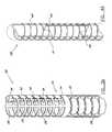
- the catheteris configured so that the distal region of the catheter body 10 deflects in more than one plane to provide a “cork-screw” or helical tip region.
- a screw shapeis shown, the catheter can be configured to provide other complex configurations.
- the cathetercan be actuated and used though a range of deflections at points other than a maximally deflected configuration. In other words, the system is not simply a two-state system (no deflection/full deflection).
- FIG. 1Aillustrates a catheter body 10 having multiple loops, wherein the distal end of the catheter is deflected well in excess of 360 degrees.
- the systemalso includes a handle 12 .
- First and second umbilicals 14 and 16can be provided to connect the handle 12 to a console (not shown) that supports the surgical function of the selected device.
- the first umbilical 14can provide a path for a liquid or gas refrigerant to be transferred between the console and the handle 12 ; and the second umbilical 16 can provide a signal path, such as for electrical signals, between the console and the handle.
- Additional umbilicalscan be provided as required, and the functions of more than one umbilical can be provided in a single, multifunction umbilical.
- one or more of the umbilicalscan be divisible into two or more portions as shown in FIG. 1B , wherein the first umbilical includes portion 14 and 14 ′.
- FIG. 2depicts an exemplary embodiment as shown in FIG. 1 b which further includes a pull-wire 18 .
- the present inventioncan use pull-wires to cause deflection, as discussed below, additional structures are provided that cause the deflection to produce a shape other than a simple, single plane bend. Further, although a pull-wire(s) can be used to cause deflection, the disclosed structures can be associated with other movement mechanisms to provide the inventive configurations.
- a catheter body 10is shown in a de-constructed view so that a deflection structure 20 can be more easily understood.
- the deflection structure 20comprises a tip 22 connected to an intermediate point 24 by a connecting structure, which forms a distal deflection group.
- the connecting structureincludes first and second flexible connecting rods 26 .
- Disposed along connecting rods 26are multiple rings 28 , each defining a plane.
- Each ring 28is aligned with a plane that is substantially perpendicular to a longitudinal axis of the connecting rods 26 when in a non-actuated state as shown in FIG. 3 A.
- Connecting rods 26can also be represented by a plurality of rod segments that connect rings 28 . Additionally, a pull-wire 18 is disposed within the deflection structure 20 . Referring now to an enlarged view in FIG. 3B , the asymmetrical rings 28 have a first half 32 and a second half 34 .
- the first half 32includes a flattened, curved portion or shaped spine section 36 .
- Tensionis applied to the pull-wire 18 , which is attached at a point 38 in the tip 22 , thereby causing the deflection structure 20 to bend toward the first half 32 of the rings 28 .
- the tensioncan be applied until a full actuation state occurs and the individual spine sections 36 contact one another as shown in FIG. 3 C.
- the deflection structure 20takes a pre-determined shape that is defined by the specific physical construction of the individually shaped spine sections 36 to define a first deflection plane.
- more shaped spine sections 36may be located proximal to the intermediate point 24 with a similar arrangement as described above, further defining a second deflection plane, which is different than the first deflection plane.
- the first and second deflection planesare aligned radially different from one another.
- FIG. 3Cshows the first deflection plane 36 ′ and the second deflection plane 36 ′′.
- FIG. 3 DAn exemplary resultant shape of the catheter body in a full actuation state is shown in FIG. 3 D. Shown are the first deflection plane 36 ′ and the second deflection plane 36 ′′.
- the above described structuremay be formed from one piece of material or from multiple pieces and then secured together by methods known in the art.
- a one piece assemblycan be manufactured using a laser machining
- the materialcan be a super-elastic spring steel, a polymer or any other suitable material.
- FIG. 4Aanother exemplary embodiment of a deflection structure for a catheter is shown and discussed in greater detail.
- a deflection structure 38having first, second and third planar shims 40 .
- Each planar shim 40is a flat elongate piece of material with ends, and that define discrete planes.
- Each of the planar shims 40are joined to one another at their ends and are aligned in a different plane relative to each other.
- each of the deflection shimswill bend in a deflection plane that is substantially perpendicular to the shim's plane and will form a pre-determined actuation shape.
- a coil 41can be disposed around at least a portion of the joined planar shims 40 .
- FIG. 4Bshows a deconstructed view of the deflection structure of FIG. 4A in an actuated state
- planar shims 40are each actuated in a separate plane. Shown is a first deflection plane 40 ′, a second deflection plane 40 ′′ and a third deflection plane 40 ′′′.
- the actuation of the deflection shims 40can be accomplished by one or more pull-wires disposed within the deflection mechanism and attached at various locations to effect different final and intermediate configurations.
- the planar shims 40can be joined in many different ways, for example, they may be slotted and fitted together or they may be welded together.
- the planar shimscan be constructed from a spring material and actuation may be accomplished by applying tension supplied by one or more pull-wires, or by constructing the planar shims from a shape-memory material and applying that materials' required means, as is known in the shape-memory art. For example, inducing a temperature change in the material can cause it to assume a preset shape.
- FIG. 5another exemplary embodiment of a deflection structure for a catheter is shown and discussed in greater detail.
- a deflection body 42Disposed within an optional helical coil 44 are a first set 46 and second set 48 of longitudinal elements arranged substantially parallel to a longitudinal axis of deflection body 42 .
- the helical coil 44helps to maintain a relatively straight configuration of the deflection structure when in a non-actuated state.
- the first set 46 and second set 48 of longitudinal elementseach define an independent plane of deflection, a first deflection plane 46 ′ and a second deflection plane 38 ′ respectively, when actuated.
- a junction 50defines the relative radial angle of alignment of the sets of longitudinal elements.
- FIG. 7 and FIG. 8show detailed views of a junction 50 that can be used to join the first and second sets of longitudinal elements at different radial angles relative to one another.
- the longitudinal elementscan be manufactured from a spring material and actuation can be accomplished by applying tension with one or more pull-wires, or by constructing the longitudinal elements from a shape-memory material and applying that materials' required means, such as temperature.
- FIG. 5shows the deflection structure 42 in a non-actuated state.
- the deflection structureWhen the deflection structure is actuated it assumes a pre-determined shape, for example, as shown in FIG. 6 .
- FIG. 9another exemplary embodiment of a deflection structure for a catheter is shown and discussed in greater detail.
- This embodimentcomprises a series of longitudinal elements 54 embedded or attached to a flexible tube 56 .
- the longitudinal elements 54are constructed of a spring material or a shape-memory material.
- tensionis applied to a pull-wire 58 or alternatively when the actuating mechanism of the shape memory material is applied, the longitudinal elements 54 deflect in different planes to assume an actuation state as shown in FIG. 14 .
- the relative radial angle of multiple sets of longitudinal elements 54can be controlled to specifically define final or intermediate actuation state shapes according to application demands.
- Transition zone 60can be seen in FIGS. 9 , 10 and 11 . Transition from one plane to another can be immediate or gradual. Further, a junction 50 as seen in FIGS. 7 and 8 can be used.
- a coiled element set 62can be used to create an uncoiling action upon actuation resulting in an actuation state as seen in FIG. 14 .
- the final actuation statecan be predetermined to suit application demands by the manufacturer.
- FIG. 13Shown in FIG. 13 , is a set helically twisted elements 64 having a continuous helical-shaped twist contained inside a deflection body 66 .
- a pull-wire 68is attached to a distal end 70 of the deflection body 66 .
- a wire coil 72encloses the assembly and supports a membrane 74 . The coil 72 prevents the pull-wire 68 from “straightening” when in a non-actuated state.
- the struts 64are deflected in a plane perpendicular to the struts, in a continuously rotating direction.
- the final shape of the distal end 70is a ring 74 configured perpendicular to the catheter shaft 76 , as seen in FIG. 14 .
- the plane in which the distal end 70 moves to the ring 74can be made to be in a plane perpendicular to the shaft, depending on the pitch and number of twists.
- FIG. 14shows a first deflection plane 74 ′ and a second deflection plane 74 ′′.
- the deflection structure 76comprises a shape biased member 78 included in a distal section of a catheter tip 80 , and a sheath 82 that houses the catheter tip 80 until the place and time of actuation.
- the shape biased member 78has a pre-determined shape and can be reversibly conformed to a non-actuated state 84 by sliding the sheath 82 over it. When the sheath 82 is partially withdrawn from the catheter tip 80 or the catheter tip 80 is advanced relative to the sheath 82 , the shape biased member 78 assumes its pre-determined shape and is thus actuated.
- the shape biased member 78may be made of polymer, a spring-tempered stainless or super-elastic alloy that when released from the sheath 82 will force the catheter tip 80 to take the shape desired.
- FIG. 15shows a first deflection plane 80 ′ and a second deflection plane 80 ′′.
- FIG. 16Another embodiment as disclosed in FIG. 16 shows a deflection structure 86 which comprises a plurality of curves 88 with a pre-established deflection shape.
- a series of beveled-faced elements 90are placed over one or more wires 92 (either rectangular section wire or a set of round wires). Initially the beveled-faced elements 90 are free-floating on the wires 92 , with small intervals 94 in between each element 90 .
- a first element 96When a pull tension is applied to the wires 92 , a first element 96 will be pressed against a fixed point 98 at the deflection structure tip 100 , and subsequently each of the remaining elements 90 will be pulled close together until all the beveled facets are in contact with one another, thereby imparting a specific angular abutment to the catheter tip in a pre-established shape.
- the pre-established shapedepends on the sequence of angles on the faces of the elements and their predetermined configuration.
- FIG. 16shows an exemplary actuation shape.
- FIG. 18Another exemplary embodiment as shown in FIG. 18 comprises a preformed balloon insert 102 placed in a distal segment 104 of a catheter tip 106 which upon inflation conforms the catheter tip to a predetermined profile 107 as seen in FIG. 19 .
- the preformed balloon insert 102acts as an insulation material.
- the preformed balloon insert 102is constructed from a non-compliant balloon that is preformed by blow-molding and/or thermally setting or by other suitable means to a defined shape.
- the preformed balloon insert 102is housed in a distal end of a catheter 10 as seen in FIG. 1 .
- the preformed balloon insert 102After being placed close to the target tissue, the preformed balloon insert 102 is inflated with a non-compressible, biocompatible liquid through an inflation lumen (not shown).
- the preformed balloon insert 102will force the catheter tip 104 to take its shape.
- the preformed balloon insert 102has a triple role, shaping the tip, increasing rigidity, and shielding the catheter's
- the systemincludes a catheter body 210 , a deflection region 212 and a distal region 214 , all having a longitudinal axis.
- the deflection region 212is shown in a resting or non-deflected state or condition.
- the cathetercan be configured to provide various pre-defined deflection shapes. Further, various distal region arrangements can be used in combination with the deflection region of the invention.
- the systemalso includes a handle 216 .
- First and second umbilicals 218 and 220can be provided to connect the handle 216 to a console (not shown) that supports the surgical function of the selected device.
- the first umbilical 218provides a path for a liquid or gas refrigerant to be transferred between the console and the handle and the second umbilical 220 provides a signal path, such as for electrical signals, between the console and the handle.
- Additional umbilicalscan be provided as required, and the functions of more than one umbilical can be provided in a single, multifunction umbilical. Also, one or more of the umbilicals can be divisible into two or more portions as shown in FIG.
- the first umbilicalincludes two portions of umbilical 218 such as for fluid infusion into the catheter and a vacuum for the excavation of the fluid.
- one or more actuator members 222can be disposed within the catheter body 210 .
- a pull wire, a tape or any other suitable structure for applying a forcecan be disposed within the catheter body 210 .
- the catheter system of FIG. 21is shown in an actuated state.
- the catheter systemtakes the actuated state when a force is applied via the actuator member 222 .
- the plane of deflection and shape of the actuated stateis dictated by the physical construction of the catheter system. More specifically, the plane of deflection and shape is dictated by the flexibility and density of the deflection region 212 and the presence and physical attributes of one or more longitudinal elements 224 adjacent or within the deflection region 212 (shown in phantom).
- the deflection region 212is defined by a deflection wall 226 which is manufactured from a formable resilient material having a specific density and flexibility rating.
- the longitudinal elements 224which are provided within or on the deflection wall 226 , in combination with the actuator member 222 and the deflection wall 226 define the plane and shape of the deflection of the deflection region 212 .
- two longitudinal elements 224are shown in phantom, however, a lesser or greater number of elements can be provided.
- the present inventionprovides a device that can dictate a predefined deflection plane and shape.
- the structure of the body 210provides for torque transfer between the handle 216 and the deflection region 212 and thereby to the distal region 214 .
- FIG. 23an alternate exemplary embodiment of a deflection structure for a catheter is shown and discussed in greater detail. Shown is a deflection region 212 and distal region 214 . Disposed within the deflection wall 226 are two sets of longitudinal elements 228 and 230 arranged substantially parallel to a longitudinal axis of deflection region 212 . The first set 228 and second set 230 of longitudinal elements each define an independent plane of deflection, a first deflection plane 232 and a second deflection plane 234 respectively, when actuated. As shown in FIG. 23 , the sets of longitudinal members can be radially aligned to define a specific defined deflection shape.
- the longitudinal elements 224provide for a bias to the non-actuated state and partially define the plane of deflection. For example, if two longitudinal elements are radially aligned 180 degrees apart and an actuation force is applied, the structure will bend in a direction perpendicular to a combined longitudinal axis of the longitudinal elements. Further, the deflection plane and shape are defined by the relative rigidity or flexibility of the deflection wall 226 . For example if a section of the wall is relatively rigid, the radius of bend at that section will be greater than that of a section having a less rigid composition.
- FIG. 23While multiple sets of longitudinal elements are shown in FIG. 23 , for the purposes of explanation, one set of longitudinal members will be described hereafter. However, it is understood that any of the alternate exemplary embodiments discussed herein can employ one or more longitudinal elements. Also shown in FIG. 23 is an optional coil 229 which can be provided in any of the embodiments discussed herein.
- the coil 229can extend the entire length of the catheter system or a some lesser portion thereof.
- the coil 229provides for torsional transfer along the catheter system, resistance to compressional forces and can bias the system to a pre-determined shape.
- any set of radially aligned longitudinal elements 224can be replaced by a flat planar shim having a length comparable to the longitudinal elements 224 , whereby the edges of the shim provide similar functionality as the individual longitudinal elements 224 .
- FIG. 24is a sectional view taken along line 24 — 24 in FIG. 21 , one embodiment of the deflection region is described in more detail.
- FIG. 24shows longitudinal elements 224 positioned within deflection wall 226 and substantially aligned with the longitudinal axis of the deflection region 212 .
- the longitudinal elements 224have a fixed rigidity that is greater then the rigidity of the deflection wall 226 .
- Located within a deflection conduit 236are actuator members 222 .
- FIG. 24shows two longitudinal elements 224 aligned radially 180 degrees from one another on the deflection wall 226 and two deflection conduits 236 radially aligned 180 degrees from one another on the deflection wall 226 .
- the longitudinal elements 224can be embedded within the deflection wall 226 during formation of the deflection wall 226 or can be attached to a portion of the wall by commonly known adhesive methods or equivalent. Alternately, the longitudinal elements 224 can be affixed to an optional coil provided within the wall 226 or adjacent thereto. Likewise, the deflection conduits 236 can be embedded in the deflection wall 226 or be attached to the wall. It is contemplated that the radial alignment of the longitudinal elements can be from substantially 0 degrees to substantially 360 degrees depending on the desired deflection plane and shape. As such an alternate exemplary embodiment provides two longitudinal elements 224 positioned on the same “side” of the deflection wall 236 as one another, or less than 180 degrees from one another.
- one or more deflection conduits 236 and longitudinal elements 224can be positioned in varying locations around deflection wall 226 .
- one or more longitudinal elements 224are arranged to define a preferred deflection shape and/or plane.
- adjusting the rigidity of the deflection wall 226affects a different radius of bend when a force is applied to the deflection region 212 .
- various materialsmay be used to construct the longitudinal elements 224 . Several examples of suitable materials are NiTi, spring steel and carbon fiber.
- a deflection lumen 238which is defined by the deflection wall 226 . The deflection lumen provides passage for both fluids and accessories between each end of the catheter system as is known in the art.
- FIG. 25is an alternate cross sectional view taken along line 24 — 24 in FIG. 21 , another embodiment is discussed in more detail.
- a rib 240having a length, is provided protruding into the deflection lumen 238 from the deflection wall 226 and extending either the length of the deflection region 212 or a lesser portion thereof.
- longitudinal elements 224are positioned within rib 240 .
- Rib 240is constructed from material that can have a varying rigidity along its length. By controlling the rigidity of the rib 240 during manufacturing, a preferred deflection shape can be defined by controlling bend radii along the length of the rib 240 .
- variable rigidityBy providing variable rigidity along the length of rib 240 , variable resistance to a bending force is provided, thereby defining bend shape and plane of deflection. It will be readily understood that an area of the rib 240 with a greater rigidity will have a greater radius of bend compared to an area with a lesser rigidity which has a lesser radius of bend per unit force that is applied by the actuator member 222 . As discussed above, one or more deflection conduits 236 and one or more longitudinal elements 224 can be provided at variable locations along the deflection wall 226 . Thus, it has advantageously been found that deflection shape and deflection plane alignment can be defined by varying the rigidity of deflection wall 226 or rib 240 while maintaining a constant rigidity of the longitudinal elements 224 .
- wall section 242is constructed to have a greater rigidity of structure when compared to the rigidity of deflection wall 226 . Further, wall section 242 can either extend the length of the deflection region or a lesser portion thereof. This arrangement allows the wall section 242 to define a bend radii in a similar manner as the longitudinal element and deflection wall configuration provided above. Further, relative rigidity along the length of wall section 242 can be varied to specifically define a preferred deflection shape and/or deflection plane.
- a deflection region where one section of the wall section 242 has a more rigid structure when compared to another section of the wall section 242will defined a greater bend radius at the greater rigidity section than the lesser rigidity section, per unit force applied by the actuator member 222 .
- one or more deflection conduits 236 and one or more actuator members 224can be provided along the deflection wall 226 .
- the wall sectionscan be referred to as ribs and have various shapes as will be apparent from the disclosure of the present invention.
- FIG. 27shows an alternate embodiment discussed in more detail, where individual sections of the deflection wall 226 have different rigidity compared to other sections of the deflection wall 226 .
- FIG. 27shows a side view of a catheter system of the invention, in a preferred deflection state.
- First wall sub-section 244has a different rigidity compared to second wall sub-section 246
- third wall sub-section 248has a different rigidity compared to second wall sub-section 246 .
- many such sectionsmay be arranged to provide areas with varying rigidity. It is contemplated that the boundary between different sections can be a smooth transition from one rigidity to another or in distinct transitions as shown here.
- the longitudinal memberhas a constant rigidity along its length (not shown).
- the manufacturercan define the preferred deflection plane and shape. This manner of defining deflection plane and shape is easier to accomplish and less expensive than prior art methods.
- the manufacturercontrols the deflection parameters. It is also contemplated that the deflection wall 226 can have a constant rigidity to define a simple deflection pattern.
- FIG. 28is an alternate sectional view of an exemplary embodiment of the body 210 of the catheter taken along line 28 — 28 in FIG. 21 .
- the body 210has a wall 250 which defines a body lumen 252 .
- the body lumen 252is configured to pass fluids to and from each end of the catheter system.
- a conduit 254Further disposed within the body lumen 252 is a conduit 254 .
- An actuator member 222is disposed within the conduit 254 having a first end and a second end, wherein the first end is connected to an actuator within the handle and the second end is connected to an attachment point within the deflection region (not shown).
- the conduit 254can either be provided in a central location as shown in FIG. 28 or along the wall 250 as shown in FIG. 29 .
- the wall 50further defines a hollow deflection conduit 256 which is configured to receive the actuator member 222 .
- the deflection conduit 256can alternatively run the entire longitudinal length of the wall 250 as shown in FIG. 29 or a portion thereof, as shown in FIG. 28 .
- the deflection conduit 256can be an integral formation of the wall 256 , or can be a separate piece which is attached along the wall 256 or some combination thereof.
- the wall 256can be constructed from any formable resilient material.
- the wall 256is constructed from a formable resilient polymer or plastic.
- FIGS. 28 and 30show exemplary embodiments where further provided within the lumen 252 is a torqueable member 258 having a first end and a second end.
- the torqueable member 258can either be located adjacent the wall 250 as shown in FIG. 28 or adjacent the centrally located conduit 254 as shown in FIG. 30 . In both cases, the torqueable member 258 is mechanically connected to the handle 216 at the first end and to a point adjacent the deflection region 212 at the second end.
- the torqueable member 258can be mechanically connected by methods known in the art, such as, for example adhesive bonding or by forming the handle around the torqueable member 258 .
- the torqueable member 258has a rigidity less than that of a steel pipe and more than that of a piece of string.
- the torqueable member 258has a structure that resists rotational twisting when a rotational force is applied to an end.
- the torqueable member 258has a structure that will transmit the rotational force along its length.
- the torqueable member 258facilitates the transmission of rotational forces from the handle 216 to the deflection region 212 .
- the torqueable member 258can be configured in many different ways, for example, it may include a helical coil, a braided sheath or other such devices.
- the torqueable member 258can be constructed from a wide variety of materials, for example, coiled or braided metals or plastics or other such materials which exhibit the characteristics discussed herein.
- FIG. 31is a sectional view taken along line 31 — 31 of FIG. 28 .
- FIG. 31shows a plurality of vanes 260 positioned between the torqueable member 258 and the conduit 254 .
- the vanes 260are provided to interconnect central components, such as the conduit 254 and the torqueable member 258 as shown in FIG. 31 , with the outer components.
- the vanes 260provide a support for and a connection between the central components and the outer components.
- the vanes 260define additional lumens 262 which can serve as passageway for fluids or additional components.
- FIG. 32which is a cross sectional view taken along line 32 — 32 of FIG.
- the vanes 260can also engage the torqueable member 258 when it is positioned adjacent the conduit 254 .
- the vanes 260can alternately extend the entire length of the body or some lesser portion thereof. It is contemplated that the vanes 260 can be created in a variety of ways, for example, by using a casting manufacturing process to create the device, formed during an extrusion process or by bonding to the wall 224 during an assembly process. Construction alternatives are discussed in further detail below.
- the wall 250can optionally contain a non-compressible element 264 .
- the non-compressible element 264can be a braided material disposed within the wall 250 .
- the non-compressible element 264is configured to maintain the shape of the body 210 under compressional loads, which can occur during use of the catheter system.
- the non-compressible element 264can alternately extend the entire length of the catheter system or some lesser portion thereof.
- the non-compressible element 264can be constructed in a variety of manners and from a variety of material.
- the non-compressible element 264can be a braided sleeve, a coiled tube or other such structures that afford the ability to resist a compression force.
- the non-compressible element 264can be constructed of metal, plastic or a combination thereof.
- the non-compressible element 264is a braided metal sleeve that is cast within the wall 250 .
- the deflection regionhas a first non-actuated state.
- tensionis applied to an actuator member 222 disposed within catheter system, a force is transmitted to the distal region which causes the deflection structure to bend toward one side.
- the tensioncan be applied until a full actuation state occurs and the preferred deflection shape is reached as shown in FIG. 22 .
- the deflection region 212takes a pre-determined shape that is defined by the specific physical construction of the longitudinal elements 224 and specific rigidity of the deflection wall. The structure of the longitudinal elements biases the deflection region to the non-actuated state.
- the deflection shape and planeare defined by the specific alignment of the longitudinal elements and the variable rigidity of the material surrounding the longitudinal elements 224 . For example, by defining the bend radii of different sections of the deflection region.
- the catheter system of the inventioncan be constructed by techniques known in the art, such as using a single tube to manufacture the catheter.
- the cathetercan be constructed by using a die or mandrel, over which the catheter is drawn or cast.
- One such methodincludes positioning all of the preformed components of the system around a central “lumen mandrel.”
- the material that makes up the walls of the catheteris cast around the preformed components.
- the preformed componentscan include the longitudinal elements, the actuator conduits, and any coils or other structural support components.
- the casting materialis then allowed to harden and the “lumen mandrel” is removed.
- the casting materialmay be “doped” to effect final rigidity of a selected portion of the walls.
- the componentscan be soldered together before casting to add strength and/or prevent movement of the components during construction.
- Additional discrete deflection structure sectionscan be added to the catheter tip to form other desired deflection shapes.
Landscapes
- Health & Medical Sciences (AREA)
- Life Sciences & Earth Sciences (AREA)
- Biophysics (AREA)
- Pulmonology (AREA)
- Engineering & Computer Science (AREA)
- Anesthesiology (AREA)
- Biomedical Technology (AREA)
- Heart & Thoracic Surgery (AREA)
- Hematology (AREA)
- Animal Behavior & Ethology (AREA)
- General Health & Medical Sciences (AREA)
- Public Health (AREA)
- Veterinary Medicine (AREA)
- Media Introduction/Drainage Providing Device (AREA)
Abstract
Description
Claims (28)
Priority Applications (8)
| Application Number | Priority Date | Filing Date | Title |
|---|---|---|---|
| US10/002,957US6890329B2 (en) | 1999-06-15 | 2001-11-01 | Defined deflection structure |
| CA002465141ACA2465141C (en) | 2001-11-01 | 2002-09-25 | Defined deflection structure |
| EP10177733AEP2289589A3 (en) | 2001-11-01 | 2002-09-25 | Defined Deflection Structure |
| EP02773592AEP1450889A4 (en) | 2001-11-01 | 2002-09-25 | Defined deflection structure |
| CA2581115ACA2581115C (en) | 2001-11-01 | 2002-09-25 | Defined deflection structure |
| EP08011930AEP1977781B1 (en) | 2001-11-01 | 2002-09-25 | Defined deflection structure |
| PCT/US2002/030527WO2003037416A1 (en) | 2001-11-01 | 2002-09-25 | Defined deflection structure |
| US11/112,100US7955298B2 (en) | 1999-06-15 | 2005-05-09 | Defined deflection structure |
Applications Claiming Priority (3)
| Application Number | Priority Date | Filing Date | Title |
|---|---|---|---|
| US13919399P | 1999-06-15 | 1999-06-15 | |
| US09/596,227US6585717B1 (en) | 1999-06-15 | 2000-06-15 | Deflection structure |
| US10/002,957US6890329B2 (en) | 1999-06-15 | 2001-11-01 | Defined deflection structure |
Related Parent Applications (1)
| Application Number | Title | Priority Date | Filing Date |
|---|---|---|---|
| US09/596,227Continuation-In-PartUS6585717B1 (en) | 1999-06-15 | 2000-06-15 | Deflection structure |
Related Child Applications (1)
| Application Number | Title | Priority Date | Filing Date |
|---|---|---|---|
| US11/112,100DivisionUS7955298B2 (en) | 1999-06-15 | 2005-05-09 | Defined deflection structure |
Publications (2)
| Publication Number | Publication Date |
|---|---|
| US20020082585A1 US20020082585A1 (en) | 2002-06-27 |
| US6890329B2true US6890329B2 (en) | 2005-05-10 |
Family
ID=21703371
Family Applications (2)
| Application Number | Title | Priority Date | Filing Date |
|---|---|---|---|
| US10/002,957Expired - Fee RelatedUS6890329B2 (en) | 1999-06-15 | 2001-11-01 | Defined deflection structure |
| US11/112,100Expired - Fee RelatedUS7955298B2 (en) | 1999-06-15 | 2005-05-09 | Defined deflection structure |
Family Applications After (1)
| Application Number | Title | Priority Date | Filing Date |
|---|---|---|---|
| US11/112,100Expired - Fee RelatedUS7955298B2 (en) | 1999-06-15 | 2005-05-09 | Defined deflection structure |
Country Status (4)
| Country | Link |
|---|---|
| US (2) | US6890329B2 (en) |
| EP (3) | EP2289589A3 (en) |
| CA (1) | CA2465141C (en) |
| WO (1) | WO2003037416A1 (en) |
Cited By (83)
| Publication number | Priority date | Publication date | Assignee | Title |
|---|---|---|---|---|
| US20050256452A1 (en)* | 2002-11-15 | 2005-11-17 | Demarchi Thomas | Steerable vascular sheath |
| US20070244413A1 (en)* | 2006-04-12 | 2007-10-18 | Medtronic Vascular, Inc. | Medical guidewire tip construction |
| US20080287741A1 (en)* | 2007-05-18 | 2008-11-20 | Boston Scientific Scimed, Inc. | Articulating torqueable hollow device |
| US20090069632A1 (en)* | 2007-09-10 | 2009-03-12 | Boston Scientific Scimed, Inc. | Medical instrument with a deflectable distal portion |
| US20090182289A1 (en)* | 2006-06-22 | 2009-07-16 | Hans List | Flexible device for introducing a medical apparatus into a body |
| US20090192495A1 (en)* | 2008-01-24 | 2009-07-30 | Boston Scientific Scimed, Inc. | Structure for use as part of a medical device |
| US20090240109A1 (en)* | 2008-03-24 | 2009-09-24 | Boston Scientific Scimed, Inc. | Flexible endoscope with core member |
| US20110098529A1 (en)* | 2009-10-28 | 2011-04-28 | Boston Scientific Scimed, Inc. | Method and Apparatus Related to a Flexible Assembly at a Distal End Portion of a Medical Device |
| US8080000B2 (en) | 2004-04-21 | 2011-12-20 | Acclarent, Inc. | Methods and apparatus for treating disorders of the ear nose and throat |
| US8088101B2 (en) | 2004-04-21 | 2012-01-03 | Acclarent, Inc. | Devices, systems and methods for treating disorders of the ear, nose and throat |
| US8100933B2 (en) | 2002-09-30 | 2012-01-24 | Acclarent, Inc. | Method for treating obstructed paranasal frontal sinuses |
| US8114113B2 (en) | 2005-09-23 | 2012-02-14 | Acclarent, Inc. | Multi-conduit balloon catheter |
| US8114062B2 (en) | 2004-04-21 | 2012-02-14 | Acclarent, Inc. | Devices and methods for delivering therapeutic substances for the treatment of sinusitis and other disorders |
| US8118757B2 (en) | 2007-04-30 | 2012-02-21 | Acclarent, Inc. | Methods and devices for ostium measurement |
| US8142422B2 (en) | 2004-04-21 | 2012-03-27 | Acclarent, Inc. | Devices, systems and methods for diagnosing and treating sinusitis and other disorders of the ears, nose and/or throat |
| US8146400B2 (en) | 2004-04-21 | 2012-04-03 | Acclarent, Inc. | Endoscopic methods and devices for transnasal procedures |
| US8172828B2 (en) | 2004-04-21 | 2012-05-08 | Acclarent, Inc. | Apparatus and methods for dilating and modifying ostia of paranasal sinuses and other intranasal or paranasal structures |
| US8182432B2 (en) | 2008-03-10 | 2012-05-22 | Acclarent, Inc. | Corewire design and construction for medical devices |
| US8190389B2 (en) | 2006-05-17 | 2012-05-29 | Acclarent, Inc. | Adapter for attaching electromagnetic image guidance components to a medical device |
| US20120158021A1 (en)* | 2010-12-19 | 2012-06-21 | Mitralign, Inc. | Steerable guide catheter having preformed curved shape |
| US8388642B2 (en) | 2005-01-18 | 2013-03-05 | Acclarent, Inc. | Implantable devices and methods for treating sinusitis and other disorders |
| US8414473B2 (en) | 2004-04-21 | 2013-04-09 | Acclarent, Inc. | Methods and apparatus for treating disorders of the ear nose and throat |
| US8435290B2 (en) | 2009-03-31 | 2013-05-07 | Acclarent, Inc. | System and method for treatment of non-ventilating middle ear by providing a gas pathway through the nasopharynx |
| US8439687B1 (en) | 2006-12-29 | 2013-05-14 | Acclarent, Inc. | Apparatus and method for simulated insertion and positioning of guidewares and other interventional devices |
| US20130165908A1 (en)* | 2011-12-02 | 2013-06-27 | Barosense, Inc. | Positioning device and articulation assembly for remote positioning of a tool |
| US8485199B2 (en) | 2007-05-08 | 2013-07-16 | Acclarent, Inc. | Methods and devices for protecting nasal turbinate during surgery |
| US8702626B1 (en) | 2004-04-21 | 2014-04-22 | Acclarent, Inc. | Guidewires for performing image guided procedures |
| US8715169B2 (en) | 2004-04-21 | 2014-05-06 | Acclarent, Inc. | Devices, systems and methods useable for treating sinusitis |
| US8740929B2 (en) | 2001-02-06 | 2014-06-03 | Acclarent, Inc. | Spacing device for releasing active substances in the paranasal sinus |
| US8747389B2 (en) | 2004-04-21 | 2014-06-10 | Acclarent, Inc. | Systems for treating disorders of the ear, nose and throat |
| US8764729B2 (en) | 2004-04-21 | 2014-07-01 | Acclarent, Inc. | Frontal sinus spacer |
| US8774913B2 (en) | 2002-04-08 | 2014-07-08 | Medtronic Ardian Luxembourg S.A.R.L. | Methods and apparatus for intravasculary-induced neuromodulation |
| US8834464B2 (en) | 1999-04-05 | 2014-09-16 | Mark T. Stewart | Ablation catheters and associated systems and methods |
| US8864787B2 (en) | 2004-04-21 | 2014-10-21 | Acclarent, Inc. | Ethmoidotomy system and implantable spacer devices having therapeutic substance delivery capability for treatment of paranasal sinusitis |
| US8888773B2 (en) | 2012-05-11 | 2014-11-18 | Medtronic Ardian Luxembourg S.A.R.L. | Multi-electrode catheter assemblies for renal neuromodulation and associated systems and methods |
| US8894614B2 (en) | 2004-04-21 | 2014-11-25 | Acclarent, Inc. | Devices, systems and methods useable for treating frontal sinusitis |
| US8934978B2 (en) | 2002-04-08 | 2015-01-13 | Medtronic Ardian Luxembourg S.A.R.L. | Methods and apparatus for renal neuromodulation |
| US8932276B1 (en) | 2004-04-21 | 2015-01-13 | Acclarent, Inc. | Shapeable guide catheters and related methods |
| US8951225B2 (en) | 2005-06-10 | 2015-02-10 | Acclarent, Inc. | Catheters with non-removable guide members useable for treatment of sinusitis |
| US8956352B2 (en) | 2010-10-25 | 2015-02-17 | Medtronic Ardian Luxembourg S.A.R.L. | Catheter apparatuses having multi-electrode arrays for renal neuromodulation and associated systems and methods |
| US8979888B2 (en) | 2008-07-30 | 2015-03-17 | Acclarent, Inc. | Paranasal ostium finder devices and methods |
| US9039657B2 (en) | 2004-08-04 | 2015-05-26 | Acclarent, Inc. | Implantable devices and methods for delivering drugs and other substances to treat sinusitis and other disorders |
| US9072626B2 (en) | 2009-03-31 | 2015-07-07 | Acclarent, Inc. | System and method for treatment of non-ventilating middle ear by providing a gas pathway through the nasopharynx |
| US9084610B2 (en) | 2010-10-21 | 2015-07-21 | Medtronic Ardian Luxembourg S.A.R.L. | Catheter apparatuses, systems, and methods for renal neuromodulation |
| US9089258B2 (en) | 2004-04-21 | 2015-07-28 | Acclarent, Inc. | Endoscopic methods and devices for transnasal procedures |
| US9095321B2 (en) | 2012-11-21 | 2015-08-04 | Medtronic Ardian Luxembourg S.A.R.L. | Cryotherapeutic devices having integral multi-helical balloons and methods of making the same |
| US9101384B2 (en) | 2004-04-21 | 2015-08-11 | Acclarent, Inc. | Devices, systems and methods for diagnosing and treating sinusitis and other disorders of the ears, Nose and/or throat |
| US9107574B2 (en) | 2004-04-21 | 2015-08-18 | Acclarent, Inc. | Endoscopic methods and devices for transnasal procedures |
| US9155492B2 (en) | 2010-09-24 | 2015-10-13 | Acclarent, Inc. | Sinus illumination lightwire device |
| US9179974B2 (en) | 2013-03-15 | 2015-11-10 | Medtronic Ardian Luxembourg S.A.R.L. | Helical push wire electrode |
| US9265407B2 (en) | 2004-04-21 | 2016-02-23 | Acclarent, Inc. | Endoscopic methods and devices for transnasal procedures |
| US9351750B2 (en) | 2004-04-21 | 2016-05-31 | Acclarent, Inc. | Devices and methods for treating maxillary sinus disease |
| US9370639B2 (en) | 2013-03-12 | 2016-06-21 | Cook Medical Technologies, LLC | Variable stiffness catheter |
| US9399121B2 (en) | 2004-04-21 | 2016-07-26 | Acclarent, Inc. | Systems and methods for transnasal dilation of passageways in the ear, nose or throat |
| US9433752B2 (en) | 2012-11-14 | 2016-09-06 | Biosense Webster (Israel) Ltd. | Catheter with flat beam deflection in tip |
| US9433437B2 (en) | 2013-03-15 | 2016-09-06 | Acclarent, Inc. | Apparatus and method for treatment of ethmoid sinusitis |
| US9468362B2 (en) | 2004-04-21 | 2016-10-18 | Acclarent, Inc. | Endoscopic methods and devices for transnasal procedures |
| US9629684B2 (en) | 2013-03-15 | 2017-04-25 | Acclarent, Inc. | Apparatus and method for treatment of ethmoid sinusitis |
| US9694161B2 (en) | 2012-11-14 | 2017-07-04 | Biosense Webster (Israel), Ltd. | Catheter with flat beam providing nonsymmetrical curve bi-directional deflection |
| US9707035B2 (en) | 2002-04-08 | 2017-07-18 | Medtronic Ardian Luxembourg S.A.R.L. | Methods for catheter-based renal neuromodulation |
| US9795765B2 (en) | 2010-04-09 | 2017-10-24 | St. Jude Medical International Holding S.À R.L. | Variable stiffness steering mechanism for catheters |
| US9820688B2 (en) | 2006-09-15 | 2017-11-21 | Acclarent, Inc. | Sinus illumination lightwire device |
| US9855404B2 (en) | 2013-05-03 | 2018-01-02 | St. Jude Medical International Holding S.À R.L. | Dual bend radii steering catheter |
| US9913573B2 (en) | 2003-04-01 | 2018-03-13 | Boston Scientific Scimed, Inc. | Endoscopic imaging system |
| US9918705B2 (en) | 2016-07-07 | 2018-03-20 | Brian Giles | Medical devices with distal control |
| US10166069B2 (en) | 2014-01-27 | 2019-01-01 | Medtronic Ardian Luxembourg S.A.R.L. | Neuromodulation catheters having jacketed neuromodulation elements and related devices, systems, and methods |
| US10188829B2 (en) | 2012-10-22 | 2019-01-29 | Medtronic Ardian Luxembourg S.A.R.L. | Catheters with enhanced flexibility and associated devices, systems, and methods |
| US10188413B1 (en) | 2004-04-21 | 2019-01-29 | Acclarent, Inc. | Deflectable guide catheters and related methods |
| US10206821B2 (en) | 2007-12-20 | 2019-02-19 | Acclarent, Inc. | Eustachian tube dilation balloon with ventilation path |
| US10391274B2 (en) | 2016-07-07 | 2019-08-27 | Brian Giles | Medical device with distal torque control |
| US10441746B2 (en)* | 2015-09-04 | 2019-10-15 | Petrus A. Besselink | Flexible and steerable device |
| US10524814B2 (en) | 2009-03-20 | 2020-01-07 | Acclarent, Inc. | Guide system with suction |
| US10548663B2 (en) | 2013-05-18 | 2020-02-04 | Medtronic Ardian Luxembourg S.A.R.L. | Neuromodulation catheters with shafts for enhanced flexibility and control and associated devices, systems, and methods |
| US10736690B2 (en) | 2014-04-24 | 2020-08-11 | Medtronic Ardian Luxembourg S.A.R.L. | Neuromodulation catheters and associated systems and methods |
| US11033714B2 (en) | 2017-12-15 | 2021-06-15 | Biosense Webster (Israel) Ltd. | Catheter with biased and discrete deflection characteristics and related methods |
| US11065061B2 (en) | 2004-04-21 | 2021-07-20 | Acclarent, Inc. | Systems and methods for performing image guided procedures within the ear, nose, throat and paranasal sinuses |
| US11213678B2 (en) | 2013-09-09 | 2022-01-04 | Medtronic Ardian Luxembourg S.A.R.L. | Method of manufacturing a medical device for neuromodulation |
| US11260205B2 (en)* | 2016-08-17 | 2022-03-01 | Terumo Kabushiki Kaisha | Guide wire |
| US11471650B2 (en) | 2019-09-20 | 2022-10-18 | Biosense Webster (Israel) Ltd. | Mechanism for manipulating a puller wire |
| US11529502B2 (en) | 2004-04-21 | 2022-12-20 | Acclarent, Inc. | Apparatus and methods for dilating and modifying ostia of paranasal sinuses and other intranasal or paranasal structures |
| US20230020466A1 (en)* | 2020-04-27 | 2023-01-19 | Kardium Inc. | Medical system including steerable catheter |
| US11672947B2 (en) | 2017-11-28 | 2023-06-13 | St. Jude Medical, Cardiology Division, Inc. | Lumen management catheter |
| WO2023232924A1 (en)* | 2022-06-03 | 2023-12-07 | ETH Zürich | Steerable device for use inside of a mammalian body |
Families Citing this family (196)
| Publication number | Priority date | Publication date | Assignee | Title |
|---|---|---|---|---|
| US6719752B2 (en)* | 2000-08-31 | 2004-04-13 | Pentax Corporation | Endoscopic treatment instrument |
| US6716207B2 (en)* | 2001-05-22 | 2004-04-06 | Scimed Life Systems, Inc. | Torqueable and deflectable medical device shaft |
| US20030114832A1 (en)* | 2001-12-14 | 2003-06-19 | Kohler Robert Edward | Interventional catheter with three dimensional articulation |
| US8150519B2 (en) | 2002-04-08 | 2012-04-03 | Ardian, Inc. | Methods and apparatus for bilateral renal neuromodulation |
| US8956280B2 (en) | 2002-05-30 | 2015-02-17 | Intuitive Surgical Operations, Inc. | Apparatus and methods for placing leads using direct visualization |
| CA2499389A1 (en)* | 2002-09-18 | 2004-04-01 | The Board Of Trustees Of The Leland Stanford Junior University | Tubular compliant mechanisms for ultrasonic imaging systems and intravascular interventional devices |
| US20050165366A1 (en)* | 2004-01-28 | 2005-07-28 | Brustad John R. | Medical tubing having variable characteristics and method of making same |
| WO2005105191A2 (en)* | 2003-10-27 | 2005-11-10 | Besselink, Petrus, A. | Self-activating endoluminal device |
| US20050159728A1 (en)* | 2004-01-15 | 2005-07-21 | Thomas Medical Products, Inc. | Steerable sheath |
| US8257311B2 (en)* | 2004-04-23 | 2012-09-04 | Leonard Edward Forrest | Method and device for treatment of the spine |
| US8292931B2 (en)* | 2004-04-23 | 2012-10-23 | Leonard Edward Forrest | Method and device for placing materials in the spine |
| WO2005102433A2 (en)* | 2004-04-23 | 2005-11-03 | Leonard Edward Forrest | Device for treatment or evacuation of intervertebral disc |
| US7771411B2 (en) | 2004-09-24 | 2010-08-10 | Syntheon, Llc | Methods for operating a selective stiffening catheter |
| US7875049B2 (en) | 2004-10-04 | 2011-01-25 | Medtronic, Inc. | Expandable guide sheath with steerable backbone and methods for making and using them |
| US8382786B2 (en)* | 2004-10-27 | 2013-02-26 | Petrus A. Besselink | Self-activating endoluminal device |
| US20060116697A1 (en)* | 2004-11-30 | 2006-06-01 | Esophyx, Inc. | Flexible transoral endoscopic gastroesophageal flap valve restoration device and method |
| DE102005003632A1 (en)* | 2005-01-20 | 2006-08-17 | Fraunhofer-Gesellschaft zur Förderung der angewandten Forschung e.V. | Catheter for the transvascular implantation of heart valve prostheses |
| US11478152B2 (en) | 2005-02-02 | 2022-10-25 | Intuitive Surgical Operations, Inc. | Electrophysiology mapping and visualization system |
| US10064540B2 (en) | 2005-02-02 | 2018-09-04 | Intuitive Surgical Operations, Inc. | Visualization apparatus for transseptal access |
| US7860555B2 (en) | 2005-02-02 | 2010-12-28 | Voyage Medical, Inc. | Tissue visualization and manipulation system |
| US8137333B2 (en) | 2005-10-25 | 2012-03-20 | Voyage Medical, Inc. | Delivery of biological compounds to ischemic and/or infarcted tissue |
| US8078266B2 (en) | 2005-10-25 | 2011-12-13 | Voyage Medical, Inc. | Flow reduction hood systems |
| US9510732B2 (en) | 2005-10-25 | 2016-12-06 | Intuitive Surgical Operations, Inc. | Methods and apparatus for efficient purging |
| US20080015569A1 (en) | 2005-02-02 | 2008-01-17 | Voyage Medical, Inc. | Methods and apparatus for treatment of atrial fibrillation |
| US20070016130A1 (en)* | 2005-05-06 | 2007-01-18 | Leeflang Stephen A | Complex Shaped Steerable Catheters and Methods for Making and Using Them |
| US7988735B2 (en)* | 2005-06-15 | 2011-08-02 | Matthew Yurek | Mechanical apparatus and method for delivering materials into the inter-vertebral body space for nucleus replacement |
| CN101203265A (en)* | 2005-06-20 | 2008-06-18 | 导管治疗有限公司 | Sleeve steering and reinforcement |
| JP2009502218A (en)* | 2005-07-13 | 2009-01-29 | ザ・ボード・オブ・トラスティーズ・オブ・ザ・レランド・スタンフォード・ジュニア・ユニバーシティ | Deformable tubular shape memory alloy actuator |
| US8221310B2 (en) | 2005-10-25 | 2012-07-17 | Voyage Medical, Inc. | Tissue visualization device and method variations |
| EP1951354A4 (en)* | 2005-11-08 | 2010-09-29 | Custom Med Applications Inc | Reinforced catheter with articulated distal tip |
| US9155451B2 (en)* | 2006-03-02 | 2015-10-13 | Syntheon, Llc | Variably flexible insertion device and method for variably flexing an insertion device |
| US10123683B2 (en) | 2006-03-02 | 2018-11-13 | Syntheon, Llc | Variably flexible insertion device and method for variably flexing an insertion device |
| US9814372B2 (en) | 2007-06-27 | 2017-11-14 | Syntheon, Llc | Torque-transmitting, variably-flexible, locking insertion device and method for operating the insertion device |
| US8092374B2 (en)* | 2006-03-02 | 2012-01-10 | Kevin Smith | Variably flexible insertion device and method for variably flexing an insertion device |
| US9055906B2 (en) | 2006-06-14 | 2015-06-16 | Intuitive Surgical Operations, Inc. | In-vivo visualization systems |
| US20080097476A1 (en) | 2006-09-01 | 2008-04-24 | Voyage Medical, Inc. | Precision control systems for tissue visualization and manipulation assemblies |
| US10004388B2 (en) | 2006-09-01 | 2018-06-26 | Intuitive Surgical Operations, Inc. | Coronary sinus cannulation |
| WO2008028149A2 (en) | 2006-09-01 | 2008-03-06 | Voyage Medical, Inc. | Electrophysiology mapping and visualization system |
| US20080072903A1 (en)* | 2006-09-21 | 2008-03-27 | Gary Roth | High flow respirator circuit |
| CN101622027A (en)* | 2006-11-28 | 2010-01-06 | 导管治疗有限公司 | Catheter steering/insertion mechanism |
| US9226648B2 (en) | 2006-12-21 | 2016-01-05 | Intuitive Surgical Operations, Inc. | Off-axis visualization systems |
| US7655004B2 (en) | 2007-02-15 | 2010-02-02 | Ethicon Endo-Surgery, Inc. | Electroporation ablation apparatus, system, and method |
| US20080228135A1 (en)* | 2007-03-05 | 2008-09-18 | Elizabeth Ann Snoderly | Apparatus for treating a damaged spinal disc |
| US20100152663A1 (en)* | 2007-04-05 | 2010-06-17 | Darr Allan J | Stylet for bilumenal flexible medical device |
| US7704234B2 (en)* | 2007-04-05 | 2010-04-27 | Darr Allan J | Dynaflex |
| US8075572B2 (en) | 2007-04-26 | 2011-12-13 | Ethicon Endo-Surgery, Inc. | Surgical suturing apparatus |
| US8100922B2 (en) | 2007-04-27 | 2012-01-24 | Ethicon Endo-Surgery, Inc. | Curved needle suturing tool |
| US8657805B2 (en) | 2007-05-08 | 2014-02-25 | Intuitive Surgical Operations, Inc. | Complex shape steerable tissue visualization and manipulation catheter |
| US8262655B2 (en) | 2007-11-21 | 2012-09-11 | Ethicon Endo-Surgery, Inc. | Bipolar forceps |
| US8568410B2 (en) | 2007-08-31 | 2013-10-29 | Ethicon Endo-Surgery, Inc. | Electrical ablation surgical instruments |
| US8579897B2 (en) | 2007-11-21 | 2013-11-12 | Ethicon Endo-Surgery, Inc. | Bipolar forceps |
| US20090112059A1 (en) | 2007-10-31 | 2009-04-30 | Nobis Rudolph H | Apparatus and methods for closing a gastrotomy |
| US8480657B2 (en) | 2007-10-31 | 2013-07-09 | Ethicon Endo-Surgery, Inc. | Detachable distal overtube section and methods for forming a sealable opening in the wall of an organ |
| US9510885B2 (en) | 2007-11-16 | 2016-12-06 | Osseon Llc | Steerable and curvable cavity creation system |
| US20090131867A1 (en) | 2007-11-16 | 2009-05-21 | Liu Y King | Steerable vertebroplasty system with cavity creation element |
| US20090131886A1 (en) | 2007-11-16 | 2009-05-21 | Liu Y King | Steerable vertebroplasty system |
| CA2781407A1 (en) | 2008-01-14 | 2009-07-23 | Michael P. Brenzel | Apparatus and methods for fracture repair |
| JP5409655B2 (en) | 2008-02-05 | 2014-02-05 | スティーラブル・インスツルメンツ・ベー.フェー.ベー.アー. | Steerable tube |
| US8262680B2 (en) | 2008-03-10 | 2012-09-11 | Ethicon Endo-Surgery, Inc. | Anastomotic device |
| EP2915476B1 (en)* | 2008-03-10 | 2017-04-05 | Fortimedix Surgical B.V. | Instrument for endoscopic applications |
| US9125562B2 (en) | 2009-07-01 | 2015-09-08 | Avinger, Inc. | Catheter-based off-axis optical coherence tomography imaging system |
| US8062316B2 (en) | 2008-04-23 | 2011-11-22 | Avinger, Inc. | Catheter system and method for boring through blocked vascular passages |
| US9788790B2 (en) | 2009-05-28 | 2017-10-17 | Avinger, Inc. | Optical coherence tomography for biological imaging |
| US8696695B2 (en) | 2009-04-28 | 2014-04-15 | Avinger, Inc. | Guidewire positioning catheter |
| US8114072B2 (en) | 2008-05-30 | 2012-02-14 | Ethicon Endo-Surgery, Inc. | Electrical ablation device |
| US8679003B2 (en) | 2008-05-30 | 2014-03-25 | Ethicon Endo-Surgery, Inc. | Surgical device and endoscope including same |
| US8652150B2 (en) | 2008-05-30 | 2014-02-18 | Ethicon Endo-Surgery, Inc. | Multifunction surgical device |
| US8771260B2 (en) | 2008-05-30 | 2014-07-08 | Ethicon Endo-Surgery, Inc. | Actuating and articulating surgical device |
| US8070759B2 (en) | 2008-05-30 | 2011-12-06 | Ethicon Endo-Surgery, Inc. | Surgical fastening device |
| US8317806B2 (en) | 2008-05-30 | 2012-11-27 | Ethicon Endo-Surgery, Inc. | Endoscopic suturing tension controlling and indication devices |
| US8906035B2 (en)* | 2008-06-04 | 2014-12-09 | Ethicon Endo-Surgery, Inc. | Endoscopic drop off bag |
| US8403926B2 (en) | 2008-06-05 | 2013-03-26 | Ethicon Endo-Surgery, Inc. | Manually articulating devices |
| US20110040308A1 (en) | 2008-06-13 | 2011-02-17 | Ramiro Cabrera | Endoscopic Stitching Devices |
| US8361112B2 (en) | 2008-06-27 | 2013-01-29 | Ethicon Endo-Surgery, Inc. | Surgical suture arrangement |
| US8888792B2 (en) | 2008-07-14 | 2014-11-18 | Ethicon Endo-Surgery, Inc. | Tissue apposition clip application devices and methods |
| US8262563B2 (en)* | 2008-07-14 | 2012-09-11 | Ethicon Endo-Surgery, Inc. | Endoscopic translumenal articulatable steerable overtube |
| US8211125B2 (en) | 2008-08-15 | 2012-07-03 | Ethicon Endo-Surgery, Inc. | Sterile appliance delivery device for endoscopic procedures |
| US8529563B2 (en) | 2008-08-25 | 2013-09-10 | Ethicon Endo-Surgery, Inc. | Electrical ablation devices |
| US8241204B2 (en) | 2008-08-29 | 2012-08-14 | Ethicon Endo-Surgery, Inc. | Articulating end cap |
| US8480689B2 (en) | 2008-09-02 | 2013-07-09 | Ethicon Endo-Surgery, Inc. | Suturing device |
| US8409200B2 (en) | 2008-09-03 | 2013-04-02 | Ethicon Endo-Surgery, Inc. | Surgical grasping device |
| US8114119B2 (en) | 2008-09-09 | 2012-02-14 | Ethicon Endo-Surgery, Inc. | Surgical grasping device |
| US8118775B2 (en)* | 2008-09-09 | 2012-02-21 | Biosense Webster, Inc. | Deflectable catheter with bonded center strut and method of manufacture for same |
| AU2013203884B2 (en)* | 2008-09-09 | 2015-07-02 | Biosense Webster, Inc. | Deflectable catheter with bonded center strut and method of manufacture for same |
| US8337394B2 (en) | 2008-10-01 | 2012-12-25 | Ethicon Endo-Surgery, Inc. | Overtube with expandable tip |
| US20100121278A1 (en)* | 2008-11-13 | 2010-05-13 | David Fowler | Super elastic loop extraluminal materials delivery instrument |
| US9468364B2 (en) | 2008-11-14 | 2016-10-18 | Intuitive Surgical Operations, Inc. | Intravascular catheter with hood and image processing systems |
| US8157834B2 (en) | 2008-11-25 | 2012-04-17 | Ethicon Endo-Surgery, Inc. | Rotational coupling device for surgical instrument with flexible actuators |
| US8172772B2 (en) | 2008-12-11 | 2012-05-08 | Ethicon Endo-Surgery, Inc. | Specimen retrieval device |
| US8652129B2 (en) | 2008-12-31 | 2014-02-18 | Medtronic Ardian Luxembourg S.A.R.L. | Apparatus, systems, and methods for achieving intravascular, thermally-induced renal neuromodulation |
| US8828031B2 (en) | 2009-01-12 | 2014-09-09 | Ethicon Endo-Surgery, Inc. | Apparatus for forming an anastomosis |
| US8361066B2 (en) | 2009-01-12 | 2013-01-29 | Ethicon Endo-Surgery, Inc. | Electrical ablation devices |
| US8252057B2 (en) | 2009-01-30 | 2012-08-28 | Ethicon Endo-Surgery, Inc. | Surgical access device |
| US9226772B2 (en) | 2009-01-30 | 2016-01-05 | Ethicon Endo-Surgery, Inc. | Surgical device |
| WO2010096347A1 (en)* | 2009-02-20 | 2010-08-26 | Boston Scientific Scimed, Inc. | Asymmetric dual directional steerable catheter sheath |
| US20100298832A1 (en) | 2009-05-20 | 2010-11-25 | Osseon Therapeutics, Inc. | Steerable curvable vertebroplasty drill |
| US9039676B2 (en)* | 2009-06-11 | 2015-05-26 | St. Jude Medical Puerto Rico Llc | Apparatus and methods for catheter steerability |
| US8920369B2 (en) | 2009-06-24 | 2014-12-30 | Shifamed Holdings, Llc | Steerable delivery sheaths |
| WO2011003006A2 (en) | 2009-07-01 | 2011-01-06 | Avinger, Inc. | Atherectomy catheter with laterally-displaceable tip |
| US20110098704A1 (en) | 2009-10-28 | 2011-04-28 | Ethicon Endo-Surgery, Inc. | Electrical ablation devices |
| US8608652B2 (en) | 2009-11-05 | 2013-12-17 | Ethicon Endo-Surgery, Inc. | Vaginal entry surgical devices, kit, system, and method |
| US8376991B2 (en)* | 2009-11-09 | 2013-02-19 | St. Jude Medical, Atrial Fibrillation Division, Inc. | Device for reducing axial shortening of catheter or sheath due to repeated deflection |
| US8496574B2 (en) | 2009-12-17 | 2013-07-30 | Ethicon Endo-Surgery, Inc. | Selectively positionable camera for surgical guide tube assembly |
| US8353487B2 (en) | 2009-12-17 | 2013-01-15 | Ethicon Endo-Surgery, Inc. | User interface support devices for endoscopic surgical instruments |
| US8506564B2 (en) | 2009-12-18 | 2013-08-13 | Ethicon Endo-Surgery, Inc. | Surgical instrument comprising an electrode |
| US9028483B2 (en) | 2009-12-18 | 2015-05-12 | Ethicon Endo-Surgery, Inc. | Surgical instrument comprising an electrode |
| US20110178520A1 (en)* | 2010-01-15 | 2011-07-21 | Kyle Taylor | Rotary-rigid orthopaedic rod |
| WO2011091052A1 (en) | 2010-01-20 | 2011-07-28 | Kyle Taylor | Apparatus and methods for bone access and cavity preparation |
| US9005198B2 (en) | 2010-01-29 | 2015-04-14 | Ethicon Endo-Surgery, Inc. | Surgical instrument comprising an electrode |
| WO2011112615A1 (en) | 2010-03-08 | 2011-09-15 | Krinke Todd A | Apparatus and methods for securing a bone implant |
| US8870863B2 (en) | 2010-04-26 | 2014-10-28 | Medtronic Ardian Luxembourg S.A.R.L. | Catheter apparatuses, systems, and methods for renal neuromodulation |
| US9125671B2 (en) | 2010-04-29 | 2015-09-08 | Dfine, Inc. | System for use in treatment of vertebral fractures |
| US11382653B2 (en) | 2010-07-01 | 2022-07-12 | Avinger, Inc. | Atherectomy catheter |
| CN102058931B (en)* | 2010-12-08 | 2012-11-07 | 上海交通大学医学院附属新华医院 | Adsorbable actively bent interventional catheter driven by flexible cable |
| US20120179097A1 (en)* | 2011-01-06 | 2012-07-12 | Cully Edward H | Methods and apparatus for an adjustable stiffness catheter |
| US10092291B2 (en) | 2011-01-25 | 2018-10-09 | Ethicon Endo-Surgery, Inc. | Surgical instrument with selectively rigidizable features |
| US9314620B2 (en) | 2011-02-28 | 2016-04-19 | Ethicon Endo-Surgery, Inc. | Electrical ablation devices and methods |
| US9233241B2 (en) | 2011-02-28 | 2016-01-12 | Ethicon Endo-Surgery, Inc. | Electrical ablation devices and methods |
| US9254169B2 (en) | 2011-02-28 | 2016-02-09 | Ethicon Endo-Surgery, Inc. | Electrical ablation devices and methods |
| ES2807348T3 (en)* | 2011-03-07 | 2021-02-22 | Stryker Corp | Balloon catheter and support shaft for it |
| GB2518340A (en)* | 2011-03-15 | 2015-03-25 | Barts & London Nhs Trust | Steerable element for use in surgery |
| US9049987B2 (en) | 2011-03-17 | 2015-06-09 | Ethicon Endo-Surgery, Inc. | Hand held surgical device for manipulating an internal magnet assembly within a patient |
| EP2691038B1 (en) | 2011-03-28 | 2016-07-20 | Avinger, Inc. | Occlusion-crossing devices, imaging, and atherectomy devices |
| US9949754B2 (en) | 2011-03-28 | 2018-04-24 | Avinger, Inc. | Occlusion-crossing devices |
| US20150094656A1 (en)* | 2011-05-03 | 2015-04-02 | Amr Salahieh | Steerable medical devices, systems, and methods of use |
| US8758326B2 (en)* | 2011-06-03 | 2014-06-24 | Cook Medical Technologies Llc | Embedded wire extrusion with continuous loop tip |
| US8486009B2 (en)* | 2011-06-20 | 2013-07-16 | Hue-Teh Shih | Systems and methods for steering catheters |
| JP2014521447A (en) | 2011-07-28 | 2014-08-28 | ファスコメット ゲーエムベーハー | Steerable catheters and methods for making them |
| US9345406B2 (en) | 2011-11-11 | 2016-05-24 | Avinger, Inc. | Occlusion-crossing devices, atherectomy devices, and imaging |
| US8986199B2 (en) | 2012-02-17 | 2015-03-24 | Ethicon Endo-Surgery, Inc. | Apparatus and methods for cleaning the lens of an endoscope |
| EP2816966B1 (en)* | 2012-02-22 | 2023-10-25 | Veran Medical Technologies, Inc. | Steerable surgical catheter comprising a biopsy device at the distal end portion thereof |
| US8702647B2 (en) | 2012-04-19 | 2014-04-22 | Medtronic Ablation Frontiers Llc | Catheter deflection anchor |
| EP2849660B1 (en) | 2012-05-14 | 2021-08-25 | Avinger, Inc. | Atherectomy catheter drive assemblies |
| US9427255B2 (en) | 2012-05-14 | 2016-08-30 | Ethicon Endo-Surgery, Inc. | Apparatus for introducing a steerable camera assembly into a patient |
| WO2013172970A1 (en) | 2012-05-14 | 2013-11-21 | Avinger, Inc. | Atherectomy catheters with imaging |
| US9557156B2 (en) | 2012-05-14 | 2017-01-31 | Avinger, Inc. | Optical coherence tomography with graded index fiber for biological imaging |
| US9078662B2 (en) | 2012-07-03 | 2015-07-14 | Ethicon Endo-Surgery, Inc. | Endoscopic cap electrode and method for using the same |
| US9545290B2 (en) | 2012-07-30 | 2017-01-17 | Ethicon Endo-Surgery, Inc. | Needle probe guide |
| US9572623B2 (en) | 2012-08-02 | 2017-02-21 | Ethicon Endo-Surgery, Inc. | Reusable electrode and disposable sheath |
| US10314649B2 (en) | 2012-08-02 | 2019-06-11 | Ethicon Endo-Surgery, Inc. | Flexible expandable electrode and method of intraluminal delivery of pulsed power |
| US9277957B2 (en) | 2012-08-15 | 2016-03-08 | Ethicon Endo-Surgery, Inc. | Electrosurgical devices and methods |
| US11284916B2 (en) | 2012-09-06 | 2022-03-29 | Avinger, Inc. | Atherectomy catheters and occlusion crossing devices |
| US10029073B2 (en) | 2012-11-13 | 2018-07-24 | Abbott Cardiovascular Systems, Inc. | Steerable assembly for surgical catheter |
| US8747352B1 (en) | 2013-01-23 | 2014-06-10 | Medtronic Cryocath Lp | Balloon deflection |
| US10098527B2 (en) | 2013-02-27 | 2018-10-16 | Ethidcon Endo-Surgery, Inc. | System for performing a minimally invasive surgical procedure |
| US11096717B2 (en) | 2013-03-15 | 2021-08-24 | Avinger, Inc. | Tissue collection device for catheter |
| CN105228514B (en) | 2013-03-15 | 2019-01-22 | 阿维格公司 | Optical Pressure Sensor Assembly |
| WO2014143064A1 (en) | 2013-03-15 | 2014-09-18 | Avinger, Inc. | Chronic total occlusion crossing devices with imaging |
| EP3019096B1 (en) | 2013-07-08 | 2023-07-05 | Avinger, Inc. | System for identification of elastic lamina to guide interventional therapy |
| EP3077035B1 (en)* | 2013-12-06 | 2022-11-02 | Kalila Medical, Inc. | Steerable medical devices |
| CN105939677A (en) | 2013-12-12 | 2016-09-14 | 康文图斯整形外科公司 | Tissue displacement tools and methods |
| JP6234332B2 (en)* | 2014-06-25 | 2017-11-22 | オリンパス株式会社 | Endoscope apparatus, operation method, and operation program |
| US10357277B2 (en) | 2014-07-08 | 2019-07-23 | Avinger, Inc. | High speed chronic total occlusion crossing devices |
| US9839766B2 (en)* | 2014-10-20 | 2017-12-12 | Medtronic Cryocath Lp | Centering coiled guide |
| WO2016138443A2 (en) | 2015-02-26 | 2016-09-01 | Stryker Corporation | Surgical instrument with articulation region |
| US10420537B2 (en) | 2015-03-27 | 2019-09-24 | Shifamed Holdings, Llc | Steerable medical devices, systems, and methods of use |
| JP6820864B2 (en) | 2015-04-24 | 2021-01-27 | カリラ メディカル インコーポレイテッド | Manipulable medical devices, systems and usage |
| US10568520B2 (en) | 2015-07-13 | 2020-02-25 | Avinger, Inc. | Micro-molded anamorphic reflector lens for image guided therapeutic/diagnostic catheters |
| CN108366715A (en) | 2015-11-09 | 2018-08-03 | 施菲姆德控股有限责任公司 | Steering assembly and application method for medical treatment device |
| JP6927986B2 (en) | 2016-01-25 | 2021-09-01 | アビンガー・インコーポレイテッドAvinger, Inc. | OCT imaging catheter with delay compensation |
| EP3435892B1 (en) | 2016-04-01 | 2024-04-03 | Avinger, Inc. | Atherectomy catheter with serrated cutter |
| US11344327B2 (en) | 2016-06-03 | 2022-05-31 | Avinger, Inc. | Catheter device with detachable distal end |
| WO2018006041A1 (en)* | 2016-06-30 | 2018-01-04 | Avinger, Inc. | Atherectomy catheter with shapeable distal tip |
| US10716916B2 (en)* | 2016-07-21 | 2020-07-21 | Creganna Unlimited Company | High load steerable shaft and method for cardiac catheter |
| CN109789292B (en)* | 2016-10-05 | 2022-11-01 | 祥丰医疗私人有限公司 | Modular vascular catheter |
| EP3528864B1 (en)* | 2016-10-20 | 2020-12-30 | Heartware, Inc. | Inflow cannula |
| JP2019534130A (en) | 2016-10-27 | 2019-11-28 | ディーファイン,インコーポレイティド | Articulated osteotome with cement delivery channel |
| CA3041114A1 (en) | 2016-11-28 | 2018-05-31 | Dfine, Inc. | Tumor ablation devices and related methods |
| US10470781B2 (en) | 2016-12-09 | 2019-11-12 | Dfine, Inc. | Medical devices for treating hard tissues and related methods |
| PT3554424T (en)* | 2016-12-16 | 2023-04-03 | Edwards Lifesciences Corp | Deployment systems, tools, and methods for delivering an anchoring device for a prosthetic valve |
| US10660656B2 (en) | 2017-01-06 | 2020-05-26 | Dfine, Inc. | Osteotome with a distal portion for simultaneous advancement and articulation |
| US10675439B2 (en) | 2017-02-21 | 2020-06-09 | Abbott Cardiovascular Systems Inc. | High torsion delivery catheter element |
| US10751507B2 (en) | 2017-04-10 | 2020-08-25 | Syn Variflex, Llc | Thermally controlled variable-flexibility catheters and methods of manufacturing same |
| US11376401B2 (en) | 2017-04-26 | 2022-07-05 | Acclarent, Inc. | Deflectable guide for medical instrument |
| NL2019175B1 (en) | 2017-07-04 | 2019-01-14 | Fortimedix Surgical B V | Steerable instrument comprising a radial spacers between coaxial cylindrical elements |
| WO2019010252A2 (en) | 2017-07-04 | 2019-01-10 | Conventus Orthopaedics, Inc. | APPARATUS AND METHODS FOR TREATING BONES |
| US12167867B2 (en) | 2018-04-19 | 2024-12-17 | Avinger, Inc. | Occlusion-crossing devices |
| DE102018208539A1 (en) | 2018-05-30 | 2019-12-05 | Kardion Gmbh | A motor housing module for sealing an engine compartment of a motor of a cardiac assist system and cardiac assistance system and method for mounting a cardiac assist system |
| DE102018208933A1 (en) | 2018-06-06 | 2019-12-12 | Kardion Gmbh | A method of determining a flow rate of fluid flowing through an implanted vascular support system |
| DE102018208899A1 (en) | 2018-06-06 | 2019-12-12 | Kardion Gmbh | A method for determining the speed of sound in a fluid in the region of an implanted vascular support system |
| DE102018208913A1 (en) | 2018-06-06 | 2019-12-12 | Kardion Gmbh | A method of operating an implanted ventricular assist device |
| DE102018208879A1 (en) | 2018-06-06 | 2020-01-30 | Kardion Gmbh | Method for determining a total fluid volume flow in the area of an implanted, vascular support system |
| DE102018208862A1 (en) | 2018-06-06 | 2019-12-12 | Kardion Gmbh | Implantable vascular support system |
| DE102018210058A1 (en) | 2018-06-21 | 2019-12-24 | Kardion Gmbh | Stator blade device for guiding the flow of a fluid flowing out of an outlet opening of a heart support system, heart support system with stator blade device, method for operating a stator blade device and manufacturing method |
| US20200054198A1 (en)* | 2018-08-17 | 2020-02-20 | Ching-Shun Tseng | Endoscope With Inspection Accessory and Inspection Accessory for the Same |
| US10624762B2 (en) | 2018-09-07 | 2020-04-21 | Orthorebirth Usa | Bone graft delivery device for minimally invasive surgery |
| US11937864B2 (en) | 2018-11-08 | 2024-03-26 | Dfine, Inc. | Ablation systems with parameter-based modulation and related devices and methods |
| US11534303B2 (en) | 2020-04-09 | 2022-12-27 | Evalve, Inc. | Devices and systems for accessing and repairing a heart valve |
| US11986229B2 (en) | 2019-09-18 | 2024-05-21 | Merit Medical Systems, Inc. | Osteotome with inflatable portion and multiwire articulation |
| CN114746033B (en) | 2019-10-18 | 2025-01-10 | 阿维格公司 | Blocking crossing device |
| CN113747934B (en)* | 2020-03-10 | 2024-07-09 | 因普瑞缇夫护理公司 | Enhanced flexibility neurovascular catheter |
| JP7501011B2 (en)* | 2020-03-16 | 2024-06-18 | 住友ベークライト株式会社 | Medical indwelling device transport device and medical indwelling device transport device with indwelling device |
| US20220016394A1 (en)* | 2020-07-16 | 2022-01-20 | Canon U.S.A., Inc. | Medical Apparatus and Method of Use Thereof |
| US12311125B2 (en) | 2020-08-05 | 2025-05-27 | Medtronic, Inc. | Medical devices with multi-plane articulation |
| US20230148846A1 (en)* | 2021-11-17 | 2023-05-18 | Greene Group Industries, Llc | Single Piece Stamped Flexure |
| WO2024102411A1 (en) | 2022-11-09 | 2024-05-16 | Jenavalve Technology, Inc. | Catheter system for sequential deployment of an expandable implant |
Citations (14)
| Publication number | Priority date | Publication date | Assignee | Title |
|---|---|---|---|---|
| US4738659A (en)* | 1986-05-19 | 1988-04-19 | Sleiman Raymond A | Catheter and its method of use with a cystoscopic lens |
| US5358479A (en) | 1993-12-06 | 1994-10-25 | Electro-Catheter Corporation | Multiform twistable tip deflectable catheter |
| US5656029A (en)* | 1992-12-01 | 1997-08-12 | Cardiac Pathways Corporation | Steerable catheter with adjustable bend location and/or radius and method |
| US5807354A (en)* | 1994-06-03 | 1998-09-15 | Kenda; Rajko | An implantable catheter having intermediate length section of greater flexibility than remaining lengths |
| US5820591A (en)* | 1990-02-02 | 1998-10-13 | E. P. Technologies, Inc. | Assemblies for creating compound curves in distal catheter regions |
| US5882329A (en)* | 1997-02-12 | 1999-03-16 | Prolifix Medical, Inc. | Apparatus and method for removing stenotic material from stents |
| US6033394A (en)* | 1997-12-05 | 2000-03-07 | Intratherapeutics, Inc. | Catheter support structure |
| US6045530A (en)* | 1998-10-14 | 2000-04-04 | Heyer-Schulte Neurocare Inc. | Adjustable angle catheter |
| US6071274A (en) | 1996-12-19 | 2000-06-06 | Ep Technologies, Inc. | Loop structures for supporting multiple electrode elements |
| US6071263A (en) | 1992-03-02 | 2000-06-06 | Kirkman; Thomas R. | Apparatus and method for retaining a catheter in a blood vessel in a fixed position |
| US6074361A (en) | 1995-04-20 | 2000-06-13 | Jacobs; Clemens Josephus | Catheter |
| US6096036A (en) | 1998-05-05 | 2000-08-01 | Cardiac Pacemakers, Inc. | Steerable catheter with preformed distal shape and method for use |
| WO2001019269A1 (en) | 1999-09-15 | 2001-03-22 | The General Hospital Corporation D.B.A Massachusetts General Hospital | Pulmonary vein ablation stent and method |
| US6402719B1 (en)* | 1997-09-05 | 2002-06-11 | Cordis Webster, Inc. | Steerable DMR catheter with infusion tube |
Family Cites Families (18)
| Publication number | Priority date | Publication date | Assignee | Title |
|---|---|---|---|---|
| US2472485A (en)* | 1944-05-05 | 1949-06-07 | American Catheter Corp | Catheter-type instrument |
| US3416531A (en)* | 1964-01-02 | 1968-12-17 | Edwards Miles Lowell | Catheter |
| US4686963A (en)* | 1986-03-05 | 1987-08-18 | Circon Corporation | Torsion resistant vertebrated probe of simple construction |
| WO1989002762A1 (en)* | 1987-10-02 | 1989-04-06 | Terumo Kabushiki Kaisha | Catheter |
| US5273535A (en)* | 1991-11-08 | 1993-12-28 | Ep Technologies, Inc. | Catheter with electrode tip having asymmetric left and right curve configurations |
| ATE123957T1 (en) | 1990-12-07 | 1995-07-15 | Ruesch Willy Ag | MEDICAL INSTRUMENT WITH DIRECTORABLE TIP. |
| US5329923A (en) | 1991-02-15 | 1994-07-19 | Lundquist Ingemar H | Torquable catheter |
| WO1992015356A1 (en)* | 1991-03-01 | 1992-09-17 | Baxter International Inc. | Cardiovascular catheter having discrete regions of varying flexibility |
| DE4222271C2 (en)* | 1992-07-07 | 1996-03-28 | Wolf Gmbh Richard | Instrument for examining and / or treating the inside of the body |
| US5275152A (en)* | 1992-07-27 | 1994-01-04 | Welch Allyn, Inc. | Insertion tube terminator |
| US5364352A (en)* | 1993-03-12 | 1994-11-15 | Heart Rhythm Technologies, Inc. | Catheter for electrophysiological procedures |
| FR2713492B1 (en)* | 1993-12-09 | 1996-02-16 | Microfil Ind Sa | Adjustable tubular guide, in particular for a medical and surgical device. |
| US5571085A (en) | 1995-03-24 | 1996-11-05 | Electro-Catheter Corporation | Steerable open lumen catheter |
| US5782828A (en)* | 1996-12-11 | 1998-07-21 | Irvine Biomedical, Inc. | Ablation catheter with multiple flexible curves |
| JPH11221229A (en)* | 1997-09-24 | 1999-08-17 | Eclipse Surgical Technol Inc | Catheter |
| US6198974B1 (en)* | 1998-08-14 | 2001-03-06 | Cordis Webster, Inc. | Bi-directional steerable catheter |
| WO2000076570A2 (en)* | 1999-06-15 | 2000-12-21 | Cryocath Technologies, Inc. | Steerable catheter |
| US6450948B1 (en) | 1999-11-02 | 2002-09-17 | Vista Medical Technologies, Inc. | Deflecting tip for surgical cannula |
- 2001
- 2001-11-01USUS10/002,957patent/US6890329B2/ennot_activeExpired - Fee Related
- 2002
- 2002-09-25EPEP10177733Apatent/EP2289589A3/ennot_activeWithdrawn
- 2002-09-25EPEP02773592Apatent/EP1450889A4/ennot_activeWithdrawn
- 2002-09-25EPEP08011930Apatent/EP1977781B1/ennot_activeExpired - Lifetime
- 2002-09-25WOPCT/US2002/030527patent/WO2003037416A1/ennot_activeApplication Discontinuation
- 2002-09-25CACA002465141Apatent/CA2465141C/ennot_activeExpired - Fee Related
- 2005
- 2005-05-09USUS11/112,100patent/US7955298B2/ennot_activeExpired - Fee Related
Patent Citations (15)
| Publication number | Priority date | Publication date | Assignee | Title |
|---|---|---|---|---|
| US4738659A (en)* | 1986-05-19 | 1988-04-19 | Sleiman Raymond A | Catheter and its method of use with a cystoscopic lens |
| US5820591A (en)* | 1990-02-02 | 1998-10-13 | E. P. Technologies, Inc. | Assemblies for creating compound curves in distal catheter regions |
| US6071263A (en) | 1992-03-02 | 2000-06-06 | Kirkman; Thomas R. | Apparatus and method for retaining a catheter in a blood vessel in a fixed position |
| US5656029A (en)* | 1992-12-01 | 1997-08-12 | Cardiac Pathways Corporation | Steerable catheter with adjustable bend location and/or radius and method |
| US5358479A (en) | 1993-12-06 | 1994-10-25 | Electro-Catheter Corporation | Multiform twistable tip deflectable catheter |
| US5807354A (en)* | 1994-06-03 | 1998-09-15 | Kenda; Rajko | An implantable catheter having intermediate length section of greater flexibility than remaining lengths |
| US6074361A (en) | 1995-04-20 | 2000-06-13 | Jacobs; Clemens Josephus | Catheter |
| US6071274A (en) | 1996-12-19 | 2000-06-06 | Ep Technologies, Inc. | Loop structures for supporting multiple electrode elements |
| US5882329A (en)* | 1997-02-12 | 1999-03-16 | Prolifix Medical, Inc. | Apparatus and method for removing stenotic material from stents |
| US6402719B1 (en)* | 1997-09-05 | 2002-06-11 | Cordis Webster, Inc. | Steerable DMR catheter with infusion tube |
| US6033394A (en)* | 1997-12-05 | 2000-03-07 | Intratherapeutics, Inc. | Catheter support structure |
| US6096036A (en) | 1998-05-05 | 2000-08-01 | Cardiac Pacemakers, Inc. | Steerable catheter with preformed distal shape and method for use |
| US6045530A (en)* | 1998-10-14 | 2000-04-04 | Heyer-Schulte Neurocare Inc. | Adjustable angle catheter |
| WO2001019269A1 (en) | 1999-09-15 | 2001-03-22 | The General Hospital Corporation D.B.A Massachusetts General Hospital | Pulmonary vein ablation stent and method |
| WO2001019270A1 (en) | 1999-09-15 | 2001-03-22 | The General Hospital Corporation Doing Business As Massachusetts General Hospital | Coiled ablation catheter system |
Cited By (195)
| Publication number | Priority date | Publication date | Assignee | Title |
|---|---|---|---|---|
| US8834464B2 (en) | 1999-04-05 | 2014-09-16 | Mark T. Stewart | Ablation catheters and associated systems and methods |
| US9554848B2 (en) | 1999-04-05 | 2017-01-31 | Medtronic, Inc. | Ablation catheters and associated systems and methods |
| US8740929B2 (en) | 2001-02-06 | 2014-06-03 | Acclarent, Inc. | Spacing device for releasing active substances in the paranasal sinus |
| US9289255B2 (en) | 2002-04-08 | 2016-03-22 | Medtronic Ardian Luxembourg S.A.R.L. | Methods and apparatus for renal neuromodulation |
| US8774913B2 (en) | 2002-04-08 | 2014-07-08 | Medtronic Ardian Luxembourg S.A.R.L. | Methods and apparatus for intravasculary-induced neuromodulation |
| US8934978B2 (en) | 2002-04-08 | 2015-01-13 | Medtronic Ardian Luxembourg S.A.R.L. | Methods and apparatus for renal neuromodulation |
| US9707035B2 (en) | 2002-04-08 | 2017-07-18 | Medtronic Ardian Luxembourg S.A.R.L. | Methods for catheter-based renal neuromodulation |
| US9675413B2 (en) | 2002-04-08 | 2017-06-13 | Medtronic Ardian Luxembourg S.A.R.L. | Methods and apparatus for renal neuromodulation |
| US9457175B2 (en) | 2002-09-30 | 2016-10-04 | Acclarent, Inc. | Balloon catheters and methods for treating paranasal sinuses |
| US8317816B2 (en) | 2002-09-30 | 2012-11-27 | Acclarent, Inc. | Balloon catheters and methods for treating paranasal sinuses |
| US8100933B2 (en) | 2002-09-30 | 2012-01-24 | Acclarent, Inc. | Method for treating obstructed paranasal frontal sinuses |
| US8764786B2 (en) | 2002-09-30 | 2014-07-01 | Acclarent, Inc. | Balloon catheters and methods for treating paranasal sinuses |
| US20050256452A1 (en)* | 2002-11-15 | 2005-11-17 | Demarchi Thomas | Steerable vascular sheath |
| US9913573B2 (en) | 2003-04-01 | 2018-03-13 | Boston Scientific Scimed, Inc. | Endoscopic imaging system |
| US10765307B2 (en) | 2003-04-01 | 2020-09-08 | Boston Scientific Scimed, Inc. | Endoscopic imaging system |
| US11324395B2 (en) | 2003-04-01 | 2022-05-10 | Boston Scientific Scimed, Inc. | Endoscopic imaging system |
| US10500380B2 (en) | 2004-04-21 | 2019-12-10 | Acclarent, Inc. | Devices, systems and methods useable for treating sinusitis |
| US9554691B2 (en) | 2004-04-21 | 2017-01-31 | Acclarent, Inc. | Endoscopic methods and devices for transnasal procedures |
| US8172828B2 (en) | 2004-04-21 | 2012-05-08 | Acclarent, Inc. | Apparatus and methods for dilating and modifying ostia of paranasal sinuses and other intranasal or paranasal structures |
| US10098652B2 (en) | 2004-04-21 | 2018-10-16 | Acclarent, Inc. | Systems and methods for transnasal dilation of passageways in the ear, nose or throat |
| US10188413B1 (en) | 2004-04-21 | 2019-01-29 | Acclarent, Inc. | Deflectable guide catheters and related methods |
| US11957318B2 (en) | 2004-04-21 | 2024-04-16 | Acclarent, Inc. | Methods and apparatus for treating disorders of the ear nose and throat |
| US10441758B2 (en) | 2004-04-21 | 2019-10-15 | Acclarent, Inc. | Frontal sinus spacer |
| US8142422B2 (en) | 2004-04-21 | 2012-03-27 | Acclarent, Inc. | Devices, systems and methods for diagnosing and treating sinusitis and other disorders of the ears, nose and/or throat |
| US10492810B2 (en) | 2004-04-21 | 2019-12-03 | Acclarent, Inc. | Devices, systems and methods for diagnosing and treating sinusitis and other disorders of the ears, nose and/or throat |
| US8414473B2 (en) | 2004-04-21 | 2013-04-09 | Acclarent, Inc. | Methods and apparatus for treating disorders of the ear nose and throat |
| US8425457B2 (en) | 2004-04-21 | 2013-04-23 | Acclarent, Inc. | Devices, systems and methods for diagnosing and treating sinusitus and other disorder of the ears, nose and/or throat |
| US11864725B2 (en) | 2004-04-21 | 2024-01-09 | Acclarent, Inc. | Devices, systems and methods for diagnosing and treating sinusitis and other disorders of the ears, nose and/or throat |
| US9826999B2 (en) | 2004-04-21 | 2017-11-28 | Acclarent, Inc. | Methods and apparatus for treating disorders of the ear nose and throat |
| US10631756B2 (en) | 2004-04-21 | 2020-04-28 | Acclarent, Inc. | Guidewires for performing image guided procedures |
| US9649477B2 (en) | 2004-04-21 | 2017-05-16 | Acclarent, Inc. | Frontal sinus spacer |
| US10695080B2 (en) | 2004-04-21 | 2020-06-30 | Acclarent, Inc. | Devices, systems and methods for diagnosing and treating sinusitis and other disorders of the ears, nose and/or throat |
| US8702626B1 (en) | 2004-04-21 | 2014-04-22 | Acclarent, Inc. | Guidewires for performing image guided procedures |
| US8715169B2 (en) | 2004-04-21 | 2014-05-06 | Acclarent, Inc. | Devices, systems and methods useable for treating sinusitis |
| US8721591B2 (en) | 2004-04-21 | 2014-05-13 | Acclarent, Inc. | Apparatus and methods for dilating and modifying ostia of paranasal sinuses and other intranasal or paranasal structures |
| US8123722B2 (en) | 2004-04-21 | 2012-02-28 | Acclarent, Inc. | Devices, systems and methods for treating disorders of the ear, nose and throat |
| US8747389B2 (en) | 2004-04-21 | 2014-06-10 | Acclarent, Inc. | Systems for treating disorders of the ear, nose and throat |
| US8764729B2 (en) | 2004-04-21 | 2014-07-01 | Acclarent, Inc. | Frontal sinus spacer |
| US8764726B2 (en) | 2004-04-21 | 2014-07-01 | Acclarent, Inc. | Devices, systems and methods useable for treating sinusitis |
| US10702295B2 (en) | 2004-04-21 | 2020-07-07 | Acclarent, Inc. | Methods and apparatus for treating disorders of the ear nose and throat |
| US8764709B2 (en) | 2004-04-21 | 2014-07-01 | Acclarent, Inc. | Devices, systems and methods for treating disorders of the ear, nose and throat |
| US8114062B2 (en) | 2004-04-21 | 2012-02-14 | Acclarent, Inc. | Devices and methods for delivering therapeutic substances for the treatment of sinusitis and other disorders |
| US8777926B2 (en) | 2004-04-21 | 2014-07-15 | Acclarent, Inc. | Apparatus and methods for dilating and modifying ostia of paranasal sinuses and other intranasel or paranasal structures |
| US8828041B2 (en) | 2004-04-21 | 2014-09-09 | Acclarent, Inc. | Devices, systems and methods useable for treating sinusitis |
| US8961398B2 (en) | 2004-04-21 | 2015-02-24 | Acclarent, Inc. | Methods and apparatus for treating disorders of the ear, nose and throat |
| US9610428B2 (en) | 2004-04-21 | 2017-04-04 | Acclarent, Inc. | Devices, systems and methods useable for treating frontal sinusitis |
| US8852143B2 (en) | 2004-04-21 | 2014-10-07 | Acclarent, Inc. | Devices, systems and methods for treating disorders of the ear, nose and throat |
| US8858586B2 (en) | 2004-04-21 | 2014-10-14 | Acclarent, Inc. | Methods for enlarging ostia of paranasal sinuses |
| US8864787B2 (en) | 2004-04-21 | 2014-10-21 | Acclarent, Inc. | Ethmoidotomy system and implantable spacer devices having therapeutic substance delivery capability for treatment of paranasal sinusitis |
| US8870893B2 (en) | 2004-04-21 | 2014-10-28 | Acclarent, Inc. | Devices, systems and methods for diagnosing and treating sinusitis and other disorders of the ears, nose and/or throat |
| US11589742B2 (en) | 2004-04-21 | 2023-02-28 | Acclarent, Inc. | Methods and apparatus for treating disorders of the ear nose and throat |
| US11529502B2 (en) | 2004-04-21 | 2022-12-20 | Acclarent, Inc. | Apparatus and methods for dilating and modifying ostia of paranasal sinuses and other intranasal or paranasal structures |
| US8894614B2 (en) | 2004-04-21 | 2014-11-25 | Acclarent, Inc. | Devices, systems and methods useable for treating frontal sinusitis |
| US8905922B2 (en) | 2004-04-21 | 2014-12-09 | Acclarent, Inc. | Devices, systems and methods for diagnosing and treating sinusitis and other disorders of the ears, nose and/or throat |
| US8088101B2 (en) | 2004-04-21 | 2012-01-03 | Acclarent, Inc. | Devices, systems and methods for treating disorders of the ear, nose and throat |
| US8932276B1 (en) | 2004-04-21 | 2015-01-13 | Acclarent, Inc. | Shapeable guide catheters and related methods |
| US8945088B2 (en) | 2004-04-21 | 2015-02-03 | Acclarent, Inc. | Apparatus and methods for dilating and modifying ostia of paranasal sinuses and other intranasal or paranasal structures |
| US10034682B2 (en) | 2004-04-21 | 2018-07-31 | Acclarent, Inc. | Devices, systems and methods useable for treating frontal sinusitis |
| US11511090B2 (en) | 2004-04-21 | 2022-11-29 | Acclarent, Inc. | Devices, systems and methods useable for treating sinusitis |
| US8961495B2 (en) | 2004-04-21 | 2015-02-24 | Acclarent, Inc. | Devices, systems and methods for treating disorders of the ear, nose and throat |
| US9468362B2 (en) | 2004-04-21 | 2016-10-18 | Acclarent, Inc. | Endoscopic methods and devices for transnasal procedures |
| US8080000B2 (en) | 2004-04-21 | 2011-12-20 | Acclarent, Inc. | Methods and apparatus for treating disorders of the ear nose and throat |
| US8146400B2 (en) | 2004-04-21 | 2012-04-03 | Acclarent, Inc. | Endoscopic methods and devices for transnasal procedures |
| US10779752B2 (en) | 2004-04-21 | 2020-09-22 | Acclarent, Inc. | Guidewires for performing image guided procedures |
| US10806477B2 (en) | 2004-04-21 | 2020-10-20 | Acclarent, Inc. | Systems and methods for transnasal dilation of passageways in the ear, nose or throat |
| US9399121B2 (en) | 2004-04-21 | 2016-07-26 | Acclarent, Inc. | Systems and methods for transnasal dilation of passageways in the ear, nose or throat |
| US10856727B2 (en) | 2004-04-21 | 2020-12-08 | Acclarent, Inc. | Endoscopic methods and devices for transnasal procedures |
| US9055965B2 (en) | 2004-04-21 | 2015-06-16 | Acclarent, Inc. | Devices, systems and methods useable for treating sinusitis |
| US9370649B2 (en) | 2004-04-21 | 2016-06-21 | Acclarent, Inc. | Devices, systems and methods useable for treating sinusitis |
| US11202644B2 (en) | 2004-04-21 | 2021-12-21 | Acclarent, Inc. | Shapeable guide catheters and related methods |
| US9351750B2 (en) | 2004-04-21 | 2016-05-31 | Acclarent, Inc. | Devices and methods for treating maxillary sinus disease |
| US9089258B2 (en) | 2004-04-21 | 2015-07-28 | Acclarent, Inc. | Endoscopic methods and devices for transnasal procedures |
| US11065061B2 (en) | 2004-04-21 | 2021-07-20 | Acclarent, Inc. | Systems and methods for performing image guided procedures within the ear, nose, throat and paranasal sinuses |
| US9101384B2 (en) | 2004-04-21 | 2015-08-11 | Acclarent, Inc. | Devices, systems and methods for diagnosing and treating sinusitis and other disorders of the ears, Nose and/or throat |
| US9107574B2 (en) | 2004-04-21 | 2015-08-18 | Acclarent, Inc. | Endoscopic methods and devices for transnasal procedures |
| US11019989B2 (en) | 2004-04-21 | 2021-06-01 | Acclarent, Inc. | Methods and apparatus for treating disorders of the ear nose and throat |
| US8090433B2 (en) | 2004-04-21 | 2012-01-03 | Acclarent, Inc. | Methods and apparatus for treating disorders of the ear nose and throat |
| US11020136B2 (en) | 2004-04-21 | 2021-06-01 | Acclarent, Inc. | Deflectable guide catheters and related methods |
| US9167961B2 (en) | 2004-04-21 | 2015-10-27 | Acclarent, Inc. | Methods and apparatus for treating disorders of the ear nose and throat |
| US10874838B2 (en) | 2004-04-21 | 2020-12-29 | Acclarent, Inc. | Systems and methods for transnasal dilation of passageways in the ear, nose or throat |
| US9265407B2 (en) | 2004-04-21 | 2016-02-23 | Acclarent, Inc. | Endoscopic methods and devices for transnasal procedures |
| US9241834B2 (en) | 2004-04-21 | 2016-01-26 | Acclarent, Inc. | Devices, systems and methods for treating disorders of the ear, nose and throat |
| US9220879B2 (en) | 2004-04-21 | 2015-12-29 | Acclarent, Inc. | Devices, systems and methods useable for treating sinusitis |
| US9084876B2 (en) | 2004-08-04 | 2015-07-21 | Acclarent, Inc. | Implantable devices and methods for delivering drugs and other substances to treat sinusitis and other disorders |
| US9039657B2 (en) | 2004-08-04 | 2015-05-26 | Acclarent, Inc. | Implantable devices and methods for delivering drugs and other substances to treat sinusitis and other disorders |
| US9039680B2 (en) | 2004-08-04 | 2015-05-26 | Acclarent, Inc. | Implantable devices and methods for delivering drugs and other substances to treat sinusitis and other disorders |
| US8388642B2 (en) | 2005-01-18 | 2013-03-05 | Acclarent, Inc. | Implantable devices and methods for treating sinusitis and other disorders |
| US9308361B2 (en) | 2005-01-18 | 2016-04-12 | Acclarent, Inc. | Implantable devices and methods for treating sinusitis and other disorders |
| US10842978B2 (en) | 2005-06-10 | 2020-11-24 | Acclarent, Inc. | Catheters with non-removable guide members useable for treatment of sinusitis |
| US10124154B2 (en) | 2005-06-10 | 2018-11-13 | Acclarent, Inc. | Catheters with non-removable guide members useable for treatment of sinusitis |
| US8951225B2 (en) | 2005-06-10 | 2015-02-10 | Acclarent, Inc. | Catheters with non-removable guide members useable for treatment of sinusitis |
| US8114113B2 (en) | 2005-09-23 | 2012-02-14 | Acclarent, Inc. | Multi-conduit balloon catheter |
| US9999752B2 (en) | 2005-09-23 | 2018-06-19 | Acclarent, Inc. | Multi-conduit balloon catheter |
| US8968269B2 (en) | 2005-09-23 | 2015-03-03 | Acclarent, Inc. | Multi-conduit balloon catheter |
| US10639457B2 (en) | 2005-09-23 | 2020-05-05 | Acclarent, Inc. | Multi-conduit balloon catheter |
| US9050440B2 (en) | 2005-09-23 | 2015-06-09 | Acclarent, Inc. | Multi-conduit balloon catheter |
| US20070244413A1 (en)* | 2006-04-12 | 2007-10-18 | Medtronic Vascular, Inc. | Medical guidewire tip construction |
| US8190389B2 (en) | 2006-05-17 | 2012-05-29 | Acclarent, Inc. | Adapter for attaching electromagnetic image guidance components to a medical device |
| US9629656B2 (en) | 2006-05-17 | 2017-04-25 | Acclarent, Inc. | Adapter for attaching electromagnetic image guidance components to a medical device |
| US9198736B2 (en) | 2006-05-17 | 2015-12-01 | Acclarent, Inc. | Adapter for attaching electromagnetic image guidance components to a medical device |
| US8267949B2 (en)* | 2006-06-22 | 2012-09-18 | Roche Diagnostics International Ag | Flexible device for introducing a medical apparatus into a body |
| US20090182289A1 (en)* | 2006-06-22 | 2009-07-16 | Hans List | Flexible device for introducing a medical apparatus into a body |
| US9179823B2 (en) | 2006-09-15 | 2015-11-10 | Acclarent, Inc. | Methods and devices for facilitating visualization in a surgical environment |
| US9603506B2 (en) | 2006-09-15 | 2017-03-28 | Acclarent, Inc. | Methods and devices for facilitating visualization in a surgical environment |
| US10716629B2 (en) | 2006-09-15 | 2020-07-21 | Acclarent, Inc. | Methods and devices for facilitating visualization in a surgical environment |
| US9572480B2 (en) | 2006-09-15 | 2017-02-21 | Acclarent, Inc. | Methods and devices for facilitating visualization in a surgical environment |
| US9820688B2 (en) | 2006-09-15 | 2017-11-21 | Acclarent, Inc. | Sinus illumination lightwire device |
| US8439687B1 (en) | 2006-12-29 | 2013-05-14 | Acclarent, Inc. | Apparatus and method for simulated insertion and positioning of guidewares and other interventional devices |
| US8118757B2 (en) | 2007-04-30 | 2012-02-21 | Acclarent, Inc. | Methods and devices for ostium measurement |
| US9615775B2 (en) | 2007-04-30 | 2017-04-11 | Acclarent, Inc. | Methods and devices for ostium measurements |
| US9463068B2 (en) | 2007-05-08 | 2016-10-11 | Acclarent, Inc. | Methods and devices for protecting nasal turbinates |
| US8485199B2 (en) | 2007-05-08 | 2013-07-16 | Acclarent, Inc. | Methods and devices for protecting nasal turbinate during surgery |
| US9144369B2 (en) | 2007-05-18 | 2015-09-29 | Boston Scientific Scimed, Inc. | Articulating torqueable hollow device |
| US8465420B2 (en) | 2007-05-18 | 2013-06-18 | Boston Scientific Scimed, Inc. | Articulating torqueable hollow device |
| US10123682B2 (en) | 2007-05-18 | 2018-11-13 | Boston Scientific Scimed, Inc. | Articulating torqueable hollow device |
| US9668641B2 (en) | 2007-05-18 | 2017-06-06 | Boston Scientific Scimed, Inc. | Articulating torqueable hollow device |
| US20080287741A1 (en)* | 2007-05-18 | 2008-11-20 | Boston Scientific Scimed, Inc. | Articulating torqueable hollow device |
| US20090069632A1 (en)* | 2007-09-10 | 2009-03-12 | Boston Scientific Scimed, Inc. | Medical instrument with a deflectable distal portion |
| US8845522B2 (en) | 2007-09-10 | 2014-09-30 | Boston Scientific Scimed, Inc. | Medical instrument with a deflectable distal portion |
| US11850120B2 (en) | 2007-12-20 | 2023-12-26 | Acclarent, Inc. | Eustachian tube dilation balloon with ventilation path |
| US11311419B2 (en) | 2007-12-20 | 2022-04-26 | Acclarent, Inc. | Eustachian tube dilation balloon with ventilation path |
| US10206821B2 (en) | 2007-12-20 | 2019-02-19 | Acclarent, Inc. | Eustachian tube dilation balloon with ventilation path |
| US20090192495A1 (en)* | 2008-01-24 | 2009-07-30 | Boston Scientific Scimed, Inc. | Structure for use as part of a medical device |
| US9462932B2 (en) | 2008-01-24 | 2016-10-11 | Boston Scientific Scimed, Inc. | Structure for use as part of a medical device |
| US9861793B2 (en) | 2008-03-10 | 2018-01-09 | Acclarent, Inc. | Corewire design and construction for medical devices |
| US8182432B2 (en) | 2008-03-10 | 2012-05-22 | Acclarent, Inc. | Corewire design and construction for medical devices |
| US20090240109A1 (en)* | 2008-03-24 | 2009-09-24 | Boston Scientific Scimed, Inc. | Flexible endoscope with core member |
| US8979888B2 (en) | 2008-07-30 | 2015-03-17 | Acclarent, Inc. | Paranasal ostium finder devices and methods |
| US11116392B2 (en) | 2008-07-30 | 2021-09-14 | Acclarent, Inc. | Paranasal ostium finder devices and methods |
| US9750401B2 (en) | 2008-07-30 | 2017-09-05 | Acclarent, Inc. | Paranasal ostium finder devices and methods |
| US10271719B2 (en) | 2008-07-30 | 2019-04-30 | Acclarent, Inc. | Paranasal ostium finder devices and methods |
| US12303154B2 (en) | 2009-03-20 | 2025-05-20 | Acclarent, Inc. | Guide system with suction |
| US11207087B2 (en) | 2009-03-20 | 2021-12-28 | Acclarent, Inc. | Guide system with suction |
| US10524814B2 (en) | 2009-03-20 | 2020-01-07 | Acclarent, Inc. | Guide system with suction |
| US9636258B2 (en) | 2009-03-31 | 2017-05-02 | Acclarent, Inc. | System and method for treatment of non-ventilating middle ear by providing a gas pathway through the nasopharynx |
| US8435290B2 (en) | 2009-03-31 | 2013-05-07 | Acclarent, Inc. | System and method for treatment of non-ventilating middle ear by providing a gas pathway through the nasopharynx |
| US9072626B2 (en) | 2009-03-31 | 2015-07-07 | Acclarent, Inc. | System and method for treatment of non-ventilating middle ear by providing a gas pathway through the nasopharynx |
| US10376416B2 (en) | 2009-03-31 | 2019-08-13 | Acclarent, Inc. | System and method for treatment of non-ventilating middle ear by providing a gas pathway through the nasopharynx |
| US20110098529A1 (en)* | 2009-10-28 | 2011-04-28 | Boston Scientific Scimed, Inc. | Method and Apparatus Related to a Flexible Assembly at a Distal End Portion of a Medical Device |
| US8888687B2 (en) | 2009-10-28 | 2014-11-18 | Boston Scientific Scimed, Inc. | Method and apparatus related to a flexible assembly at a distal end portion of a medical device |
| US9795765B2 (en) | 2010-04-09 | 2017-10-24 | St. Jude Medical International Holding S.À R.L. | Variable stiffness steering mechanism for catheters |
| US9155492B2 (en) | 2010-09-24 | 2015-10-13 | Acclarent, Inc. | Sinus illumination lightwire device |
| US10342612B2 (en) | 2010-10-21 | 2019-07-09 | Medtronic Ardian Luxembourg S.A.R.L. | Catheter apparatuses, systems, and methods for renal neuromodulation |
| US9855097B2 (en) | 2010-10-21 | 2018-01-02 | Medtronic Ardian Luxembourg S.A.R.L. | Catheter apparatuses, systems, and methods for renal neuromodulation |
| US9084610B2 (en) | 2010-10-21 | 2015-07-21 | Medtronic Ardian Luxembourg S.A.R.L. | Catheter apparatuses, systems, and methods for renal neuromodulation |
| US9636173B2 (en) | 2010-10-21 | 2017-05-02 | Medtronic Ardian Luxembourg S.A.R.L. | Methods for renal neuromodulation |
| US8998894B2 (en) | 2010-10-25 | 2015-04-07 | Medtronic Ardian Luxembourg S.A.R.L. | Catheter apparatuses having multi-electrode arrays for renal neuromodulation and associated systems and methods |
| US8956352B2 (en) | 2010-10-25 | 2015-02-17 | Medtronic Ardian Luxembourg S.A.R.L. | Catheter apparatuses having multi-electrode arrays for renal neuromodulation and associated systems and methods |
| US10076382B2 (en) | 2010-10-25 | 2018-09-18 | Medtronic Ardian Luxembourg S.A.R.L. | Catheter apparatuses having multi-electrode arrays for renal neuromodulation and associated systems and methods |
| US11116572B2 (en) | 2010-10-25 | 2021-09-14 | Medtronic Ardian Luxembourg S.A.R.L. | Catheter apparatuses having multi-electrode arrays for renal neuromodulation and associated systems and methods |
| US20120158021A1 (en)* | 2010-12-19 | 2012-06-21 | Mitralign, Inc. | Steerable guide catheter having preformed curved shape |
| US20130165908A1 (en)* | 2011-12-02 | 2013-06-27 | Barosense, Inc. | Positioning device and articulation assembly for remote positioning of a tool |
| US10512504B2 (en) | 2012-05-11 | 2019-12-24 | Medtronic Ardian Luxembourg S.A.R.L. | Multi-electrode catheter assemblies for renal neuromodulation and associated systems and methods |
| US9855096B2 (en) | 2012-05-11 | 2018-01-02 | Medtronic Ardian Luxembourg S.A.R.L. | Multi-electrode catheter assemblies for renal neuromodulation and associated systems and methods |
| US9452017B2 (en) | 2012-05-11 | 2016-09-27 | Medtronic Ardian Luxembourg S.A.R.L. | Multi-electrode catheter assemblies for renal neuromodulation and associated systems and methods |
| US8888773B2 (en) | 2012-05-11 | 2014-11-18 | Medtronic Ardian Luxembourg S.A.R.L. | Multi-electrode catheter assemblies for renal neuromodulation and associated systems and methods |
| US9138292B2 (en) | 2012-05-11 | 2015-09-22 | Medtronic Ardian Luxembourg S.A.R.L. | Multi-electrode catheter assemblies for renal neuromodulation and associated systems and methods |
| US10188829B2 (en) | 2012-10-22 | 2019-01-29 | Medtronic Ardian Luxembourg S.A.R.L. | Catheters with enhanced flexibility and associated devices, systems, and methods |
| US11147948B2 (en) | 2012-10-22 | 2021-10-19 | Medtronic Ardian Luxembourg S.A.R.L. | Catheters with enhanced flexibility and associated devices, systems, and methods |
| US9974927B2 (en) | 2012-11-14 | 2018-05-22 | Biosense Webster (Israel) Ltd. | Catheter with flat beam deflection in tip |
| US9433752B2 (en) | 2012-11-14 | 2016-09-06 | Biosense Webster (Israel) Ltd. | Catheter with flat beam deflection in tip |
| US9694161B2 (en) | 2012-11-14 | 2017-07-04 | Biosense Webster (Israel), Ltd. | Catheter with flat beam providing nonsymmetrical curve bi-directional deflection |
| US9095321B2 (en) | 2012-11-21 | 2015-08-04 | Medtronic Ardian Luxembourg S.A.R.L. | Cryotherapeutic devices having integral multi-helical balloons and methods of making the same |
| US9370639B2 (en) | 2013-03-12 | 2016-06-21 | Cook Medical Technologies, LLC | Variable stiffness catheter |
| US9861782B2 (en) | 2013-03-12 | 2018-01-09 | Cook Medical Technologies Llc | Variable stiffness catheter |
| US9888961B2 (en) | 2013-03-15 | 2018-02-13 | Medtronic Ardian Luxembourg S.A.R.L. | Helical push wire electrode |
| US9433437B2 (en) | 2013-03-15 | 2016-09-06 | Acclarent, Inc. | Apparatus and method for treatment of ethmoid sinusitis |
| US10792098B2 (en) | 2013-03-15 | 2020-10-06 | Medtronic Ardian Luxembourg S.A.R.L. | Helical push wire electrode |
| US9179974B2 (en) | 2013-03-15 | 2015-11-10 | Medtronic Ardian Luxembourg S.A.R.L. | Helical push wire electrode |
| US10524869B2 (en) | 2013-03-15 | 2020-01-07 | Acclarent, Inc. | Apparatus and method for treatment of ethmoid sinusitis |
| US9629684B2 (en) | 2013-03-15 | 2017-04-25 | Acclarent, Inc. | Apparatus and method for treatment of ethmoid sinusitis |
| US9855404B2 (en) | 2013-05-03 | 2018-01-02 | St. Jude Medical International Holding S.À R.L. | Dual bend radii steering catheter |
| US10384036B2 (en) | 2013-05-03 | 2019-08-20 | St. Jude Medical International Holding S.À R.L. | Dual bend radii steering catheter |
| US10548663B2 (en) | 2013-05-18 | 2020-02-04 | Medtronic Ardian Luxembourg S.A.R.L. | Neuromodulation catheters with shafts for enhanced flexibility and control and associated devices, systems, and methods |
| US11213678B2 (en) | 2013-09-09 | 2022-01-04 | Medtronic Ardian Luxembourg S.A.R.L. | Method of manufacturing a medical device for neuromodulation |
| US11154353B2 (en) | 2014-01-27 | 2021-10-26 | Medtronic Ardian Luxembourg S.A.R.L. | Neuromodulation catheters having jacketed neuromodulation elements and related devices, systems, and methods |
| US10166069B2 (en) | 2014-01-27 | 2019-01-01 | Medtronic Ardian Luxembourg S.A.R.L. | Neuromodulation catheters having jacketed neuromodulation elements and related devices, systems, and methods |
| US11464563B2 (en) | 2014-04-24 | 2022-10-11 | Medtronic Ardian Luxembourg S.A.R.L. | Neuromodulation catheters and associated systems and methods |
| US10736690B2 (en) | 2014-04-24 | 2020-08-11 | Medtronic Ardian Luxembourg S.A.R.L. | Neuromodulation catheters and associated systems and methods |
| US10441746B2 (en)* | 2015-09-04 | 2019-10-15 | Petrus A. Besselink | Flexible and steerable device |
| US11241557B2 (en) | 2015-09-04 | 2022-02-08 | Petrus A. Besselink | Flexible and steerable device |
| US11730921B2 (en) | 2015-09-04 | 2023-08-22 | Petrus A. Besselink | Flexible and steerable device |
| US11141141B2 (en) | 2016-07-07 | 2021-10-12 | Micronovus, Llc | Medical devices with distal control |
| US11717641B2 (en) | 2016-07-07 | 2023-08-08 | Micronovus, Llc | Medical device with distal torque control |
| US10391274B2 (en) | 2016-07-07 | 2019-08-27 | Brian Giles | Medical device with distal torque control |
| US10786230B2 (en) | 2016-07-07 | 2020-09-29 | Micronovus, Llc | Medical devices with distal control |
| US9918705B2 (en) | 2016-07-07 | 2018-03-20 | Brian Giles | Medical devices with distal control |
| US11260205B2 (en)* | 2016-08-17 | 2022-03-01 | Terumo Kabushiki Kaisha | Guide wire |
| US11672947B2 (en) | 2017-11-28 | 2023-06-13 | St. Jude Medical, Cardiology Division, Inc. | Lumen management catheter |
| US11033714B2 (en) | 2017-12-15 | 2021-06-15 | Biosense Webster (Israel) Ltd. | Catheter with biased and discrete deflection characteristics and related methods |
| US11471650B2 (en) | 2019-09-20 | 2022-10-18 | Biosense Webster (Israel) Ltd. | Mechanism for manipulating a puller wire |
| US11964115B2 (en) | 2019-09-20 | 2024-04-23 | Biosense Webster (Israel) Ltd. | Mechanism for manipulating a puller wire |
| US20230020466A1 (en)* | 2020-04-27 | 2023-01-19 | Kardium Inc. | Medical system including steerable catheter |
| US12434036B2 (en)* | 2020-04-27 | 2025-10-07 | Kardium Inc. | Medical system including steerable catheter |
| WO2023232924A1 (en)* | 2022-06-03 | 2023-12-07 | ETH Zürich | Steerable device for use inside of a mammalian body |
Also Published As
| Publication number | Publication date |
|---|---|
| EP1977781A1 (en) | 2008-10-08 |
| US7955298B2 (en) | 2011-06-07 |
| EP1450889A1 (en) | 2004-09-01 |
| EP2289589A2 (en) | 2011-03-02 |
| EP1450889A4 (en) | 2007-05-23 |
| CA2465141A1 (en) | 2003-05-08 |
| US20020082585A1 (en) | 2002-06-27 |
| CA2465141C (en) | 2008-11-18 |
| EP1977781A9 (en) | 2008-12-10 |
| US20050209557A1 (en) | 2005-09-22 |
| WO2003037416A1 (en) | 2003-05-08 |
| EP2289589A3 (en) | 2011-03-30 |
| EP1977781B1 (en) | 2012-11-07 |
Similar Documents
| Publication | Publication Date | Title |
|---|---|---|
| US6890329B2 (en) | Defined deflection structure | |
| US6585717B1 (en) | Deflection structure | |
| US11185665B2 (en) | Introducer with steerable distal tip section | |
| JP7069172B2 (en) | Intravascular device with selectively deflectable tip | |
| US10716916B2 (en) | High load steerable shaft and method for cardiac catheter | |
| US5308324A (en) | Steerable medical device | |
| US5203772A (en) | Steerable medical device | |
| US5480382A (en) | Steerable medical device | |
| US5372587A (en) | Steerable medical device | |
| JP3191939B2 (en) | Deformable catheter | |
| JP5228004B2 (en) | Bendable catheter assembly and method of manufacturing the same | |
| US7972323B1 (en) | Steerable device for introducing diagnostic and therapeutic apparatus into the body | |
| US8323241B2 (en) | Steerable medical delivery devices and methods of use | |
| JP2020512048A5 (en) | ||
| CN103799980A (en) | Catheter with flat beam providing nonsymmetrical curve bi-directional deflection | |
| WO2007115314A2 (en) | Laser-assisted guidewire having a variable stiffness shaft | |
| JP2008502433A (en) | Steerable vascular sheath | |
| CA2581115C (en) | Defined deflection structure |
Legal Events
| Date | Code | Title | Description |
|---|---|---|---|
| AS | Assignment | Owner name:CRYOCATH TECHNOLOGIES, INC., CANADA Free format text:ASSIGNMENT OF ASSIGNORS INTEREST;ASSIGNORS:CARROLL, SEAN;SANTOIANNI, DOMENIC;THIBAULT, BENOIT;AND OTHERS;REEL/FRAME:012572/0628;SIGNING DATES FROM 20011204 TO 20011213 | |
| AS | Assignment | Owner name:CRYOCATH TECHNOLOGIES INC., CANADA Free format text:CORRECTIVE ASSIGNMENT TO ADD ADDITIONAL ASSIGNOR THAT WAS PREVIOUSLY RECORDED ON REEL 012572, FRAME 0628;ASSIGNORS:CARROLL, SEAN;SANTOIANNI, DOMENIC;THIBAULT, BENOIT;AND OTHERS;REEL/FRAME:013135/0846;SIGNING DATES FROM 20011203 TO 20011213 | |
| AS | Assignment | Owner name:LA FINANCIERE DU QUEBEC, QUEBEC Free format text:SECURITY INTEREST;ASSIGNOR:CRYOCATH TECHNOLOGIES, INC.;REEL/FRAME:015035/0808 Effective date:20040211 | |
| FPAY | Fee payment | Year of fee payment:4 | |
| FEPP | Fee payment procedure | Free format text:PAT HOLDER NO LONGER CLAIMS SMALL ENTITY STATUS, ENTITY STATUS SET TO UNDISCOUNTED (ORIGINAL EVENT CODE: STOL); ENTITY STATUS OF PATENT OWNER: LARGE ENTITY | |
| AS | Assignment | Owner name:CRYOCATH TECHNOLOGIES INC., CANADA Free format text:RELEASE BY SECURED PARTY;ASSIGNOR:INVESTISSEMENT QUEBEC;REEL/FRAME:022320/0787 Effective date:20090220 Owner name:CRYOCATH TECHNOLOGIES INC.,CANADA Free format text:RELEASE BY SECURED PARTY;ASSIGNOR:INVESTISSEMENT QUEBEC;REEL/FRAME:022320/0787 Effective date:20090220 | |
| AS | Assignment | Owner name:MEDTRONIC CRYOCATH LP, CANADA Free format text:ASSIGNMENT OF ASSIGNORS INTEREST;ASSIGNOR:CRYOCATH TECHNOLOGIES INC.;REEL/FRAME:023119/0651 Effective date:20090814 Owner name:MEDTRONIC CRYOCATH LP,CANADA Free format text:ASSIGNMENT OF ASSIGNORS INTEREST;ASSIGNOR:CRYOCATH TECHNOLOGIES INC.;REEL/FRAME:023119/0651 Effective date:20090814 | |
| CC | Certificate of correction | ||
| FPAY | Fee payment | Year of fee payment:8 | |
| REMI | Maintenance fee reminder mailed | ||
| LAPS | Lapse for failure to pay maintenance fees | ||
| STCH | Information on status: patent discontinuation | Free format text:PATENT EXPIRED DUE TO NONPAYMENT OF MAINTENANCE FEES UNDER 37 CFR 1.362 | |
| FP | Lapsed due to failure to pay maintenance fee | Effective date:20170510 |