US6890076B2 - Method and apparatus for using adaptive optics in a scanning laser ophthalmoscope - Google Patents
Method and apparatus for using adaptive optics in a scanning laser ophthalmoscopeDownload PDFInfo
- Publication number
- US6890076B2 US6890076B2US10/231,491US23149102AUS6890076B2US 6890076 B2US6890076 B2US 6890076B2US 23149102 AUS23149102 AUS 23149102AUS 6890076 B2US6890076 B2US 6890076B2
- Authority
- US
- United States
- Prior art keywords
- retina
- light
- wavefront
- scanning
- eye
- Prior art date
- Legal status (The legal status is an assumption and is not a legal conclusion. Google has not performed a legal analysis and makes no representation as to the accuracy of the status listed.)
- Expired - Lifetime
Links
- 230000003044adaptive effectEffects0.000titleclaimsabstractdescription21
- 238000000034methodMethods0.000titleclaimsdescription45
- 210000001525retinaAnatomy0.000claimsabstractdescription86
- 230000004075alterationEffects0.000claimsabstractdescription65
- 238000003384imaging methodMethods0.000claimsabstractdescription29
- 230000003287optical effectEffects0.000claimsdescription43
- 238000001514detection methodMethods0.000claimsdescription17
- 238000011282treatmentMethods0.000claimsdescription4
- 230000033001locomotionEffects0.000claimsdescription3
- 210000000601blood cellAnatomy0.000claimsdescription2
- 239000004071sootSubstances0.000claims1
- 210000001747pupilAnatomy0.000description16
- 238000012937correctionMethods0.000description13
- 230000008901benefitEffects0.000description12
- 230000002207retinal effectEffects0.000description12
- 238000005259measurementMethods0.000description10
- 230000008859changeEffects0.000description8
- 230000006872improvementEffects0.000description6
- 238000005516engineering processMethods0.000description5
- 238000013461designMethods0.000description4
- 239000012528membraneSubstances0.000description4
- 210000004126nerve fiberAnatomy0.000description4
- 238000002428photodynamic therapyMethods0.000description4
- 230000004256retinal imageEffects0.000description4
- 210000004027cellAnatomy0.000description3
- 238000010586diagramMethods0.000description3
- 230000004438eyesightEffects0.000description3
- 210000000265leukocyteAnatomy0.000description3
- 210000000964retinal cone photoreceptor cellAnatomy0.000description3
- 206010012689Diabetic retinopathyDiseases0.000description2
- 208000010412GlaucomaDiseases0.000description2
- 208000017442Retinal diseaseDiseases0.000description2
- 208000007014Retinitis pigmentosaDiseases0.000description2
- 206010064930age-related macular degenerationDiseases0.000description2
- 201000009310astigmatismDiseases0.000description2
- 210000003161choroidAnatomy0.000description2
- 230000001427coherent effectEffects0.000description2
- 230000007547defectEffects0.000description2
- 238000003745diagnosisMethods0.000description2
- 230000004424eye movementEffects0.000description2
- 208000002780macular degenerationDiseases0.000description2
- 108091008695photoreceptorsProteins0.000description2
- 230000004287retinal locationEffects0.000description2
- 210000000880retinal rod photoreceptor cellAnatomy0.000description2
- 238000001356surgical procedureMethods0.000description2
- 238000010408sweepingMethods0.000description2
- 230000001225therapeutic effectEffects0.000description2
- 238000012876topographyMethods0.000description2
- 241001270131Agaricus moelleriSpecies0.000description1
- 229910001218Gallium arsenideInorganic materials0.000description1
- BGDKAVGWHJFAGW-UHFFFAOYSA-NTropicamideChemical compoundC=1C=CC=CC=1C(CO)C(=O)N(CC)CC1=CC=NC=C1BGDKAVGWHJFAGW-UHFFFAOYSA-N0.000description1
- 230000004308accommodationEffects0.000description1
- VREFGVBLTWBCJP-UHFFFAOYSA-NalprazolamChemical compoundC12=CC(Cl)=CC=C2N2C(C)=NN=C2CN=C1C1=CC=CC=C1VREFGVBLTWBCJP-UHFFFAOYSA-N0.000description1
- 230000017531blood circulationEffects0.000description1
- 210000004204blood vesselAnatomy0.000description1
- 210000004087corneaAnatomy0.000description1
- 238000011161developmentMethods0.000description1
- 238000013399early diagnosisMethods0.000description1
- 210000000981epitheliumAnatomy0.000description1
- 239000000835fiberSubstances0.000description1
- 238000011010flushing procedureMethods0.000description1
- 238000005286illuminationMethods0.000description1
- 239000004973liquid crystal related substanceSubstances0.000description1
- 238000002577ophthalmoscopyMethods0.000description1
- 230000009467reductionEffects0.000description1
- 210000003583retinal pigment epitheliumAnatomy0.000description1
- 238000013519translationMethods0.000description1
- 229960004791tropicamideDrugs0.000description1
- 238000012800visualizationMethods0.000description1
Images


Classifications
- A—HUMAN NECESSITIES
- A61—MEDICAL OR VETERINARY SCIENCE; HYGIENE
- A61B—DIAGNOSIS; SURGERY; IDENTIFICATION
- A61B3/00—Apparatus for testing the eyes; Instruments for examining the eyes
- A61B3/10—Objective types, i.e. instruments for examining the eyes independent of the patients' perceptions or reactions
- A61B3/1025—Objective types, i.e. instruments for examining the eyes independent of the patients' perceptions or reactions for confocal scanning
- G—PHYSICS
- G01—MEASURING; TESTING
- G01J—MEASUREMENT OF INTENSITY, VELOCITY, SPECTRAL CONTENT, POLARISATION, PHASE OR PULSE CHARACTERISTICS OF INFRARED, VISIBLE OR ULTRAVIOLET LIGHT; COLORIMETRY; RADIATION PYROMETRY
- G01J9/00—Measuring optical phase difference; Determining degree of coherence; Measuring optical wavelength
- G—PHYSICS
- G02—OPTICS
- G02B—OPTICAL ELEMENTS, SYSTEMS OR APPARATUS
- G02B26/00—Optical devices or arrangements for the control of light using movable or deformable optical elements
- G02B26/06—Optical devices or arrangements for the control of light using movable or deformable optical elements for controlling the phase of light
Definitions
- the present inventionwas developed under NIH Grant No. R1 EY 13299-01 and NSF Grant No. AST 9876783. The government has certain rights in the invention.
- the present inventionis directed to scanning laser ophthalmoscopes (SLO) and methods of using them, and more particularly to such ophthalmoscopes and methods of using them which involve the use of adaptive optics (AO) to compensate for wavefront aberrations in the eye under examination.
- SLOscanning laser ophthalmoscopes
- AOadaptive optics
- a Hartmann-Shack wavefront sensor and wavefront compensation deviceare used to measure the high-order aberrations of the eye.
- a Hartmann-Shack wavefront sensorwas also used by Bille in U.S. Pat. No. 6,155,684 to measure aberrations for wavefront compensation as a means to improve vision.
- a modified Hartmann-Shack wavefront sensoris described by Williams et al. in U.S. Pat. No. 6,199,986, wherein a method for real time measurement of the aberrations of the eye is described.
- SLOs with AOinclude microphotocoagulation and photodynamic therapy.
- Van de Veldedescribes the use of a scanning laser ophthalmoscope with an adaptive element for microphotocoagulation and photodynamic therapy.
- the wavefront sensing techniquedescribed in another patent, entitled “Scanning laser ophthalmoscope for retinal microphotocoagulation and measurement of wavefront aberrations” (U.S. Pat. No. 5,943,117) employs a SLO to measure the wavefront aberrations of the eye. This technique is not used widely.
- areal imaging techniquesare limited in that they cannot suppress light from layers in front of or behind the focal plane of the ophthalmoscope. Because of this limitation, the images may have high resolution, but will suffer from low contrast because of scattered light from structures outside of the best focal plane.
- the present inventionis directed to a system and method whereby AO can be efficiently and effectively implemented in a scanning laser ophthalmoscope.
- the present inventionwill be an improvement on instruments used to take microscopic images of the retina in living human eyes and will have improved optical sectioning capability over currently available SLO's.
- the present invention's implementation of AOis efficient because it uses the same optical path as the SLO.
- the present invention's implementationis effective because it is designed to optimize image quality, both axially and laterally, over the entire field of view of the ophthalmoscope.
- the SLOis a device used to take images of the retina of a living human eye.
- scattered lightis measured from a focused spot of light as it is scanned across the retina in a raster pattern. The image is built over time, pixel by pixel, as the spot moves across the retina.
- An aperture conjugate to (in the image plane of) the desired focal plane in the retina and prior to the light detectorcan be used to reduce scattered light originating from planes other than the plane of focus.
- the confocal aperturecan be used to do optical slicing, or imaging of different layers in the human retina.
- AOdescribes a set of techniques to measure and compensate for aberrations, or optical defects, in optical systems.
- AOwhen applied to the optical system of the eye, can provide substantial improvements in the sharpness of retinal images that are normally degraded from the aberrations.
- Implementation of AOrequires the use of a wavefront sensor, which is a device to measure the aberrations of the optical system, and a wavefront corrector, which is a device used to compensate for the aberrations in an optical system.
- the adaptive optics scanning laser ophthalmoscopecan be broken down into five main components: light delivery, light detection, wavefront sensing, wavefront compensation and raster scanning.
- Light deliverycan be from a plurality of laser sources of different wavelengths, depending on the application. Light is relayed through the instrument via mirrors, which do not suffer from chromatic aberration. Furthermore, unlike lenses, mirrors do not produce back reflections that can enter into the light detection arm.
- Light detectionLight is detected with a detector such as a very sensitive light detector and amplifier; in a preferred embodiment, a photomultiplier tube is used. Prior to the light detector in the preferred embodiment is the confocal pinhole, which is placed conjugate to the focal plane of the system. The confocal pinhole is used to limit light reaching the detector to that originating from the plane of focus.
- a detectorsuch as a very sensitive light detector and amplifier
- a photomultiplier tubePrior to the light detector in the preferred embodiment is the confocal pinhole, which is placed conjugate to the focal plane of the system. The confocal pinhole is used to limit light reaching the detector to that originating from the plane of focus.
- Wavefront sensingtakes place in the detection arm of the instrument.
- the wavefront sensormeasures the optical defects of the eye in the plane of the entrance pupil.
- Wavefront compensationis done with adaptive optics such as a deformable mirror.
- the shape of the deformable mirroris set to exactly compensate the distortions in the light that are caused by the aberrations of the eye.
- Raster scanningis used to move the focused spot across the retina in a raster pattern. The extent of the pattern defines the area of the retina that is being imaged. Positional outputs from the scanning mirrors, combined with scattered intensity information from the light detector, are used to reconstruct the retinal image. Setting the sweep angle on the scanning mirrors controls the field size of the image.
- the input light beamis stationary from light delivery through the deformable mirror and up to the first scanning mirror.
- the horizontal scanning mirroradds a horizontal sweeping motion to the beam.
- the second scanning mirroradds a vertical sweep to the beam.
- Both sweeping motionsare done in planes that are optically conjugate to the pupil of the eye so that the beam at the plane of the pupil is stationary but it still makes a raster pattern on the retina. This property is accomplished by using relay optics between each beam-altering element in the system. According to the law of reversibility of light, the scattered light from the focused spot on the retina returns along the same path that the light traveled to generate the spot.
- the scattered lightfollows the scanning beam but in the opposite direction.
- the scattered lightalso gets descanned after passing through the same raster scanning mirrors. By the time the returning light has passed the horizontal scanning mirror, the beam is again stationary. Aberrations in the scattered light are compensated by the deformable mirror and are bounced off a beam splitter into the light detection and wavefront sensing path of the AOSLO. Having a stationary beam in the light detection arm allows the scattered light to be focused through a fixed confocal pinhole, which gives the SLO its optical sectioning capability.
- the optics of the SLOdescan the beam and image the pupil of the eye onto the lenslet array of the Hartmann-Shack wavefront sensor, or the corresponding element of another wavefront sensor, e.g., a scanning wavefront sensor.
- the pupilis conjugate to the lenslet array, which means that the aberrations are measured in the pupil plane of the eye.
- the focused spots in the Hartmann-Shack wavefront sensor imageare also stationary because the beam has been descanned.
- An image of the focused spot array in the Hartmann-Shack sensoris obtained by taking a time exposure of the focused spots with a CCD array detector.
- the opticsare simplified (no additional light source is necessary for wavefront sensing), and no correction has to be made for the chromatic aberration of the eye between the wavefront sensing and imaging wavelengths.
- Wavefront sensingis always done on the same retinal region as the images that are taken, since the source of the wavefront measurement is also the imaging light.
- Wavefront measurementsare not affected by noise due to laser speckle since the time-averaged image of a moving spot on the retina despeckles the image. This advantage has already been applied to wavefront sensing but not to its application for SLO.
- the wavefront-sensing configuration described hereis easily adaptable to real-time wavefront sensing and compensation. This advantage stems from the fact that the wavefront sensing signal is always present during imaging since imaging and wavefront sensing use the same light source.
- the optical path to the wavefront sensoris the same as to the photomultiplier, with the exception of three aberration-corrected achromatic lenses (two in the wavefront sensor path and one in the photomultiplier path).
- the aberrations that are measured in the wavefront sensorwill be the same as the aberrations of the light reaching the confocal pinhole, which reduces the non-common path errors.
- the wavefront compensationis done with a deformable mirror (DM) placed conjugate to the pupil in the stationary part of the optical path, prior to the raster scanning mirrors.
- DMdeformable mirror
- Having the DM in this part of the pathmeans that the mirrors that are used to focus the pupil image onto the DM can be as small as the maximum beam diameter and do not have to be enlarged to enclose the maximum scan angle. This reduces the size and cost of the instrument and maintains better image quality in the optics of the instrument.
- the lateral resolution of retinal imagesis expected to improve by up to three times. This has already been demonstrated in conventional ophthalmoscopes equipped with AO.
- the main advantage of applying AO in a SLOwill be the improvements in axial resolution.
- the axial resolutionmay be improved by up to 10 times over conventional SLO's.
- Any wavefront sensing technologycan be employed that is based on objective measurement and does not rely on coherent light to perform the wavefront measurement.
- Alternative techniquesinclude but are not limited to laser ray tracing techniques, Tscherning aberroscopic techniques and crossed-cylinder aberrometer techniques.
- wavefront compensation techniquecan be employed that does not rely on the use of coherent light.
- Alternative methods for wavefront sensinginclude, but are not limited to, liquid crystal spatial light modulators, micro-electro-machined (MEMs) membrane mirrors, MEMs segmented mirrors, bimorph deformable mirrors and electrostatic membrane deformable mirrors.
- MEMsmicro-electro-machined
- One set of applicationsinvolves the direct imaging applications that will benefit from high-resolution images.
- Such applicationsinclude the early diagnosis of retinal disorders like diabetic retinopathy, retinitis pigmentosa, age-related macular degeneration, or glaucoma.
- Other applicationswill be to visualize structures in the retina such as the nerve fibers, cone and rod photoreceptors, single capillaries in the retina and choroid, and retinal pigmented epithelium cells.
- High-resolution imagingwill help retinal surgeons maintain a sharper image of the retina during retinal surgery.
- Another set of applicationsare those whereby the SLO is used to image the retina at 30 frames per second and is used to observe directly the flow of single white blood cells.
- Another set of applicationsare those where stimuli or treatment lasers are projected directly onto the retina as part of the raster scan. These applications include photodynamic therapy, laser microphotocoagulation, microperimetry of the retina, and eye tracking.
- the SLOcan use a confocal pinhole to suppress light from outside of the focal plane, which gives the SLO its optical slicing capability.
- This property of the SLOcan be improved by implementing AO to measure and correct the aberrations of the eye. By reducing the aberrations of the eye through AO compensation, both axial and lateral resolution can be improved.
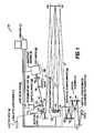
- FIG. 1is a schematic diagram of a scanning laser ophthalmoscope incorporating adaptive optics
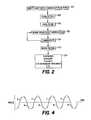
- FIG. 2is a flow chart of operational steps carried out with the ophthalmoscope of FIG. 1 ;
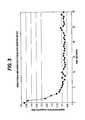
- FIG. 3is a graph of detected wavefront aberrations for multiple iterations of wavefront sensing and compensation
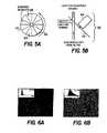
- FIG. 4is a graph of a horizontal angular position of a scanning line on the retina
- FIGS. 5A and 5Bare schematic diagrams of a time-share beam splitter usable in the ophthalmoscope of FIG. 1 ;
- FIGS. 6A and 6Bshow images of a retina taken without and with aberration correction, respectively;
- FIGS. 7A-7Cshow images taken of different axial sections of a retina
- FIG. 8shows a video image sequence in which a blood cell is moving through a retinal capillary
- FIG. 9shows images of cone cells taken at various locations on a retina and calculations of their spacing.
- FIG. 1shows a schematic diagram of the scanning laser ophthalmoscope using adaptive optics (AOSLO).
- AOSLOadaptive optics
- the AOSLO 100includes a light delivery section 102 , a light detection section 104 , a wavefront sensing section 106 , a wavefront compensation section 108 and a raster scanning section 110 . All five sections are under the control of a computer 112 .
- light from a fiber optic light source 114is expanded by a beam expander 116 and collimated by a collimating lens 118 .
- the collimated lightis made incident on an artificial pupil 120 to produce a smaller beam of light, which is injected into the common optical path O of the AOSLO 100 by a 5% reflecting beam splitter 122 .
- the wavefront compensation section 108includes a deformable mirror 128 .
- the deformable mirror 128includes a deformable mirror surface 130 deformed by multiple actuators (e.g., piezoelectric actuators) 132 .
- An example of a deformable mirroris the 37-channel deformable mirror produced by Xinetics, Andover, Mass.
- the deformable mirror 128is placed in the common optical path O conjugate to the entrance pupil of the eye E. Under the control of the computer 112 , the actuators 132 deform the mirror surface 130 to compensate for wavefront aberrations in a manner that will be described in detail below.
- a spherical mirror 134Light reflected from the mirror surface 132 is reflected to a spherical mirror 134 and thence to the raster scanning section 110 .
- the lightis reflected via a spherical mirror 136 to a horizontal scanning mirror 138 , which is implemented as a resonant scanner under control of the computer 112 .
- the light horizontally scanned by the horizontal scanning mirror 138is reflected via two spherical mirrors 140 and 142 to a vertical scanning mirror 144 , which is implemented as a galvanometric scanner under control of the computer 112 .
- a resonant scanner-galvanometric scanner combinationproduced by Electro-Optics Products Corp., Flushing Meadows, N.Y., can be used.
- the light which has been both horizontally and vertically scannedis reflected via spherical mirrors 146 and 148 to the retina of the eye E.
- the lightis scanned across an area of the retina whose extent is determined by the horizontal and vertical scanning extents of the scanning mirrors 138 and 144 , which in turn are controlled by the computer 112 .
- the beam splitter 150can be implemented as a partially reflecting mirror, although an active beam splitter will be described in detail below.
- the portion of the light diverted to the light detection section 104is focused by a lens 152 onto a confocal pinhole 154 which is in a plane conjugate to the retina.
- Light passing through the confocal pinhole 154is imaged by a photomultiplier tube 156 to produce signals which can be converted into an image by the computer 112 .
- the hardware usedcan be a GaAs photomultiplier tube from Hamamatsu, Japan, and a GenesisLC frame grabbing board from Matrox, California, Québec, Canada.
- the portion of the light passed to the wavefront sensing section 106is collimated by lenses 158 and 160 and is passed to a Hartmann-Shack detector 162 .
- the Hartmann-Shack detector 162includes a lenslet array 164 which breaks up the light into an array of spots and a CCD camera or other suitable imaging device 166 which images the spots.
- the deviation of each spot from the position which it would occupy in the absence of wavefront aberrationsallows a determination of those aberrations in the computer 112 .
- Techniques for determining the aberrations up to the tenth Zernike orderare known in the art.
- the computer 112uses those aberrations to control the deformable mirror 128 to compensate for those aberrations.
- a drawback of using mirrorsis that astigmatism and other aberrations are introduced when they are off axis.
- a cylindrical correctioncan be placed in the spectacle plane of the eye, and optical design software such as ZEMAX, published by Focus Software, Arlington, Ariz., can be used to minimize the remaining high-order system aberrations through optimal placement of the mirrors.
- optical design softwaresuch as ZEMAX, published by Focus Software, Arlington, Ariz., can be used to minimize the remaining high-order system aberrations through optimal placement of the mirrors.
- Off-the-shelf spherical reflecting mirrorscan be used.
- the AOSLO 100operates as shown in the flow chart of FIG. 2 .
- the light delivery section 102injects light into the common optical path O.
- the scanning section 110scans the retina.
- the retinacan be axially scanned, in a manner to be described below, to produce a three-dimensional image.
- step 208the wavefront sensing section 106 senses the wavefront aberrations.
- step 210the wavefront compensation section 108 compensates for those aberrations. Steps 208 and 210 can be performed iteratively.
- the light detection section 104images the retina.
- the image of the retinais used for any desired purpose, including diagnosis of the retinal condition, surgery on the retina, application of therapeutic laser light to the retina, or eye movement tracking, as will be explained in detail below.
- FIG. 3shows the results of such iterations for a 6.3 mm pupil in a living human eye.
- the x-axisis the time in seconds over which the correction took place.
- Each pointrepresents the root mean square aberration after a single iteration.
- the magnitude of aberrations, measured up to the tenth order in this case,is reduced sixfold for the 6.3 mm pupil.
- FIG. 4shows a graph of the horizontal angular position of the horizontally scanned line on the retina as a function of time. As shown, the position is a sinusoidal function of time, which has roughly linear sections.
- the scattered lightis detected by the light detection section 104 to image one line in a frame in which the retina is imaged.
- the scattered lightis passed to the wavefront sensing section 106 to measure the wavefront aberration.
- the structure of the beam splitter 150is shown in FIGS. 5A and 5B .
- the beam splitter 150includes a disk 502 rotated by a motor 504 .
- the disk 502has mirrored segments 506 alternating with non-mirrored segments 508 , so that the light is alternately reflected to the light detection section 104 and passed to the wavefront sensing section 106 .
- the reverse direction R of the scancan be used for wavefront sensing by splitting the light between the wavefront sensor and the photomultiplier tube with the segmented mirror that alternates between transmitting the light to the wavefront sensor and reflecting the beam toward the photomultiplier tube.
- the timing of the mirroris phase-locked to the horizontal scan frequency.
- the light reaching the wavefront sensorcan be integrated for any desired period of time independently of the scan rate or the frame rate of a typical AOSLO.
- the aberrations of the eyechange dynamically and so the image quality will be better if the eye's aberrations are measured and compensated while the retina is imaged.
- the deformable mirrorcan be used as an axial scanning element in axial sectioning.
- Axial sectioningrequires an optical correction to change the depth plane of the focused raster scan on the retina.
- the use of the deformable mirrorpresents some unique advantages, which include reducing the number of moving parts in the system, and increasing its speed and precision.
- the thickness of the retinais about 300 microns. A focal change of less than 1 diopter is sufficient to change the focal plane by this amount.
- the present methodcan be implemented with the deformable mirror described in the current design or it can be done with alternate, dynamic wavefront compensation techniques, such as micro-electrical machined (MEMs) deformable mirrors, or membrane mirrors.
- MEMsmicro-electrical machined
- Wavefront sensing and correctioncan be done simultaneously with axial sectioning, in a technique called “non-null wavefront compensation.”
- the optical path for wavefront sensingis not confocal, so light is detected from all scattered layers in the retina simultaneously. Therefore, when the aberrations of the eye are corrected, the defocus is also adjusted to put the focal plane into the mean location of all the scattering layers in the retina. If wavefront sensing and compensation were to be done simultaneously with axial sectioning, the mirror would continually try to adjust its defocus to move the image plane back to the mean location of the scattering surfaces. Such a correction would defeat attempts to change the focal plane of the system and image different layers of the retina. This is overcome in the following way.
- the AO systemis programmed to converge to a finite defocused state.
- the AO systemwill adjust the focal plane, while still correcting all other aberrations to zero. This technique will allow the operator to change the focal plane while still having the benefit of simultaneous wavefront sensing and compensation.
- the AOSLO described hereinpermits the direct imaging of features in the living retina that have never been observed, features that include retinal pigment epithelium cells, individual nerve fibers, cone and rod photoreceptors, single capillaries in the retina and choroid and white blood cells. With the improvements in axial sectioning, it will be possible to generate the first microscopic scale three-dimensional images of living human retina at high resolutions.
- the AOSLOcan be used for the diagnosis of retinal disorders like diabetic retinopathy, retinitis pigmentosa, age-related macular degeneration, or glaucoma.
- high-resolution images of the retinawill permit highly accurate measurements of eye movements needed for surgical applications or applications requiring eye tracking.
- stimuli or treatment lasersare projected directly onto the retina as part of the raster scan.
- Treatmentsinclude photodynamic therapy, laser microphotocoagulation, and microperimetry of the retina.
- the RMS wavefront error after AO compensationranged from 0.05 to 0.15 ⁇ m over a 6.3 mm pupil.
- the patientsused a dental impression mount fixed to an X-Y-Z translation stage to set and maintain eye alignment during the wavefront correction and imaging.
- the retinal location of the wavefront correction and imagingwas controlled by having each patient view a fixation target. A drop of 1% tropicamide was instilled to dilate the pupil and to minimize accommodation fluctuations.
- FIGS. 6A and 6Bshow the same area of the retina of one patient taken without ( FIG. 6A ) and with ( FIG. 6B ) aberration correction.
- the RMS wavefront errorwas reduced from 0.55 to 0.15 ⁇ m.
- Another advantagewas that correction of the aberrations caused more light to be focused through the confocal pinhole, thus increasing the amount of light for imaging.
- the inset in each of FIGS. 6A and 6Bshows a histogram of gray scales in the image.
- FIGS. 7A-7Cshow axial sectioning of the retina, which is possible because of the reduction in aberrations.
- the imagesare from a location 4.5 degrees superior to the fovea.
- the focal planeis at the surface of the nerve fibers.
- FIG. 7Bshows a slightly deeper optical section in which less nerve fiber is seen but the blood vessel is in focus.
- FIG. 7Cshows an image in which the focal plane is at the level of the photoreceptors, which are about 300 ⁇ m deeper than the image of FIG. 7 A.
- FIG. 8shows a sequence of video frames in which the passage of a white blood cell through the smallest retinal capillaries is directly observed in a living human eye.
- the scale bar at the bottomis 100 microns.
- FIG. 9shows images of cone photoreceptors resolved at retinal locations from 0.5 to 4 degrees from the fovea.
- the long-dashed lineshows data from Curcio et al, “Human photoreceptor topography,” J. Comp. Neurol. 1990; 292:497-523, while the short-dashed line shows psychophysical estimations of cone spacing from D. Williams, “Topography of the foveal cone mosaic in the living human eye,” Vision Res. 28, 433-454 (1988).
- Preliminary estimates of the resolution of the present inventionare about 2.5 ⁇ m lateral and about 100 ⁇ m axial.
- conventional SLO'shave a typical resolution of 5 ⁇ m lateral and 300 ⁇ m axial.
- the AOSLO of the preferred embodimentoperates at a frame rate of 30 Hz, which permits visualization of blood flow in the retinal capillaries. Also, the real-time imaging provides feedback on image quality and image location. Further, axial sectioning can be implemented. Conventional flood-illumination imaging, even with AO, cannot offer such advantages.
Landscapes
- Physics & Mathematics (AREA)
- Health & Medical Sciences (AREA)
- Life Sciences & Earth Sciences (AREA)
- Spectroscopy & Molecular Physics (AREA)
- General Physics & Mathematics (AREA)
- Biomedical Technology (AREA)
- Surgery (AREA)
- Engineering & Computer Science (AREA)
- Biophysics (AREA)
- Heart & Thoracic Surgery (AREA)
- Medical Informatics (AREA)
- Molecular Biology (AREA)
- Ophthalmology & Optometry (AREA)
- Animal Behavior & Ethology (AREA)
- General Health & Medical Sciences (AREA)
- Public Health (AREA)
- Veterinary Medicine (AREA)
- Optics & Photonics (AREA)
- Eye Examination Apparatus (AREA)
Abstract
Description
The present application claims the benefit of U.S. Provisional Application No. 60/316,173, filed Aug. 30, 2001, whose disclosure is hereby incorporated by reference in its entirety into the present disclosure.
The present invention was developed under NIH Grant No. R1 EY 13299-01 and NSF Grant No. AST 9876783. The government has certain rights in the invention.
The present invention is directed to scanning laser ophthalmoscopes (SLO) and methods of using them, and more particularly to such ophthalmoscopes and methods of using them which involve the use of adaptive optics (AO) to compensate for wavefront aberrations in the eye under examination.
The development of ocular imaging has progressed since the first scanning laser ophthalmoscope (SLO) was disclosed in U.S. Pat. No. 4,213,678. The first patent relating to imaging the ocular fundus while correcting for eye aberrations was Bille's patent titled, “Method and Apparatus for forming an image of the ocular fundus” (U.S. Pat. No. 4,579,430). A scanning laser ophthalmoscope for high lateral-resolution imaging was developed which was capable of imaging a living human eye but did not use adaptive optics (AO) and had limited resolution at the microscopic level.
The first published report of using AO in a SLO was by Dreher et al, “Active optical depth resolution improvement of the laser tomographic scanner,”App. Opt.28, 804-808 (1989), to improve the axial resolution of their instrument. The authors of that article did not use a wavefront sensor to measure the aberrations of the eye, and their wavefront corrector was used only to compensate for the astigmatism of the eye. Similarly, the axial resolution of a SLO has been improved by using a rigid contact lens to eliminate the aberrations of the cornea, and modest improvements in a fundus image has been obtained with a fundus camera equipped with a membrane deformable mirror. Liang et al, “Supernormal vision and high-resolution retinal imaging through adaptive optics,”J. Opt. Soc. Am. A14, 2884-2892 (1997), used an ophthalmoscope equipped with AO to image microscopic structures in the retina, but they did not apply the technology to a SLO.
In U.S. Pat. No. 6,095,651, a Hartmann-Shack wavefront sensor and wavefront compensation device are used to measure the high-order aberrations of the eye. A Hartmann-Shack wavefront sensor was also used by Bille in U.S. Pat. No. 6,155,684 to measure aberrations for wavefront compensation as a means to improve vision. A modified Hartmann-Shack wavefront sensor is described by Williams et al. in U.S. Pat. No. 6,199,986, wherein a method for real time measurement of the aberrations of the eye is described.
Therapeutic applications of SLOs with AO include microphotocoagulation and photodynamic therapy. In U.S. Pat. No. 6,186,628, Van de Velde describes the use of a scanning laser ophthalmoscope with an adaptive element for microphotocoagulation and photodynamic therapy. The wavefront sensing technique, described in another patent, entitled “Scanning laser ophthalmoscope for retinal microphotocoagulation and measurement of wavefront aberrations” (U.S. Pat. No. 5,943,117) employs a SLO to measure the wavefront aberrations of the eye. This technique is not used widely.
Although there are a number of patents covering SLO's, they do not propose a method for wavefront sensing whereby the light path is scanned/descanned using the same optics and light source as that used for imaging the ocular fundus. Methods that do not use the same optics for wavefront sensing and light detection are subject to a common phenomena called “non-common path errors,” where the aberrations on the path to the wavefront sensor are different than those reaching the light detector for imaging.
By implementing AO to measure and correct high-order aberrations in an areal imaging system, such as a CCD camera or a film camera, the quality of retinal images will be improved. However, areal imaging techniques are limited in that they cannot suppress light from layers in front of or behind the focal plane of the ophthalmoscope. Because of this limitation, the images may have high resolution, but will suffer from low contrast because of scattered light from structures outside of the best focal plane.
To date, there has been no successful application of AO into a SLO. The one previous design published by Dreher et al. did not include wavefront sensing in the measurement. The benefits of AO cannot be realized without wavefront sensing being an integral part of the system. Bille's above-cited patent describes a design for a SLO that integrates a wavefront sensor into the design, but it does not use the same path as the light detection path and is therefore subject to the problem of non-common path errors.
It will be apparent from the above that a need exists in the art to integrate adaptive optics into retinal imaging. It is therefore an object of the invention to provide a scanning laser ophthalmoscope with adaptive optics.
It is another object of the invention to do so while avoiding non-common path errors.
It is a further object of the invention to provide axial sectioning in a scanning laser ophthalmoscope.
To achieve the above and other objects, the present invention is directed to a system and method whereby AO can be efficiently and effectively implemented in a scanning laser ophthalmoscope. The present invention will be an improvement on instruments used to take microscopic images of the retina in living human eyes and will have improved optical sectioning capability over currently available SLO's.
The present invention's implementation of AO is efficient because it uses the same optical path as the SLO. The present invention's implementation is effective because it is designed to optimize image quality, both axially and laterally, over the entire field of view of the ophthalmoscope.
The SLO is a device used to take images of the retina of a living human eye. In the SLO, scattered light is measured from a focused spot of light as it is scanned across the retina in a raster pattern. The image is built over time, pixel by pixel, as the spot moves across the retina. An aperture conjugate to (in the image plane of) the desired focal plane in the retina and prior to the light detector can be used to reduce scattered light originating from planes other than the plane of focus. The confocal aperture can be used to do optical slicing, or imaging of different layers in the human retina.
AO describes a set of techniques to measure and compensate for aberrations, or optical defects, in optical systems. AO, when applied to the optical system of the eye, can provide substantial improvements in the sharpness of retinal images that are normally degraded from the aberrations. Implementation of AO requires the use of a wavefront sensor, which is a device to measure the aberrations of the optical system, and a wavefront corrector, which is a device used to compensate for the aberrations in an optical system.
In one particular embodiment, the adaptive optics scanning laser ophthalmoscope (AOSLO) can be broken down into five main components: light delivery, light detection, wavefront sensing, wavefront compensation and raster scanning.
(i) Light delivery: Light delivery can be from a plurality of laser sources of different wavelengths, depending on the application. Light is relayed through the instrument via mirrors, which do not suffer from chromatic aberration. Furthermore, unlike lenses, mirrors do not produce back reflections that can enter into the light detection arm.
(ii) Light detection: Light is detected with a detector such as a very sensitive light detector and amplifier; in a preferred embodiment, a photomultiplier tube is used. Prior to the light detector in the preferred embodiment is the confocal pinhole, which is placed conjugate to the focal plane of the system. The confocal pinhole is used to limit light reaching the detector to that originating from the plane of focus.
(iii) Wavefront sensing: Wavefront sensing takes place in the detection arm of the instrument. The wavefront sensor measures the optical defects of the eye in the plane of the entrance pupil.
(iv) Wavefront compensation: Wavefront compensation is done with adaptive optics such as a deformable mirror. The shape of the deformable mirror is set to exactly compensate the distortions in the light that are caused by the aberrations of the eye.
(v) Raster scanning: Raster scanning is used to move the focused spot across the retina in a raster pattern. The extent of the pattern defines the area of the retina that is being imaged. Positional outputs from the scanning mirrors, combined with scattered intensity information from the light detector, are used to reconstruct the retinal image. Setting the sweep angle on the scanning mirrors controls the field size of the image.
During operation of the embodiment just described, light is being scanned in a raster pattern across the retina. The input light beam is stationary from light delivery through the deformable mirror and up to the first scanning mirror. The horizontal scanning mirror adds a horizontal sweeping motion to the beam. The second scanning mirror adds a vertical sweep to the beam. Both sweeping motions are done in planes that are optically conjugate to the pupil of the eye so that the beam at the plane of the pupil is stationary but it still makes a raster pattern on the retina. This property is accomplished by using relay optics between each beam-altering element in the system. According to the law of reversibility of light, the scattered light from the focused spot on the retina returns along the same path that the light traveled to generate the spot. In other words, the scattered light follows the scanning beam but in the opposite direction. The scattered light also gets descanned after passing through the same raster scanning mirrors. By the time the returning light has passed the horizontal scanning mirror, the beam is again stationary. Aberrations in the scattered light are compensated by the deformable mirror and are bounced off a beam splitter into the light detection and wavefront sensing path of the AOSLO. Having a stationary beam in the light detection arm allows the scattered light to be focused through a fixed confocal pinhole, which gives the SLO its optical sectioning capability.
Light is scanned over the retina in a raster pattern while the beam remains stationary in the plane of the pupil. After scattering, the optics of the SLO descan the beam and image the pupil of the eye onto the lenslet array of the Hartmann-Shack wavefront sensor, or the corresponding element of another wavefront sensor, e.g., a scanning wavefront sensor. The pupil is conjugate to the lenslet array, which means that the aberrations are measured in the pupil plane of the eye. The focused spots in the Hartmann-Shack wavefront sensor image are also stationary because the beam has been descanned. An image of the focused spot array in the Hartmann-Shack sensor is obtained by taking a time exposure of the focused spots with a CCD array detector. These spot images are analyzed to determine the aberrations of the eye being measured. In a typical Hartmann-Shack wavefront measurement, the aberrations are measured for light originating from a stationary focused spot on the retina. In high-speed ophthalmic Hartmann-Shack applications, a system that employs a linear scanning spot has been developed. In this implementation, the source of the light on the retina is constantly moving in a raster during the time exposure, and the Hartmann-Shack sensor measures the average wavefront aberration over the entire field of the image. The aberration over the image field is expected to change slightly because aberrations change with off-axis object position. Nonetheless, these changes are small since it has been demonstrated that the eye is nearly isoplanatic over a one-degree field. Therefore, the use of a scanning beam as the source does not present a disadvantage to the measurement, but rather it presents several unique advantages, which are listed below:
1) By using the same light source for wavefront sensing and imaging, the optics are simplified (no additional light source is necessary for wavefront sensing), and no correction has to be made for the chromatic aberration of the eye between the wavefront sensing and imaging wavelengths.
2) Wavefront sensing is always done on the same retinal region as the images that are taken, since the source of the wavefront measurement is also the imaging light.
3) Measuring and compensating the average wavefront over the entire image field will result in a more uniform correction for aberrations, which will result in better image quality over the field.
4) Wavefront measurements are not affected by noise due to laser speckle since the time-averaged image of a moving spot on the retina despeckles the image. This advantage has already been applied to wavefront sensing but not to its application for SLO.
5) The wavefront-sensing configuration described here is easily adaptable to real-time wavefront sensing and compensation. This advantage stems from the fact that the wavefront sensing signal is always present during imaging since imaging and wavefront sensing use the same light source.
6) The optical path to the wavefront sensor is the same as to the photomultiplier, with the exception of three aberration-corrected achromatic lenses (two in the wavefront sensor path and one in the photomultiplier path). The aberrations that are measured in the wavefront sensor will be the same as the aberrations of the light reaching the confocal pinhole, which reduces the non-common path errors.
In at least one embodiment, the wavefront compensation is done with a deformable mirror (DM) placed conjugate to the pupil in the stationary part of the optical path, prior to the raster scanning mirrors. Having the DM in this part of the path means that the mirrors that are used to focus the pupil image onto the DM can be as small as the maximum beam diameter and do not have to be enlarged to enclose the maximum scan angle. This reduces the size and cost of the instrument and maintains better image quality in the optics of the instrument.
By using AO in a SLO, the lateral resolution of retinal images is expected to improve by up to three times. This has already been demonstrated in conventional ophthalmoscopes equipped with AO. The main advantage of applying AO in a SLO will be the improvements in axial resolution. The axial resolution may be improved by up to 10 times over conventional SLO's.
Equivalent Technologies: Successful implementation of AO in a SLO does not rely on the specific technologies described in this disclosure. The following two paragraphs describe equivalent AO technologies that can be implemented with the same advantages.
Any wavefront sensing technology can be employed that is based on objective measurement and does not rely on coherent light to perform the wavefront measurement. Alternative techniques include but are not limited to laser ray tracing techniques, Tscherning aberroscopic techniques and crossed-cylinder aberrometer techniques.
Any wavefront compensation technique can be employed that does not rely on the use of coherent light. Alternative methods for wavefront sensing include, but are not limited to, liquid crystal spatial light modulators, micro-electro-machined (MEMs) membrane mirrors, MEMs segmented mirrors, bimorph deformable mirrors and electrostatic membrane deformable mirrors.
One set of applications involves the direct imaging applications that will benefit from high-resolution images. Such applications include the early diagnosis of retinal disorders like diabetic retinopathy, retinitis pigmentosa, age-related macular degeneration, or glaucoma. Other applications will be to visualize structures in the retina such as the nerve fibers, cone and rod photoreceptors, single capillaries in the retina and choroid, and retinal pigmented epithelium cells. High-resolution imaging will help retinal surgeons maintain a sharper image of the retina during retinal surgery.
Another set of applications are those whereby the SLO is used to image the retina at 30 frames per second and is used to observe directly the flow of single white blood cells.
Another set of applications are those where stimuli or treatment lasers are projected directly onto the retina as part of the raster scan. These applications include photodynamic therapy, laser microphotocoagulation, microperimetry of the retina, and eye tracking.
The SLO can use a confocal pinhole to suppress light from outside of the focal plane, which gives the SLO its optical slicing capability. This property of the SLO can be improved by implementing AO to measure and correct the aberrations of the eye. By reducing the aberrations of the eye through AO compensation, both axial and lateral resolution can be improved.
A preferred embodiment of the present invention and variations thereof will be disclosed in detail with reference to the drawings, in which:
A preferred embodiment of the present invention and variations thereof will now be set forth in detail with reference to the drawings, in which like reference numerals refer to like elements or operational steps throughout.
As mentioned above, theAOSLO 100 includes alight delivery section 102, alight detection section 104, awavefront sensing section 106, awavefront compensation section 108 and araster scanning section 110. All five sections are under the control of acomputer 112.
In thelight delivery section 102, light from a fiber opticlight source 114 is expanded by abeam expander 116 and collimated by acollimating lens 118. The collimated light is made incident on anartificial pupil 120 to produce a smaller beam of light, which is injected into the common optical path O of theAOSLO 100 by a 5% reflecting beam splitter122.
Once in the optical path O, the light is reflected byspherical mirrors 124 and126 to thewavefront compensation section 108. Mirrors are used both to fold the optical path, thereby making the system more compact, and to avoid the problems of chromatic aberration and back reflection that affect lenses. Thewavefront compensation section 108 includes adeformable mirror 128. As known in the art, thedeformable mirror 128 includes adeformable mirror surface 130 deformed by multiple actuators (e.g., piezoelectric actuators)132. An example of a deformable mirror is the 37-channel deformable mirror produced by Xinetics, Andover, Mass. Thedeformable mirror 128 is placed in the common optical path O conjugate to the entrance pupil of the eye E. Under the control of thecomputer 112, theactuators 132 deform themirror surface 130 to compensate for wavefront aberrations in a manner that will be described in detail below.
Light reflected from themirror surface 132 is reflected to aspherical mirror 134 and thence to theraster scanning section 110. In theraster scanning section 110, the light is reflected via aspherical mirror 136 to ahorizontal scanning mirror 138, which is implemented as a resonant scanner under control of thecomputer 112. The light horizontally scanned by thehorizontal scanning mirror 138 is reflected via twospherical mirrors computer 112. A resonant scanner-galvanometric scanner combination produced by Electro-Optics Products Corp., Flushing Meadows, N.Y., can be used. The light which has been both horizontally and vertically scanned is reflected viaspherical mirrors computer 112.
Light reflected from the retina of the eye E travels back along the common optical path O, in which it is descanned by the scanning mirrors144 and138, to abeam splitter 150 to be split between thelight detection section 104 and thewavefront sensing section 106. Thebeam splitter 150 can be implemented as a partially reflecting mirror, although an active beam splitter will be described in detail below.
The portion of the light diverted to thelight detection section 104 is focused by alens 152 onto a confocal pinhole154 which is in a plane conjugate to the retina. Light passing through the confocal pinhole154 is imaged by aphotomultiplier tube 156 to produce signals which can be converted into an image by thecomputer 112. The hardware used can be a GaAs photomultiplier tube from Hamamatsu, Japan, and a GenesisLC frame grabbing board from Matrox, Montréal, Québec, Canada.
The portion of the light passed to thewavefront sensing section 106 is collimated bylenses Shack detector 162. As known in the art, the Hartmann-Shack detector 162 includes alenslet array 164 which breaks up the light into an array of spots and a CCD camera or othersuitable imaging device 166 which images the spots. The deviation of each spot from the position which it would occupy in the absence of wavefront aberrations allows a determination of those aberrations in thecomputer 112. Techniques for determining the aberrations up to the tenth Zernike order are known in the art. Thecomputer 112 uses those aberrations to control thedeformable mirror 128 to compensate for those aberrations.
A drawback of using mirrors is that astigmatism and other aberrations are introduced when they are off axis. To overcome that drawback, a cylindrical correction can be placed in the spectacle plane of the eye, and optical design software such as ZEMAX, published by Focus Software, Tucson, Ariz., can be used to minimize the remaining high-order system aberrations through optimal placement of the mirrors. Off-the-shelf spherical reflecting mirrors can be used.
TheAOSLO 100 operates as shown in the flow chart of FIG.2. Instep 202, thelight delivery section 102 injects light into the common optical path O. Instep 204, thescanning section 110 scans the retina. In anoptional step 206, the retina can be axially scanned, in a manner to be described below, to produce a three-dimensional image.
Instep 208, thewavefront sensing section 106 senses the wavefront aberrations. Instep 210, thewavefront compensation section 108 compensates for those aberrations.Steps
Instep 212, thelight detection section 104 images the retina. Instep 214, the image of the retina is used for any desired purpose, including diagnosis of the retinal condition, surgery on the retina, application of therapeutic laser light to the retina, or eye movement tracking, as will be explained in detail below.
As just noted, the steps of sensing and compensating the wavefront aberrations can be performed iteratively.FIG. 3 shows the results of such iterations for a 6.3 mm pupil in a living human eye. The x-axis is the time in seconds over which the correction took place. Each point represents the root mean square aberration after a single iteration. The magnitude of aberrations, measured up to the tenth order in this case, is reduced sixfold for the 6.3 mm pupil.
A specific embodiment of thebeam splitter 150 and its operation, namely, the timeshare embodiment, will be described.FIG. 4 shows a graph of the horizontal angular position of the horizontally scanned line on the retina as a function of time. As shown, the position is a sinusoidal function of time, which has roughly linear sections. During the linear section of each forward scan F, the scattered light is detected by thelight detection section 104 to image one line in a frame in which the retina is imaged. During the linear section of each reverse scan R, the scattered light is passed to thewavefront sensing section 106 to measure the wavefront aberration.
The structure of thebeam splitter 150 is shown inFIGS. 5A and 5B . Thebeam splitter 150 includes adisk 502 rotated by amotor 504. Thedisk 502 has mirroredsegments 506 alternating withnon-mirrored segments 508, so that the light is alternately reflected to thelight detection section 104 and passed to thewavefront sensing section 106.
The reverse direction R of the scan can be used for wavefront sensing by splitting the light between the wavefront sensor and the photomultiplier tube with the segmented mirror that alternates between transmitting the light to the wavefront sensor and reflecting the beam toward the photomultiplier tube. The timing of the mirror is phase-locked to the horizontal scan frequency. The light reaching the wavefront sensor can be integrated for any desired period of time independently of the scan rate or the frame rate of a typical AOSLO. The aberrations of the eye change dynamically and so the image quality will be better if the eye's aberrations are measured and compensated while the retina is imaged.
The deformable mirror can be used as an axial scanning element in axial sectioning. Axial sectioning requires an optical correction to change the depth plane of the focused raster scan on the retina. The use of the deformable mirror presents some unique advantages, which include reducing the number of moving parts in the system, and increasing its speed and precision. The thickness of the retina is about 300 microns. A focal change of less than 1 diopter is sufficient to change the focal plane by this amount.
The present method can be implemented with the deformable mirror described in the current design or it can be done with alternate, dynamic wavefront compensation techniques, such as micro-electrical machined (MEMs) deformable mirrors, or membrane mirrors.
Wavefront sensing and correction can be done simultaneously with axial sectioning, in a technique called “non-null wavefront compensation.” The optical path for wavefront sensing is not confocal, so light is detected from all scattered layers in the retina simultaneously. Therefore, when the aberrations of the eye are corrected, the defocus is also adjusted to put the focal plane into the mean location of all the scattering layers in the retina. If wavefront sensing and compensation were to be done simultaneously with axial sectioning, the mirror would continually try to adjust its defocus to move the image plane back to the mean location of the scattering surfaces. Such a correction would defeat attempts to change the focal plane of the system and image different layers of the retina. This is overcome in the following way. Rather than letting the AO system converge to a null state (i.e., zero aberrations), the AO system is programmed to converge to a finite defocused state. By converging to a defocused state, the AO system will adjust the focal plane, while still correcting all other aberrations to zero. This technique will allow the operator to change the focal plane while still having the benefit of simultaneous wavefront sensing and compensation.
The AOSLO described herein permits the direct imaging of features in the living retina that have never been observed, features that include retinal pigment epithelium cells, individual nerve fibers, cone and rod photoreceptors, single capillaries in the retina and choroid and white blood cells. With the improvements in axial sectioning, it will be possible to generate the first microscopic scale three-dimensional images of living human retina at high resolutions.
The AOSLO can be used for the diagnosis of retinal disorders like diabetic retinopathy, retinitis pigmentosa, age-related macular degeneration, or glaucoma.
In still another use, high-resolution images of the retina will permit highly accurate measurements of eye movements needed for surgical applications or applications requiring eye tracking.
In yet another use, stimuli or treatment lasers are projected directly onto the retina as part of the raster scan. Treatments include photodynamic therapy, laser microphotocoagulation, and microperimetry of the retina.
Images have been collected from the eyes of five persons ranging in age from the 2ndto 7thdecade. The RMS wavefront error after AO compensation ranged from 0.05 to 0.15 μm over a 6.3 mm pupil. The patients used a dental impression mount fixed to an X-Y-Z translation stage to set and maintain eye alignment during the wavefront correction and imaging. The retinal location of the wavefront correction and imaging was controlled by having each patient view a fixation target. A drop of 1% tropicamide was instilled to dilate the pupil and to minimize accommodation fluctuations.
Experimental data will now be set forth. The correction of aberrations provided by the present invention permits retinal imaging of high quality, as will be seen.
Preliminary estimates of the resolution of the present invention are about 2.5 μm lateral and about 100 μm axial. By contrast, conventional SLO's have a typical resolution of 5 μm lateral and 300 μm axial.
The AOSLO of the preferred embodiment operates at a frame rate of 30 Hz, which permits visualization of blood flow in the retinal capillaries. Also, the real-time imaging provides feedback on image quality and image location. Further, axial sectioning can be implemented. Conventional flood-illumination imaging, even with AO, cannot offer such advantages.
The following article concerning the present invention is hereby incorporated by reference in its entirety into the present disclosure: A. Roorda et al, “Adaptive optics scanning laser ophthalmoscopy,”Optics Express,Vol. 10, No. 9, May 6, 2002, pp. 405-412.
While a preferred embodiment of the present invention and variations thereon have been disclosed above, those skilled in the art who have reviewed the present disclosure will readily appreciate that other embodiments can be realized within the scope of the invention. For example, numerical values are illustrative rather than limiting. Also, variations on the configuration of the common optical path are possible, and variations on the hardware have been noted above. Further, while the present invention has been disclosed with regard to human subjects, veterinary applications are also possible. Therefore, the present invention should be construed as limited only by the appended claims.
Claims (30)
1. A method of imaging an area of a retina of a living eye, the method comprising:
(a) providing light from a light source;
(b) injecting the light from the light source into a common optical path;
(c) performing a two-dimensional transverse scan of a focused spot of the light from the light source on the area of the retina;
(d) receiving light reflected from the focused spot on the retina back into the common optical path;
(e) from a first portion of the light reflected from the retina, detecting a wavefront aberration of the eye;
(f) disposing an adaptive optical element in the common optical path between the light source and the eye;
(g) controlling the adaptive optical element to compensate for the wavefront aberration in the light scanned on the area of the retina to project the focused spot onto the retina;
(h) controlling the adaptive optical element to compensate for the wavefront aberration in the light reflected from the focused spot on the retina back into the common optical path; and
(i) from a second portion of the light reflected from the retina, producing an image of the area of the retina.
2. The method ofclaim 1 , wherein step (d) comprises descanning the light reflected from the retina.
3. The method ofclaim 1 , wherein the adaptive optical element comprises a deformable mirror.
4. The method ofclaim 1 , wherein step (c) comprises raster scanning a light spot on the retina.
5. The method ofclaim 4 , wherein the raster scanning is performed with at least one scanning mirror.
6. The method ofclaim 5 , wherein step (c) further comprises controlling a sweep angle of the at least one scanning mirror to control a size of an area on the retina which is scanned.
7. The method ofclaim 1 , wherein step (e) is performed with a Hartmann-Shack detector.
8. The method ofclaim 7 , wherein:
step (i) is performed with a photodetector; and
the method further comprises providing a beam splitter in the common optical path to split the light reflected from the retina between the Hartmann-Shack detector and the photodetector.
9. The method ofclaim 8 , wherein the beam splitter comprises a rotating mirror having mirrored segments and transparent segments for time division of the light reflected from the retina.
10. The method ofclaim 9 , wherein a period of the time division equals a period of the scanning of step (c).
11. The method ofclaim 1 , wherein steps (e) and (g) are performed iteratively.
12. The method ofclaim 1 , wherein steps (e) and (i) are performed concurrently.
13. The method ofclaim 1 , further comprising (j) controlling the adaptive optical element for axial sectioning.
14. The method ofclaim 13 , wherein step (g) comprises correcting the focus to a non-null state.
15. The method ofclaim 13 , wherein step (i) comprises producing a three-dimensional image of the retina.
16. The method ofclaim 1 , further comprising using the image to diagnose a disorder of the retina.
17. The method ofclaim 1 , further comprising using the image to track movement of the eye.
18. The method ofclaim 1 , wherein step (c) comprises projecting a stimulus or treatment to the retina.
19. The method ofclaim 1 , wherein step (i) is performed a plurality of times to form a sequence of said images, and further comprising using the sequence of said images to measure a flow of blood cells in at least one capillary of the retina.
20. The method ofclaim 1 , wherein step (i) is performed with a confocal pinhole and a photodetector.
21. A system for imaging an area of a retina of a living eye, the system comprising:
a light delivery section, comprising a light source, for providing light from the light source and for injecting the light from the light source into a common optical path;
a scanning section for performing a transverse two-dimensional scan of a focused soot of the light from the light source on the area of the retina such that light reflected from the focused spot on the retina is received back into the common optical path;
a wavefront sensing section, receiving a first portion of the light reflected from the retina, for detecting a wavefront aberration of the eye;
a wavefront compensation section, comprising an adaptive optical element disposed in the common optical path between the light source and the eye, for compensating for the wavefront aberration in the light scanned on the area of the retina to project the focused spot onto the retina and for compensating for the wavefront aberration in the light reflected from the focused spot on the retina back into the common optical path; and
a light detection section, receiving a second portion of the light reflected from the retina, for producing an image of the area of the retina.
22. The system ofclaim 21 , wherein the scanning section descans the light reflected from the retina.
23. The system ofclaim 21 , wherein the adaptive optical element comprises a deformable mirror.
24. The system ofclaim 21 , wherein the scanning section comprises a device for raster scanning a light spot on the retina.
25. The system ofclaim 24 , wherein the device for raster scanning comprises at least one scanning mirror.
26. The system ofclaim 21 , wherein the wavefront sensing section comprises a Hartmann-Shack detector.
27. The system ofclaim 26 , wherein;
the light detection section comprises a photodetector; and
the system further comprises a beam splitter in the common optical path for splitting the light reflected from the retina between the Hartmann-Shack detector and the photodetector.
28. The system ofclaim 27 , wherein the beam splitter comprises a rotating mirror having mirrored segments and transparent segments for time division of the light reflected from the retina.
29. The system ofclaim 21 , wherein the light detection section comprises a confocal pinhole.
30. The method ofclaim 14 , wherein steps (e) and (g) are performed iteratively to correct the focus to the non-null state.
Priority Applications (2)
| Application Number | Priority Date | Filing Date | Title |
|---|---|---|---|
| US10/231,491US6890076B2 (en) | 2001-08-30 | 2002-08-30 | Method and apparatus for using adaptive optics in a scanning laser ophthalmoscope |
| US11/125,331US7118216B2 (en) | 2001-08-30 | 2005-05-10 | Method and apparatus for using adaptive optics in a scanning laser ophthalmoscope |
Applications Claiming Priority (2)
| Application Number | Priority Date | Filing Date | Title |
|---|---|---|---|
| US31617301P | 2001-08-30 | 2001-08-30 | |
| US10/231,491US6890076B2 (en) | 2001-08-30 | 2002-08-30 | Method and apparatus for using adaptive optics in a scanning laser ophthalmoscope |
Related Child Applications (1)
| Application Number | Title | Priority Date | Filing Date |
|---|---|---|---|
| US11/125,331ContinuationUS7118216B2 (en) | 2001-08-30 | 2005-05-10 | Method and apparatus for using adaptive optics in a scanning laser ophthalmoscope |
Publications (2)
| Publication Number | Publication Date |
|---|---|
| US20030053026A1 US20030053026A1 (en) | 2003-03-20 |
| US6890076B2true US6890076B2 (en) | 2005-05-10 |
Family
ID=23227824
Family Applications (2)
| Application Number | Title | Priority Date | Filing Date |
|---|---|---|---|
| US10/231,491Expired - LifetimeUS6890076B2 (en) | 2001-08-30 | 2002-08-30 | Method and apparatus for using adaptive optics in a scanning laser ophthalmoscope |
| US11/125,331Expired - LifetimeUS7118216B2 (en) | 2001-08-30 | 2005-05-10 | Method and apparatus for using adaptive optics in a scanning laser ophthalmoscope |
Family Applications After (1)
| Application Number | Title | Priority Date | Filing Date |
|---|---|---|---|
| US11/125,331Expired - LifetimeUS7118216B2 (en) | 2001-08-30 | 2005-05-10 | Method and apparatus for using adaptive optics in a scanning laser ophthalmoscope |
Country Status (4)
| Country | Link |
|---|---|
| US (2) | US6890076B2 (en) |
| EP (1) | EP1427328B1 (en) |
| JP (1) | JP4157839B2 (en) |
| WO (1) | WO2003020121A1 (en) |
Cited By (34)
| Publication number | Priority date | Publication date | Assignee | Title |
|---|---|---|---|---|
| US20060007534A1 (en)* | 2000-12-26 | 2006-01-12 | Olympus Corporation | Scanning optical microscope |
| US20070247638A1 (en)* | 2006-04-13 | 2007-10-25 | Mette Owner-Petersen | Multi-object wavefront sensor with spatial filtering |
| US20070252951A1 (en)* | 2006-04-24 | 2007-11-01 | Hammer Daniel X | Stabilized retinal imaging with adaptive optics |
| US20070263171A1 (en)* | 2006-05-01 | 2007-11-15 | Ferguson R D | Hybrid spectral domain optical coherence tomography line scanning laser ophthalmoscope |
| US20070291230A1 (en)* | 2006-06-16 | 2007-12-20 | Kabushiki Kaisha Topcon | Ophthalmologic photographing apparatus |
| US20070291229A1 (en)* | 2006-06-16 | 2007-12-20 | Kabushiki Kaisha Topcon | Ophthalmologic imaging apparatus |
| US20080218694A1 (en)* | 2006-10-18 | 2008-09-11 | Lawrence Livermore National Security, Llc. | High-resolution Adaptive Optics Scanning Laser Ophthalmoscope with Multiple Deformable Mirrors |
| US20080297723A1 (en)* | 2004-06-17 | 2008-12-04 | Amo Manufacturing Usa, Llc | Correction of Presbyopia Using Adaptive Optics, Wavefront Sensor Eye Alignment and Light Shield, and Associated Methods |
| US20100195093A1 (en)* | 2007-02-14 | 2010-08-05 | The Institute For Eye Research Limited | Characterization of optical systems |
| US20100195048A1 (en)* | 2009-01-15 | 2010-08-05 | Physical Sciences, Inc. | Adaptive Optics Line Scanning Ophthalmoscope |
| US7802883B2 (en) | 2007-12-20 | 2010-09-28 | Johnson & Johnson Vision Care, Inc. | Cosmetic contact lenses having a sparkle effect |
| US20110194072A1 (en)* | 2006-10-18 | 2011-08-11 | Olivier Scot S | Compact adaptive optic-optical coherence tomography system |
| US20110234978A1 (en)* | 2010-01-21 | 2011-09-29 | Hammer Daniel X | Multi-functional Adaptive Optics Retinal Imaging |
| CN102670164A (en)* | 2011-02-25 | 2012-09-19 | 佳能株式会社 | Image processing device, imaging system, and image processing method |
| US8346345B2 (en) | 2004-01-21 | 2013-01-01 | University Of Washington | Methods for assessing a physiological state of a mammalian retina |
| US8746884B2 (en) | 2009-04-13 | 2014-06-10 | Canon Kabushiki Kaisha | Optical image acquisition apparatus having adaptive optics and control method for the same |
| US8777413B2 (en) | 2006-01-20 | 2014-07-15 | Clarity Medical Systems, Inc. | Ophthalmic wavefront sensor operating in parallel sampling and lock-in detection mode |
| US8820929B2 (en) | 2006-01-20 | 2014-09-02 | Clarity Medical Systems, Inc. | Real-time measurement/display/record/playback of wavefront data for use in vision correction procedures |
| US8827452B2 (en) | 2006-01-20 | 2014-09-09 | Clarity Medical Systems, Inc. | Optimizing vision correction procedures |
| US8857985B2 (en) | 2006-01-20 | 2014-10-14 | Clarity Medical Systems, Inc. | Large diopter range real time sequential wavefront sensor |
| US8882270B2 (en) | 2006-01-20 | 2014-11-11 | Clarity Medical Systems, Inc. | Apparatus and method for operating a real time large diopter range sequential wavefront sensor |
| US20150208915A1 (en)* | 2014-01-29 | 2015-07-30 | University Of Rochester | System and method for observing an object in a blood vessel |
| US9101292B2 (en) | 2006-01-20 | 2015-08-11 | Clarity Medical Systems, Inc. | Apparatus and method for operating a real time large dipoter range sequential wavefront sensor |
| US9144380B2 (en) | 2012-12-10 | 2015-09-29 | Canon Kabushiki Kaisha | Adaptive optical apparatus, image obtaining apparatus, method for controlling adaptive optical apparatus, and storage medium |
| US9265458B2 (en) | 2012-12-04 | 2016-02-23 | Sync-Think, Inc. | Application of smooth pursuit cognitive testing paradigms to clinical drug development |
| US9380976B2 (en) | 2013-03-11 | 2016-07-05 | Sync-Think, Inc. | Optical neuroinformatics |
| USRE46099E1 (en)* | 2003-07-30 | 2016-08-09 | Asml Holding N.V. | Method of using deformable mirror using piezoelectric actuators formed as an integrated circuit |
| US20160249803A1 (en)* | 2015-02-26 | 2016-09-01 | Canon Kabushiki Kaisha | Focusing system and method |
| US9498119B2 (en) | 2013-11-14 | 2016-11-22 | Canon Kabushiki Kaisha | Adaptive optics system and control method of the same, testing apparatus and control method of the same, information processing apparatus and control method of the same, and computer-readable storage medium |
| US9740003B2 (en) | 2012-10-12 | 2017-08-22 | Thorlabs, Inc. | Compact, low dispersion, and low aberration adaptive optics scanning system and method |
| US9918631B2 (en) | 2012-11-09 | 2018-03-20 | Canon Kabushiki Kaisha | Adaptive optical apparatus and ophthalmic apparatus |
| US10052018B2 (en) | 2016-04-06 | 2018-08-21 | Canon Kabushiki Kaisha | Wavefront measuring method for adaptive optics system |
| US10130253B2 (en) | 2014-11-07 | 2018-11-20 | The Regents Of The University Of California | Scanning laser ophthalmoscope for real-time eye tracking and method of operating same |
| US12433480B2 (en) | 2021-12-17 | 2025-10-07 | The Trustees Of Indiana University | Methods, systems, and devices for vision testing |
Families Citing this family (79)
| Publication number | Priority date | Publication date | Assignee | Title |
|---|---|---|---|---|
| WO2003105678A2 (en)* | 2002-06-12 | 2003-12-24 | Advanced Research And Technology Institute, Inc. | Method and apparatus for improving both lateral and axial resolution in ophthalmoscopy |
| US20080269731A1 (en)* | 2003-11-19 | 2008-10-30 | Casimir Andrew Swinger | Method and apparatus applying patient-verified prescription of high order aberrations |
| DE10360570B4 (en)* | 2003-12-22 | 2006-01-12 | Carl Zeiss | Optical measuring system and optical measuring method |
| FR2865370B1 (en)* | 2004-01-22 | 2006-04-28 | Centre Nat Rech Scient | SYSTEM AND METHOD FOR IN VIVO TOMOGRAPHY WITH HIGH LATERAL AND AXIAL RESOLUTION OF THE HUMAN RETINA |
| FR2865538B1 (en) | 2004-01-22 | 2007-10-19 | Centre Nat Rech Scient | DEVICE AND METHOD FOR MEASURING FRONT CONTRAST IN A MICHELSON INTERFEROMETER, AND EYE EXAMINATION SYSTEM INCLUDING SUCH A DEVICE |
| FR2865371B1 (en) | 2004-01-22 | 2007-12-21 | Centre Nat Rech Scient | DEVICE AND METHOD FOR EXAMINING THE EYE, SYSTEM FOR EXAMINING THE EYE BY IN VIVO TOMOGRAPHY EQUIPPED WITH SAID DEVICE |
| JP4510534B2 (en) | 2004-06-22 | 2010-07-28 | 株式会社トプコン | Optical characteristic measuring device and fundus image observation device |
| EP1632170B1 (en) | 2004-09-01 | 2013-03-20 | WaveLight GmbH | Fast wavefront measurement |
| US7365856B2 (en) | 2005-01-21 | 2008-04-29 | Carl Zeiss Meditec, Inc. | Method of motion correction in optical coherence tomography imaging |
| DE102005007911A1 (en)* | 2005-02-08 | 2006-08-10 | Hensoldt Ag | Digital camera e.g. digital photo camera, for telescope, has ray distributor with rotary disc having areas that are arranged on disc to direct light ray towards view finder and image recording medium in respective rotary positions of disc |
| US7805009B2 (en) | 2005-04-06 | 2010-09-28 | Carl Zeiss Meditec, Inc. | Method and apparatus for measuring motion of a subject using a series of partial images from an imaging system |
| JP4653577B2 (en)* | 2005-07-08 | 2011-03-16 | 株式会社ニデック | Ophthalmic imaging equipment |
| JP4947387B2 (en)* | 2005-08-18 | 2012-06-06 | イマジン アイズ | Method and system for correcting ocular aberrations applied to ophthalmic instruments |
| GB2429522A (en)* | 2005-08-26 | 2007-02-28 | Univ Kent Canterbury | Optical mapping apparatus |
| DE102005054691A1 (en) | 2005-11-16 | 2007-05-24 | Bausch & Lomb Inc. | Method and device for determining the visual acuity of an eye |
| US7652759B1 (en) | 2006-02-23 | 2010-01-26 | Rockwell Automation Technologies, Inc. | Industrial device with adaptive optics |
| JP4822331B2 (en)* | 2006-06-22 | 2011-11-24 | 株式会社トプコン | Ophthalmic equipment |
| EP1872712B1 (en)* | 2006-06-30 | 2009-09-02 | Visumetrics AB | Device and method for a vision test |
| DE102006045839B4 (en)* | 2006-09-27 | 2015-09-24 | Carl Zeiss Microscopy Gmbh | Laserscanningmikroskop with element for pupil manipulation |
| JP4988305B2 (en)* | 2006-10-31 | 2012-08-01 | 株式会社ニデック | Ophthalmic measuring device |
| CN101772696A (en)* | 2007-08-27 | 2010-07-07 | 株式会社尼康 | Wavefront aberration measuring device and method, and wavefront aberration adjusting method |
| DE102008026576A1 (en)* | 2008-05-30 | 2009-12-03 | Carl Zeiss Meditec Ag | Optical system for ophthalmological devices, in particular fundus cameras |
| GB0907557D0 (en)* | 2009-05-01 | 2009-06-10 | Optos Plc | Improvements in or relating to scanning ophthalmoscopes |
| EP2462862A4 (en) | 2009-08-04 | 2016-11-09 | Univ Utsunomiya | DEVICE FOR GENERATING THREE DIMENSIONAL IMAGES OF THE RETINA |
| GB0913911D0 (en) | 2009-08-10 | 2009-09-16 | Optos Plc | Improvements in or relating to laser scanning systems |
| JP5350178B2 (en)* | 2009-10-23 | 2013-11-27 | キヤノン株式会社 | Compensating optical device, imaging device including compensating optical device, and compensating optical method |
| JP5553635B2 (en)* | 2009-10-23 | 2014-07-16 | キヤノン株式会社 | Compensating optical device, imaging device, compensating optical method, and imaging method |
| JP5483996B2 (en)* | 2009-10-23 | 2014-05-07 | キヤノン株式会社 | Compensating optical device, imaging device, and compensating optical method |
| JP5484000B2 (en)* | 2009-10-30 | 2014-05-07 | キヤノン株式会社 | Compensating optical device, compensating optical method, optical image capturing device, and optical image capturing method |
| JP5511324B2 (en) | 2009-11-17 | 2014-06-04 | キヤノン株式会社 | Compensating optical device, compensating optical method, imaging device, and imaging method |
| JP5744450B2 (en)* | 2009-11-17 | 2015-07-08 | キヤノン株式会社 | Imaging apparatus and control method thereof |
| JP5511323B2 (en) | 2009-11-17 | 2014-06-04 | キヤノン株式会社 | Compensating optical device, compensating optical method, imaging device, and imaging method |
| JP5517571B2 (en)* | 2009-11-18 | 2014-06-11 | キヤノン株式会社 | Imaging apparatus and imaging method |
| JP5567847B2 (en)* | 2010-01-29 | 2014-08-06 | キヤノン株式会社 | Compensating optical device, compensating optical method, and imaging device |
| GB201007046D0 (en) | 2010-04-28 | 2010-06-09 | Optos Plc | Improvements in or relating to scanning ophthalmoscopes |
| JP5528205B2 (en) | 2010-05-17 | 2014-06-25 | キヤノン株式会社 | Ophthalmologic apparatus, ophthalmologic apparatus control method, adaptive optical system, image generation apparatus, image generation method, program |
| JP5539089B2 (en)* | 2010-07-23 | 2014-07-02 | キヤノン株式会社 | Ophthalmic apparatus, control method and program for ophthalmic apparatus |
| JP2011200632A (en)* | 2010-11-04 | 2011-10-13 | Tomohiro Tsuta | Adaptive optical eye fundus observation apparatus |
| WO2012071387A2 (en)* | 2010-11-24 | 2012-05-31 | University Of South Florida | Adaptive optics ophthalmic imager without wavefront sensor or wavefront corrector |
| JP5721411B2 (en)* | 2010-12-02 | 2015-05-20 | キヤノン株式会社 | Ophthalmic apparatus, blood flow velocity calculation method and program |
| JP5721412B2 (en)* | 2010-12-02 | 2015-05-20 | キヤノン株式会社 | Ophthalmic apparatus, blood flow velocity calculation method and program |
| GB201100555D0 (en) | 2011-01-13 | 2011-03-02 | Optos Plc | Improvements in or relating to Ophthalmology |
| JP5823133B2 (en) | 2011-02-04 | 2015-11-25 | 株式会社トーメーコーポレーション | Ophthalmic equipment |
| US9986909B2 (en) | 2011-02-25 | 2018-06-05 | Canon Kabushiki Kaisha | Image processing apparatus and image processing system for displaying information about ocular blood flow |
| JP5792967B2 (en)* | 2011-02-25 | 2015-10-14 | キヤノン株式会社 | Image processing apparatus and image processing system |
| CN102119850B (en)* | 2011-03-07 | 2012-11-07 | 中国科学院光电技术研究所 | Three-differential confocal fundus retina scanning imaging device and imaging method based on adaptive optics |
| US9033510B2 (en) | 2011-03-30 | 2015-05-19 | Carl Zeiss Meditec, Inc. | Systems and methods for efficiently obtaining measurements of the human eye using tracking |
| US8857988B2 (en) | 2011-07-07 | 2014-10-14 | Carl Zeiss Meditec, Inc. | Data acquisition methods for reduced motion artifacts and applications in OCT angiography |
| JP5843542B2 (en)* | 2011-09-20 | 2016-01-13 | キヤノン株式会社 | Image processing apparatus, ophthalmologic photographing apparatus, image processing method, and program |
| CN102499634B (en)* | 2011-10-26 | 2014-01-08 | 中国科学院光电技术研究所 | Device and method for dynamic imaging of living human eye retina with image stabilization function |
| CN102429638B (en)* | 2011-10-26 | 2013-11-20 | 中国科学院光电技术研究所 | Retina shake correction device and method based on image correlation |
| CN102499628B (en)* | 2011-10-26 | 2013-11-13 | 中国科学院光电技术研究所 | Living human eye retina three-dimensional imaging device with image stabilizing function and method |
| US9101294B2 (en) | 2012-01-19 | 2015-08-11 | Carl Zeiss Meditec, Inc. | Systems and methods for enhanced accuracy in OCT imaging of the cornea |
| US9163929B2 (en)* | 2012-08-23 | 2015-10-20 | Samsung Electronics Co., Ltd. | Tomographic image generation apparatus having modulation and correction device and method of operating the same |
| JP6207225B2 (en)* | 2012-12-28 | 2017-10-04 | キヤノン株式会社 | Image processing apparatus and image processing method |
| US20150042954A1 (en)* | 2013-08-08 | 2015-02-12 | University Of Rochester | System and Method for Fluorescence Lifetime Imaging Aided by Adaptive Optics |
| JP6394850B2 (en) | 2013-09-20 | 2018-09-26 | 大学共同利用機関法人自然科学研究機構 | Compensating optical system and optical apparatus |
| KR101514249B1 (en)* | 2013-11-13 | 2015-04-22 | 한국원자력연구원 | Image acquisition apparatus with improved visibility |
| FR3016973B1 (en)* | 2014-01-30 | 2017-08-11 | Cailabs | DEVICE FOR PROCESSING LIGHT / OPTICAL RADIATION, METHOD AND SYSTEM FOR DESIGNING SUCH A DEVICE |
| JP5943954B2 (en)* | 2014-03-27 | 2016-07-05 | キヤノン株式会社 | Imaging apparatus and control method thereof |
| US9585561B2 (en)* | 2014-07-25 | 2017-03-07 | Novartis Ag | Ophthalmic surgical microscope with adaptive optics for optical wavefront compensation |
| DE102014113908A1 (en)* | 2014-09-25 | 2016-03-31 | Carl Zeiss Ag | Laser scanning system |
| JP6040216B2 (en)* | 2014-12-25 | 2016-12-07 | キヤノン株式会社 | Image acquisition device with adaptive optics |
| JP6798096B2 (en)* | 2015-01-30 | 2020-12-09 | 株式会社ニデック | Fundus photography device |
| US9618743B2 (en) | 2015-03-26 | 2017-04-11 | Canon Kabushiki Kaisha | Adaptive optics system with polarization sensitive spatial light modulators |
| US9775515B2 (en)* | 2015-05-28 | 2017-10-03 | University Of Rochester | System and method for multi-scale closed-loop eye tracking with real-time image montaging |
| JP6001149B2 (en)* | 2015-09-28 | 2016-10-05 | キヤノン株式会社 | Image processing apparatus, photographing system, image processing method, and program |
| US9875541B2 (en) | 2016-01-14 | 2018-01-23 | Canon Kabushiki Kaisha | Enhanced algorithm for the detection of eye motion from fundus images |
| WO2017195163A1 (en) | 2016-05-13 | 2017-11-16 | Ecole Polytechnique Federale De Lausanne (Epfl) | System, method and apparatus for retinal absorption phase and dark field imaging with oblique illumination |
| DE102017211837A1 (en) | 2017-07-11 | 2019-01-17 | Technische Universität Dresden | Arrangement and method for disturbance correction for imaging flow measurement methods |
| FR3080529B1 (en)* | 2018-04-27 | 2020-05-01 | Quantel Medical | LASER PHOTOCOAGULATION SYSTEM OF A RETINA |
| GB201811903D0 (en)* | 2018-07-20 | 2018-09-05 | Univ Oxford Innovation Ltd | Scanning laser ophthalmoscopes |
| US11337604B2 (en)* | 2018-10-23 | 2022-05-24 | University Of Rochester | In vivo object identification, counting, and imaging based on light backscattered from a plane behind the object |
| CN110927960B (en)* | 2019-12-06 | 2020-12-08 | 北京理工大学 | A thermally driven deformable micromirror |
| WO2021155159A1 (en)* | 2020-01-31 | 2021-08-05 | University Of Miami | System for combined intraoperative aberrometry and optical coherence tomography |
| US20220011598A1 (en)* | 2020-07-08 | 2022-01-13 | Ovitz Corporation | Lens with marking pattern for characterizing high-order aberrations |
| US20250057414A1 (en)* | 2021-12-23 | 2025-02-20 | C. Light Technologies, Inc. | Systems, devices, and methods for imaging a subject’s retina and analyzing of retinal images |
| CN114748034B (en)* | 2022-05-05 | 2023-09-19 | 中国科学院光电技术研究所 | Self-adaptive confocal ophthalmoscope based on multiple scattered light imaging |
| WO2024229246A1 (en)* | 2023-05-02 | 2024-11-07 | University Of Houston System | Scanning ocular wavefront sensor for characterizing optical quality across retinal eccentricity |
Citations (13)
| Publication number | Priority date | Publication date | Assignee | Title |
|---|---|---|---|---|
| US4579430A (en)* | 1982-12-11 | 1986-04-01 | Carl-Zeiss-Stiftung | Method and apparatus for forming an image of the ocular fundus |
| US4795256A (en)* | 1987-03-09 | 1989-01-03 | Photon Technology International, Inc. | Dual-wavelength spectrophotometry system |
| US4856891A (en)* | 1987-02-17 | 1989-08-15 | Eye Research Institute Of Retina Foundation | Eye fundus tracker/stabilizer |
| US5049740A (en)* | 1984-12-26 | 1991-09-17 | Hughes Aircraft Company | Multiple field of view sensor |
| US5777719A (en)* | 1996-12-23 | 1998-07-07 | University Of Rochester | Method and apparatus for improving vision and the resolution of retinal images |
| US5895422A (en) | 1993-06-17 | 1999-04-20 | Hauber; Frederick A. | Mixed optics intraocular achromatic lens |
| WO2000059368A1 (en) | 1999-04-01 | 2000-10-12 | Universite Paris 7 - Denis Diderot | High resolution device for observing a body |
| US6299311B1 (en)* | 1999-10-21 | 2001-10-09 | University Of Rochester | Rapid, automatic measurement of the eye's wave aberration |
| US6331059B1 (en) | 2001-01-22 | 2001-12-18 | Kestrel Corporation | High resolution, multispectral, wide field of view retinal imager |
| US20020154398A1 (en)* | 1997-08-01 | 2002-10-24 | Ralf Wolleschensky | Applications of adaptive optics in microscopy |
| US6550917B1 (en)* | 2000-02-11 | 2003-04-22 | Wavefront Sciences, Inc. | Dynamic range extension techniques for a wavefront sensor including use in ophthalmic measurement |
| US6554775B1 (en)* | 2000-11-21 | 2003-04-29 | Gholam Peyman | Analysis of blood flow |
| US6609794B2 (en)* | 2001-06-05 | 2003-08-26 | Adaptive Optics Associates, Inc. | Method of treating the human eye with a wavefront sensor-based ophthalmic instrument |
Family Cites Families (4)
| Publication number | Priority date | Publication date | Assignee | Title |
|---|---|---|---|---|
| US4213678A (en) | 1977-09-29 | 1980-07-22 | Retina Foundation | Scanning ophthalmoscope for examining the fundus of the eye |
| US5923399A (en) | 1996-11-22 | 1999-07-13 | Jozef F. Van de Velde | Scanning laser ophthalmoscope optimized for retinal microphotocoagulation |
| US6186628B1 (en)* | 1999-05-23 | 2001-02-13 | Jozek F. Van de Velde | Scanning laser ophthalmoscope for selective therapeutic laser |
| US6361170B1 (en) | 2001-02-14 | 2002-03-26 | Heidelberg Engineering Optische Messysteme Gmbh | Aberration-free imaging of the fundus of the human eye |
- 2002
- 2002-08-29WOPCT/US2002/027468patent/WO2003020121A1/enactiveApplication Filing
- 2002-08-29EPEP02766155.2Apatent/EP1427328B1/ennot_activeExpired - Lifetime
- 2002-08-29JPJP2003524440Apatent/JP4157839B2/ennot_activeExpired - Lifetime
- 2002-08-30USUS10/231,491patent/US6890076B2/ennot_activeExpired - Lifetime
- 2005
- 2005-05-10USUS11/125,331patent/US7118216B2/ennot_activeExpired - Lifetime
Patent Citations (14)
| Publication number | Priority date | Publication date | Assignee | Title |
|---|---|---|---|---|
| US4579430A (en)* | 1982-12-11 | 1986-04-01 | Carl-Zeiss-Stiftung | Method and apparatus for forming an image of the ocular fundus |
| US5049740A (en)* | 1984-12-26 | 1991-09-17 | Hughes Aircraft Company | Multiple field of view sensor |
| US4856891A (en)* | 1987-02-17 | 1989-08-15 | Eye Research Institute Of Retina Foundation | Eye fundus tracker/stabilizer |
| US4795256A (en)* | 1987-03-09 | 1989-01-03 | Photon Technology International, Inc. | Dual-wavelength spectrophotometry system |
| US5895422A (en) | 1993-06-17 | 1999-04-20 | Hauber; Frederick A. | Mixed optics intraocular achromatic lens |
| US5777719A (en)* | 1996-12-23 | 1998-07-07 | University Of Rochester | Method and apparatus for improving vision and the resolution of retinal images |
| US20020154398A1 (en)* | 1997-08-01 | 2002-10-24 | Ralf Wolleschensky | Applications of adaptive optics in microscopy |
| WO2000059368A1 (en) | 1999-04-01 | 2000-10-12 | Universite Paris 7 - Denis Diderot | High resolution device for observing a body |
| US6588900B1 (en) | 1999-04-01 | 2003-07-08 | Universite Paris 7-Denis Diderot | High resolution device for observing a body |
| US6299311B1 (en)* | 1999-10-21 | 2001-10-09 | University Of Rochester | Rapid, automatic measurement of the eye's wave aberration |
| US6550917B1 (en)* | 2000-02-11 | 2003-04-22 | Wavefront Sciences, Inc. | Dynamic range extension techniques for a wavefront sensor including use in ophthalmic measurement |
| US6554775B1 (en)* | 2000-11-21 | 2003-04-29 | Gholam Peyman | Analysis of blood flow |
| US6331059B1 (en) | 2001-01-22 | 2001-12-18 | Kestrel Corporation | High resolution, multispectral, wide field of view retinal imager |
| US6609794B2 (en)* | 2001-06-05 | 2003-08-26 | Adaptive Optics Associates, Inc. | Method of treating the human eye with a wavefront sensor-based ophthalmic instrument |
Non-Patent Citations (1)
| Title |
|---|
| Austin Roorda et al, "Adaptive optics scanning laser ophthalmoscopy," Optics Express, vol. 10, No. 9, May 6, 2002, pp. 405-412. |
Cited By (68)
| Publication number | Priority date | Publication date | Assignee | Title |
|---|---|---|---|---|
| US7224523B2 (en)* | 2000-12-26 | 2007-05-29 | Olympus Corporation | Scanning optical microscope |
| US20060007534A1 (en)* | 2000-12-26 | 2006-01-12 | Olympus Corporation | Scanning optical microscope |
| USRE46099E1 (en)* | 2003-07-30 | 2016-08-09 | Asml Holding N.V. | Method of using deformable mirror using piezoelectric actuators formed as an integrated circuit |
| US8346345B2 (en) | 2004-01-21 | 2013-01-01 | University Of Washington | Methods for assessing a physiological state of a mammalian retina |
| US20080297723A1 (en)* | 2004-06-17 | 2008-12-04 | Amo Manufacturing Usa, Llc | Correction of Presbyopia Using Adaptive Optics, Wavefront Sensor Eye Alignment and Light Shield, and Associated Methods |
| US7690789B2 (en) | 2004-06-17 | 2010-04-06 | Amo Development Llc. | Correction of presbyopia using adaptive optics, wavefront sensor eye alignment and light shield, and associated methods |
| US8919958B2 (en) | 2006-01-20 | 2014-12-30 | Clarity Medical Systems, Inc. | Apparatus and method for operating a real time large diopter range sequential wavefront sensor |
| US8777413B2 (en) | 2006-01-20 | 2014-07-15 | Clarity Medical Systems, Inc. | Ophthalmic wavefront sensor operating in parallel sampling and lock-in detection mode |
| US8919957B2 (en) | 2006-01-20 | 2014-12-30 | Clarity Medical Systems, Inc. | Apparatus and method for operating a real time large diopter range sequential wavefront sensor |
| US8857985B2 (en) | 2006-01-20 | 2014-10-14 | Clarity Medical Systems, Inc. | Large diopter range real time sequential wavefront sensor |
| US8827452B2 (en) | 2006-01-20 | 2014-09-09 | Clarity Medical Systems, Inc. | Optimizing vision correction procedures |
| US9101292B2 (en) | 2006-01-20 | 2015-08-11 | Clarity Medical Systems, Inc. | Apparatus and method for operating a real time large dipoter range sequential wavefront sensor |
| US8820929B2 (en) | 2006-01-20 | 2014-09-02 | Clarity Medical Systems, Inc. | Real-time measurement/display/record/playback of wavefront data for use in vision correction procedures |
| US8882270B2 (en) | 2006-01-20 | 2014-11-11 | Clarity Medical Systems, Inc. | Apparatus and method for operating a real time large diopter range sequential wavefront sensor |
| US9585553B2 (en) | 2006-01-20 | 2017-03-07 | Clarity Medical Systems Inc. | Apparatus and method for operating a real time large diopter range sequential wavefront sensor |
| US9113819B2 (en) | 2006-01-20 | 2015-08-25 | Clarity Medical Systems, Inc. | Apparatus and method for operating a real time large diopter range sequential wavefront sensor |
| US9119561B2 (en) | 2006-01-20 | 2015-09-01 | Clarity Medical Systems, Inc. | Optimizing vision correction procedures |
| US9050026B2 (en) | 2006-01-20 | 2015-06-09 | Clarity Medical Systems, Inc. | Apparatus and method for operating a real time large diopter range sequential wavefront sensor |
| US9326677B2 (en) | 2006-01-20 | 2016-05-03 | Clarity Medical Systems, Inc. | Large diopter range real time sequential wavefront sensor |
| US9107608B2 (en) | 2006-01-20 | 2015-08-18 | Clarity Medical Systems, Inc. | Apparatus and method for operating a real time large diopter range sequential wavefront sensor |
| US7639369B2 (en)* | 2006-04-13 | 2009-12-29 | Mette Owner-Petersen | Multi-object wavefront sensor with spatial filtering |
| US20070247638A1 (en)* | 2006-04-13 | 2007-10-25 | Mette Owner-Petersen | Multi-object wavefront sensor with spatial filtering |
| US20070252951A1 (en)* | 2006-04-24 | 2007-11-01 | Hammer Daniel X | Stabilized retinal imaging with adaptive optics |
| US7896496B2 (en) | 2006-04-24 | 2011-03-01 | Physical Sciences, Inc. | Stabilized retinal imaging with adaptive optics |
| US20100253908A1 (en)* | 2006-04-24 | 2010-10-07 | Hammer Daniel X | Stabilized Retinal Imaging With Adaptive Optics |
| US8444268B2 (en) | 2006-04-24 | 2013-05-21 | Physical Sciences, Inc. | Stabilized retinal imaging with adaptive optics |
| US7758189B2 (en) | 2006-04-24 | 2010-07-20 | Physical Sciences, Inc. | Stabilized retinal imaging with adaptive optics |
| US20110085136A1 (en)* | 2006-05-01 | 2011-04-14 | Ferguson R Daniel | Hybrid Spectral Domain Optical Coherence Tomography Line Scanning Laser Ophthalmoscope |
| US8033665B2 (en) | 2006-05-01 | 2011-10-11 | Physical Sciences, Inc. | Hybrid spectral domain optical coherence tomography line scanning laser ophthalmoscope |
| US20100073634A1 (en)* | 2006-05-01 | 2010-03-25 | Ferguson R Daniel | Hybrid Spectral Domain Optical Coherence Tomography Line Scanning Laser Ophthalmoscope |
| US20070263171A1 (en)* | 2006-05-01 | 2007-11-15 | Ferguson R D | Hybrid spectral domain optical coherence tomography line scanning laser ophthalmoscope |
| US7866821B2 (en) | 2006-05-01 | 2011-01-11 | Physical Sciences, Inc. | Hybrid spectral domain optical coherence tomography line scanning laser ophthalmoscope |
| US7648242B2 (en) | 2006-05-01 | 2010-01-19 | Physical Sciences, Inc. | Hybrid spectral domain optical coherence tomography line scanning laser ophthalmoscope |
| US8770751B2 (en) | 2006-05-01 | 2014-07-08 | Physical Sciences, Inc. | Hybrid spectral domain optical coherence tomography line scanning laser ophthalmoscope |
| US7527379B2 (en) | 2006-06-16 | 2009-05-05 | Kabushiki Kaisha Topcon | Ophthalmologic imaging apparatus |
| US7530692B2 (en)* | 2006-06-16 | 2009-05-12 | Kabushiki Kaisha Topcon | Ophthalmologic photographing apparatus |
| US20070291229A1 (en)* | 2006-06-16 | 2007-12-20 | Kabushiki Kaisha Topcon | Ophthalmologic imaging apparatus |
| US20070291230A1 (en)* | 2006-06-16 | 2007-12-20 | Kabushiki Kaisha Topcon | Ophthalmologic photographing apparatus |
| US7665844B2 (en) | 2006-10-18 | 2010-02-23 | Lawrence Livermore National Security Llc | High-resolution adaptive optics scanning laser ophthalmoscope with multiple deformable mirrors |
| US20080218694A1 (en)* | 2006-10-18 | 2008-09-11 | Lawrence Livermore National Security, Llc. | High-resolution Adaptive Optics Scanning Laser Ophthalmoscope with Multiple Deformable Mirrors |
| US8123354B2 (en)* | 2006-10-18 | 2012-02-28 | Lawrence Livermore National Security, Llc | Compact adaptive optic-optical coherence tomography system |
| US20110194072A1 (en)* | 2006-10-18 | 2011-08-11 | Olivier Scot S | Compact adaptive optic-optical coherence tomography system |
| US20100195093A1 (en)* | 2007-02-14 | 2010-08-05 | The Institute For Eye Research Limited | Characterization of optical systems |
| US7802883B2 (en) | 2007-12-20 | 2010-09-28 | Johnson & Johnson Vision Care, Inc. | Cosmetic contact lenses having a sparkle effect |
| US20100195048A1 (en)* | 2009-01-15 | 2010-08-05 | Physical Sciences, Inc. | Adaptive Optics Line Scanning Ophthalmoscope |
| US8201943B2 (en) | 2009-01-15 | 2012-06-19 | Physical Sciences, Inc. | Adaptive optics line scanning ophthalmoscope |
| US8746884B2 (en) | 2009-04-13 | 2014-06-10 | Canon Kabushiki Kaisha | Optical image acquisition apparatus having adaptive optics and control method for the same |
| US20110234978A1 (en)* | 2010-01-21 | 2011-09-29 | Hammer Daniel X | Multi-functional Adaptive Optics Retinal Imaging |
| US8696122B2 (en) | 2010-01-21 | 2014-04-15 | Physical Sciences, Inc. | Multi-functional adaptive optics retinal imaging |
| US9044167B2 (en) | 2011-02-25 | 2015-06-02 | Canon Kabushiki Kaisha | Image processing device, imaging system, image processing method, and program for causing computer to perform image processing |
| CN102670164B (en)* | 2011-02-25 | 2015-09-09 | 佳能株式会社 | Image processing apparatus, camera system and image processing method |
| EP2491854A3 (en)* | 2011-02-25 | 2012-11-07 | Canon Kabushiki Kaisha | Image processing device, imaging system, image processing method, and program for causing computer to perform image processing |
| CN102670164A (en)* | 2011-02-25 | 2012-09-19 | 佳能株式会社 | Image processing device, imaging system, and image processing method |
| US9740003B2 (en) | 2012-10-12 | 2017-08-22 | Thorlabs, Inc. | Compact, low dispersion, and low aberration adaptive optics scanning system and method |
| US9918631B2 (en) | 2012-11-09 | 2018-03-20 | Canon Kabushiki Kaisha | Adaptive optical apparatus and ophthalmic apparatus |
| US9265458B2 (en) | 2012-12-04 | 2016-02-23 | Sync-Think, Inc. | Application of smooth pursuit cognitive testing paradigms to clinical drug development |
| US9144380B2 (en) | 2012-12-10 | 2015-09-29 | Canon Kabushiki Kaisha | Adaptive optical apparatus, image obtaining apparatus, method for controlling adaptive optical apparatus, and storage medium |
| US9380976B2 (en) | 2013-03-11 | 2016-07-05 | Sync-Think, Inc. | Optical neuroinformatics |
| US9498119B2 (en) | 2013-11-14 | 2016-11-22 | Canon Kabushiki Kaisha | Adaptive optics system and control method of the same, testing apparatus and control method of the same, information processing apparatus and control method of the same, and computer-readable storage medium |
| US20150208915A1 (en)* | 2014-01-29 | 2015-07-30 | University Of Rochester | System and method for observing an object in a blood vessel |
| US9844320B2 (en)* | 2014-01-29 | 2017-12-19 | University Of Rochester | System and method for observing an object in a blood vessel |
| US10130253B2 (en) | 2014-11-07 | 2018-11-20 | The Regents Of The University Of California | Scanning laser ophthalmoscope for real-time eye tracking and method of operating same |
| US9775514B2 (en)* | 2015-02-26 | 2017-10-03 | Canon Kabushiki Kaisha | Apparatus for measurement of a fundus comprising a focusing system and a wavefront correction device |
| US20180020914A1 (en)* | 2015-02-26 | 2018-01-25 | Canon Kabushiki Kaisha | Focusing system and method |
| US20160249803A1 (en)* | 2015-02-26 | 2016-09-01 | Canon Kabushiki Kaisha | Focusing system and method |
| US10278577B2 (en)* | 2015-02-26 | 2019-05-07 | Canon Kabushiki Kaisha | Focusing system and method |
| US10052018B2 (en) | 2016-04-06 | 2018-08-21 | Canon Kabushiki Kaisha | Wavefront measuring method for adaptive optics system |
| US12433480B2 (en) | 2021-12-17 | 2025-10-07 | The Trustees Of Indiana University | Methods, systems, and devices for vision testing |
Also Published As
| Publication number | Publication date |
|---|---|
| EP1427328A4 (en) | 2008-06-25 |
| EP1427328A1 (en) | 2004-06-16 |
| JP4157839B2 (en) | 2008-10-01 |
| US20030053026A1 (en) | 2003-03-20 |
| US20060087617A1 (en) | 2006-04-27 |
| WO2003020121A1 (en) | 2003-03-13 |
| EP1427328B1 (en) | 2014-07-02 |
| WO2003020121A9 (en) | 2003-07-31 |
| JP2005501587A (en) | 2005-01-20 |
| US7118216B2 (en) | 2006-10-10 |
Similar Documents
| Publication | Publication Date | Title |
|---|---|---|
| US6890076B2 (en) | Method and apparatus for using adaptive optics in a scanning laser ophthalmoscope | |
| Porter et al. | Adaptive optics for vision science | |
| US7639369B2 (en) | Multi-object wavefront sensor with spatial filtering | |
| JP7304780B2 (en) | ophthalmic equipment | |
| US7364296B2 (en) | Method and apparatus for improving both lateral and axial resolution in ophthalmoscopy | |
| EP3851028A1 (en) | Ophthalmic apparatus, controlling method thereof, and recording medium | |
| CN210871522U (en) | Multifunctional ophthalmologic measuring system | |
| US9867538B2 (en) | Method for robust eye tracking and ophthalmologic apparatus therefor | |
| AU766296B2 (en) | High resolution device for observing a body | |
| JP6703839B2 (en) | Ophthalmic measuring device | |
| JP7368581B2 (en) | Ophthalmology equipment and ophthalmology information processing equipment | |
| CN113229777A (en) | Visual quality analyzer | |
| JP7349807B2 (en) | ophthalmology equipment | |
| JP2019170710A (en) | Ophthalmologic apparatus | |
| JP2023102032A (en) | Ophthalmologic apparatus | |
| CN117204807A (en) | Fundus hyperspectral imaging system and method | |
| JP7292072B2 (en) | ophthalmic equipment | |
| JP7164328B2 (en) | Ophthalmic device and control method for ophthalmic device | |
| JP2020131017A (en) | Image processing system, image processing method, and program | |
| KR101422731B1 (en) | Imaging device for laminography of muridae retina | |
| JP2020006105A (en) | Ophthalmic apparatus and control method for ophthalmic apparatus | |
| JP7412170B2 (en) | Ophthalmological equipment, its evaluation method, program, and recording medium | |
| JP7103813B2 (en) | Ophthalmic equipment | |
| Booth et al. | 3.1 OVERVIEW OF ADAPTIVE OPTICS IN MICROSCOPY AO is composed of a corrector, which mitigates the aberrations, and a sens-ing method to inform the corrector [1]. Figure 3.1 shows an overview of a typical process to follow when considering what type of corrector and | |
| Zhang et al. | MEMS deformable mirror for ophthalmic imaging |
Legal Events
| Date | Code | Title | Description |
|---|---|---|---|
| AS | Assignment | Owner name:UNIVERSITY OF ROCHESTER, NEW YORK Free format text:ASSIGNMENT OF ASSIGNORS INTEREST;ASSIGNOR:ROORDA, AUSTIN;REEL/FRAME:013320/0863 Effective date:20020828 | |
| STCF | Information on status: patent grant | Free format text:PATENTED CASE | |
| FPAY | Fee payment | Year of fee payment:4 | |
| FEPP | Fee payment procedure | Free format text:PAYOR NUMBER ASSIGNED (ORIGINAL EVENT CODE: ASPN); ENTITY STATUS OF PATENT OWNER: LARGE ENTITY | |
| FPAY | Fee payment | Year of fee payment:8 | |
| FEPP | Fee payment procedure | Free format text:PAT HOLDER NO LONGER CLAIMS SMALL ENTITY STATUS, ENTITY STATUS SET TO UNDISCOUNTED (ORIGINAL EVENT CODE: STOL); ENTITY STATUS OF PATENT OWNER: LARGE ENTITY | |
| FPAY | Fee payment | Year of fee payment:12 |