US6888371B2 - Programmable interface for field programmable gate array cores - Google Patents
Programmable interface for field programmable gate array coresDownload PDFInfo
- Publication number
- US6888371B2 US6888371B2US10/283,019US28301902AUS6888371B2US 6888371 B2US6888371 B2US 6888371B2US 28301902 AUS28301902 AUS 28301902AUS 6888371 B2US6888371 B2US 6888371B2
- Authority
- US
- United States
- Prior art keywords
- programmable
- fpga core
- multiplexer
- elements
- programmable interface
- Prior art date
- Legal status (The legal status is an assumption and is not a legal conclusion. Google has not performed a legal analysis and makes no representation as to the accuracy of the status listed.)
- Expired - Fee Related, expires
Links
Images


Classifications
- G—PHYSICS
- G06—COMPUTING OR CALCULATING; COUNTING
- G06F—ELECTRIC DIGITAL DATA PROCESSING
- G06F15/00—Digital computers in general; Data processing equipment in general
- G06F15/76—Architectures of general purpose stored program computers
- G06F15/78—Architectures of general purpose stored program computers comprising a single central processing unit
- G06F15/7867—Architectures of general purpose stored program computers comprising a single central processing unit with reconfigurable architecture
Definitions
- the present inventionis related to configurable interconnection networks in integrated circuits and, in particular, to the FPGA (Field Programmable Gate Array) cores which are embedded in integrated circuits.
- the FPGA corecan provide configurable interconnections between functional circuit blocks, particularly a computing element such as processor core, or itself provide a configurable functional circuit block, in the integrated circuit.
- An FPGAis an integrated circuit with logic cells and an interconnection network between the logic cells which are both configurable so that the function of the FPGA is adapted to a user's application.
- the userprograms the integrated circuit for his or her application and hence the term, “field programmable.”
- field programmableFor FPGAs based on SRAM (Static Random Access Memory) cells to hold the configuration bits, the configuration of the FPGA can be changed by the user for multiple applications of the electronic system.
- SRAMStatic Random Access Memory
- FPGAsare beginning to be embedded with functional circuit blocks in ASICs (Application Specific Integrated Circuits). Such blocks may include a processor, memory, and peripheral elements in a so-called System-on-a-Chip (SOC), or even multi-processor elements of a parallel computing integrated circuit, for example.
- SOCSystem-on-a-Chip
- This blockis programmable by the user (or the manufacturer of the ASIC) to make the integrated circuit flexible in its application.
- FPGA coreshave been embedded into an ASIC with conventional, i.e., “hard-wired,” interconnects wiring to other functional circuit blocks according to the particular design of the ASIC.
- conventional, i.e., “hard-wired”interconnects wiring to other functional circuit blocks according to the particular design of the ASIC.
- the FPGA coresmay be reprogrammed but the wiring remains, interfering partially or completely with the ASIC's adaptability to the new application.
- the present inventionis directed toward this problem and offers an effective way of adding even more flexibility to embedded FPGA cores.
- the present inventionprovides for a programmable interface for an FPGA core embedded in an integrated circuit.
- the programmable interfaceis capable of selectably connecting the FPGA core to one of many elements of the integrated circuit in different connection configurations, and has at least one multiplexer connected to the FPGA core and to a plurality of elements of the integrated circuit.
- the multiplexerwhich includes a reverse multiplexer, i.e., a demultiplexer, selectably connects the FPGA core to one of the elements in response to a control portion of the interface.
- the control portionhas at least one programmable latch connected to the one multiplexer to provide selection bits to the one multiplexer so that reprogramming the programmable latch changes the multiplexer to connect the FPGA core to another of the plurality of integrated circuit elements.
- These elementscan include functional circuit blocks, such as buffer memory blocks, a second FPGA core, or even input/output pins.
- a clocked signal in the control portionit is possible to change the selection bits provided by the programmable latch so that the programmable interconnect provides a dynamically changing connection configuration without reprogramming the programmable latch.
- control portioncan also be implemented by another FPGA core which is configured as a state machine to generate selection bits for the multiplexer.
- the present inventionalso provides for a method of defining the different connection configurations by loading the selection bits into the at least one programmable latch in the same operation of loading configuration bits into the integrated circuit to program the embedded FPGA core.
- the different connection configurationsare defined by loading configuration bits for the control portion FPGA core in the same operation of loading configuration bits into the integrated circuit to program the embedded FPGA core to be connected.
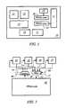
- FIG. 1is a representational block diagram of an integrated circuit with two FPGA cores
- FIG. 2shows a block diagram of a programmable interface for an FPGA core, according to one embodiment of the present invention
- FIG. 3illustrates the control portion of the programmable interface with a circular buffer of latches, according to an embodiment of the present invention
- FIG. 4illustrates the control portion of the programmable interface with programmable shift registers, according to another embodiment of the present invention
- FIG. 5Ashows the details of a rotating shift register which may be used for the FIG. 4 control portion
- FIG. 5Bshows the details of a configurable rotating shift register which might also be used for the FIG. 4 control portion, according to another embodiment of the present invention
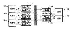
- FIG. 6illustrates an interconnection between FPGA cores and buffer memory blocks with programmable interfaces
- FIG. 7illustrates an interconnection between an FPGA core and an input/output pin with a programmable interface.
- FIG. 1is a representation of an exemplary organization of an ASIC 10 with various functional circuit blocks 11 - 17 interconnected with two FPGA cores 18 and 19 .
- the FPGA core 18is connected to the functional circuit block 16 and core 19 to the functional circuit block 17 .
- the functional circuit blocksmay be a processor unit, memory, specialized function blocks, such as a floating point unit, or even another FPGA core, and the like.
- the particular functions of the blocks 11 - 17 , nor of the cores 18 and 19are undefined. Examples of functional circuit blocks are given below for application examples of the present invention.
- a change in applicationmay render the function of the designed ASIC 10 inadequate or unsatisfactory.
- a reprogramming of the ASIC 10might be considered.
- the FPGA cores 18 and 19may be reconfigured in reprogramming the ASIC 10
- the reconfigured coresmay operate more effectively, or may require, that the core 18 be connected now to the functional circuit block 17 and the core 19 to the functional circuit block 16 , or connected to the other functional circuit blocks. With conventional hard-wired interconnections, such reconnections of the FPGA cores are not possible.
- FIG. 2illustrates an FPGA core 20 with an exemplary programmable interface, according to one embodiment of the present invention.
- an FPGA core 20has an interconnect multiplexer 21 which handles input connections into the core 20 .
- the multiplexer 21is connected to four functional circuit blocks 22 - 25 .
- the multiplexer 21is responsive to control signals on control Select Bit lines 26 and 27 . It should be understood that the connection lines between the functional circuit blocks 22 - 25 and the multiplexer 21 , and between the multiplexer 21 and the FPGA core 20 each represent a plurality of parallel connection lines carrying multiple bits simultaneously.
- the interfacehas an interconnect demultiplexer 28 to handle output connections of the FPGA core 20 to the functional circuit blocks 22 - 25 .
- Control signals on control Select Bit lines 29 and 30 to the demultiplexer 28selects which of the functional circuit blocks 22 - 25 receives the output from the FPGA core 20 .
- control signals to the interconnect multiplexers, demultiplexers being a form of multiplexers, of the FPGA core programmable interfaceare supplied by a programmable control portion of the interface.
- the control bitsare held as Select Bits in programmable latches which are connected to the control signal lines of the interface multiplexers.
- the latchesare loaded during the loading of the configuration bits which set the state of switches in the FPGA logic and interconnection paths.
- the ASICincludes a CPU
- the ASICcan be designed so that the CPU can load the latches with the control Select Bits.
- the configuration bitsprogram one or more of the FPGA cores and the control Select Bits for the programmable interfaces set the connections to and from the FPGA cores.
- FIG. 3illustrates one embodiment of the interface control portion, a circular buffer of four latches 31 A- 31 D which feed into a selection multiplexer 32 controlled by a counter 33 .
- the 2-bit latches 31 A- 31 Din this example hold different combinations of 1's and 0's as control Select Bits.
- the counter 33provides the control signals by which the multiplexer 32 selects the two control bits for an FPGA core interconnect multiplexer 34 .
- the multiplexer 34selects, in this example, the outputs of one of four functional circuit block to connect to the inputs of an FPGA core.
- the multiplexer 34 in a demultiplexer formselects which functional circuit block receives the outputs of an FPGA core.
- the programmable interfaceWith the clocking of the counter 33 , the programmable interface periodically changes the FPGA core interconnections without loading the latches. The FPGA core interconnections are changed dynamically.
- FIG. 4illustrates one example with programmable shift registers 41 and 42 to control the interconnect multiplexers 45 of an FPGA core interface.
- the interconnect multiplexers 45are arrayed in banks which are to be controlled as a single switching unit (e.g., 32 interconnect multiplexers arrayed to select a 32-bit bus), the select control lines 43 and 44 for each interconnect multiplexer 45 in the bank are shared and the controlling programmable shift registers 41 and 42 are likewise shared.
- the interconnect multiplexers 45dynamically reconfigure their connections between functional circuit blocks and FPGA cores.
- An N-configuration programmable shift registercan be programmed with any number of configurations from 1 through N.
- the first configurationis stored in the first latch as control Select Bit 1 of the shift register
- the second configurationis stored in the second latch as control Select Bit 2 of the shift register, and so on.
- each latchWhen a clock line is asserted to the latches of the shift register, each latch changes its stored value to the stored value of the next higher bit latch (e.g., control Select Bit 1 in latch 1 becomes the value of control Select Bit 2 previously held in latch 2 , control Select Bit 2 in latch 2 becomes the value of control Select Bit 3 previously held in latch 3 , and so on).
- the value in the latch of the Most Significant Bit(control Select Bit 8 , for example) becomes the value in the latch of the Least Significant Bit (control Select Bit 1 previously held in latch 1 ).
- the clock linemay be driven by an actual clock signal, or alternatively, it may be asserted by other control logic.
- An 8-configuration programmable shift registeris illustrated in FIG. 5 A.
- NIn the case where fewer than N configurations are to be programmed, modifications to the simple rotating shift register are made. If the number of desired configurations is a factor of N (e.g., 4 desired configurations are a factor of an 8-configuration programmable shift register), the desired configurations are replicated in a serial fashion to fill the programmable shift register.
- the programmable shift registercan be configured so that the Least Significant Bit is fed back into the desired Most Significant Bit (e.g., Bit 3 for 3 desired configurations).
- the programmable shift registeris initialized by setting the contents of each bit in the shift register, and by setting the contents of the internal multiplexer configuration bits to select the desired Most Significant Bit. After initialization, the programmable shift register cycles autonomously whenever its clock line is asserted.
- FIG. 5Billustrates an 8-configuration programmable shift register with internal multiplexers 48 feeding latches for Bit 3 , Bit 5 , Bit 6 and Bit 7 .
- the control selection signals 49 into the multiplexers 48permit selection of the Most Significant Bit and the number of desired configurations.
- a non-autonomous modecan also be supported by using the shift register as a First-In First-Out (FIFO) buffer.
- FIFOFirst-In First-Out
- higher level control logicnot part of this invention, write its required configuration to the MSB (Most Significant Bit) of the shift register.
- the control portion of the programmable interfacecan be provided by an FPGA core which can be programmed as a state machine to provide the control Select Bits to one or more programmable interfaces of other embedded FPGA cores.
- the first FPGA corecan provide dynamic reconfiguration of the programmable interfaces during operation of the integrated circuit and can be reprogrammed when the other FPGA cores are reprogrammed.
- FIGS. 6 and 7Some exemplary applications with the FPGA core programmable interface of the present invention are illustrated in FIGS. 6 and 7 .
- the programmable interfaceare located between FPGA cores and memory, i.e., the functional circuit blocks are in the form of buffer memory blocks such might be found in a wireless or network ASIC.
- the buffer memory blocksare divided as banks 51 and each bank 51 has a single read port 52 and a single write port 53 .
- each FPGA core 54has a single read port in the form of demultiplexer interface 56 and a single write port in the form of a multiplexer interface 55 .
- the actual number of portsare specific to the application.
- the multiplexers of the interfacesare set once during initialization and remain the same throughout the application, though in a CPU-based ASIC, a function to support dynamic scheduling and allocation of the FPGA core-memory bank channels, either under user control at compile time or under automatic control at runtime, should be possible.
- each FPGA corealternates between two memory banks. After an FPGA core has finished processing the data of one memory bank, the core passes that memory bank off to another FPGA core, and then processes the data of a new memory bank passed from the other FPGA core.
- the programmable interfacehas been described with respect to connections between functional circuit blocks and FPGA cores.
- the FPGA core programmable interfacesmay also be used for different connections.
- FPGA coresmight be connected to one or more input/output (IO) pins of an ASIC through programmable interfaces.
- IOinput/output
- FIG. 7the input to an FPGA core 61 is selectably connected by an interface 62 to an IO pin 63 .
- a connection between the FPGA core 61 and a functional circuit block 64is also shown to exemplify the connection of the core to the rest of the integrated circuit.
- the ASIChas a CPU, that unit can make the selection of the pin(s) upon initialization of the integrated circuit and then change the connection to the functional circuit block 64 for operations.
- the CPUcan also control the off-loading of the FPGA core 61 through the pin 63 .
- the pin assignmentare application-specific.
- the programmable interfacehas many applications.
- the programmable interfacemakes the integrated circuits with embedded FPGA cores more flexible in application in a cost-efficient manner.
- the interfaceprovides for features which are not available in integrated circuits with FPGA cores with traditional hard-wired interconnections.
Landscapes
- Engineering & Computer Science (AREA)
- Computer Hardware Design (AREA)
- Theoretical Computer Science (AREA)
- Physics & Mathematics (AREA)
- General Engineering & Computer Science (AREA)
- General Physics & Mathematics (AREA)
- Logic Circuits (AREA)
- Design And Manufacture Of Integrated Circuits (AREA)
Abstract
Description
Claims (24)
Priority Applications (1)
| Application Number | Priority Date | Filing Date | Title |
|---|---|---|---|
| US10/283,019US6888371B2 (en) | 2001-10-29 | 2002-10-29 | Programmable interface for field programmable gate array cores |
Applications Claiming Priority (2)
| Application Number | Priority Date | Filing Date | Title |
|---|---|---|---|
| US34511501P | 2001-10-29 | 2001-10-29 | |
| US10/283,019US6888371B2 (en) | 2001-10-29 | 2002-10-29 | Programmable interface for field programmable gate array cores |
Publications (2)
| Publication Number | Publication Date |
|---|---|
| US20030098710A1 US20030098710A1 (en) | 2003-05-29 |
| US6888371B2true US6888371B2 (en) | 2005-05-03 |
Family
ID=23353592
Family Applications (1)
| Application Number | Title | Priority Date | Filing Date |
|---|---|---|---|
| US10/283,019Expired - Fee RelatedUS6888371B2 (en) | 2001-10-29 | 2002-10-29 | Programmable interface for field programmable gate array cores |
Country Status (4)
| Country | Link |
|---|---|
| US (1) | US6888371B2 (en) |
| EP (1) | EP1440512A1 (en) |
| CN (1) | CN1582533A (en) |
| WO (1) | WO2003039001A1 (en) |
Cited By (4)
| Publication number | Priority date | Publication date | Assignee | Title |
|---|---|---|---|---|
| US20060212838A1 (en)* | 2005-02-09 | 2006-09-21 | Checksum, Llc | System and apparatus for in-system programming |
| US20070024319A1 (en)* | 2003-10-08 | 2007-02-01 | Siemens Aktiengesellschaft | Configurable logic circuit arangement |
| US7725860B1 (en)* | 2000-06-19 | 2010-05-25 | Herman Kwong | Contact mapping using channel routing |
| US8345703B2 (en)* | 2006-10-03 | 2013-01-01 | Alcatel Lucent | Method and apparatus for reconfiguring IC architectures |
Families Citing this family (28)
| Publication number | Priority date | Publication date | Assignee | Title |
|---|---|---|---|---|
| CN100498753C (en)* | 2007-08-31 | 2009-06-10 | 上海广电(集团)有限公司中央研究院 | Method for accessing on-site programmable gate array internal memory through I2C interface |
| US20100138575A1 (en) | 2008-12-01 | 2010-06-03 | Micron Technology, Inc. | Devices, systems, and methods to synchronize simultaneous dma parallel processing of a single data stream by multiple devices |
| CN101452502B (en)* | 2008-12-30 | 2011-04-13 | 华为技术有限公司 | Method for loading on-site programmable gate array FPGA, apparatus and system |
| US20100174887A1 (en) | 2009-01-07 | 2010-07-08 | Micron Technology Inc. | Buses for Pattern-Recognition Processors |
| US9323994B2 (en) | 2009-12-15 | 2016-04-26 | Micron Technology, Inc. | Multi-level hierarchical routing matrices for pattern-recognition processors |
| US8680888B2 (en) | 2011-12-15 | 2014-03-25 | Micron Technologies, Inc. | Methods and systems for routing in a state machine |
| US9443156B2 (en)* | 2011-12-15 | 2016-09-13 | Micron Technology, Inc. | Methods and systems for data analysis in a state machine |
| CN102662686B (en)* | 2012-03-09 | 2015-05-13 | 中国科学院微电子研究所 | FPGA loading method and device |
| US20130275709A1 (en) | 2012-04-12 | 2013-10-17 | Micron Technology, Inc. | Methods for reading data from a storage buffer including delaying activation of a column select |
| US9524248B2 (en) | 2012-07-18 | 2016-12-20 | Micron Technology, Inc. | Memory management for a hierarchical memory system |
| US8656065B1 (en)* | 2013-01-29 | 2014-02-18 | Honeywell International Inc. | Method and apparatus for automatically selecting a plurality of modes for programmable interface circuit by coupling field devices to process controllers |
| US9448965B2 (en) | 2013-03-15 | 2016-09-20 | Micron Technology, Inc. | Receiving data streams in parallel and providing a first portion of data to a first state machine engine and a second portion to a second state machine |
| US9703574B2 (en) | 2013-03-15 | 2017-07-11 | Micron Technology, Inc. | Overflow detection and correction in state machine engines |
| US10523207B2 (en)* | 2014-08-15 | 2019-12-31 | Altera Corporation | Programmable circuit having multiple sectors |
| US11366675B2 (en) | 2014-12-30 | 2022-06-21 | Micron Technology, Inc. | Systems and devices for accessing a state machine |
| US10430210B2 (en) | 2014-12-30 | 2019-10-01 | Micron Technology, Inc. | Systems and devices for accessing a state machine |
| WO2016109571A1 (en) | 2014-12-30 | 2016-07-07 | Micron Technology, Inc | Devices for time division multiplexing of state machine engine signals |
| US10846103B2 (en) | 2015-10-06 | 2020-11-24 | Micron Technology, Inc. | Methods and systems for representing processing resources |
| US10977309B2 (en) | 2015-10-06 | 2021-04-13 | Micron Technology, Inc. | Methods and systems for creating networks |
| US10691964B2 (en) | 2015-10-06 | 2020-06-23 | Micron Technology, Inc. | Methods and systems for event reporting |
| US10146555B2 (en) | 2016-07-21 | 2018-12-04 | Micron Technology, Inc. | Adaptive routing to avoid non-repairable memory and logic defects on automata processor |
| US20180082720A1 (en)* | 2016-09-20 | 2018-03-22 | Altera Corporation | Pipelined interconnect circuitry having reset values holding capabilities |
| US10019311B2 (en) | 2016-09-29 | 2018-07-10 | Micron Technology, Inc. | Validation of a symbol response memory |
| US10268602B2 (en) | 2016-09-29 | 2019-04-23 | Micron Technology, Inc. | System and method for individual addressing |
| US10929764B2 (en) | 2016-10-20 | 2021-02-23 | Micron Technology, Inc. | Boolean satisfiability |
| US10592450B2 (en) | 2016-10-20 | 2020-03-17 | Micron Technology, Inc. | Custom compute cores in integrated circuit devices |
| US12197510B2 (en) | 2016-10-20 | 2025-01-14 | Micron Technology, Inc. | Traversal of S portion of a graph problem to be solved using automata processor |
| CN109902061B (en)* | 2019-02-03 | 2023-06-02 | 旋智电子科技(上海)有限公司 | Digital logic circuit and microprocessor |
Citations (7)
| Publication number | Priority date | Publication date | Assignee | Title |
|---|---|---|---|---|
| US5483178A (en) | 1993-03-29 | 1996-01-09 | Altera Corporation | Programmable logic device with logic block outputs coupled to adjacent logic block output multiplexers |
| US5600264A (en) | 1995-10-16 | 1997-02-04 | Xilinx, Inc. | Programmable single buffered six pass transistor configuration |
| US5889413A (en) | 1996-11-22 | 1999-03-30 | Xilinx, Inc. | Lookup tables which double as shift registers |
| US5905385A (en) | 1997-04-01 | 1999-05-18 | Advanced Micro Devices, Inc. | Memory bits used to couple look up table inputs to facilitate increased availability to routing resources particularly for variable sized look up tables for a field programmable gate array (FPGA) |
| US5960191A (en)* | 1997-05-30 | 1999-09-28 | Quickturn Design Systems, Inc. | Emulation system with time-multiplexed interconnect |
| US6014038A (en)* | 1997-03-21 | 2000-01-11 | Lightspeed Semiconductor Corporation | Function block architecture for gate array |
| US6191612B1 (en)* | 1998-11-19 | 2001-02-20 | Vantis Corporation | Enhanced I/O control flexibility for generating control signals |
Family Cites Families (1)
| Publication number | Priority date | Publication date | Assignee | Title |
|---|---|---|---|---|
| US5483179A (en)* | 1994-04-20 | 1996-01-09 | International Business Machines Corporation | Data output drivers with pull-up devices |
- 2002
- 2002-10-29WOPCT/US2002/034634patent/WO2003039001A1/ennot_activeApplication Discontinuation
- 2002-10-29EPEP02773937Apatent/EP1440512A1/ennot_activeWithdrawn
- 2002-10-29CNCNA028214463Apatent/CN1582533A/enactivePending
- 2002-10-29USUS10/283,019patent/US6888371B2/ennot_activeExpired - Fee Related
Patent Citations (7)
| Publication number | Priority date | Publication date | Assignee | Title |
|---|---|---|---|---|
| US5483178A (en) | 1993-03-29 | 1996-01-09 | Altera Corporation | Programmable logic device with logic block outputs coupled to adjacent logic block output multiplexers |
| US5600264A (en) | 1995-10-16 | 1997-02-04 | Xilinx, Inc. | Programmable single buffered six pass transistor configuration |
| US5889413A (en) | 1996-11-22 | 1999-03-30 | Xilinx, Inc. | Lookup tables which double as shift registers |
| US6014038A (en)* | 1997-03-21 | 2000-01-11 | Lightspeed Semiconductor Corporation | Function block architecture for gate array |
| US5905385A (en) | 1997-04-01 | 1999-05-18 | Advanced Micro Devices, Inc. | Memory bits used to couple look up table inputs to facilitate increased availability to routing resources particularly for variable sized look up tables for a field programmable gate array (FPGA) |
| US5960191A (en)* | 1997-05-30 | 1999-09-28 | Quickturn Design Systems, Inc. | Emulation system with time-multiplexed interconnect |
| US6191612B1 (en)* | 1998-11-19 | 2001-02-20 | Vantis Corporation | Enhanced I/O control flexibility for generating control signals |
Cited By (7)
| Publication number | Priority date | Publication date | Assignee | Title |
|---|---|---|---|---|
| US7725860B1 (en)* | 2000-06-19 | 2010-05-25 | Herman Kwong | Contact mapping using channel routing |
| US20070024319A1 (en)* | 2003-10-08 | 2007-02-01 | Siemens Aktiengesellschaft | Configurable logic circuit arangement |
| US7355439B2 (en)* | 2003-10-08 | 2008-04-08 | Siemens Aktiengesellschaft | Configurable logic circuit arrangement |
| US20060212838A1 (en)* | 2005-02-09 | 2006-09-21 | Checksum, Llc | System and apparatus for in-system programming |
| US20090138841A1 (en)* | 2005-02-09 | 2009-05-28 | Checksum, Llc | System and apparatus for in-system programming |
| US7802021B2 (en) | 2005-02-09 | 2010-09-21 | Checksum, Llc | System and apparatus for in-system programming |
| US8345703B2 (en)* | 2006-10-03 | 2013-01-01 | Alcatel Lucent | Method and apparatus for reconfiguring IC architectures |
Also Published As
| Publication number | Publication date |
|---|---|
| CN1582533A (en) | 2005-02-16 |
| WO2003039001A1 (en) | 2003-05-08 |
| EP1440512A1 (en) | 2004-07-28 |
| US20030098710A1 (en) | 2003-05-29 |
Similar Documents
| Publication | Publication Date | Title |
|---|---|---|
| US6888371B2 (en) | Programmable interface for field programmable gate array cores | |
| US6553479B2 (en) | Local control of multiple context processing elements with major contexts and minor contexts | |
| US7266672B2 (en) | Method and apparatus for retiming in a network of multiple context processing elements | |
| US6108760A (en) | Method and apparatus for position independent reconfiguration in a network of multiple context processing elements | |
| US5552722A (en) | Mask registor for a configurable cellular array | |
| US6434735B1 (en) | Method for programming an FPGA and implementing an FPGA interconnect | |
| US6288566B1 (en) | Configuration state memory for functional blocks on a reconfigurable chip | |
| KR100491662B1 (en) | Enhanced field programmable gate array | |
| US4641276A (en) | Serial-parallel data transfer system for VLSI data paths | |
| US6803785B1 (en) | I/O circuitry shared between processor and programmable logic portions of an integrated circuit | |
| US7088134B1 (en) | Programmable logic device with flexible memory allocation and routing | |
| US7580963B2 (en) | Semiconductor device having an arithmetic unit of a reconfigurable circuit configuration in accordance with stored configuration data and a memory storing fixed value data to be supplied to the arithmetic unit, requiring no data area for storing fixed value data to be set in a configuration memory | |
| US8949576B2 (en) | Arithmetic node including general digital signal processing functions for an adaptive computing machine | |
| JPH10233676A (en) | Method for arraying local mutual connection line inside logic array block and programmable logic circuit | |
| US20040111590A1 (en) | Self-configuring processing element | |
| EP1010088B1 (en) | Scalable memory controller and method therefor | |
| US7908453B2 (en) | Semiconductor device having a dynamically reconfigurable circuit configuration | |
| US7954017B2 (en) | Multiple embedded memories and testing components for the same |
Legal Events
| Date | Code | Title | Description |
|---|---|---|---|
| AS | Assignment | Owner name:LEOPARD LOGIC, INC., CALIFORNIA Free format text:ASSIGNMENT OF ASSIGNORS INTEREST;ASSIGNOR:WONG, DALE;REEL/FRAME:013706/0332 Effective date:20021205 | |
| AS | Assignment | Owner name:AGATE LOGIC, INC., CALIFORNIA Free format text:ASSIGNMENT OF ASSIGNORS INTEREST;ASSIGNOR:LEOPARD LOGIC, INC.;REEL/FRAME:017215/0067 Effective date:20051101 | |
| REMI | Maintenance fee reminder mailed | ||
| REIN | Reinstatement after maintenance fee payment confirmed | ||
| FP | Lapsed due to failure to pay maintenance fee | Effective date:20090503 | |
| FEPP | Fee payment procedure | Free format text:PETITION RELATED TO MAINTENANCE FEES GRANTED (ORIGINAL EVENT CODE: PMFG); ENTITY STATUS OF PATENT OWNER: SMALL ENTITY Free format text:PETITION RELATED TO MAINTENANCE FEES FILED (ORIGINAL EVENT CODE: PMFP); ENTITY STATUS OF PATENT OWNER: SMALL ENTITY | |
| PRDP | Patent reinstated due to the acceptance of a late maintenance fee | Effective date:20100406 | |
| FPAY | Fee payment | Year of fee payment:4 | |
| SULP | Surcharge for late payment | ||
| FPAY | Fee payment | Year of fee payment:8 | |
| REMI | Maintenance fee reminder mailed | ||
| LAPS | Lapse for failure to pay maintenance fees | ||
| STCH | Information on status: patent discontinuation | Free format text:PATENT EXPIRED DUE TO NONPAYMENT OF MAINTENANCE FEES UNDER 37 CFR 1.362 | |
| FP | Lapsed due to failure to pay maintenance fee | Effective date:20170503 |