US6888221B1 - BICMOS technology on SIMOX wafers - Google Patents
BICMOS technology on SIMOX wafersDownload PDFInfo
- Publication number
- US6888221B1 US6888221B1US10/709,114US70911404AUS6888221B1US 6888221 B1US6888221 B1US 6888221B1US 70911404 AUS70911404 AUS 70911404AUS 6888221 B1US6888221 B1US 6888221B1
- Authority
- US
- United States
- Prior art keywords
- base
- single crystalline
- isolation region
- single crystal
- extrinsic base
- Prior art date
- Legal status (The legal status is an assumption and is not a legal conclusion. Google has not performed a legal analysis and makes no representation as to the accuracy of the status listed.)
- Expired - Fee Related
Links
- 238000005516engineering processMethods0.000titledescription7
- 235000012431wafersNutrition0.000titledescription7
- 238000002955isolationMethods0.000claimsabstractdescription104
- 239000000758substrateSubstances0.000claimsabstractdescription78
- 239000013078crystalSubstances0.000claimsabstractdescription68
- 238000000034methodMethods0.000claimsabstractdescription57
- 239000004065semiconductorSubstances0.000claimsabstractdescription40
- 239000012212insulatorSubstances0.000claimsabstractdescription34
- 229910052710siliconInorganic materials0.000claimsabstractdescription10
- 239000010703siliconSubstances0.000claimsabstractdescription10
- VYPSYNLAJGMNEJ-UHFFFAOYSA-NSilicium dioxideChemical compoundO=[Si]=OVYPSYNLAJGMNEJ-UHFFFAOYSA-N0.000claimsdescription33
- 239000000377silicon dioxideSubstances0.000claimsdescription16
- 235000012239silicon dioxideNutrition0.000claimsdescription14
- 230000003647oxidationEffects0.000claimsdescription12
- 238000007254oxidation reactionMethods0.000claimsdescription12
- 238000000151depositionMethods0.000claimsdescription11
- 238000004519manufacturing processMethods0.000claimsdescription11
- 229910052581Si3N4Inorganic materials0.000claimsdescription10
- HQVNEWCFYHHQES-UHFFFAOYSA-Nsilicon nitrideChemical compoundN12[Si]34N5[Si]62N3[Si]51N64HQVNEWCFYHHQES-UHFFFAOYSA-N0.000claimsdescription10
- QVGXLLKOCUKJST-UHFFFAOYSA-Natomic oxygenChemical compound[O]QVGXLLKOCUKJST-UHFFFAOYSA-N0.000claimsdescription9
- 238000005530etchingMethods0.000claimsdescription9
- 229910052760oxygenInorganic materials0.000claimsdescription9
- 239000001301oxygenSubstances0.000claimsdescription9
- 239000007943implantSubstances0.000claimsdescription8
- 125000006850spacer groupChemical group0.000claimsdescription7
- 229910000577Silicon-germaniumInorganic materials0.000description24
- 238000010586diagramMethods0.000description7
- XUIMIQQOPSSXEZ-UHFFFAOYSA-NSiliconChemical compound[Si]XUIMIQQOPSSXEZ-UHFFFAOYSA-N0.000description6
- 238000000206photolithographyMethods0.000description6
- NJPPVKZQTLUDBO-UHFFFAOYSA-NnovaluronChemical compoundC1=C(Cl)C(OC(F)(F)C(OC(F)(F)F)F)=CC=C1NC(=O)NC(=O)C1=C(F)C=CC=C1FNJPPVKZQTLUDBO-UHFFFAOYSA-N0.000description5
- 230000008021depositionEffects0.000description4
- 230000010354integrationEffects0.000description4
- 238000012986modificationMethods0.000description4
- 230000004048modificationEffects0.000description4
- 238000000137annealingMethods0.000description3
- 229910021420polycrystalline siliconInorganic materials0.000description3
- 229920005591polysiliconPolymers0.000description3
- LEVVHYCKPQWKOP-UHFFFAOYSA-N[Si].[Ge]Chemical compound[Si].[Ge]LEVVHYCKPQWKOP-UHFFFAOYSA-N0.000description2
- 230000015572biosynthetic processEffects0.000description2
- 229910052681coesiteInorganic materials0.000description2
- 229910052906cristobaliteInorganic materials0.000description2
- 230000007812deficiencyEffects0.000description2
- 230000000694effectsEffects0.000description2
- 229910044991metal oxideInorganic materials0.000description2
- 150000004706metal oxidesChemical class0.000description2
- 238000001465metallisationMethods0.000description2
- 229910021421monocrystalline siliconInorganic materials0.000description2
- 229920002120photoresistant polymerPolymers0.000description2
- 238000001020plasma etchingMethods0.000description2
- 229910052682stishoviteInorganic materials0.000description2
- 229910052905tridymiteInorganic materials0.000description2
- 229910019142PO4Inorganic materials0.000description1
- OAICVXFJPJFONN-UHFFFAOYSA-NPhosphorusChemical compound[P]OAICVXFJPJFONN-UHFFFAOYSA-N0.000description1
- 239000004614Process AidSubstances0.000description1
- LCSCXSMXSUPMKD-UHFFFAOYSA-K[Si+4].P(=O)([O-])([O-])[O-].[B+3]Chemical compound[Si+4].P(=O)([O-])([O-])[O-].[B+3]LCSCXSMXSUPMKD-UHFFFAOYSA-K0.000description1
- 230000006978adaptationEffects0.000description1
- 230000002411adverseEffects0.000description1
- 238000013459approachMethods0.000description1
- 229910052785arsenicInorganic materials0.000description1
- RQNWIZPPADIBDY-UHFFFAOYSA-Narsenic atomChemical compound[As]RQNWIZPPADIBDY-UHFFFAOYSA-N0.000description1
- 238000003486chemical etchingMethods0.000description1
- 230000002708enhancing effectEffects0.000description1
- 238000000407epitaxyMethods0.000description1
- 238000007429general methodMethods0.000description1
- 239000011521glassSubstances0.000description1
- 238000011065in-situ storageMethods0.000description1
- 238000005468ion implantationMethods0.000description1
- 239000000463materialSubstances0.000description1
- 150000004767nitridesChemical class0.000description1
- 230000001590oxidative effectEffects0.000description1
- NBIIXXVUZAFLBC-UHFFFAOYSA-KphosphateChemical compound[O-]P([O-])([O-])=ONBIIXXVUZAFLBC-UHFFFAOYSA-K0.000description1
- 239000010452phosphateSubstances0.000description1
- 229910052698phosphorusInorganic materials0.000description1
- 239000011574phosphorusSubstances0.000description1
- 238000012545processingMethods0.000description1
- 238000000926separation methodMethods0.000description1
- 229910021332silicideInorganic materials0.000description1
- FVBUAEGBCNSCDD-UHFFFAOYSA-Nsilicide(4-)Chemical compound[Si-4]FVBUAEGBCNSCDD-UHFFFAOYSA-N0.000description1
- 229910052814silicon oxideInorganic materials0.000description1
- 239000000126substanceSubstances0.000description1
Images


Classifications
- H—ELECTRICITY
- H10—SEMICONDUCTOR DEVICES; ELECTRIC SOLID-STATE DEVICES NOT OTHERWISE PROVIDED FOR
- H10D—INORGANIC ELECTRIC SEMICONDUCTOR DEVICES
- H10D10/00—Bipolar junction transistors [BJT]
- H10D10/01—Manufacture or treatment
- H10D10/051—Manufacture or treatment of vertical BJTs
- H10D10/054—Forming extrinsic base regions on silicon substrate after insulating device isolation in vertical BJTs having single crystalline emitter, collector or base regions
- H—ELECTRICITY
- H01—ELECTRIC ELEMENTS
- H01L—SEMICONDUCTOR DEVICES NOT COVERED BY CLASS H10
- H01L21/00—Processes or apparatus adapted for the manufacture or treatment of semiconductor or solid state devices or of parts thereof
- H01L21/70—Manufacture or treatment of devices consisting of a plurality of solid state components formed in or on a common substrate or of parts thereof; Manufacture of integrated circuit devices or of parts thereof
- H01L21/71—Manufacture of specific parts of devices defined in group H01L21/70
- H01L21/76—Making of isolation regions between components
- H01L21/762—Dielectric regions, e.g. EPIC dielectric isolation, LOCOS; Trench refilling techniques, SOI technology, use of channel stoppers
- H01L21/7624—Dielectric regions, e.g. EPIC dielectric isolation, LOCOS; Trench refilling techniques, SOI technology, use of channel stoppers using semiconductor on insulator [SOI] technology
- H01L21/76243—Dielectric regions, e.g. EPIC dielectric isolation, LOCOS; Trench refilling techniques, SOI technology, use of channel stoppers using semiconductor on insulator [SOI] technology using silicon implanted buried insulating layers, e.g. oxide layers, i.e. SIMOX techniques
- H—ELECTRICITY
- H10—SEMICONDUCTOR DEVICES; ELECTRIC SOLID-STATE DEVICES NOT OTHERWISE PROVIDED FOR
- H10D—INORGANIC ELECTRIC SEMICONDUCTOR DEVICES
- H10D10/00—Bipolar junction transistors [BJT]
- H10D10/40—Vertical BJTs
- H—ELECTRICITY
- H10—SEMICONDUCTOR DEVICES; ELECTRIC SOLID-STATE DEVICES NOT OTHERWISE PROVIDED FOR
- H10D—INORGANIC ELECTRIC SEMICONDUCTOR DEVICES
- H10D62/00—Semiconductor bodies, or regions thereof, of devices having potential barriers
- H10D62/10—Shapes, relative sizes or dispositions of the regions of the semiconductor bodies; Shapes of the semiconductor bodies
- H10D62/17—Semiconductor regions connected to electrodes not carrying current to be rectified, amplified or switched, e.g. channel regions
- H10D62/177—Base regions of bipolar transistors, e.g. BJTs or IGBTs
Definitions
- CMOScomplementary metal oxide semiconductor
- HBTheterojunction bipolar
- LTElow temperature epitaxy
- SiGeSilicon Germanium
- STIshallow trench isolation
- Characteristics of these devicesinclude a single-crystalline SiGe intrinsic base and a polycrystalline extrinsic base consisting of polysilicon over the STI region, which renders the resulting NPN (or PNP) geometry non-planar, and in fact quite bumpy.
- NPNor PNP
- transitional faceted regiondisposed in between the intrinsic and extrinsic bases.
- this link regionis highly resistive, which adversely impacts device performance.
- CMOS designersthere remains a big challenge in optimizing the photolithography processes for these devices when the devices are scaled down.
- an embodiment of the inventionprovides a bipolar transistor comprising a patterned isolation region formed below an upper surface of a semiconductor substrate and a single crystal extrinsic base formed on an upper surface of the isolation region.
- the single crystal extrinsic basecomprises a portion of the semiconductor substrate located between the upper surface of the isolation region and the upper surface of the semiconductor substrate.
- the bipolar transistorfurther comprises a single crystal intrinsic base, wherein a portion of the single crystal extrinsic base merges with a portion of the single crystal intrinsic base.
- the isolation regionelectrically isolates the single crystal extrinsic base from a collector.
- the single crystal intrinsic and extrinsic basesseparate the collector from an emitter.
- the single crystal extrinsic basecomprises epitaxially-grown silicon.
- the isolation regioncomprises an insulator, wherein the insulator comprises oxide, and the isolation region comprises any of a shallow trench isolation region and a deep trench isolation region.
- the bipolar transistorfurther comprises a single crystal intrinsic base, wherein a portion of the single crystal extrinsic base merges with a portion of the single crystal intrinsic base, wherein the isolation region electrically isolates the single crystal extrinsic base from the collector, and wherein the single crystal intrinsic and extrinsic bases separate the collector from the emitter.
- the single crystal extrinsic basecomprises epitaxially-grown silicon
- the isolation regioncomprises an insulator, wherein the insulator comprises oxide.
- the isolation regioncomprises any of a shallow trench isolation region and a deep trench isolation region.
- the inventionprovides a method of forming a bipolar transistor, wherein the method comprises forming a patterned isolation region below an upper surface of a semiconductor substrate, forming a single crystal extrinsic base on an upper surface of the isolation region, and forming single crystal intrinsic base over the semiconductor substrate, wherein a portion of the single crystal extrinsic base merges with a portion of the single crystal intrinsic base, and wherein the single crystal extrinsic base comprises a portion of the semiconductor substrate located between the upper surface of the isolation region and the upper surface of the semiconductor substrate.
- the methodfurther comprises converting any polycrystalline portions and a portion of the single crystalline extrinsic base of the bipolar transistor into oxide by performing a high pressure oxidation process over the single crystalline extrinsic base, removing excess portions of the oxide, and forming an oxide isolation layer over the single crystalline extrinsic base by performing a second high pressure oxidation process over the single crystalline extrinsic base, wherein the insulator layers comprise a silicon nitride layer deposited over a silicon dioxide layer.
- the inventionrelates to the state of the art CMOS technologies that are using SOI wafers.
- One main source of SOI wafersare from SIMOX. Building SiGe HBTs on SOI substrates takes advantage of the low power consumption of SOI technology and high current driverability of SiGe HBTs.
- the inventionuses patterned SIMOX for BiCMOS isolation. This enables SiGe HBTs with planar structures.
- the inventionachieves several advantages, such as a new and simple integration scheme that can be used for planar SiGe HBTs.
- the inventionachieves a much improved photolithography process on planar SiGe HBTs, especially as devices are scaled down.
- the inventionallows for reduced effect levels on planar SiGe HBTs and improves device yield.
- CMOSare built at different regions on the same SIMOX wafers thereby providing a simple SiGe SOI technology.
- FIG. 3 ( a )is a schematic diagram showing a cross-sectional segmented view of a device illustrating a third embodiment of the invention
- FIG. 3 ( b )is a schematic diagram showing a cross-sectional segmented view of a device illustrating a fourth embodiment of the invention
- FIGS. 4 ( a ) and 4 ( b )are schematic diagrams showing a cross-sectional segmented view of a geometric configuration of a device according to an embodiment of the invention.
- FIGS. 1 ( a ) through 5 ( d )there are shown preferred embodiments of the invention.
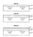
- a bipolar transistoris fabricated beginning with a semiconductor wafer (substrate) 10 as shown in FIG. 1 ( a ).
- the substrate 10is preferably silicon, for example a P-type single crystal (monocrystalline) silicon substrate may be used, however, those skilled in the art would understand that any semiconductor material may be used, and any type of substrate may be used such as a N+ buried layer used to form a subcollector and formed over a semiconductor substrate, and the substrate may be a semiconductor-on-insulator (SOI) substrate.
- SOIsemiconductor-on-insulator
- a typical NPN substrateis formed according to the invention, although a PNP device may also be formed.
- FIG. 1 ( b )illustrates a photoresist layer 15 formed upon the substrate 10 .
- portions of the photoresist layer 15are selectively removed to expose portions of the underlying substrate 10 to allow for a medium dose oxygen implant/high temperature annealing process to occur as depicted in FIG. 1 ( c ) (arrows representing the oxygen implant), which forms a patterned isolation layer 20 underneath the surface of the substrate 10 as further illustrated in FIG. 1 ( d ).
- the patterned isolation layer 20is used as a STI in the NPN region of the substrate 10 , and a BOX (buried oxide layer) in the CMOS region (not shown).
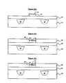
- FIGS. 2 ( a ) and 2 ( b )illustrate an alternative embodiment whereby the patterned isolation layer 120 is used as a deep trench isolation region 12 in one side of the NPN region of the substrate 10 .
- the patterned isolation layer 20 on the other side of the deviceremains as a STI region.
- An advantage of the alternative embodimentincludes reducing collector-to-substrate capacitance, thus enhancing device performances such as f max , unit power gain cut-off frequency.
- FIG. 1 ( e )a LTE SiGe layer 25 is grown over the substrate 10 .
- the LTE SiGe layer 25is monocrystalline throughout and serves as the intrinsic base and portions of the extrinsic base of the device.
- FIGS. 1 ( f ) and 1 ( g )show, respectively, a silicon dioxide pad layer 27 and a silicon nitride or other insulator layer 29 deposited over the SiGe layer 25 .
- photolithography and directional etchingsuch as reactive ion etching is performed over portions of the silicon dioxide layer 27 and silicon nitride layer 29 to define, what shall eventually become the emitter pedestal.
- a second monocrystalline layer 30is deposited over the exposed SiGe layer 25 .
- the layered monocrystalline (merged layers 25 and 30 )serve as the extrinsic base of the bipolar transistor, which controls conduction of electron injunction from the emitter 40 to the collector 60 to the sub-collector 50 (further shown in FIG. 1 ( r )).
- a polycrystalline polysilicon layer 29is deposited over the silicon nitride layer 31 as shown in FIG. 1 ( j ).
- the polycrystalline layer 29is deposited at a much slower rate than the second monocrystalline layer 30 .
- the polycrystalline layer 29is thinner than the second monocrystalline layer 30 .
- the deposition rate of the second mono-crystalline layer 30is 3 nm/min, while the deposition rate of the poly-crystalline layer 29 is 0.3 nm/min.
- the thickness of layer 30is 100 nm, while layer 29 is 10 nm.
- the growth of the polycrystalline layer 29is an inevitable because the growth starts from SiN or SiO 2 which is not single crystalline.
- FIG. 1 ( k )HIPOX (High Pressure Oxidation) is performed whereby layer 32 is the silicon oxide layer that is converted from the polysilicon film 29 over the emitter.
- thermal oxidationis carried out at the pressure of oxidizing ambient significantly higher than atmospheric pressure (e.g. 25 atm.), which allows fast growth of an oxide at reduced temperature.
- the oxide layer 32is removed as shown in FIG. 1 ( l ).
- FIG. 1 ( m )illustrates a second HIPOX layer 33 is converted from part of layer 30 outside the emitter pedestal region of emitter-base isolation. Thus, oxide 33 remains over the second monocrystalline layer 30 .
- a hot phosphate processis performed to remove the nitride layer 29 in the emitter pedestal as shown in FIG. 1 ( n ). This process aids in providing a self-aligned emitter opening.
- a pair of nitride spacers 35is formed on opposite sides of the emitter pedestal to further provide emitter-base isolation. The spacers 35 are formed over the silicon dioxide layer 27 and along the side walls of the oxide layer 33 and a portion of the second monocrystalline layer 33 .
- FIG. 1 ( p )the exposed silicon dioxide layer 27 unprotected by the nitride spacers 35 are removed by a chemical oxide removal process to provide a pre-emitter clean.
- FIG. 1 ( q ) in -situ doped emitter depositionoccurs by depositing arsenic or phosphorus to serve as the emitter 40 of the bipolar transistor.
- BiCMOS processinvolves well-known processes such as chemical etching, photolithography and etching to define the base regions 25 , 30 of the bipolar n-p-n devices, silicide formation at the base 25 , 30 and collector 60 regions, boron phosphate silicon glass (BPSG) pre-metallization layer deposition, CMP planarization of the BPSG film, contact formation in the BPSG film, and back-end-of-line metallization.
- BPSGboron phosphate silicon glass
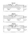
- FIGS. 3 ( a ) and 3 ( b )illustrate various types of collector integration embodiments according to the invention.
- the collector integrationincludes the entire bipolar area including underneath the isolation region 20 , and further includes a sub-collector.
- This embodimentsimplifies the conventionally used low-energy implanted sub-collector followed by n-epi growth process. Moreover, this embodiment can be either enabled before or after the SIMOX I/I (ion implantation) annealing process.
- a pedestal collectoris formed, and is preferably performed prior to the SiGe LTE growth (which is shown in FIG. 1 ( e )) and/or after the emitter opening etch (shown in FIG. 1 ( o )).
- FIG. 3 ( a )shows a deep implanted collector and FIG. 3 ( b ) illustrates a collector implanted into a smaller area prior to the SIMOX I/I annealing process.
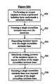
- FIG. 5 ( b )A more detailed description of the method of manufacturing a bipolar transistor is illustrated in FIG. 5 ( b ), wherein the method comprises performing 520 an oxygen implant to form a patterned isolation layer 20 underneath a substrate surface 10 , forming 522 a single crystalline intrinsic base 25 over the substrate 10 , depositing 524 insulator layers 27 , 29 over the single crystalline intrinsic base 25 , selectively etching 526 portions of the insulator layers 27 , 29 to expose portions of the single transistor crystalline intrinsic base 25 , and forming 528 a single crystalline extrinsic base 30 over exposed portions of the single crystalline intrinsic base 25 .
- the methodfurther comprises converting 540 any polycrystalline portions and a portion of the single crystalline extrinsic base 30 of the bipolar transistor into oxide 32 by performing a high pressure oxidation process over the single crystalline extrinsic base 30 , removing 542 excess portions of the oxide 32 , and forming 544 an oxide isolation layer 33 over the single crystalline extrinsic base 30 by performing a second high pressure oxidation process over the single crystalline extrinsic base 30 , wherein the insulator layers 27 , 29 comprise a silicon nitride layer 29 deposited over a silicon dioxide layer 27 .
- the methodfurther comprises removing 550 remaining portions of the silicon nitride layer 29 , forming 552 a pair of isolation spacers 35 adjacent a sidewall of the single crystalline extrinsic base 30 and the oxide isolation layer 33 and over the silicon dioxide layer 27 , removing 554 exposed portions of the silicon dioxide layer 27 unprotected by the isolation spacers 35 thereby exposing the single crystalline intrinsic base 25 , and defining 556 an emitter region 40 over the single crystalline intrinsic base 25 , wherein the single crystalline extrinsic base 30 comprises a portion (D 1 ) of the substrate 10 located between an upper surface of the patterned isolation layer 20 and an upper surface of the substrate 10 , and wherein a portion of the single crystalline extrinsic base 30 merges with a portion of the single crystalline intrinsic base 25 , which further defines the intrinsic base 70 in the bipolar transistor.
- the inventionuses patterned SIMOX for BiCMOS isolation. This enables SiGe HBTs with planar structures.
- the inventionachieves several advantages, such as a new and simple integration scheme that can be used for planar SiGe HBTs. Also, the invention achieves a much improved photolithography process on planar SiGe HBTs, especially as devices are scaled down. Moreover, the invention allows for reduced effect levels on planar SiGe HBTs and improves device yield.
- CMOSare built at different regions on the same SIMOX wafers thereby providing a simple SiGe SOI technology.
- the inventionprovides a bipolar transistor comprising an isolation region 20 formed below an upper surface of a semiconductor substrate 10 and a single crystal extrinsic base 30 formed on an upper surface of the isolation region 20 .
- the single crystal extrinsic base 30comprises a portion (D 1 ) of the semiconductor substrate 10 located between the upper surface of the isolation region 20 and the upper surface of the semiconductor substrate 10 .
- the bipolar transistorfurther comprises a single crystal intrinsic base 25 , wherein a portion of the single crystal extrinsic base 30 merges with a portion of the single crystal intrinsic base 25 , which further defines the single crystal intrinsic base region 70 of the bipolar transistor.
- the merged extrinsic base region(region 25 and 30 on the periphery of the intrinsic base region 70 ) help distinguish between the intrinsic base region 70 and the merged extrinsic base region (regions 25 and 30 ) located on opposite sides of the intrinsic base region 70 .
- the merged area of the extrinsic base regionis illustrated in the dotted area 80 .
- the isolation region 20electrically isolates the single crystal extrinsic base 25 from a collector 60 .
- the single crystal intrinsic and extrinsic 25 , 30 basesseparate the collector 60 from an emitter 40 .
- the single crystal extrinsic base 30comprises epitaxially-grown silicon or silicon germanium or any other combination of there two layers.
- the isolation region 20comprises an insulator, wherein the insulator comprises oxide, and the isolation region 20 comprises any of a shallow trench isolation region and a deep trench isolation region.
- the bipolar transistorcomprises a semiconductor substrate 10 , a sub-collector 50 in the semiconductor substrate 10 , a collector 60 adjacent the sub-collector 50 , an isolation region 20 encapsulated within the semiconductor substrate 10 , a single crystal extrinsic base 30 over the isolation region 20 , and an emitter 40 adjacent the single crystal extrinsic base 30 .
- the inventionprovides a single crystalline extrinsic base (merged region 80 ), contrary to a polycrystalline extrinsic base found in conventional devices. More specifically, the single crystalline is extended to directly underneath the base contacts. As such, the invention provides a resulting planar geometry of the device. Also, because there is no transitional faceted region disposed in between the intrinsic and extrinsic bases 25 , 30 , the device performance is improved compared to the conventional devices.
Landscapes
- Engineering & Computer Science (AREA)
- Physics & Mathematics (AREA)
- Condensed Matter Physics & Semiconductors (AREA)
- General Physics & Mathematics (AREA)
- Manufacturing & Machinery (AREA)
- Computer Hardware Design (AREA)
- Microelectronics & Electronic Packaging (AREA)
- Power Engineering (AREA)
- Bipolar Transistors (AREA)
Abstract
Description
Claims (30)
Priority Applications (1)
| Application Number | Priority Date | Filing Date | Title |
|---|---|---|---|
| US10/709,114US6888221B1 (en) | 2004-04-14 | 2004-04-14 | BICMOS technology on SIMOX wafers |
Applications Claiming Priority (1)
| Application Number | Priority Date | Filing Date | Title |
|---|---|---|---|
| US10/709,114US6888221B1 (en) | 2004-04-14 | 2004-04-14 | BICMOS technology on SIMOX wafers |
Publications (1)
| Publication Number | Publication Date |
|---|---|
| US6888221B1true US6888221B1 (en) | 2005-05-03 |
Family
ID=34522967
Family Applications (1)
| Application Number | Title | Priority Date | Filing Date |
|---|---|---|---|
| US10/709,114Expired - Fee RelatedUS6888221B1 (en) | 2004-04-14 | 2004-04-14 | BICMOS technology on SIMOX wafers |
Country Status (1)
| Country | Link |
|---|---|
| US (1) | US6888221B1 (en) |
Cited By (16)
| Publication number | Priority date | Publication date | Assignee | Title |
|---|---|---|---|---|
| US20040235256A1 (en)* | 2001-08-28 | 2004-11-25 | Chihiro Arai | Semiconductor device and method for manufacturing the same |
| US20050164454A1 (en)* | 2004-01-27 | 2005-07-28 | Micron Technology, Inc. | Selective epitaxy vertical integrated circuit components and methods |
| US20060060886A1 (en)* | 2004-09-21 | 2006-03-23 | International Business Machines Corporation | METHOD TO BUILD SELF-ALIGNED NPN IN ADVANCED BiCMOS TECHNOLOGY |
| US20070275510A1 (en)* | 2006-05-25 | 2007-11-29 | International Business Machines Corporation | Metal oxide field effect transistor with a sharp halo and a method of forming the transistor |
| US20070298578A1 (en)* | 2006-06-21 | 2007-12-27 | International Business Machines Corporation | Bipolar transistor with dual shallow trench isolation and low base resistance |
| US20080121930A1 (en)* | 2006-11-08 | 2008-05-29 | International Business Machines Corporation | Monocrystalline extrinsic base and emitter heterojunction bipolar transistor and related methods |
| US20090020851A1 (en)* | 2006-12-21 | 2009-01-22 | International Business Machines Corporation (''ibm") | Bicmos devices with a self-aligned emitter and methods of fabricating such bicmos devices |
| US20100038744A1 (en)* | 2008-08-15 | 2010-02-18 | Qualcomm Incorporated | Shallow Trench Isolation |
| US7863133B2 (en) | 2005-06-28 | 2011-01-04 | Micron Technology, Inc. | Oxide epitaxial isolation |
| US8536012B2 (en) | 2011-07-06 | 2013-09-17 | International Business Machines Corporation | Bipolar junction transistors with a link region connecting the intrinsic and extrinsic bases |
| US8786051B2 (en) | 2012-02-21 | 2014-07-22 | International Business Machines Corporation | Transistor having a monocrystalline center section and a polycrystalline outer section, and narrow in-substrate collector region for reduced base-collector junction capacitance |
| US8796149B1 (en) | 2013-02-18 | 2014-08-05 | International Business Machines Corporation | Collector-up bipolar junction transistors in BiCMOS technology |
| US8816401B2 (en)* | 2012-11-30 | 2014-08-26 | International Business Machines Corporation | Heterojunction bipolar transistor |
| US8956945B2 (en) | 2013-02-04 | 2015-02-17 | International Business Machines Corporation | Trench isolation for bipolar junction transistors in BiCMOS technology |
| US9029229B2 (en) | 2013-05-29 | 2015-05-12 | International Business Machines Corporation | Semiconductor device and method of forming the device by forming monocrystalline semiconductor layers on a dielectric layer over isolation regions |
| US9093491B2 (en) | 2012-12-05 | 2015-07-28 | International Business Machines Corporation | Bipolar junction transistors with reduced base-collector junction capacitance |
Citations (9)
| Publication number | Priority date | Publication date | Assignee | Title |
|---|---|---|---|---|
| US4997776A (en) | 1989-03-06 | 1991-03-05 | International Business Machines Corp. | Complementary bipolar transistor structure and method for manufacture |
| US5118634A (en) | 1990-09-26 | 1992-06-02 | Purdue Research Foundation | Self-aligned integrated circuit bipolar transistor having monocrystalline contacts |
| US5698890A (en) | 1994-09-12 | 1997-12-16 | Nec Corporation | Semiconductor device having bipolar transistor free from leakage current across thin base region |
| US6441462B1 (en)* | 2001-07-10 | 2002-08-27 | International Business Machines Corporation | Self-aligned SiGe NPN with improved ESD robustness using wide emitter polysilicon extension |
| US6486532B1 (en) | 2000-09-30 | 2002-11-26 | Newport Fab, Llc | Structure for reduction of base and emitter resistance and related method |
| US20020177253A1 (en) | 2001-05-25 | 2002-11-28 | International Business Machines Corporation | Process for making a high voltage NPN Bipolar device with improved AC performance |
| US6521974B1 (en)* | 1999-10-14 | 2003-02-18 | Hitachi, Ltd. | Bipolar transistor and manufacturing method thereof |
| US20030094673A1 (en) | 2001-11-16 | 2003-05-22 | International Business Machines Corporation | Semiconductor device and method having multiple subcollectors formed on a common wafer |
| US20030098465A1 (en) | 2001-11-29 | 2003-05-29 | Hitachi, Ltd. | Heterojunction bipolar transistor and method for production thereof |
- 2004
- 2004-04-14USUS10/709,114patent/US6888221B1/ennot_activeExpired - Fee Related
Patent Citations (9)
| Publication number | Priority date | Publication date | Assignee | Title |
|---|---|---|---|---|
| US4997776A (en) | 1989-03-06 | 1991-03-05 | International Business Machines Corp. | Complementary bipolar transistor structure and method for manufacture |
| US5118634A (en) | 1990-09-26 | 1992-06-02 | Purdue Research Foundation | Self-aligned integrated circuit bipolar transistor having monocrystalline contacts |
| US5698890A (en) | 1994-09-12 | 1997-12-16 | Nec Corporation | Semiconductor device having bipolar transistor free from leakage current across thin base region |
| US6521974B1 (en)* | 1999-10-14 | 2003-02-18 | Hitachi, Ltd. | Bipolar transistor and manufacturing method thereof |
| US6486532B1 (en) | 2000-09-30 | 2002-11-26 | Newport Fab, Llc | Structure for reduction of base and emitter resistance and related method |
| US20020177253A1 (en) | 2001-05-25 | 2002-11-28 | International Business Machines Corporation | Process for making a high voltage NPN Bipolar device with improved AC performance |
| US6441462B1 (en)* | 2001-07-10 | 2002-08-27 | International Business Machines Corporation | Self-aligned SiGe NPN with improved ESD robustness using wide emitter polysilicon extension |
| US20030094673A1 (en) | 2001-11-16 | 2003-05-22 | International Business Machines Corporation | Semiconductor device and method having multiple subcollectors formed on a common wafer |
| US20030098465A1 (en) | 2001-11-29 | 2003-05-29 | Hitachi, Ltd. | Heterojunction bipolar transistor and method for production thereof |
Cited By (37)
| Publication number | Priority date | Publication date | Assignee | Title |
|---|---|---|---|---|
| US20060097351A1 (en)* | 2001-08-28 | 2006-05-11 | Sony Corporation | Semiconductor device and method for manufacturing the same |
| US7064417B2 (en)* | 2001-08-28 | 2006-06-20 | Sony Corporation | Semiconductor device including a bipolar transistor |
| US7271046B2 (en) | 2001-08-28 | 2007-09-18 | Sony Corporation | Method of making a semiconductor device in which a bipolar transistor and a metal silicide layer are formed on a substrate |
| US20040235256A1 (en)* | 2001-08-28 | 2004-11-25 | Chihiro Arai | Semiconductor device and method for manufacturing the same |
| US7851309B2 (en) | 2004-01-27 | 2010-12-14 | Micron Technology, Inc. | Selective epitaxy vertical integrated circuit components and methods |
| US20050164454A1 (en)* | 2004-01-27 | 2005-07-28 | Micron Technology, Inc. | Selective epitaxy vertical integrated circuit components and methods |
| US20060006444A1 (en)* | 2004-01-27 | 2006-01-12 | Micron Technology, Inc. | Selective epitaxy vertical integrated circuit components and methods |
| US7514324B2 (en) | 2004-01-27 | 2009-04-07 | Micron Technology, Inc. | Selective epitaxy in vertical integrated circuit |
| US20090197379A1 (en)* | 2004-01-27 | 2009-08-06 | Leslie Terrence C | Selective epitaxy vertical integrated circuit components and methods |
| US7372091B2 (en) | 2004-01-27 | 2008-05-13 | Micron Technology, Inc. | Selective epitaxy vertical integrated circuit components |
| US20060060886A1 (en)* | 2004-09-21 | 2006-03-23 | International Business Machines Corporation | METHOD TO BUILD SELF-ALIGNED NPN IN ADVANCED BiCMOS TECHNOLOGY |
| US20070264787A1 (en)* | 2004-09-21 | 2007-11-15 | International Business Machines Corporation | METHOD TO BUILD SELF-ALIGNED NPN IN ADVANCED BiCMOS TECHNOLOGY |
| US7776704B2 (en) | 2004-09-21 | 2010-08-17 | International Business Machines Corporation | Method to build self-aligned NPN in advanced BiCMOS technology |
| US7265018B2 (en)* | 2004-09-21 | 2007-09-04 | International Business Machines Corporation | Method to build self-aligned NPN in advanced BiCMOS technology |
| US7863133B2 (en) | 2005-06-28 | 2011-01-04 | Micron Technology, Inc. | Oxide epitaxial isolation |
| US20070275510A1 (en)* | 2006-05-25 | 2007-11-29 | International Business Machines Corporation | Metal oxide field effect transistor with a sharp halo and a method of forming the transistor |
| US7384835B2 (en) | 2006-05-25 | 2008-06-10 | International Business Machines Corporation | Metal oxide field effect transistor with a sharp halo and a method of forming the transistor |
| US20080093629A1 (en)* | 2006-05-25 | 2008-04-24 | International Business Machines Corporation | Metal oxide field effect transistor with a sharp halo |
| US7859013B2 (en) | 2006-05-25 | 2010-12-28 | International Business Machines Corporation | Metal oxide field effect transistor with a sharp halo |
| US7888745B2 (en) | 2006-06-21 | 2011-02-15 | International Business Machines Corporation | Bipolar transistor with dual shallow trench isolation and low base resistance |
| US20070298578A1 (en)* | 2006-06-21 | 2007-12-27 | International Business Machines Corporation | Bipolar transistor with dual shallow trench isolation and low base resistance |
| US7521772B2 (en)* | 2006-11-08 | 2009-04-21 | International Business Machines Corporation | Monocrystalline extrinsic base and emitter heterojunction bipolar transistor and related methods |
| US20080121930A1 (en)* | 2006-11-08 | 2008-05-29 | International Business Machines Corporation | Monocrystalline extrinsic base and emitter heterojunction bipolar transistor and related methods |
| US20090020851A1 (en)* | 2006-12-21 | 2009-01-22 | International Business Machines Corporation (''ibm") | Bicmos devices with a self-aligned emitter and methods of fabricating such bicmos devices |
| US7709338B2 (en) | 2006-12-21 | 2010-05-04 | International Business Machines Corporation | BiCMOS devices with a self-aligned emitter and methods of fabricating such BiCMOS devices |
| US7998815B2 (en)* | 2008-08-15 | 2011-08-16 | Qualcomm Incorporated | Shallow trench isolation |
| US20100038744A1 (en)* | 2008-08-15 | 2010-02-18 | Qualcomm Incorporated | Shallow Trench Isolation |
| US8536012B2 (en) | 2011-07-06 | 2013-09-17 | International Business Machines Corporation | Bipolar junction transistors with a link region connecting the intrinsic and extrinsic bases |
| US8716837B2 (en) | 2011-07-06 | 2014-05-06 | International Business Machines Corporation | Bipolar junction transistors with a link region connecting the intrinsic and extrinsic bases |
| US8786051B2 (en) | 2012-02-21 | 2014-07-22 | International Business Machines Corporation | Transistor having a monocrystalline center section and a polycrystalline outer section, and narrow in-substrate collector region for reduced base-collector junction capacitance |
| US8816401B2 (en)* | 2012-11-30 | 2014-08-26 | International Business Machines Corporation | Heterojunction bipolar transistor |
| US9093491B2 (en) | 2012-12-05 | 2015-07-28 | International Business Machines Corporation | Bipolar junction transistors with reduced base-collector junction capacitance |
| US9240448B2 (en) | 2012-12-05 | 2016-01-19 | Globalfoundries Inc. | Bipolar junction transistors with reduced base-collector junction capacitance |
| US8956945B2 (en) | 2013-02-04 | 2015-02-17 | International Business Machines Corporation | Trench isolation for bipolar junction transistors in BiCMOS technology |
| US9337323B2 (en) | 2013-02-04 | 2016-05-10 | Globalfoundries Inc. | Trench isolation for bipolar junction transistors in BiCMOS technology |
| US8796149B1 (en) | 2013-02-18 | 2014-08-05 | International Business Machines Corporation | Collector-up bipolar junction transistors in BiCMOS technology |
| US9029229B2 (en) | 2013-05-29 | 2015-05-12 | International Business Machines Corporation | Semiconductor device and method of forming the device by forming monocrystalline semiconductor layers on a dielectric layer over isolation regions |
Similar Documents
| Publication | Publication Date | Title |
|---|---|---|
| US10374069B2 (en) | Bipolar transistor and method of manufacturing the same | |
| US8048734B2 (en) | Bipolar transistor and method for making same | |
| US9508824B2 (en) | Method for fabricating a bipolar transistor having self-aligned emitter contact | |
| US8420493B2 (en) | SOI SiGe-base lateral bipolar junction transistor | |
| US6979884B2 (en) | Bipolar transistor having self-aligned silicide and a self-aligned emitter contact border | |
| JP4398394B2 (en) | Bipolar transistor manufacturing method | |
| US6972443B2 (en) | Structure and method of forming a bipolar transistor having a self-aligned raised extrinsic base using link-up region formed from an opening therein | |
| US10468508B2 (en) | Heterojunction bipolar transistor and method of manufacturing the same | |
| US6888221B1 (en) | BICMOS technology on SIMOX wafers | |
| US9076835B2 (en) | Vertically base-connected bipolar transistor | |
| US20050079678A1 (en) | Heterojunction bipolar transistor using reverse emitter window | |
| CN101410959A (en) | Bipolar transistor with dual shallow trench isolation and low base resistance | |
| JPH07335663A (en) | Vertical heterojunction bipolar transistor and method of manufacturing the same | |
| US5962879A (en) | Super self-aligned bipolar transistor | |
| US6927476B2 (en) | Bipolar device having shallow junction raised extrinsic base and method for making the same | |
| US7442595B2 (en) | Bipolar transistor with collector having an epitaxial Si:C region | |
| US7935606B2 (en) | Transistor manufacture | |
| US10134880B2 (en) | Self-aligned bipolar junction transistors with a base grown in a dielectric cavity | |
| JPH07254611A (en) | Semiconductor device and manufacturing method thereof | |
| US7511317B2 (en) | Porous silicon for isolation region formation and related structure | |
| US6531720B2 (en) | Dual sidewall spacer for a self-aligned extrinsic base in SiGe heterojunction bipolar transistors | |
| US7226844B2 (en) | Method of manufacturing a bipolar transistor with a single-crystal base contact | |
| JP2613029B2 (en) | Manufacturing method of super self-aligned vertical structure bipolar transistor | |
| JP2613031B2 (en) | Manufacturing method of bipolar transistor | |
| US10529836B1 (en) | SiGe heterojunction bipolar transistor with crystalline raised base on germanium etch stop layer |
Legal Events
| Date | Code | Title | Description |
|---|---|---|---|
| AS | Assignment | Owner name:INTERNATIONAL BUSINESS MACHINES CORPORATION, NEW Y Free format text:ASSIGNMENT OF ASSIGNORS INTEREST;ASSIGNORS:JOSEPH, ALVIN J;LIU, QIZHI;SADANA, DEVENDRA K.;REEL/FRAME:014502/0242;SIGNING DATES FROM 20040405 TO 20040414 | |
| FEPP | Fee payment procedure | Free format text:PAYOR NUMBER ASSIGNED (ORIGINAL EVENT CODE: ASPN); ENTITY STATUS OF PATENT OWNER: LARGE ENTITY | |
| FPAY | Fee payment | Year of fee payment:4 | |
| REMI | Maintenance fee reminder mailed | ||
| FPAY | Fee payment | Year of fee payment:8 | |
| SULP | Surcharge for late payment | Year of fee payment:7 | |
| AS | Assignment | Owner name:GLOBALFOUNDRIES U.S. 2 LLC, NEW YORK Free format text:ASSIGNMENT OF ASSIGNORS INTEREST;ASSIGNOR:INTERNATIONAL BUSINESS MACHINES CORPORATION;REEL/FRAME:036550/0001 Effective date:20150629 | |
| AS | Assignment | Owner name:GLOBALFOUNDRIES INC., CAYMAN ISLANDS Free format text:ASSIGNMENT OF ASSIGNORS INTEREST;ASSIGNORS:GLOBALFOUNDRIES U.S. 2 LLC;GLOBALFOUNDRIES U.S. INC.;REEL/FRAME:036779/0001 Effective date:20150910 | |
| REMI | Maintenance fee reminder mailed | ||
| LAPS | Lapse for failure to pay maintenance fees | ||
| STCH | Information on status: patent discontinuation | Free format text:PATENT EXPIRED DUE TO NONPAYMENT OF MAINTENANCE FEES UNDER 37 CFR 1.362 | |
| FP | Lapsed due to failure to pay maintenance fee | Effective date:20170503 | |
| AS | Assignment | Owner name:GLOBALFOUNDRIES U.S. INC., NEW YORK Free format text:RELEASE BY SECURED PARTY;ASSIGNOR:WILMINGTON TRUST, NATIONAL ASSOCIATION;REEL/FRAME:056987/0001 Effective date:20201117 |