US6887234B2 - Cryogenic catheter system - Google Patents
Cryogenic catheter systemDownload PDFInfo
- Publication number
- US6887234B2 US6887234B2US10/252,501US25250102AUS6887234B2US 6887234 B2US6887234 B2US 6887234B2US 25250102 AUS25250102 AUS 25250102AUS 6887234 B2US6887234 B2US 6887234B2
- Authority
- US
- United States
- Prior art keywords
- catheter
- pressure
- injection
- console
- fluid coolant
- Prior art date
- Legal status (The legal status is an assumption and is not a legal conclusion. Google has not performed a legal analysis and makes no representation as to the accuracy of the status listed.)
- Expired - Lifetime, expires
Links
- 239000012530fluidSubstances0.000claimsabstractdescription23
- 238000011282treatmentMethods0.000claimsabstractdescription13
- 238000000034methodMethods0.000claimsdescription62
- 239000002826coolantSubstances0.000claimsdescription51
- 239000008280bloodSubstances0.000claimsdescription16
- 210000004369bloodAnatomy0.000claimsdescription16
- 238000001514detection methodMethods0.000claimsdescription15
- 238000012544monitoring processMethods0.000claimsdescription9
- 230000001276controlling effectEffects0.000claims11
- 230000013011matingEffects0.000claims10
- 230000001105regulatory effectEffects0.000claims6
- 238000002347injectionMethods0.000description103
- 239000007924injectionSubstances0.000description103
- 239000003507refrigerantSubstances0.000description62
- 238000011084recoveryMethods0.000description25
- 210000001519tissueAnatomy0.000description19
- 239000007788liquidSubstances0.000description16
- 238000002679ablationMethods0.000description11
- 238000013507mappingMethods0.000description10
- 238000012360testing methodMethods0.000description9
- 230000000747cardiac effectEffects0.000description8
- 238000010586diagramMethods0.000description7
- 230000003902lesionEffects0.000description7
- 238000005057refrigerationMethods0.000description6
- 238000001816coolingMethods0.000description5
- 238000012423maintenanceMethods0.000description5
- 230000008569processEffects0.000description5
- 230000002159abnormal effectEffects0.000description4
- 230000009471actionEffects0.000description4
- 230000001010compromised effectEffects0.000description4
- 238000009428plumbingMethods0.000description4
- 230000005236sound signalEffects0.000description4
- 206010003119arrhythmiaDiseases0.000description3
- 210000004027cellAnatomy0.000description3
- 230000008859changeEffects0.000description3
- 230000006378damageEffects0.000description3
- 230000037361pathwayEffects0.000description3
- 238000012545processingMethods0.000description3
- 206010003658Atrial FibrillationDiseases0.000description2
- 206010003662Atrial flutterDiseases0.000description2
- 230000005856abnormalityEffects0.000description2
- 230000003126arrythmogenic effectEffects0.000description2
- 230000008901benefitEffects0.000description2
- 238000004891communicationMethods0.000description2
- 230000003247decreasing effectEffects0.000description2
- 230000000694effectsEffects0.000description2
- 238000001595flow curveMethods0.000description2
- 210000005003heart tissueAnatomy0.000description2
- 238000003825pressingMethods0.000description2
- 238000005086pumpingMethods0.000description2
- 238000013024troubleshootingMethods0.000description2
- 230000000007visual effectEffects0.000description2
- 208000001871TachycardiaDiseases0.000description1
- 230000006793arrhythmiaEffects0.000description1
- 230000004888barrier functionEffects0.000description1
- 238000010009beatingMethods0.000description1
- 230000015572biosynthetic processEffects0.000description1
- 238000009529body temperature measurementMethods0.000description1
- 230000007012clinical effectEffects0.000description1
- 230000003750conditioning effectEffects0.000description1
- 238000012790confirmationMethods0.000description1
- 231100001261hazardousToxicity0.000description1
- 210000002064heart cellAnatomy0.000description1
- 230000001788irregularEffects0.000description1
- 238000002955isolationMethods0.000description1
- 230000007257malfunctionEffects0.000description1
- 238000002324minimally invasive surgeryMethods0.000description1
- 230000003287optical effectEffects0.000description1
- 238000011369optimal treatmentMethods0.000description1
- 230000002093peripheral effectEffects0.000description1
- 238000011897real-time detectionMethods0.000description1
- 238000011160researchMethods0.000description1
- 230000001954sterilising effectEffects0.000description1
- 238000004659sterilization and disinfectionMethods0.000description1
- 238000001356surgical procedureMethods0.000description1
- 230000026676system processEffects0.000description1
- 230000006794tachycardiaEffects0.000description1
- 230000001225therapeutic effectEffects0.000description1
- 230000002792vascularEffects0.000description1
- 210000005166vasculatureAnatomy0.000description1
- 238000013022ventingMethods0.000description1
- 206010047302ventricular tachycardiaDiseases0.000description1
Images


Classifications
- A—HUMAN NECESSITIES
- A61—MEDICAL OR VETERINARY SCIENCE; HYGIENE
- A61B—DIAGNOSIS; SURGERY; IDENTIFICATION
- A61B18/00—Surgical instruments, devices or methods for transferring non-mechanical forms of energy to or from the body
- A61B18/02—Surgical instruments, devices or methods for transferring non-mechanical forms of energy to or from the body by cooling, e.g. cryogenic techniques
- A—HUMAN NECESSITIES
- A61—MEDICAL OR VETERINARY SCIENCE; HYGIENE
- A61B—DIAGNOSIS; SURGERY; IDENTIFICATION
- A61B17/00—Surgical instruments, devices or methods
- A61B2017/00017—Electrical control of surgical instruments
- A61B2017/00022—Sensing or detecting at the treatment site
- A61B2017/00084—Temperature
- A61B2017/00092—Temperature using thermocouples
- A—HUMAN NECESSITIES
- A61—MEDICAL OR VETERINARY SCIENCE; HYGIENE
- A61B—DIAGNOSIS; SURGERY; IDENTIFICATION
- A61B17/00—Surgical instruments, devices or methods
- A61B2017/00017—Electrical control of surgical instruments
- A61B2017/00115—Electrical control of surgical instruments with audible or visual output
- A61B2017/00119—Electrical control of surgical instruments with audible or visual output alarm; indicating an abnormal situation
- A—HUMAN NECESSITIES
- A61—MEDICAL OR VETERINARY SCIENCE; HYGIENE
- A61B—DIAGNOSIS; SURGERY; IDENTIFICATION
- A61B18/00—Surgical instruments, devices or methods for transferring non-mechanical forms of energy to or from the body
- A61B18/02—Surgical instruments, devices or methods for transferring non-mechanical forms of energy to or from the body by cooling, e.g. cryogenic techniques
- A61B2018/0212—Surgical instruments, devices or methods for transferring non-mechanical forms of energy to or from the body by cooling, e.g. cryogenic techniques using an instrument inserted into a body lumen, e.g. catheter
- A—HUMAN NECESSITIES
- A61—MEDICAL OR VETERINARY SCIENCE; HYGIENE
- A61B—DIAGNOSIS; SURGERY; IDENTIFICATION
- A61B18/00—Surgical instruments, devices or methods for transferring non-mechanical forms of energy to or from the body
- A61B18/02—Surgical instruments, devices or methods for transferring non-mechanical forms of energy to or from the body by cooling, e.g. cryogenic techniques
- A61B2018/0231—Characteristics of handpieces or probes
- A61B2018/0262—Characteristics of handpieces or probes using a circulating cryogenic fluid
- A—HUMAN NECESSITIES
- A61—MEDICAL OR VETERINARY SCIENCE; HYGIENE
- A61F—FILTERS IMPLANTABLE INTO BLOOD VESSELS; PROSTHESES; DEVICES PROVIDING PATENCY TO, OR PREVENTING COLLAPSING OF, TUBULAR STRUCTURES OF THE BODY, e.g. STENTS; ORTHOPAEDIC, NURSING OR CONTRACEPTIVE DEVICES; FOMENTATION; TREATMENT OR PROTECTION OF EYES OR EARS; BANDAGES, DRESSINGS OR ABSORBENT PADS; FIRST-AID KITS
- A61F7/00—Heating or cooling appliances for medical or therapeutic treatment of the human body
- A61F7/12—Devices for heating or cooling internal body cavities
Definitions
- the present inventionrelates to tissue ablation, and more particularly, to cryogenic catheter systems.
- invasive surgical implements for ablating tissuecan include a rigid or flexible structure having an ablation device at or near its distal end that is placed adjacent to the tissue to be ablated.
- cardiac arrhythmiascan be treated through selective ablation of cardiac tissue to eliminate the source of the arrhythmia.
- One type of minimally invasive procedureincludes the use of an ablation catheter subsequent to a preliminary step of electrocardiographic mapping. After examination of the mapping results, one or more ablated regions (lesions) are created in the cardiac tissue.
- cryocathetersA number of cooled catheter systems (cryocatheters) have been developed for treating tissue in a cardiac setting, either to cool the tissue sufficiently to stun it and allow cold mapping of the heart and/or confirmation of catheter position with respect to localized tissue lesions, or to apply a more severe level of cold to ablate tissue at the site of the catheter ending.
- cryocathetersthe range of treatments which may be effected by a cryocatheter is comparable to the range of applications for RF or thermal ablation catheters, and in particular, these instruments may be configured to achieve either small localized ball shape lesions at the tip of the catheter, or one or more elongated linear lesions extending a length of several centimeters or more along the tip.
- Elongate lesionsare commonly used to achieve conduction block across a region of the cardiac wall so as to sever a re-entrant pathway, thereby preventing conduction across the region, in order change the cardiac signal path topology. For example, it may be desired to eliminate a re-entrant pathway responsible for atrial fibrillation or a tachycardia.
- catheters of this typeWhen used for endovascular access to treat the cardiac wall, for example, catheters of this type must meet fairly demanding limitations regarding their size, flexibility, strength, electrical conductivity and the like which affect their safety. These constraints generally require that the catheter be no larger than several millimeters in diameter so as to pass through the vascular system of the patient to the heart. Thus, any electrodes (in the case of mapping or RF/electrothermal ablation catheters), and any coolant passages (in the case of cryocatheters) must fit within a catheter body of small size.
- cryogenic cathetersfor non-invasive procedures.
- the cryogenic fluid used to cool the catheter tipmay leak so as to enter the patient's body.
- a vacuum used to exhaust spent fluidmay remove blood from the patient into the fluid recovery reservoir.
- a particular proceduremay have to be aborted prematurely without achieving the desired therapeutic effect if the cryocatheter system has insufficient coolant.
- tissuemay be desirable to treat tissue using a predetermined time and temperature schedule.
- manually timing the length of a procedure and repeatedly adjusting the tip temperaturecan lead to operator error, as well as inefficient treatment of the tissue. That is, the applied cryogenic energy may not be applied so as to maximize tissue destruction.
- the actual tip temperaturemay be different than a selected temperature due to thermal variations at the treatment site.
- the present inventionprovides a cryogenic catheter system that controls and monitors mechanical and electrical operating parameters of the system to ensure safe and optimal treatment of tissue.
- the cryogenic systemincludes a catheter for treating tissue, a console for controlling overall system operation, and an umbilical system for providing refrigerant and electrical paths between the catheter and the console.
- the cathetercan be a spot-type with a rounded tip for creating a relatively round, concentrated region of destroyed tissue.
- the cathetercan be a linear-type to create an elongate lesion.
- liquid coolantflows from the console via an inlet path in a mechanical umbilical.
- the pressurized coolantevaporates in the catheter tip to cool the tip to a predetermined temperature.
- the spent coolantreturns to the console under vacuum via a return path in the mechanical umbilical.
- the coolantis compressed and captured in a recovery tank.
- the consolecontrols and monitors system operation to provide safe and effective treatment of a patient.
- the consoleincludes a user interface to allow selection of manual mode or automatic mode, which sets the catheter to a desired time and temperature treatment schedule.
- the consolecontrols the catheter tip temperature by monitoring the actual tip temperature, by means of a thermocouple for example, and adjusting the coolant injection pressure as needed to achieve the desired tip temperature.
- the consolealso monitors system operational parameters to ensure that patient safety is not compromised.
- the consoledetermines whether a detected fault is a warning condition, which may allow a procedure to continue, or is a failure condition, in which case the injection of coolant should be stopped. In general, any fault that compromises patient safety results in a failure condition that terminates the procedure.
- the systemcan also include a leak detection system for detecting the presence of foreign liquid, such as blood, within the closed coolant path.
- the leak detection systemincludes a first sensor located in the catheter tip and a second sensor disposed within the catheter handle.
- the leak detection systemcan include a third sensor in the console for preventing a blood from reaching the vacuum pump.
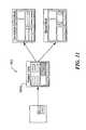
- FIG. 1is a diagrammatic depiction of a cryogenic catheter system in accordance with the present invention
- FIG. 2Ais a detailed view of a spot-type catheter forming a part of the system of FIG. 1 ;
- FIG. 2Bis a detailed view of a linear-type catheter forming a part of the system of FIG. 1 ;
- FIG. 3is a schematic diagram of a refrigeration system that can form a part of the system of FIG. 1 ;
- FIG. 4is a schematic diagram of an injection section of the system of FIG. 1 ;
- FIG. 5is a schematic diagram of a recovery section of the refrigeration system of FIG. 1 ;
- FIG. 6is a schematic diagram of the system of FIG. 1 having a leak detection system
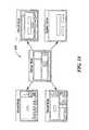
- FIG. 7is a pictorial and schematic diagram of console components
- FIG. 8is a schematic block diagram of a temperature control system of the console
- FIGS. 9 and 10are schematic block diagrams of watchdog system of the console
- FIG. 11shows exemplary procedure panels for being shown on a display that forms a portion of the console
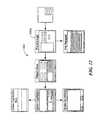
- FIG. 12shows exemplary recall panels for being shown on a display
- FIG. 13shows exemplary maintenance panels for being shown on a display
- FIG. 14shows exemplary warning/failure panels for being shown on a display.
- FIG. 1shows a cryogenic catheter system 100 in accordance with the present invention.
- the system 100includes a treatment catheter 102 coupled to a console 104 via an umbilical system 106 .
- the umbilical systemincludes an electrical umbilical 108 that contains signal lines for cardiac monitoring and/or mapping that are ultimately coupled to a an ECG monitor.
- the electrical umbilical 108can include an ECG box 111 to facilitate a connection from ring electrodes 116 ( FIGS. 2A-B ) to the ECG monitor.
- a coolant injection umbilical 112 and a coolant vacuum umbilical 110provide respective inlet and return paths for a refrigerant or coolant used to cool a tissue-treating end 114 of the catheter.
- the console 104provides a user interface to the system and houses the electronics and software for controlling and recording the ablation procedure, for controlling delivery of liquid refrigerant under high pressure through the umbilical to the catheter, for controlling the recovery of the expanded refrigerant vapor from the catheter under vacuum, and for controlling a compressor to pressurize the coolant vapor into a liquid stored in a recovery tank.
- the cryoablation system 100produces controlled cryogenic temperatures at the tip of a family of long, flexible catheters which can be inserted through various passages of the body.
- One application of the systemis delivering cold to the inner walls of a beating heart by approaching the heart through the body's vasculature from punctures in the skin. This procedure is done to correct electrophysiological abnormalities leading to irregular or errant heartbeats. It selectively destroys (ablates) the electrical characteristics of groups of heart cells (arrhythmogenic sites) which cause or propagate the abnormality.
- the cyroablation system 100can be used for any procedure that benefits from the application of extreme cold to tissue, and is therefore not limited to cardiac procedures.
- FIGS. 2A-Bshow two exemplary catheters in a family of sterile disposable catheters.
- FIG. 2Ashows a “spot” tip type catheter 102 a
- FIG. 2Bshows a “linear” tip type catheter 102 b .
- Both catheters 102 a,bcarry ring electrodes 116 for sensing the body's electrical signals and thermocouples 118 for sensing the temperature of the tip 114 .
- the ring electrodes 116aid the clinician in locating and verifying the sites of cardiac arrhythmia using standard intracardiac recording and in positioning the catheter to ablate the arrhythmogenic site.
- the spot tip catheter 102 ahas a small rounded tip 114 which contacts the heart in a “spot” yielding a concentrated zone of destruction.
- the tip temperatureis measured at an outside surface of the catheter tip.
- the linear catheter 102 bdelivers cold along a long cylindrical tip 114 to create a line of destruction in tissue. In certain cardiac procedures, this is done to block off the effects of entire sections of the heart which could lead to atrial fibrillation, atrial flutter, or some extensive ventricular tachyarrhythmias.
- the temperaturecan be measured at an inside surface of the catheter tip.
- FIG. 3shows a refrigeration system or mechanical assembly 150 that supplies refrigerant to the catheter 102 .
- the refrigerantexpands in the tip 114 of the catheter to cool it to a selected temperature.
- the refrigeration system 150includes an injection section 152 for providing liquid coolant to the catheter, a recovery section 154 for recovering the vaporized coolant, and an intermediate or evacuation section 156 for evacuating refrigerant remaining in the catheter after an injection procedure is terminated.
- the injection section 152provides liquid refrigerant on demand at a high variable pressure to the catheter 102 .
- the injection section 152includes a source of compressed gas 158 , e.g., CO2, coupled to a check valve 160 .
- a pressure regulator 162is coupled to the check valve 160 to bring the gas pressure down to an exemplary pressure of about 500 psia.
- the pressure regulator 162is connected to a refrigerant tank 164 that holds a refrigerant, such as AZ-20 refrigerant made by Allied Signal.
- a load cell 166used to measure the refrigerant level inside the tank, is placed in communication with the tank 164 .
- a second pressure regulator 168which is a proportional valve, is used to vary the refrigerant pressure from about 300 psia to 500 psia, for example.
- An injection solenoid valve 170is coupled to the second pressure regulator 168 to turn injection and on and off.
- a pressure transducer 172monitors injection pressure.
- Umbilical tubing 174 and catheter tubing 176provide a pathway for the refrigerant from the tank 164 to the catheter 102 .
- the compressed gas source 158When coolant is injected into the catheter tip, the compressed gas source 158 provides about 500 psia of pressure through the check valve 160 and the pressure regulator 162 to the refrigerant tank 164 .
- the gas pressurepushes liquid refrigerant from the tank through the proportional valve 168 , through the injection solenoid valve 170 , which is open, out of the console 104 and into the umbilical, and finally, into the catheter tubing.
- the proportional valve 168is used to control the pressure, which is monitored by a pressure transducer 172 in the injection line which, in turn, varies the flow rate of refrigerant to the catheter tip 102 .
- An increase in the flow rate(less restriction by the pressure regulator 168 ) lowers the temperature of the catheter tip.
- decreasing the coolant flow rateallows the catheter tip to be warmed by its surroundings, i.e. raises the tip temperature.
- the proportional valve 168is controlled by software, as described below.
- the recovery section 154provides a vacuum that creates a high differential pressure relative to the injection tube at the catheter tip 102 , causing the refrigerant to rapidly change to a gas state, thereby producing a dramatic drop in the temperature of the catheter tip.
- the recovery section 154also evacuates spent refrigerant from the catheter and re-condenses the vapor to a liquid state for safe storage and removal.
- Transducers 178monitor the gas pressures at various points to monitor operation of the coolant recovery.
- the recovery section 154 of the coolant systemincludes relatively large diameter catheter tubing 180 and umbilical tubing 182 coupled to a vacuum solenoid valve 184 .
- a vacuum check valve 186is coupled between the solenoid 184 and a flow meter 188 .
- a vacuum pump 190is coupled between input and output pressure transducers 178 .
- a second check valve 192is connected to the second pressure transducer and is also coupled to a compressor solenoid valve 194 .
- the compressor solenoid check valve 196is coupled to a compressor 198 for allowing refrigerant recovery in a refrigerant recovery tank 200 equipped with venting check valve 202 .
- a load cell 204is coupled to the tank 200 .
- the vacuum pump 190 and the compressor 198run whenever electrical power is being applied to the system. If coolant is not being injected, the compressor solenoid valve 194 is closed and any air that the vacuum pump 190 has drawn in is exhausted from the system through the check valve 202 . This prevents excess air from building up in the refrigerant recovery tank 200 .
- the pressure transducer 178 and the flow meter 188 in the recovery linecan detect if the catheter 102 is not connected to the system. If the catheter 102 is not connected, the vacuum solenoid valve 184 switches to atmosphere to prevent the vacuum pump 190 from pumping air, which will cause it to overheat.
- the vacuum solenoid valve 184closes to atmosphere and opens to the vacuum pump 190 , creating a deep vacuum (less than 0.2 psia) in the large diameter catheter and umbilical tubing 180 , 182 .
- the compressor solenoid valve 194When coolant injection is occurring, the compressor solenoid valve 194 is open.
- the vacuum in the large diameter catheter and umbilical tubingcreates a large pressure drop at the tip of the catheter 102 , causing the high pressure liquid refrigerant to suddenly expand into a gas and cool.
- the vacuumsucks the gas from the tubing, through the vacuum solenoid 184 , in through the vacuum pump 190 , through the compressor solenoid 194 and into the compressor 198 .
- the gasis then compressed to an exemplary pressure of about 240 psia (at 25° C.) to liquefy it, which is then pumped into the refrigerant recovery tank 200 .
- the check valve 202 on the tankvents off excess air that may have entered the system during catheter hookup.
- the evacuation system 156removes any refrigerant remaining in the injection line after injection has been terminated.
- the evacuation system 156includes a post injection solenoid valve 206 coupled to a 3-way vent valve 208 .
- Pressure transducers 172 , 210are coupled on either side of the solenoid valve 206 .
- the vent valve 208switches from the vacuum pump 190 inlet to the compressor 198 inlet.
- the post injection valve 206opens.
- the injection lines at the outlet of the injection solenoid 170now open to the inlet of the compressor 198 . This is done because as the refrigerant is evacuated from the lines, it expands dramatically and the vacuum pump 190 , under normal conditions, is not intended to handle this volume of gas.
- the pressure transducers in evacuation section 156measure the line pressures.
- an injection section of the cooling systemincludes a source of compressed gas, e.g., CO2 in a tank to which a check valve CV 6 is coupled.
- a primary pressure regulatorbrings the gas pressure down to about 600 psig and a secondary pressure regulator brings the pressure down to about 525 psig.
- Refrigerantsuch as AZ-20, is stored in a tank coupled to a differential pressure transducer for measuring the coolant level in the tank.
- a proportional valveis controlled by a PID (described below) for varying the coolant pressure from about 250 psig to about 500 psig.
- An injection solenoid valveactivates the injection circuit and a pressure transducer PT 1 monitors the injection pressure.
- the compressed gasprovides pushes liquid refrigerant from the tank, through the proportional valve.
- the SV 5is open only for two seconds, to let the catheter reach high flow which increases the cooling rate, so that it takes 30 seconds or less for the temperature to reach minus 35 degrees Centigrade or colder.
- the refrigerantflows through the injection SV 1 which is now open, out of the console and into the umbilical, and finally, into the small diameter catheter tubing.
- the proportional valveis used to vary the pressure, which is monitored by the pressure transducer PT 1 , and the proportional valve in the injection line varies the flow rate of refrigerant to the catheter tip.
- An increase in the flow rate(less restriction by the regulator) lowers the temperature of the catheter tip.
- decreasing the flow rateallows the catheter tip to be warmed by its surroundings.
- the proportional valvecan be adjusted on a console screen (mechanical monitoring) by setting the PID injection pressure and can be driven by system software in automatic mode.
- valves S 1 , S 2 , S 4 , S 5 and S 6are activated simultaneously. However, S 5 is turned off about two seconds later. Valve S 5 fills the umbilical injection section tube and improves the cooling rate.
- Softwarecontrols the pressure regulator based on the optimal position calculated by the PID temperature controller, which is described below.
- the recovery section of the plumbing circuitserves two primary functions. The first is to provide a vacuum which creates a high differential pressure relative to the injection tube at the catheter tip. This causes the refrigerant to rapidly change to a gas state, producing a dramatic drop in the temperature of the tip. The second primary function is to evacuate the spent refrigerant from the catheter and to recondense it to a liquid state for safe storage and removal. Transducers monitor the gas pressures at various points in the recovery plumbing.
- a vacuum solenoid valve SV 3has check valves CV 1 ,CV 2 coupled on either side with a mass flowmeter connected inline to monitor the flow rate.
- Pressure transducers PT 2 - 5monitor pressure at various points in the recovery section.
- a vacuum pumpis coupled to the compressor and a condenser is coupled to the compressor to facilitate coolant recovery into the recovery tank.
- the vacuum pump and compressorare running when electrical power is applied to the system. If an injection of refrigerant is not taking place, the compressor solenoid valve SV 4 is closed and any air that the vacuum pump may draw in is exhausted from the system through the solenoid valve SV 4 . This prevents excess air from building up in the refrigerant recovery tank.
- a pressure transducer and a flowmeter in the recovery linecan detect if a catheter is not connected to the system. If a catheter is not connected, the vacuum solenoid valve SV 3 switches to atmosphere to prevent the vacuum pump from pumping air, which will cause it to overheat. If a catheter is connected, in the no injection “idle” mode, the vacuum solenoid valve closes to atmosphere and opens to the vacuum pump, creating a deep vacuum (less than 0.5 psia) in the catheter and umbilical tubing.
- the compressor solenoid valveopens.
- the vacuum in the catheter and umbilical tubingcreates a large pressure drop at the tip of the catheter, causing the high pressure liquid refrigerant to suddenly expand into a gas and cool.
- the vacuumsucks the gas from the tubing, through the vacuum solenoid SV 3 , in through the vacuum pump, through the SV 4 and into the compressor.
- the gasis then compressed until at about 240 psig (at 25° C.), it liquefies through the condenser and is pumped into the refrigerant recovery tank.
- There is a 350 psig check valve on the tankthat vents off CO2 and excess air that may have entered the system during catheter hookup.
- the refrigerant tank levelmeasured by the load cell, is considered “full” when it is 80% full of liquid refrigerant.
- Valves S 1 , S 5 and S 6are inactive during evacuation while valves S 2 , S 4 , and S 3 are active.
- the watchdog systemwhich is described below, closes the pressure regulator.
- FIG. 6shows the cryogenic catheter system 100 having a leak detection system for detecting a fluid, such as blood, within the closed coolant flow network.
- the leak detection systemincludes a first sensor 300 located in the catheter tip 114 .
- the first sensor 300detects the presence of blood internal to the catheter tip 114 .
- the first sensor 300measures the impedance between a dummy wire inside the catheter and the catheter tip. If the impedance is outside a predetermined range, the first sensor 300 provides a blood detection signal to the console, which then stops the flow of injection fluid but maintains the coolant vacuum.
- the leak detection systemfurther includes a second sensor 302 located in the catheter handle 304 for detecting blood within the coolant stream.
- the second sensor 302is an optical type sensor. Upon detecting blood in the coolant, the second sensor 302 provides an indication to the console 104 , which then terminates vacuum pressure on the coolant to prevent blood from being removed the patient.
- the leak detection systemcan also include a third sensor 306 located in the console 104 in communication with the coolant return path.
- the third sensor 306detects a liquid, such as blood, within the coolant recovery path, the console 104 terminates vacuum pressure to prevent the blood from reaching the vacuum pump 190 (FIG. 3 ).
- FIG. 7shows an exemplary embodiment of the console 104 having an LCD touch screen that displays console status and data, and accepts user data and control inputs.
- a user interface 402includes a start (injection) button 402 b allows the injecting refrigerant into the catheter and a stop (injection) button 402 c stops the delivery of refrigerant.
- the stop injection button 402 coverrides software control in automatic mode, thus acting as an emergency backup control.
- An injection on light 402 dilluminates when the start injection button 402 b is pressed and remains illuminated until refrigerant injection is stopped.
- An LED temperature readout 402 edisplays the actual catheter tip temperature as measured by a thermocouple 118 ( FIG. 2B ) located in the catheter tip. The LED display independently confirms the temperature displayed on the touch screen.
- a standard ISA bus 404is coupled to a CPU 406 , a touch screen control 408 , and a data acquisition interface (DAI) 410 , along with various peripheral devices, such as a hard disk 412 and a floppy disk 414 .
- the DAI 410contains signal conditioning circuits required for conveying information to the CPU 406 .
- the CPU 406acts as a graphical display controller, patient data processor, and controller for automatic operation modes.
- a patient interface 418is coupled to the data acquisition interface 410 , and is connected to the catheter 102 through a patient overload protection module 420 and an ECG connection box 422 .
- the patient interface 418transmits system operating parameters including catheter tip temperature, catheter type (spot/elongate) and connection status across an electrical isolation barrier and ultimately to the CPU 406 .
- An electro mechanical interface 424contains various driver circuits for the controlling components, e.g., valves, in the mechanical assembly 426 , e.g., the refrigeration system 150 (FIG. 3 ), and driver circuits for interfacing to the front panel controls & indicators box 402 .
- a PID controller 428generates a control voltage to drive the proportional valve 168 to control the pressure in the mechanical assembly 424 (refrigeration system 150 , FIG. 3 ).
- An audio generator 430synthesizes audio tones that correspond to pressing panel control keys, injection status on, and console warnings or failures.
- the audio generatoractivates a speaker 432 that generates the sounds corresponding to the audio tones.
- a watchdog system 434is coupled to the mechanical assembly 426 via the electromechanical interface 424 .
- the watchdog system 434receives data from the data acquisition interface 410 for generating control signals for the mechanical assembly 426 .
- the watchdog system 434directly controls the injection valve 170 (FIG. 3 ), the vent valve 208 , and the vacuum valve 184 in the mechanical assembly.
- the watchdog system 434also monitors console status and generates warning and failure signals and controls failure states of the mechanical assembly.
- the watchdog system 434is implemented in a field programmable gate array (FPGA).
- FIG. 8shows an exemplary implementation of the pressure control circuit.
- the pressure controller circuitincludes a PID used to control the proportional valve. This valve controls the injection pressure which enables the system to operate at pressures ranging from 250 to 500 psig.
- a pressure transducer PT- 1is mounted at the outlet of the injection valve SV 1 . The sensor PT- 1 output and the requested temperature set point are fed to a differentiator. The difference signal activates an integrator which in turn activates a driver of the proportional valve.
- the delivery pressureis set to fixed set point of 500 psig.
- the systemcontrols the delivery pressure of the refrigerant in order to reach and maintain a selected temperature. This continuous temperature control assures compensation of the heat load changes due to the blood movement during a cardiac cycle or due to changes in the adhesion between the catheter tip and the tissues.
- Tip temperature controlis performed using two control loops, a hardware pressure control loop and a software temperature control loop.
- Softwarecontrols the tip temperature by reading the current tip temperature via a thermocouple and determines the required delivery pressure setpoint using a PID algorithm based on digital proportional-integral-derivative (PID) compensator.
- PIDdigital proportional-integral-derivative
- the pressure set pointis sent to the hardware pressure controller, which assures continuous control of the proportional valve based on a pressure transducer reading.
- a redundant hardware systemis implemented as part of the watchdog system to monitor the pressure setpoint sent by the software. This feature insures that the set point will never exceed the allowable operating pressure of 500 psig. Furthermore, the Watchdog system monitors the state of the CPU and the software in order to detect a freezes or abnormal loops and takes action on kicking the mechanical plumbing into a safe mode. Another important feature of the Watchdog system is to block the analog setpoint controlled by the CDM whenever an injection OFF is requested or a failure is generated.
- FIGS. 9 and 10show an exemplary configuration for the watchdog system including a Field Programmable Gate Array.
- the watchdog systemmonitors both injection and vacuum functions for failures and degraded operational performance of the mechanical plumbing in order to safely start and end the procedure at any time.
- the injection valveis controlled only through the Watchdog system. The only control that software would act over the injection valve is to turn OFF the injection when automatic timing is requested.
- the Watchdog systemprocesses information acquired from system and generates failures and warnings. Warning alerts are generated when patient safety is not compromised and the procedure can be continued. Failure alerts are generated when patient safety is potentially compromised and the system puts itself into a Safe Mode State. For each failure or warning, the system can provide an automatic safe system default, a visual indication light, an audible alarm, and a visual informative message on the screen.
- the watchdog systemis a combination of discrete circuits and a FPGA chip.
- the FPGAprocesses the failures and warnings and controls the electromechanical valves based on the user requests. Redundant circuits around the FPGA prevent a single fault hazardous failure of this device.
- a user request backup circuitreceives the same user requests from the user interface controls and produces the same action that the FPGA would produce. This redundant circuit insures that the injection stops when an injection OFF is requested in both cases when the FPGA or the backup circuit fails to respond.
- a second redundant circuitis designed with discrete component and used to monitor the valve control lines that are set by the FPGA. This circuit compares FPGA output lines to a set of predefined values based on the system State and insure that the FPGA is sending the right valve sequence. Should a valve sequence not match the predefined values a failure is generated and a message is sent to the software in order to warn the user.
- An independent external watchdog timeris implemented on the CPU board to monitor the software and CPU status which secure the system uses in case a software freeze.
- a control lineis sent to the FPGA indicating a software or CPU freeze.
- the FPGAprocesses signals supplied from different parts of the system in order to determine the state of the system and provide control lines to the valve interface circuit. Should an alert condition be captured, the FPGA generates and prioritizes audio signals.
- the softwarecommunicates with this device through the data acquisition board.
- the electromechanical transducer outputsare fed to a block of comparators which compare the current transducer value to a predefined threshold.
- the input block of the FPGAincludes the system state processing unit, which process the status lines.
- the output lines of the processing unitare fed to a failure/warning unit which determine if the condition result is a failure or warning based on the user request.
- the second blockis the failure latch block which receives all processed condition lines and feeds them to a large OR gate.
- the latch blockallows the capture of fast abnormal events. Failure, warning and other functional lines are fed to a priority selector block which processes the signal origin and prioritizes the audio signals. Failure audio signal has the highest priority.
- the audio signalis fed to the audio synthesizer, which produces the audio enable/disable signals that are sent to audio circuit.
- Another function of the FPGAis to generate the system states ( FIGS. 9-10 ) and control the electromechanical valves based on the user requests. Prior to the valve control, the FPGA verifies the hardware and system status and sets the valve control lines.
- the FPGAverifies the failure/warning lines before any action is transmitted to the valves. Once the user request is accepted the valve control block sets each valve to the appropriate position and sets the appropriate audio tone.
- Another function of the FPGAis to provide an input/output port to the software.
- the softwareacquires the information regarding the alert through an input data selector which provides access to all condition lines as processed by the system state processing unit.
- An output data selectoris implemented inside the FPGA which allows to increase the number of digital output lines provided by the data acquisition board.
- the cryogenic catheter system 100includes software, which is executed by the CPU 406 , for controlling the overall operation of the system by acquiring data from the system hardware components, for saving data on the system hard disk, and displaying data on the system display screens.
- the softwareinitiates the hardware components and begins a system self test.
- FIGS. 11-14show exemplary display panels for allowing a user to select a desired action for the system.
- a useris allowed to select one of three options on the touch screen 400 . More particularly, the user can instruct the software to access a procedure panel 500 , a recall panel 502 , or a maintenance panel 504 .
- a failure/warning panel 506is displayed upon detecting a system fault.
- the display 400shows a patient data panel 500 a where patient information is entered and saved to the hard disk.
- the userwill be able to choose the type of procedure to run.
- the optionsinclude a “spot” procedure in either manual or automatic mode , or a “linear” procedure which is only available in manual mode.
- the sofwarecontiniously displays certain information on the touch screen 400 and saves temperature profile information to the hard disk for future recall. If a system failure is detected during the procedure, the software will stop saving the temperature profiles and open a separate file where it will log the current state of the system.
- a file manager panel 502 ais displayed. This allows the user to select from the list of previously run procedures. The selected file may then be opened for viewing, copied to a floppy disk, or deleted from the hard disk.
- the maintenance panel 504( FIG. 23 ) aids maintenance personnel in performing routine system maintenance and to help technical personnel in troubleshooting system failures. To prohibit unauthorized personnel from accessing low level system information, certain troubleshooting panels can be password protected.
- the warning/failure panel 506( FIG. 14 ) displays warning and failure information when a system fault is detected, as described above in connection with the watchdog system 434 . Exemplary warning and failure conditions are listed below in Table 3.
- the systemprotects the patients from unsafe conditions while allowing the system to operate in the presence of warning conditions that do not compromise patient safety.
- the watchdog systemmonitors the umbilical electrical connections from the catheter to the console. If continuity is lost and injection is Off, the system generates a warning. Should the user ignore the warning message and try to initiate an injection a failure is generated and injection is disabled. If the continuity is lost and injection is On, the system generates a failure and stops injection.
- the systemmonitors the injection connectors at both the console and catheter side by measuring the baseline flow of the system. Should a baseline flow higher than 150 sccm be detected a warning is generated.
- FIG. 26graphically shows flow rate conditions. The system detects if either side is not connected and disables injection. If either side is not connected and injection is Off, the system generates a warning. Should the user ignore the warning message and try to initiate an injection a failure is generated and injection is disabled.
- the systemalso monitors the vacuum connections at both the console and catheter side. If either side is not connected, the system disables the injection. If either side is not connected and injection is OFF, the system generates a warning. Should the user ignore the warning message and try to initiate an injection a failure is generated and injection is disabled. If either side is not connected and injection is ON, the system generates a failure and stops injection.
- the systemuses thermocouples to measure the tip temperatures, the integrity of the electrical connection is verified each time the electrical connection of the catheter is connected to the console. Lack of electrical connector integrity could happen during or after sterilization/shipping process or by an improper pin configuration. Detection is done through the software, which acquires the distal and proximal temperatures. Should the tip temperature reading be less than +30 C. or higher than +45° C., the system can display a message, disable the procedure panel, and/or disable injection.
- the cryoablation systemrecognizes the type of cryoablation catheter, which is connected to the console, and then compares catheter type to the selected software panel. If catheter type is not compatible with the selected software panel, the system displays a message, locks out the procedure panel and disable injection.
- Baseline flowis defined as the vapor flow measured at the inlet of the vacuum pump when both mechanical umbilical tube are connected to the catheter and console and the injection is OFF. Since the system is not perfectly leak tight, a small baseline flow always exists. The maximum allowable baseline flow is 150 sccm. When a high baseline flow is detected, the system generates a warning. Should the user ignore the warning message and tried to initiate an injection request, the system switch from warning mode to a failure mode.
- Refrigerant vapor flowis measured at the inlet of the vacuum pump. If the flow is outside predefined parameters, a failure is generated. This implies that refrigerant is being lost somewhere because of a variety of possible failures, including but not limited to abnormal refrigerant recovery.
- This detectionis performed by comparing the actual vapor flow curve to a predefined flow curve specific to each type of catheter. The comparison is done point to point which provides a in real time detection.
- the threshold of the excessive flowis specific to each catheter type.
- the systemconstantly monitors the catheter tip temperature during the mapping mode when only a spot catheter is used. Should the tip temperature drops below ⁇ 47° C. during cold mapping the system automatically stops the injection and generates a failure.
- the systemconstantly monitors the catheter tip temperature during the ablation mode when both catheter types are used. Should the tip temperature not drop below ⁇ 50 C. after 75 seconds of injection, the system generates a warning message indicating that the current temperature is reachable temperature and the clinician has the choice to stop relocating the catheter or continue if clinical effect occurred.
- a leak detectoris built in to the tip of the catheter provided by CryoCath.
- a high impedanceexists between the catheters active electrode and the common point of the catheters thermocouples. If blood enters the catheter tip, this impedance drops substantially. If a leak is detected during a procedure, the system stops injection, maintains vacuum in order to draw back the refrigerant vapor, and produces a system failure indication
- the systemalso detects blood in the catheter handle. If blood is detected during a procedure, the system stops injection, stops the vacuum in the umbilical, and produces a system failure indication.
- the systemhas three tanks that are monitored all the time and the user is warned when abnormal tank capacity is presented.
- Tank capacitiesare designed in a manner that they match each other which, allow tank changes to be done at the same time.
- the watchdog systemmonitors tank levels during the procedure and the software checks these levels at system power up in order to prevent the necessity of changing tanks during a procedure.
- the systemhas two operative threshold detection stages. At power-up, if there is insufficient capacity for one procedure, injection must be disabled so a procedure cannot begin. The system will not function until the appropriate tanks are replaced. Furthermore, should a tank level drop below the operative threshold during a procedure, a warning signal is generated informing the user that he is able to continue the procedure, however the appropriate tanks must be replaced prior to the next procedure. If the level progresses to the point where it cannot support the current procedure, a failure is to be generated and the procedure must be terminated.
- a full procedure for the Spot Lesion Catheteris defined as 20 injections ⁇ 2 minutes @ 700 sccm for cold mapping and 10 injections ⁇ 5 minutes @ 1200 for ablation. For example, at this rate a full 6.5 lb tank treat four patients.
- a full atrial flutter procedure for the 25 mm Linear Catheteris defined as 10 injections ⁇ 5 minutes @ 2800 sccm. For example, at this rate, a full 6.5 lb tank treat four patients.
- the systemWhen the gas pressure drops below 650 psig ( ⁇ 5 psig ), the system produces a failure and disable injection if detected during power-up testing, produces a warning if detected during a procedure. When the gas pressure drops below 525 psig ( ⁇ 5 psig), a failure is produced which disables injection, thus stopping the procedure.
- the systemWhen the level of refrigerant drops below 20% ( ⁇ 1%) of tank capacity, the system produces a failure and disable injection if detected during power-up testing, produces a warning if detected during a procedure. When the level of refrigerant drops below 5% ( ⁇ 1%) of tank capacity, a failure be produced which disables injection, thus stopping the procedure.
- the systemstops injection, stops the vacuum and produces a system failure indication.
- the systemfurther monitors the vacuum pump and the compressor for malfunctions, as well as software for freezes. Should the software freezes for more than 2 seconds, the watchdog timer generates a signal to the FPGA.
- the temperature of the refrigerant at the consoleneeds to stay below a maximum value. For AZ-20, this maximum temperature is 30° C. If the refrigerant temperature is too warm, the refrigerant is more susceptible to the formation of gas bubbles during mapping mode, this is due to the increase of the critical temperature of the refrigerant. These bubbles, when moving past the catheter tip, cause the temperature of the tip to oscillate around the preset temperature, thus affecting the cooling power of the tip.
- the systemmonitors the temperature of the liquid refrigerant at the console procedure panel during injection. If the temperature rises above 30° C., the system stops the injection and creates a failure
- Electro-mechanical valve monitoringis provided to ensure proper functioning of the mechanical system. Should a valve fail, the FPGA stops the injection and evacuates the umbilical lines.
- the system 100can monitor system operation through testing during power-up and from hardware.
- the systemoperates in the presence of a problem during a procedure unless patient safety is compromised. That is, a procedure in progress is allowed to finish unless there is a risk to the patient by continuing the procedure. If, however, a failure is detected when power is first applied, the user is not allowed to begin a procedure with a known failure present. This is controlled with the enabling of the injection valve 170 (FIG. 3 ), which delivers refrigerant to the catheter 102 .
- the injection valve 170is not enabled until power-up tests have been successfully completed. If any test fails, the valve 170 is not enabled and pressing the injection on button has no effect.
Landscapes
- Health & Medical Sciences (AREA)
- Surgery (AREA)
- Life Sciences & Earth Sciences (AREA)
- Nuclear Medicine, Radiotherapy & Molecular Imaging (AREA)
- Animal Behavior & Ethology (AREA)
- Veterinary Medicine (AREA)
- Biomedical Technology (AREA)
- Heart & Thoracic Surgery (AREA)
- Medical Informatics (AREA)
- Molecular Biology (AREA)
- Otolaryngology (AREA)
- General Health & Medical Sciences (AREA)
- Public Health (AREA)
- Engineering & Computer Science (AREA)
- Thermotherapy And Cooling Therapy Devices (AREA)
- Surgical Instruments (AREA)
- Media Introduction/Drainage Providing Device (AREA)
- Examining Or Testing Airtightness (AREA)
- External Artificial Organs (AREA)
- Superconductors And Manufacturing Methods Therefor (AREA)
- Measuring And Recording Apparatus For Diagnosis (AREA)
- Measuring Pulse, Heart Rate, Blood Pressure Or Blood Flow (AREA)
Abstract
Description
Claims (10)
Priority Applications (1)
| Application Number | Priority Date | Filing Date | Title |
|---|---|---|---|
| US10/252,501US6887234B2 (en) | 1999-01-25 | 2002-09-23 | Cryogenic catheter system |
Applications Claiming Priority (3)
| Application Number | Priority Date | Filing Date | Title |
|---|---|---|---|
| US11717599P | 1999-01-25 | 1999-01-25 | |
| US09/489,644US6468268B1 (en) | 1999-01-25 | 2000-01-24 | Cryogenic catheter system |
| US10/252,501US6887234B2 (en) | 1999-01-25 | 2002-09-23 | Cryogenic catheter system |
Related Parent Applications (1)
| Application Number | Title | Priority Date | Filing Date |
|---|---|---|---|
| US09/489,644ContinuationUS6468268B1 (en) | 1999-01-25 | 2000-01-24 | Cryogenic catheter system |
Publications (2)
| Publication Number | Publication Date |
|---|---|
| US20030018326A1 US20030018326A1 (en) | 2003-01-23 |
| US6887234B2true US6887234B2 (en) | 2005-05-03 |
Family
ID=22371346
Family Applications (10)
| Application Number | Title | Priority Date | Filing Date |
|---|---|---|---|
| US09/489,644Expired - LifetimeUS6468268B1 (en) | 1999-01-25 | 2000-01-24 | Cryogenic catheter system |
| US09/489,646Expired - LifetimeUS6383180B1 (en) | 1999-01-25 | 2000-01-24 | Closed loop catheter coolant system |
| US09/489,707Expired - LifetimeUS6569158B1 (en) | 1999-01-25 | 2000-01-24 | Leak detection system |
| US10/115,213Expired - LifetimeUS6682525B2 (en) | 1999-01-25 | 2002-04-01 | Closed loop catheter coolant system |
| US10/124,558Expired - LifetimeUS6733494B2 (en) | 1999-01-25 | 2002-04-17 | Leak detection system |
| US10/124,560Expired - LifetimeUS6761714B2 (en) | 1999-01-25 | 2002-04-17 | Leak detection system |
| US10/252,501Expired - LifetimeUS6887234B2 (en) | 1999-01-25 | 2002-09-23 | Cryogenic catheter system |
| US10/764,661Expired - LifetimeUS7303554B2 (en) | 1999-01-25 | 2004-01-26 | Closed loop catheter coolant system |
| US10/889,620Expired - Fee RelatedUS7404816B2 (en) | 1999-01-25 | 2004-07-12 | Leak detection system |
| US11/948,321Expired - Fee RelatedUS8454587B2 (en) | 1999-01-25 | 2007-11-30 | Closed loop catheter coolant system |
Family Applications Before (6)
| Application Number | Title | Priority Date | Filing Date |
|---|---|---|---|
| US09/489,644Expired - LifetimeUS6468268B1 (en) | 1999-01-25 | 2000-01-24 | Cryogenic catheter system |
| US09/489,646Expired - LifetimeUS6383180B1 (en) | 1999-01-25 | 2000-01-24 | Closed loop catheter coolant system |
| US09/489,707Expired - LifetimeUS6569158B1 (en) | 1999-01-25 | 2000-01-24 | Leak detection system |
| US10/115,213Expired - LifetimeUS6682525B2 (en) | 1999-01-25 | 2002-04-01 | Closed loop catheter coolant system |
| US10/124,558Expired - LifetimeUS6733494B2 (en) | 1999-01-25 | 2002-04-17 | Leak detection system |
| US10/124,560Expired - LifetimeUS6761714B2 (en) | 1999-01-25 | 2002-04-17 | Leak detection system |
Family Applications After (3)
| Application Number | Title | Priority Date | Filing Date |
|---|---|---|---|
| US10/764,661Expired - LifetimeUS7303554B2 (en) | 1999-01-25 | 2004-01-26 | Closed loop catheter coolant system |
| US10/889,620Expired - Fee RelatedUS7404816B2 (en) | 1999-01-25 | 2004-07-12 | Leak detection system |
| US11/948,321Expired - Fee RelatedUS8454587B2 (en) | 1999-01-25 | 2007-11-30 | Closed loop catheter coolant system |
Country Status (6)
| Country | Link |
|---|---|
| US (10) | US6468268B1 (en) |
| EP (3) | EP1148833B1 (en) |
| AT (2) | ATE243982T1 (en) |
| CA (5) | CA2707199C (en) |
| DE (2) | DE60003635T2 (en) |
| WO (3) | WO2000042931A1 (en) |
Cited By (28)
| Publication number | Priority date | Publication date | Assignee | Title |
|---|---|---|---|---|
| US20090299357A1 (en)* | 2006-04-24 | 2009-12-03 | Thomas Jefferson University | Cryoneedle and cryotheraphy system |
| US20100057064A1 (en)* | 2008-09-03 | 2010-03-04 | Baust John M | Medical Device for the Transport of Subcooled Cryogenic Fluid through a Linear Heat Exchanger |
| US20100057067A1 (en)* | 2008-09-03 | 2010-03-04 | Baust John M | Modular pulsed pressure device for the transport of liquid cryogen to a cryoprobe |
| US20100076421A1 (en)* | 2008-09-19 | 2010-03-25 | Baust John M | Nucleation Enhanced Surface Modification to Support Physical Vapor Deposition to Create a Vacuum |
| US7799018B2 (en) | 2006-01-06 | 2010-09-21 | Olga Goulko | Cryogenic applicator for rejuvenating human skin and related method |
| US20100241114A1 (en)* | 2009-03-20 | 2010-09-23 | Salvatore Privitera | Cryogenic probe |
| US20110152849A1 (en)* | 2008-09-03 | 2011-06-23 | Baust John M | Cryogenic System and Method of Use |
| US20110184401A1 (en)* | 2008-07-15 | 2011-07-28 | Kansei Iwata | Cryotherapy planning device and cryotherapy device |
| US20130197501A1 (en)* | 2012-01-27 | 2013-08-01 | Medtronic Cryocath Lp | Cryogenic medical system and method with stabilizer |
| WO2014137383A1 (en)* | 2013-03-04 | 2014-09-12 | Csa Medical, Inc. | Cryospray catheters |
| JP2015509791A (en)* | 2012-03-02 | 2015-04-02 | シーエスエイ・メディカル・インコーポレイテッドCsa Medical, Inc. | Cryosurgery system |
| US9089316B2 (en) | 2009-11-02 | 2015-07-28 | Endocare, Inc. | Cryogenic medical system |
| US9144449B2 (en) | 2012-03-02 | 2015-09-29 | Csa Medical, Inc. | Cryosurgery system |
| US9861422B2 (en) | 2015-06-17 | 2018-01-09 | Medtronic, Inc. | Catheter breach loop feedback fault detection with active and inactive driver system |
| US9867648B2 (en) | 2014-06-04 | 2018-01-16 | Csa Medical, Inc. | Method and system for consistent, repeatable, and safe cryospray treatment of airway tissue |
| US10045817B2 (en) | 2010-11-16 | 2018-08-14 | Tva Medical, Inc. | Devices and methods for forming a fistula |
| US10603040B1 (en) | 2015-02-09 | 2020-03-31 | Tva Medical, Inc. | Methods for treating hypertension and reducing blood pressure with formation of fistula |
| US10646666B2 (en) | 2014-08-27 | 2020-05-12 | Tva Medical, Inc. | Cryolipolysis devices and methods therefor |
| US10695534B2 (en) | 2014-03-14 | 2020-06-30 | Tva Medical, Inc. | Fistula formation devices and methods therefor |
| US10821217B2 (en) | 2013-03-14 | 2020-11-03 | Tva Medical, Inc. | Fistula formation devices and methods therefor |
| US10869717B2 (en) | 2012-10-11 | 2020-12-22 | Tva Medical, Inc. | Devices and methods for fistula formation |
| US10874422B2 (en) | 2016-01-15 | 2020-12-29 | Tva Medical, Inc. | Systems and methods for increasing blood flow |
| US11026743B2 (en) | 2016-01-15 | 2021-06-08 | Tva Medical, Inc. | Devices and methods for forming a fistula |
| US11202559B2 (en) | 2016-04-27 | 2021-12-21 | Csa Medical, Inc. | Vision preservation system for medical devices |
| US11285028B2 (en) | 2016-09-25 | 2022-03-29 | Tva Medical, Inc. | Vascular stent devices and methods |
| US11590322B2 (en) | 2016-01-15 | 2023-02-28 | Tva Medical, Inc. | Devices and methods for advancing a wire |
| US11871977B2 (en) | 2016-05-19 | 2024-01-16 | Csa Medical, Inc. | Catheter extension control |
| US12295645B2 (en) | 2016-01-15 | 2025-05-13 | Tva Medical, Inc. | Systems and methods for adhering vessels |
Families Citing this family (207)
| Publication number | Priority date | Publication date | Assignee | Title |
|---|---|---|---|---|
| US6096037A (en) | 1997-07-29 | 2000-08-01 | Medtronic, Inc. | Tissue sealing electrosurgery device and methods of sealing tissue |
| US6312452B1 (en) | 1998-01-23 | 2001-11-06 | Innercool Therapies, Inc. | Selective organ cooling catheter with guidewire apparatus and temperature-monitoring device |
| US6719779B2 (en) | 2000-11-07 | 2004-04-13 | Innercool Therapies, Inc. | Circulation set for temperature-controlled catheter and method of using the same |
| US6905494B2 (en) | 1998-03-31 | 2005-06-14 | Innercool Therapies, Inc. | Method and device for performing cooling- or cryo-therapies for, e.g., angioplasty with reduced restenosis or pulmonary vein cell necrosis to inhibit atrial fibrillation employing tissue protection |
| US6602276B2 (en) | 1998-03-31 | 2003-08-05 | Innercool Therapies, Inc. | Method and device for performing cooling- or cryo-therapies for, e.g., angioplasty with reduced restenosis or pulmonary vein cell necrosis to inhibit atrial fibrillation |
| US7291144B2 (en) | 1998-03-31 | 2007-11-06 | Innercool Therapies, Inc. | Method and device for performing cooling- or cryo-therapies for, e.g., angioplasty with reduced restenosis or pulmonary vein cell necrosis to inhibit atrial fibrillation |
| US7001378B2 (en) | 1998-03-31 | 2006-02-21 | Innercool Therapies, Inc. | Method and device for performing cooling or cryo-therapies, for, e.g., angioplasty with reduced restenosis or pulmonary vein cell necrosis to inhibit atrial fibrillation employing tissue protection |
| US6685732B2 (en) | 1998-03-31 | 2004-02-03 | Innercool Therapies, Inc. | Method and device for performing cooling- or cryo-therapies for, e.g., angioplasty with reduced restenosis or pulmonary vein cell necrosis to inhibit atrial fibrillation employing microporous balloon |
| US6468268B1 (en)* | 1999-01-25 | 2002-10-22 | Cryocath Technologies Inc. | Cryogenic catheter system |
| US20050228367A1 (en)* | 1999-01-25 | 2005-10-13 | Marwan Abboud | Leak detection system for catheter based medical device |
| WO2006124177A1 (en)* | 1999-01-25 | 2006-11-23 | Cryocath Technologies Inc. | Leak detection system for catheter based medical device |
| US6592577B2 (en)* | 1999-01-25 | 2003-07-15 | Cryocath Technologies Inc. | Cooling system |
| US6648879B2 (en) | 1999-02-24 | 2003-11-18 | Cryovascular Systems, Inc. | Safety cryotherapy catheter |
| US6432102B2 (en) | 1999-03-15 | 2002-08-13 | Cryovascular Systems, Inc. | Cryosurgical fluid supply |
| US6514245B1 (en) | 1999-03-15 | 2003-02-04 | Cryovascular Systems, Inc. | Safety cryotherapy catheter |
| US20030028182A1 (en)* | 1999-04-21 | 2003-02-06 | Cryocath Technologies Inc. | Cryoablation catheter handle |
| US7905879B2 (en)* | 1999-04-21 | 2011-03-15 | Medtronic Cryocath Lp | Cryoablation catheter handle |
| US7004936B2 (en)* | 2000-08-09 | 2006-02-28 | Cryocor, Inc. | Refrigeration source for a cryoablation catheter |
| US6237355B1 (en)* | 1999-06-25 | 2001-05-29 | Cryogen, Inc. | Precooled cryogenic ablation system |
| US6471694B1 (en)* | 2000-08-09 | 2002-10-29 | Cryogen, Inc. | Control system for cryosurgery |
| US7527622B2 (en)* | 1999-08-23 | 2009-05-05 | Cryocath Technologies Inc. | Endovascular cryotreatment catheter |
| US6447443B1 (en) | 2001-01-13 | 2002-09-10 | Medtronic, Inc. | Method for organ positioning and stabilization |
| GB2360573B (en)* | 2000-03-23 | 2002-05-22 | Spembly Medical Ltd | Refrigeration instrument and system |
| US6932811B2 (en) | 2000-04-27 | 2005-08-23 | Atricure, Inc. | Transmural ablation device with integral EKG sensor |
| US20020107514A1 (en) | 2000-04-27 | 2002-08-08 | Hooven Michael D. | Transmural ablation device with parallel jaws |
| US6546935B2 (en) | 2000-04-27 | 2003-04-15 | Atricure, Inc. | Method for transmural ablation |
| US6905498B2 (en) | 2000-04-27 | 2005-06-14 | Atricure Inc. | Transmural ablation device with EKG sensor and pacing electrode |
| US6602246B1 (en)* | 2000-08-18 | 2003-08-05 | Cryovascular Systems, Inc. | Cryotherapy method for detecting and treating vulnerable plaque |
| US6706037B2 (en)* | 2000-10-24 | 2004-03-16 | Galil Medical Ltd. | Multiple cryoprobe apparatus and method |
| US20020068929A1 (en)* | 2000-10-24 | 2002-06-06 | Roni Zvuloni | Apparatus and method for compressing a gas, and cryosurgery system and method utilizing same |
| US20080045934A1 (en)* | 2000-10-24 | 2008-02-21 | Galil Medical Ltd. | Device and method for coordinated insertion of a plurality of cryoprobes |
| US20020188287A1 (en)* | 2001-05-21 | 2002-12-12 | Roni Zvuloni | Apparatus and method for cryosurgery within a body cavity |
| US7628780B2 (en) | 2001-01-13 | 2009-12-08 | Medtronic, Inc. | Devices and methods for interstitial injection of biologic agents into tissue |
| US20080051774A1 (en)* | 2001-05-21 | 2008-02-28 | Galil Medical Ltd. | Device and method for coordinated insertion of a plurality of cryoprobes |
| US20080051776A1 (en)* | 2001-05-21 | 2008-02-28 | Galil Medical Ltd. | Thin uninsulated cryoprobe and insulating probe introducer |
| US20040243118A1 (en)* | 2001-06-01 | 2004-12-02 | Ayers Gregory M. | Device and method for positioning a catheter tip for creating a cryogenic lesion |
| US6607517B1 (en)* | 2001-08-24 | 2003-08-19 | Radiant Medical, Inc. | Method of inotropic treatment of heart disease using hypothermia |
| AU2002359814A1 (en)* | 2001-12-19 | 2003-07-09 | Ran Yaron | Miniature refrigeration system for cryothermal ablation catheter |
| US6991630B2 (en)* | 2002-02-01 | 2006-01-31 | Cryocor, Inc. | Non-charging pre-cooling system |
| US7004937B2 (en)* | 2002-07-31 | 2006-02-28 | Cryocor, Inc. | Wire reinforced articulation segment |
| US20040024392A1 (en)* | 2002-08-05 | 2004-02-05 | Lewis James D. | Apparatus and method for cryosurgery |
| US20040034344A1 (en)* | 2002-08-16 | 2004-02-19 | Eric Ryba | Tip pressure monitoring for cryoablation catheters |
| US6955673B2 (en)* | 2002-08-16 | 2005-10-18 | Cryocor, Inc. | Heat transfer segment for a cryoablation catheter |
| US20040034365A1 (en)* | 2002-08-16 | 2004-02-19 | Lentz David J. | Catheter having articulation system |
| IL151486A0 (en)* | 2002-08-26 | 2003-04-10 | Levin Alexander | Cryosurgical instrument and its accessory system |
| CA2497181C (en) | 2002-09-12 | 2013-08-13 | Radiant Medical, Inc. | System and method for determining and controlling core body temperature |
| US7291161B2 (en) | 2002-10-02 | 2007-11-06 | Atricure, Inc. | Articulated clamping member |
| US6824543B2 (en) | 2002-12-11 | 2004-11-30 | Cryocor, Inc. | Guidance system for a cryocatheter |
| US6796979B2 (en)* | 2002-12-11 | 2004-09-28 | Cryocor, Inc. | Coaxial catheter system for performing a single step cryoablation |
| US20040116921A1 (en)* | 2002-12-11 | 2004-06-17 | Marshall Sherman | Cold tip rf/ultrasonic ablation catheter |
| US6893433B2 (en)* | 2002-12-11 | 2005-05-17 | Cryocor, Inc. | System and method for performing a single step cryoablation |
| US7195625B2 (en) | 2002-12-11 | 2007-03-27 | Cryocor, Inc. | Catheter system for performing a single step cryoablation |
| US20040204705A1 (en) | 2003-04-10 | 2004-10-14 | Scimed Life Systems, Inc. | Cryotreatment devices and methods of forming conduction blocks |
| US7288092B2 (en) | 2003-04-23 | 2007-10-30 | Atricure, Inc. | Method and apparatus for ablating cardiac tissue with guide facility |
| US6981382B2 (en)* | 2003-07-24 | 2006-01-03 | Cryocor, Inc. | Distal end for cryoablation catheters |
| US20050027253A1 (en)* | 2003-07-29 | 2005-02-03 | Thomas Castellano | Sheath with air trap |
| US20050027289A1 (en)* | 2003-07-31 | 2005-02-03 | Thomas Castellano | Cryoablation systems and methods |
| US7261730B2 (en)* | 2003-11-14 | 2007-08-28 | Lumerx, Inc. | Phototherapy device and system |
| US8007847B2 (en) | 2004-01-13 | 2011-08-30 | Eytan Biderman | Feeding formula appliance |
| US7637903B2 (en)* | 2004-02-09 | 2009-12-29 | Cryocor, Inc. | Catheter articulation segment with alternating cuts |
| US7070594B2 (en)* | 2004-02-10 | 2006-07-04 | Cryocor, Inc. | System and method for assessing ice ball formation during a cryoablation procedure |
| US20050198972A1 (en)* | 2004-03-10 | 2005-09-15 | Lentz David J. | Pressure-temperature control for a cryoablation catheter system |
| US8491636B2 (en) | 2004-03-23 | 2013-07-23 | Medtronic Cryopath LP | Method and apparatus for inflating and deflating balloon catheters |
| US7727228B2 (en)* | 2004-03-23 | 2010-06-01 | Medtronic Cryocath Lp | Method and apparatus for inflating and deflating balloon catheters |
| US9555223B2 (en) | 2004-03-23 | 2017-01-31 | Medtronic Cryocath Lp | Method and apparatus for inflating and deflating balloon catheters |
| US7530980B2 (en) | 2004-04-14 | 2009-05-12 | Atricure, Inc | Bipolar transmural ablation method and apparatus |
| US7582083B2 (en)* | 2004-05-10 | 2009-09-01 | Boston Scientific Scimed, Inc. | Probe based low temperature lesion formation apparatus, systems and methods |
| US7288088B2 (en)* | 2004-05-10 | 2007-10-30 | Boston Scientific Scimed, Inc. | Clamp based low temperature lesion formation apparatus, systems and methods |
| US7291142B2 (en)* | 2004-05-10 | 2007-11-06 | Boston Scientific Scimed, Inc. | Low temperature lesion formation apparatus, systems and methods |
| WO2005120376A2 (en) | 2004-06-02 | 2005-12-22 | Medtronic, Inc. | Ablation device with jaws |
| US20050283146A1 (en)* | 2004-06-17 | 2005-12-22 | Lentz David J | Thermally extended spiral cryotip for a cryoablation catheter |
| US7156840B2 (en)* | 2004-06-29 | 2007-01-02 | Cryocor, Inc. | Pressure monitor for cryoablation catheter |
| US7163535B2 (en)* | 2004-06-30 | 2007-01-16 | Cryocor, Inc. | System for detecting leaks and occlusions in a cryoablation catheter |
| US7357797B2 (en)* | 2004-06-30 | 2008-04-15 | Cryocor, Inc. | System and method for varying return pressure to control tip temperature of a cryoablation catheter |
| GB0416713D0 (en) | 2004-07-27 | 2004-09-01 | Bioelf Ltd | Catheter, apparatus for creating a linear ablation and a method of ablating tissue |
| US20060047245A1 (en)* | 2004-08-24 | 2006-03-02 | Ruchir Sehra | Catheter control unit |
| US20060178662A1 (en)* | 2005-02-04 | 2006-08-10 | Ripley Kenneth L | Warming gradient control for a cryoablation applicator |
| US8206345B2 (en) | 2005-03-07 | 2012-06-26 | Medtronic Cryocath Lp | Fluid control system for a medical device |
| US20060258981A1 (en)* | 2005-04-27 | 2006-11-16 | Tracee Eidenschink | Balloon catheter with perfusion lumen |
| US7951182B2 (en)* | 2005-07-14 | 2011-05-31 | Zoll Circulation, Inc. | System and method for leak detection in external cooling pad |
| GB2428896A (en)* | 2005-07-26 | 2007-02-07 | Trox | Detecting a leak in a cooling system |
| US7963940B2 (en)* | 2005-08-22 | 2011-06-21 | Boston Scientific Scimed, Inc. | Local perfusion device |
| US8696656B2 (en)* | 2005-11-18 | 2014-04-15 | Medtronic Cryocath Lp | System and method for monitoring bioimpedance and respiration |
| US7842031B2 (en)* | 2005-11-18 | 2010-11-30 | Medtronic Cryocath Lp | Bioimpedance measurement system and method |
| US20070129682A1 (en)* | 2005-12-02 | 2007-06-07 | Tracee Eidenschink | Guidewire with perfusion capability |
| WO2007069248A2 (en)* | 2005-12-16 | 2007-06-21 | Galil Medical Ltd. | Apparatus and method for thermal ablation of uterine fibroids |
| JP5199118B2 (en)* | 2005-12-22 | 2013-05-15 | ザ・トラスティーズ・オブ・コロンビア・ユニバーシティ・イン・ザ・シティ・オブ・ニューヨーク | Intravascular cooling system and method |
| JP2009522037A (en)* | 2006-01-09 | 2009-06-11 | バイオスパイラル リミティッド | Tissue thermal treatment system and method |
| US20090292279A1 (en)* | 2006-01-26 | 2009-11-26 | Galil Medical Ltd. | Device and Method for Coordinated Insertion of a Plurality of Cryoprobes |
| CA2642717C (en) | 2006-02-17 | 2015-08-18 | Novacea, Inc. | Treatment of hyperproliferative diseases with vinca alkaloid n-oxide and analogs |
| USD560803S1 (en) | 2006-05-08 | 2008-01-29 | Cryocath Technologies Inc. | Handle for medical device |
| USD564093S1 (en) | 2006-05-08 | 2008-03-11 | Cryocath Technologies Inc. | Handle for catheter device |
| US7871395B2 (en)* | 2006-06-05 | 2011-01-18 | Medtronic Cryocath Lp | Conduit management system |
| US9211393B2 (en)* | 2006-06-05 | 2015-12-15 | Medtronic Cryocath Lp | Distal cooling distribution system for a medical device |
| US9814511B2 (en) | 2006-06-28 | 2017-11-14 | Medtronic Cryocath Lp | Variable geometry cooling chamber |
| US7716966B2 (en)* | 2006-06-28 | 2010-05-18 | Medtronic Cryocath Lp | Mesh leak detection system for a medical device |
| GB2439977B (en)* | 2006-07-07 | 2012-05-16 | Trox Aitcs Ltd | Cooling apparatus and methods for cooling |
| WO2008029408A1 (en)* | 2006-09-08 | 2008-03-13 | Arbel Medical Ltd. | Method and device for combined treatment |
| US20080077126A1 (en)* | 2006-09-22 | 2008-03-27 | Rassoll Rashidi | Ablation for atrial fibrillation |
| US20080208181A1 (en)* | 2007-01-19 | 2008-08-28 | Arbel Medical Ltd. | Thermally Insulated Needles For Dermatological Applications |
| US8377050B2 (en)* | 2007-06-08 | 2013-02-19 | Boston Scientific Scimed, Inc. | Cryo-applicator cross-section configuration |
| US20100162730A1 (en)* | 2007-06-14 | 2010-07-01 | Arbel Medical Ltd. | Siphon for delivery of liquid cryogen from dewar flask |
| US7777130B2 (en)* | 2007-06-18 | 2010-08-17 | Vivant Medical, Inc. | Microwave cable cooling |
| WO2009007963A1 (en)* | 2007-07-09 | 2009-01-15 | Arbel Medical Ltd. | Cryosheath |
| WO2009066292A1 (en)* | 2007-11-21 | 2009-05-28 | Arbel Medical Ltd. | Pumping unit for delivery of liquid medium from a vessel |
| US8211102B2 (en)* | 2007-12-21 | 2012-07-03 | St. Jude Medical, Atrial Fibrillation Division, Inc. | Contact sensing flexible conductive polymer electrode |
| JP5576292B2 (en)* | 2007-12-27 | 2014-08-20 | ボストン サイエンティフィック サイムド,インコーポレイテッド | System for controllably delivering liquid coolant to a cryoablation device |
| US8579889B2 (en)* | 2008-01-11 | 2013-11-12 | Boston Scientific Scimed Inc. | Linear ablation devices and methods of use |
| WO2009090647A2 (en)* | 2008-01-15 | 2009-07-23 | Arbel Medical Ltd. | Cryosurgical instrument insulating system |
| WO2009128014A1 (en) | 2008-04-16 | 2009-10-22 | Arbel Medical Ltd | Cryosurgical instrument with enhanced heat exchange |
| US20140371733A1 (en)* | 2008-04-24 | 2014-12-18 | Cryomedix, Llc | All-Liquid Cryoablation Catheter |
| US8814850B2 (en)* | 2008-04-24 | 2014-08-26 | Cryomedix, Llc | Method and system for cryoablation treatment |
| JP2011521679A (en) | 2008-05-12 | 2011-07-28 | ボストン サイエンティフィック サイムド,インコーポレイテッド | Equipment for cooling the cryoablation coolant |
| EP2291132B1 (en) | 2008-05-15 | 2015-09-23 | Boston Scientific Scimed, Inc. | Apparatus for cryogenically ablating tissue and adjusting cryogenic ablation regions |
| US9050069B2 (en) | 2008-05-16 | 2015-06-09 | Medtronic Cryocath Lp | Thermocouple-controlled catheter cooling system |
| DE102008045563B9 (en) | 2008-07-02 | 2012-01-26 | Erbe Elektromedizin Gmbh | Temperature control for a cryoprobe, cryosurgical device with temperature controller and method for controlling the temperature of a cryoprobe |
| US8945106B2 (en)* | 2008-07-03 | 2015-02-03 | Steve Arless | Tip design for cryogenic probe with inner coil injection tube |
| US8845627B2 (en)* | 2008-08-22 | 2014-09-30 | Boston Scientific Scimed, Inc. | Regulating pressure to lower temperature in a cryotherapy balloon catheter |
| US8251987B2 (en) | 2008-08-28 | 2012-08-28 | Vivant Medical, Inc. | Microwave antenna |
| EP2160991A3 (en)* | 2008-09-07 | 2010-10-06 | Kriomedpol Spólka z o. o. | Liquid nitrogen cryosurgical apparatus with a set of Suwalski cardiac surgery cryoprobes |
| US10695126B2 (en) | 2008-10-06 | 2020-06-30 | Santa Anna Tech Llc | Catheter with a double balloon structure to generate and apply a heated ablative zone to tissue |
| US20100281917A1 (en)* | 2008-11-05 | 2010-11-11 | Alexander Levin | Apparatus and Method for Condensing Contaminants for a Cryogenic System |
| WO2010083281A1 (en)* | 2009-01-15 | 2010-07-22 | Boston Scientific Scimed, Inc. | Controlling depth of cryoablation |
| US7967814B2 (en) | 2009-02-05 | 2011-06-28 | Icecure Medical Ltd. | Cryoprobe with vibrating mechanism |
| WO2010093603A1 (en) | 2009-02-11 | 2010-08-19 | Boston Scientific Scimed, Inc. | Insulated ablation catheter devices and methods of use |
| US9108037B2 (en)* | 2009-03-09 | 2015-08-18 | St. Jude Medical, Atrial Fibrillation Division, Inc. | Apparatus and method for tissue ablation with near-field cooling |
| US8162812B2 (en) | 2009-03-12 | 2012-04-24 | Icecure Medical Ltd. | Combined cryotherapy and brachytherapy device and method |
| US20100241113A1 (en)* | 2009-03-20 | 2010-09-23 | Boston Scientific Scimed, Inc. | Protecting the phrenic nerve while ablating cardiac tissue |
| US8888768B2 (en)* | 2009-04-30 | 2014-11-18 | Cryomedix, Llc | Cryoablation system having docking station for charging cryogen containers and related method |
| US20100305439A1 (en)* | 2009-05-27 | 2010-12-02 | Eyal Shai | Device and Method for Three-Dimensional Guidance and Three-Dimensional Monitoring of Cryoablation |
| WO2010141500A1 (en) | 2009-06-01 | 2010-12-09 | Theranova, Llc | Methods and apparatus for treatment of a body cavity or lumen |
| WO2011008903A2 (en) | 2009-07-15 | 2011-01-20 | Uab Research Foundation | Catheter having temperature controlled anchor and related methods |
| US8591504B2 (en)* | 2009-07-31 | 2013-11-26 | Boston Scientific Scimed, Inc. | Systems and methods for regulating pressure levels in an inter-expansion-element space of a cryoablation system |
| US20110092967A1 (en)* | 2009-10-21 | 2011-04-21 | Medtronic Cryocath Lp | Deflation mechanism for a medical device |
| US7967815B1 (en) | 2010-03-25 | 2011-06-28 | Icecure Medical Ltd. | Cryosurgical instrument with enhanced heat transfer |
| EP2563256B1 (en) | 2010-04-26 | 2019-08-28 | Medtronic Holding Company Sàrl | Electrosurgical device |
| US12076074B2 (en) | 2010-04-26 | 2024-09-03 | Medtronic Holding Company Sàrl | Electrosurgical device and methods |
| US7938822B1 (en) | 2010-05-12 | 2011-05-10 | Icecure Medical Ltd. | Heating and cooling of cryosurgical instrument using a single cryogen |
| WO2011151354A2 (en) | 2010-06-01 | 2011-12-08 | Afreeze Gmbh | Leakage protection system, pressure balancing system, and precipitator with valve function for ablation applications |
| US8080005B1 (en) | 2010-06-10 | 2011-12-20 | Icecure Medical Ltd. | Closed loop cryosurgical pressure and flow regulated system |
| CN103118613A (en) | 2010-08-26 | 2013-05-22 | 克莱米迪克斯有限责任公司 | Cryoablation balloon catheter and related method |
| ES2699739T3 (en) | 2010-09-10 | 2019-02-12 | Medivance Inc | Medical cooling compress |
| US9622907B2 (en) | 2010-09-10 | 2017-04-18 | Medivance Incorporated | Cooling medical pad |
| EP2632372A4 (en) | 2010-10-27 | 2015-04-01 | Cryomedix Llc | Cryoablation apparatus with enhanced heat exchange area and related method |
| EP2670328B1 (en) | 2011-02-01 | 2019-10-16 | Channel Medsystems, Inc. | Apparatus for cyrogenic treatment of a body cavity or lumen |
| RU2483691C2 (en)* | 2011-03-11 | 2013-06-10 | Валентин Николаевич Павлов | Cryosyrgical apparatus |
| US20120283714A1 (en)* | 2011-05-02 | 2012-11-08 | Teresa Ann Mihalik | Methods of treatment with compliant elements and wire structures |
| DE102011102686A1 (en)* | 2011-05-20 | 2012-11-22 | Boris Vestweber | Anastomosis device and method for introducing an anastomosis device into a body lumen |
| US9387031B2 (en) | 2011-07-29 | 2016-07-12 | Medtronic Ablation Frontiers Llc | Mesh-overlayed ablation and mapping device |
| US20150126987A1 (en)* | 2012-01-26 | 2015-05-07 | Vyacheslav Yuryevich Semenov | Method for feeding a cryogenic agent to a cryogenic instrument and cryosurgical apparatus for implementing same |
| US9101343B2 (en)* | 2012-08-03 | 2015-08-11 | Thach Buu Duong | Therapeutic cryoablation system |
| US9113911B2 (en) | 2012-09-06 | 2015-08-25 | Medtronic Ablation Frontiers Llc | Ablation device and method for electroporating tissue cells |
| US9078981B2 (en) | 2012-09-21 | 2015-07-14 | Boston Scientific Scimed Inc. | Catheter system including an embolism protection device |
| ES2717013T3 (en)* | 2012-10-30 | 2019-06-18 | Nitro Medical Ltd | Apparatus and probe for a cryogenic system |
| USD685916S1 (en) | 2012-11-26 | 2013-07-09 | Medivance Incorporated | Medical cooling pad |
| WO2014090252A1 (en)* | 2012-12-13 | 2014-06-19 | Bang & Olufsen Medicom A/S | Detection device and injection device comprising it |
| US9877707B2 (en) | 2013-03-07 | 2018-01-30 | Kyphon SÀRL | Systems and methods for track coagulation |
| US20140271453A1 (en) | 2013-03-14 | 2014-09-18 | Abbott Laboratories | Methods for the early detection of lung cancer |
| CN105377128B (en) | 2013-03-15 | 2019-02-22 | 9234438加拿大股份有限公司 | Electrosurgical mapping tools and methods |
| US9622767B2 (en) | 2013-09-11 | 2017-04-18 | Covidien Lp | Ultrasonic surgical instrument with cooling system |
| US9895183B2 (en) | 2013-09-17 | 2018-02-20 | Channel Medsystems, Inc. | Liner for cryogenic treatment systems |
| US9848954B2 (en) | 2013-12-20 | 2017-12-26 | Corbin E. Barnett | Surgical system and related methods |
| US9855089B2 (en) | 2014-03-21 | 2018-01-02 | Medtronic Cryocath Lp | Shape changing ablation balloon |
| US9925359B2 (en) | 2014-03-21 | 2018-03-27 | Medtronic Cryocath Lp | Balloon design to reduce distal length |
| US10610279B2 (en) | 2014-04-10 | 2020-04-07 | Channel Medsystems, Inc. | Apparatus and methods for regulating cryogenic treatment |
| JP2017529169A (en) | 2014-10-13 | 2017-10-05 | ボストン サイエンティフィック サイムド,インコーポレイテッドBoston Scientific Scimed,Inc. | Tissue diagnosis and treatment using mini-electrodes |
| WO2016065337A1 (en) | 2014-10-24 | 2016-04-28 | Boston Scientific Scimed Inc. | Medical devices with a flexible electrode assembly coupled to an ablation tip |
| JP6787903B2 (en) | 2015-01-27 | 2020-11-18 | メディヴァンス インコーポレイテッドMedivance,Inc. | Improved medical pads and systems for hyperthermia |
| CN104873265A (en)* | 2015-06-02 | 2015-09-02 | 北京迈迪顶峰医疗科技有限公司 | Freezing ablation system |
| US10264981B2 (en) | 2015-08-18 | 2019-04-23 | Saranas, Inc. | Introducer sheath with electrodes |
| HK1254115A1 (en) | 2015-10-08 | 2019-07-12 | 查内尔麦德系统公司 | Exhaust collection bag for cryogenic treatment |
| US10441339B2 (en)* | 2015-11-17 | 2019-10-15 | Medtronic Holding Company Sárl | Spinal tissue ablation apparatus, system, and method |
| US10788244B2 (en) | 2016-02-01 | 2020-09-29 | Medtronic Cryocath Lp | Recovery system for N20 |
| US10456156B2 (en) | 2016-03-29 | 2019-10-29 | Covidien Lp | Devices, systems, and methods for cooling a surgical instrument |
| US10342566B2 (en) | 2016-03-29 | 2019-07-09 | Covidien Lp | Devices, systems, and methods for cooling a surgical instrument |
| US12364537B2 (en) | 2016-05-02 | 2025-07-22 | Santa Anna Tech Llc | Catheter with a double balloon structure to generate and apply a heated ablative zone to tissue |
| US10646246B2 (en) | 2016-05-16 | 2020-05-12 | Covidien Lp | Devices, systems, and methods for cooling a surgical instrument |
| US11331140B2 (en) | 2016-05-19 | 2022-05-17 | Aqua Heart, Inc. | Heated vapor ablation systems and methods for treating cardiac conditions |
| CN106264707B (en)* | 2016-09-28 | 2018-08-21 | 康沣生物科技(上海)有限公司 | Cryoablation quick coupling |
| MA46961A (en) | 2016-12-03 | 2019-10-09 | Juno Therapeutics Inc | CAR MODIFIED T LYMPHOCYTES MODULATION PROCESSES |
| WO2018152113A1 (en)* | 2017-02-17 | 2018-08-23 | Cryterion Medical, Inc. | System and method for limiting differential fluid pressure across proportional valve during cryoablation procedures |
| AU2018230367B2 (en)* | 2017-03-08 | 2020-08-13 | Csa Medical, Inc. | Systems and methods to ensure gas egress during cryotherapy |
| WO2018175103A1 (en)* | 2017-03-21 | 2018-09-27 | Cryterion Medical, Inc. | Fluid container measurement and replacement system |
| US11596776B2 (en)* | 2017-03-21 | 2023-03-07 | Boston Scientific Scimed, Inc. | Fluid container replacement system and method |
| US10492844B2 (en) | 2017-05-25 | 2019-12-03 | Channel Medsystems, Inc. | Tethered system for cryogenic treatment |
| US10624666B2 (en) | 2017-08-02 | 2020-04-21 | Covidien Lp | Ultrasonic transmission components of ultrasonic surgical instruments and methods of manufacturing the same |
| US10359464B2 (en) | 2017-09-18 | 2019-07-23 | Biosense Webster (Israel) Ltd. | Cable and associated continuity monitoring system and method |
| WO2019207426A1 (en)* | 2018-04-27 | 2019-10-31 | Biocompatibles Uk Limited | Cryosurgical system with pressure regulation |
| WO2020150255A1 (en)* | 2019-01-14 | 2020-07-23 | Cryoelectric Science Ltd. | Methods, systems, and apparatuses for cryosurgery, coldsurgery, and electrolysis |
| AU2020330099B2 (en)* | 2019-08-14 | 2024-02-01 | Biocompatibles Uk Limited | Flexible cryoprobe |
| EP4013324B1 (en) | 2019-08-14 | 2025-09-24 | Biocompatibles UK Limited | Dual stage cryocooler |
| US11129663B2 (en)* | 2019-09-27 | 2021-09-28 | Israel Barken | High-temperature cryosurgery system and methods of using the same |
| US11844563B2 (en) | 2019-11-19 | 2023-12-19 | Covidien Lp | Energy-based surgical instruments incorporating cooling features |
| CN110836753A (en)* | 2019-11-20 | 2020-02-25 | 北京丰凯换热器有限责任公司 | Helium mass spectrum positive pressure detection method for plate-fin heat exchanger with closed chambers on two sides |
| US11633224B2 (en) | 2020-02-10 | 2023-04-25 | Icecure Medical Ltd. | Cryogen pump |
| US20230320772A1 (en)* | 2020-08-13 | 2023-10-12 | Alexei Babkin | Methods and systems for cooling and heating surgical instruments |
| US12414793B2 (en) | 2021-01-06 | 2025-09-16 | Covidien Lp | Devices, systems, and methods of manufacturing fluid-cooled ultrasonic surgical instruments |
| US12433785B2 (en) | 2021-02-23 | 2025-10-07 | C. R. Bard, Inc. | Gel pad assembly using free rotatable fluid joints |
| US20220359056A1 (en)* | 2021-05-10 | 2022-11-10 | Medtronic Cryocath Lp | Feedback control system for cryo-mapping and cryoablation |
| US12241570B2 (en) | 2021-07-07 | 2025-03-04 | C. R. Bard, Inc. | Negative pressure connector seal |
| CN113749753B (en)* | 2021-11-09 | 2022-03-01 | 海杰亚(北京)医疗器械有限公司 | Pressure adjusting method and device and cryosurgery system |
| US12426934B2 (en) | 2022-02-28 | 2025-09-30 | Icecure Medical Ltd. | Cryogen flow control |
| US20230389976A1 (en)* | 2022-06-06 | 2023-12-07 | Medtronic Cryocath Lp | Delivering refrigerant to catheters for cryotherapy |
| CN114948175B (en)* | 2022-07-08 | 2022-10-25 | 海杰亚(北京)医疗器械有限公司 | Ablation system and control method thereof |
| US12215811B2 (en) | 2022-07-18 | 2025-02-04 | Icecure Medical Ltd. | Cryogenic system connector |
| WO2024102776A1 (en)* | 2022-11-07 | 2024-05-16 | Ananya Health Inc. | Closed-loop cryogenic systems and processes for treating cervical abnormalities |
| CN119074193B (en)* | 2024-10-18 | 2025-09-23 | 宁波胜杰康生物科技有限公司 | A cryoablation system |
Citations (22)
| Publication number | Priority date | Publication date | Assignee | Title |
|---|---|---|---|---|
| US3823575A (en) | 1971-06-07 | 1974-07-16 | Univ Melbourne | Cryogenic apparatus |
| US3859986A (en) | 1973-06-20 | 1975-01-14 | Jiro Okada | Surgical device |
| GB2026324A (en) | 1978-06-23 | 1980-02-06 | Bracco D | Cryotherapy apparatus |
| US4522194A (en) | 1983-02-18 | 1985-06-11 | Baylor College Of Medicine | Method and an apparatus for intra-aortic balloon monitoring and leak detection |
| US5139496A (en)* | 1990-12-20 | 1992-08-18 | Hed Aharon Z | Ultrasonic freeze ablation catheters and probes |
| US5207674A (en)* | 1991-05-13 | 1993-05-04 | Hamilton Archie C | Electronic cryogenic surgical probe apparatus and method |
| EP0651308A1 (en) | 1993-11-01 | 1995-05-03 | State of Israel Ministry of Defence Raphael Armament Development Authority | Controlled cryogenic contact system |
| US5423807A (en) | 1992-04-16 | 1995-06-13 | Implemed, Inc. | Cryogenic mapping and ablation catheter |
| WO1996030816A1 (en) | 1995-03-31 | 1996-10-03 | Spembly Cryosurgery Limited | Method and apparatus for supplying liquid cryogen |
| US5651780A (en) | 1991-11-08 | 1997-07-29 | Ep Technologies, Inc. | Systems for identifying catheters and monitoring their use |
| US5658278A (en) | 1992-12-01 | 1997-08-19 | Cardiac Pathways, Inc. | Catheter for RF ablation with cooled electrode and method |
| US5674218A (en) | 1990-09-26 | 1997-10-07 | Cryomedical Sciences, Inc. | Cryosurgical instrument and system and method of cryosurgery |
| US5743903A (en) | 1991-11-08 | 1998-04-28 | Ep Technologies, Inc. | Cardiac ablation systems and methods using tissue temperature monitoring and control |
| US5759182A (en) | 1993-11-09 | 1998-06-02 | Spembly Medical Limited | Cryosurgical probe with pre-cooling feature |
| WO1998037822A1 (en) | 1997-02-27 | 1998-09-03 | Cryocath Technologies Inc. | Method and apparatus for linear ablation |
| US6019783A (en) | 1999-03-02 | 2000-02-01 | Alsius Corporation | Cooling system for therapeutic catheter |
| US6027500A (en) | 1998-05-05 | 2000-02-22 | Buckles; David S. | Cardiac ablation system |
| US6106518A (en) | 1998-04-09 | 2000-08-22 | Cryocath Technologies, Inc. | Variable geometry tip for a cryosurgical ablation device |
| US6190378B1 (en)* | 1997-12-05 | 2001-02-20 | Massachusetts Institute Of Technology | Cryosurgical instrument and related techniques |
| US6293943B1 (en)* | 1995-06-07 | 2001-09-25 | Ep Technologies, Inc. | Tissue heating and ablation systems and methods which predict maximum tissue temperature |
| US20020026182A1 (en)* | 1997-12-02 | 2002-02-28 | James Joye | Apparatus and method for cryogenic inhibition of hyperplasia |
| US6468268B1 (en) | 1999-01-25 | 2002-10-22 | Cryocath Technologies Inc. | Cryogenic catheter system |
Family Cites Families (38)
| Publication number | Priority date | Publication date | Assignee | Title |
|---|---|---|---|---|
| US3360955A (en)* | 1965-08-23 | 1968-01-02 | Carroll E. Witter | Helium fluid refrigerator |
| US3859988A (en) | 1973-04-30 | 1975-01-14 | Beckman Instruments Inc | Open lead testing system for eeg |
| DE2422103C2 (en)* | 1974-05-07 | 1986-12-18 | Erbe Elektromedizin Gmbh, 7400 Tuebingen | Cryosurgical device |
| US4072152A (en) | 1976-02-23 | 1978-02-07 | Linehan John H | Orthopedic cryosurgical apparatus |
| US4275734A (en)* | 1977-08-12 | 1981-06-30 | Valleylab, Inc. | Cryosurgical apparatus and method |
| US4206609A (en) | 1978-09-01 | 1980-06-10 | Actus, Inc. | Cryogenic surgical apparatus and method |
| US5243811A (en)* | 1986-04-28 | 1993-09-14 | Kabushiki Kaisha Komatsu Seisakusho | Grinder and method of manufacturing the same |
| US4930341A (en)* | 1986-08-08 | 1990-06-05 | Scimed Life Systems, Inc. | Method of prepping a dilatation catheter |
| US4819655A (en)* | 1987-08-04 | 1989-04-11 | Webler William E | Injectateless thermal cardiac output determination method and apparatus |
| US4998933A (en) | 1988-06-10 | 1991-03-12 | Advanced Angioplasty Products, Inc. | Thermal angioplasty catheter and method |
| US4941475A (en)* | 1988-08-30 | 1990-07-17 | Spectramed, Inc. | Thermodilution by heat exchange |
| US5624392A (en)* | 1990-05-11 | 1997-04-29 | Saab; Mark A. | Heat transfer catheters and methods of making and using same |
| US6102046A (en)* | 1995-11-22 | 2000-08-15 | Arthrocare Corporation | Systems and methods for electrosurgical tissue revascularization |
| US5344398A (en)* | 1992-02-25 | 1994-09-06 | Japan Crescent, Inc. | Heated balloon catheter |
| US5569184A (en)* | 1992-04-29 | 1996-10-29 | Cardiovascular Dynamics, Inc. | Delivery and balloon dilatation catheter and method of using |
| US5582016A (en)* | 1992-05-07 | 1996-12-10 | Aerospace Design & Development, Inc. | Conditioning and loading apparatus and method for gas storage at cryogenic temperature and supercritical pressure |
| US5230224A (en)* | 1992-05-28 | 1993-07-27 | Rsb Engineers/Planners, Inc. | Refrigerant recovery system |
| US5275595A (en) | 1992-07-06 | 1994-01-04 | Dobak Iii John D | Cryosurgical instrument |
| US5545161A (en)* | 1992-12-01 | 1996-08-13 | Cardiac Pathways Corporation | Catheter for RF ablation having cooled electrode with electrically insulated sleeve |
| US5409483A (en)* | 1993-01-22 | 1995-04-25 | Jeffrey H. Reese | Direct visualization surgical probe |
| NL9301851A (en) | 1993-10-26 | 1995-05-16 | Cordis Europ | Cryo-ablation catheter. |
| GB2289414B (en) | 1994-05-10 | 1998-05-13 | Spembly Medical Ltd | Cryosurgical instrument |
| US5591344A (en)* | 1995-02-13 | 1997-01-07 | Aksys, Ltd. | Hot water disinfection of dialysis machines, including the extracorporeal circuit thereof |
| US5800493A (en)* | 1995-04-26 | 1998-09-01 | Gynecare, Inc. | Intrauterine ablation system |
| US5758505C1 (en) | 1995-10-12 | 2001-10-30 | Cryogen Inc | Precooling system for joule-thomson probe |
| US5779731A (en)* | 1996-12-20 | 1998-07-14 | Cordis Corporation | Balloon catheter having dual markers and method |
| US5910104A (en) | 1996-12-26 | 1999-06-08 | Cryogen, Inc. | Cryosurgical probe with disposable sheath |
| FR2766083A1 (en) | 1997-07-17 | 1999-01-22 | Future Medical Systems | METHOD FOR DETERMINING LOSS OF LIQUID DURING AN OPERATION |
| US6057689A (en)* | 1997-08-04 | 2000-05-02 | Gynecare, Inc. | Apparatus and method for leak detection in a fluid-filled balloon useful to treat body tissue |
| JP2001517475A (en)* | 1997-09-22 | 2001-10-09 | エシコン・インコーポレイテッド | Cryosurgery system and method |
| US6051019A (en)* | 1998-01-23 | 2000-04-18 | Del Mar Medical Technologies, Inc. | Selective organ hypothermia method and apparatus |
| US6231595B1 (en)* | 1998-03-31 | 2001-05-15 | Innercool Therapies, Inc. | Circulating fluid hypothermia method and apparatus |
| GB2337000B (en) | 1998-04-30 | 2000-08-09 | Spembly Medical Ltd | Improvements relating to cooled probes |
| GB2336782A (en) | 1998-04-30 | 1999-11-03 | Spembly Medical Ltd | Cryosurgical apparatus |
| GB2336781B (en) | 1998-04-30 | 2001-03-07 | Spembly Medical Ltd | Cryosurgical apparatus |
| WO1999065410A1 (en)* | 1998-06-19 | 1999-12-23 | Endocare, Inc. | Sheath, cryoprobe, and methods for use |
| GB2344873A (en) | 1998-12-14 | 2000-06-21 | Spembly Medical Ltd | Cryogen supply apparatus |
| US6197045B1 (en)* | 1999-01-04 | 2001-03-06 | Medivance Incorporated | Cooling/heating pad and system |
- 2000
- 2000-01-24USUS09/489,644patent/US6468268B1/ennot_activeExpired - Lifetime
- 2000-01-24USUS09/489,646patent/US6383180B1/ennot_activeExpired - Lifetime
- 2000-01-24USUS09/489,707patent/US6569158B1/ennot_activeExpired - Lifetime
- 2000-01-25WOPCT/CA2000/000063patent/WO2000042931A1/enactiveIP Right Grant
- 2000-01-25CACA2707199Apatent/CA2707199C/ennot_activeExpired - Fee Related
- 2000-01-25WOPCT/CA2000/000064patent/WO2000042932A1/ennot_activeApplication Discontinuation
- 2000-01-25ATAT00901435Tpatent/ATE243982T1/ennot_activeIP Right Cessation
- 2000-01-25CACA002361093Apatent/CA2361093C/ennot_activeExpired - Fee Related
- 2000-01-25ATAT00901010Tpatent/ATE243981T1/ennot_activeIP Right Cessation
- 2000-01-25CACA002361097Apatent/CA2361097C/ennot_activeExpired - Fee Related
- 2000-01-25CACA2638741Apatent/CA2638741C/ennot_activeExpired - Fee Related
- 2000-01-25DEDE60003635Tpatent/DE60003635T2/ennot_activeExpired - Lifetime
- 2000-01-25WOPCT/CA2000/000065patent/WO2000042933A1/enactiveIP Right Grant
- 2000-01-25EPEP00901435Apatent/EP1148833B1/ennot_activeExpired - Lifetime
- 2000-01-25EPEP00901010Apatent/EP1148831B1/ennot_activeExpired - Lifetime
- 2000-01-25EPEP00901434Apatent/EP1148832A1/ennot_activeWithdrawn
- 2000-01-25DEDE60003634Tpatent/DE60003634T2/ennot_activeExpired - Lifetime
- 2000-01-25CACA002361098Apatent/CA2361098C/ennot_activeExpired - Fee Related
- 2002
- 2002-04-01USUS10/115,213patent/US6682525B2/ennot_activeExpired - Lifetime
- 2002-04-17USUS10/124,558patent/US6733494B2/ennot_activeExpired - Lifetime
- 2002-04-17USUS10/124,560patent/US6761714B2/ennot_activeExpired - Lifetime
- 2002-09-23USUS10/252,501patent/US6887234B2/ennot_activeExpired - Lifetime
- 2004
- 2004-01-26USUS10/764,661patent/US7303554B2/ennot_activeExpired - Lifetime
- 2004-07-12USUS10/889,620patent/US7404816B2/ennot_activeExpired - Fee Related
- 2007
- 2007-11-30USUS11/948,321patent/US8454587B2/ennot_activeExpired - Fee Related
Patent Citations (22)
| Publication number | Priority date | Publication date | Assignee | Title |
|---|---|---|---|---|
| US3823575A (en) | 1971-06-07 | 1974-07-16 | Univ Melbourne | Cryogenic apparatus |
| US3859986A (en) | 1973-06-20 | 1975-01-14 | Jiro Okada | Surgical device |
| GB2026324A (en) | 1978-06-23 | 1980-02-06 | Bracco D | Cryotherapy apparatus |
| US4522194A (en) | 1983-02-18 | 1985-06-11 | Baylor College Of Medicine | Method and an apparatus for intra-aortic balloon monitoring and leak detection |
| US5674218A (en) | 1990-09-26 | 1997-10-07 | Cryomedical Sciences, Inc. | Cryosurgical instrument and system and method of cryosurgery |
| US5139496A (en)* | 1990-12-20 | 1992-08-18 | Hed Aharon Z | Ultrasonic freeze ablation catheters and probes |
| US5207674A (en)* | 1991-05-13 | 1993-05-04 | Hamilton Archie C | Electronic cryogenic surgical probe apparatus and method |
| US5743903A (en) | 1991-11-08 | 1998-04-28 | Ep Technologies, Inc. | Cardiac ablation systems and methods using tissue temperature monitoring and control |
| US5651780A (en) | 1991-11-08 | 1997-07-29 | Ep Technologies, Inc. | Systems for identifying catheters and monitoring their use |
| US5423807A (en) | 1992-04-16 | 1995-06-13 | Implemed, Inc. | Cryogenic mapping and ablation catheter |
| US5658278A (en) | 1992-12-01 | 1997-08-19 | Cardiac Pathways, Inc. | Catheter for RF ablation with cooled electrode and method |
| EP0651308A1 (en) | 1993-11-01 | 1995-05-03 | State of Israel Ministry of Defence Raphael Armament Development Authority | Controlled cryogenic contact system |
| US5759182A (en) | 1993-11-09 | 1998-06-02 | Spembly Medical Limited | Cryosurgical probe with pre-cooling feature |
| WO1996030816A1 (en) | 1995-03-31 | 1996-10-03 | Spembly Cryosurgery Limited | Method and apparatus for supplying liquid cryogen |
| US6293943B1 (en)* | 1995-06-07 | 2001-09-25 | Ep Technologies, Inc. | Tissue heating and ablation systems and methods which predict maximum tissue temperature |
| WO1998037822A1 (en) | 1997-02-27 | 1998-09-03 | Cryocath Technologies Inc. | Method and apparatus for linear ablation |
| US20020026182A1 (en)* | 1997-12-02 | 2002-02-28 | James Joye | Apparatus and method for cryogenic inhibition of hyperplasia |
| US6190378B1 (en)* | 1997-12-05 | 2001-02-20 | Massachusetts Institute Of Technology | Cryosurgical instrument and related techniques |
| US6106518A (en) | 1998-04-09 | 2000-08-22 | Cryocath Technologies, Inc. | Variable geometry tip for a cryosurgical ablation device |
| US6027500A (en) | 1998-05-05 | 2000-02-22 | Buckles; David S. | Cardiac ablation system |
| US6468268B1 (en) | 1999-01-25 | 2002-10-22 | Cryocath Technologies Inc. | Cryogenic catheter system |
| US6019783A (en) | 1999-03-02 | 2000-02-01 | Alsius Corporation | Cooling system for therapeutic catheter |
Cited By (51)
| Publication number | Priority date | Publication date | Assignee | Title |
|---|---|---|---|---|
| US7799018B2 (en) | 2006-01-06 | 2010-09-21 | Olga Goulko | Cryogenic applicator for rejuvenating human skin and related method |
| US20090299357A1 (en)* | 2006-04-24 | 2009-12-03 | Thomas Jefferson University | Cryoneedle and cryotheraphy system |
| US20110184401A1 (en)* | 2008-07-15 | 2011-07-28 | Kansei Iwata | Cryotherapy planning device and cryotherapy device |
| US10182859B2 (en) | 2008-09-03 | 2019-01-22 | Endocare, Inc. | Medical device for the transport of subcooled cryogenic fluid through a linear heat exchanger |
| US11963707B2 (en) | 2008-09-03 | 2024-04-23 | Varian Medical Systems, Inc. | Modular pulsed pressure device for the transport of liquid cryogen to a cryoprobe |
| US9974592B2 (en) | 2008-09-03 | 2018-05-22 | Endocare, Inc. | Cryogenic medical system |
| US20100256622A1 (en)* | 2008-09-03 | 2010-10-07 | Baust John M | Modular pulsed pressure device for the transport of liquid cryogen to a cryoprobe |
| US20110152849A1 (en)* | 2008-09-03 | 2011-06-23 | Baust John M | Cryogenic System and Method of Use |
| US9408654B2 (en) | 2008-09-03 | 2016-08-09 | Endocare, Inc. | Modular pulsed pressure device for the transport of liquid cryogen to a cryoprobe |
| US20100057067A1 (en)* | 2008-09-03 | 2010-03-04 | Baust John M | Modular pulsed pressure device for the transport of liquid cryogen to a cryoprobe |
| US8998888B2 (en) | 2008-09-03 | 2015-04-07 | Endocare, Inc. | Modular pulsed pressure device for the transport of liquid cryogen to a cryoprobe |
| US20100057064A1 (en)* | 2008-09-03 | 2010-03-04 | Baust John M | Medical Device for the Transport of Subcooled Cryogenic Fluid through a Linear Heat Exchanger |
| US8784409B2 (en) | 2008-09-03 | 2014-07-22 | Endocare, Inc. | Cryogenic system and method of use |
| US20100076421A1 (en)* | 2008-09-19 | 2010-03-25 | Baust John M | Nucleation Enhanced Surface Modification to Support Physical Vapor Deposition to Create a Vacuum |
| US8439905B2 (en) | 2008-09-19 | 2013-05-14 | Endocare, Inc. | Nucleation enhanced surface modification to support physical vapor deposition to create a vacuum |
| US8915908B2 (en) | 2009-03-20 | 2014-12-23 | Atricure, Inc. | Cryogenic probe |
| US20100241114A1 (en)* | 2009-03-20 | 2010-09-23 | Salvatore Privitera | Cryogenic probe |
| US9089316B2 (en) | 2009-11-02 | 2015-07-28 | Endocare, Inc. | Cryogenic medical system |
| US10045817B2 (en) | 2010-11-16 | 2018-08-14 | Tva Medical, Inc. | Devices and methods for forming a fistula |
| US12178501B2 (en) | 2010-11-16 | 2024-12-31 | Tva Medical, Inc. | Devices and methods for forming a fistula |
| US11051880B2 (en) | 2010-11-16 | 2021-07-06 | Tva Medical, Inc. | Devices and methods for forming a fistula |
| US11986236B2 (en) | 2010-11-16 | 2024-05-21 | Tva Medical, Inc. | Devices and methods for forming a fistula |
| US20130197501A1 (en)* | 2012-01-27 | 2013-08-01 | Medtronic Cryocath Lp | Cryogenic medical system and method with stabilizer |
| US9144449B2 (en) | 2012-03-02 | 2015-09-29 | Csa Medical, Inc. | Cryosurgery system |
| US9820797B2 (en) | 2012-03-02 | 2017-11-21 | Csa Medical, Inc. | Cryosurgery system |
| WO2013131101A3 (en)* | 2012-03-02 | 2015-06-25 | Csa Medical, Inc. | Cryosurgery system |
| JP2015509791A (en)* | 2012-03-02 | 2015-04-02 | シーエスエイ・メディカル・インコーポレイテッドCsa Medical, Inc. | Cryosurgery system |
| US9301796B2 (en) | 2012-03-02 | 2016-04-05 | Csa Medical, Inc. | Cryosurgery system |
| US10869717B2 (en) | 2012-10-11 | 2020-12-22 | Tva Medical, Inc. | Devices and methods for fistula formation |
| US12048469B2 (en) | 2013-03-04 | 2024-07-30 | Csa Medical, Inc. | Cryospray catheters |
| WO2014137383A1 (en)* | 2013-03-04 | 2014-09-12 | Csa Medical, Inc. | Cryospray catheters |
| US10821217B2 (en) | 2013-03-14 | 2020-11-03 | Tva Medical, Inc. | Fistula formation devices and methods therefor |
| US11707562B2 (en) | 2013-03-14 | 2023-07-25 | Tva Medical, Inc. | Fistula formation devices and methods therefor |
| US10695534B2 (en) | 2014-03-14 | 2020-06-30 | Tva Medical, Inc. | Fistula formation devices and methods therefor |
| US11219745B2 (en) | 2014-03-14 | 2022-01-11 | Tva Medical, Inc. | Fistula formation devices and methods therefor |
| US10492843B2 (en) | 2014-06-04 | 2019-12-03 | Csa Medical, Inc. | Method and system for consistent, repeatable, and safe cryospray treatment of airway tissue |
| US9867648B2 (en) | 2014-06-04 | 2018-01-16 | Csa Medical, Inc. | Method and system for consistent, repeatable, and safe cryospray treatment of airway tissue |
| US10646666B2 (en) | 2014-08-27 | 2020-05-12 | Tva Medical, Inc. | Cryolipolysis devices and methods therefor |
| US11207070B2 (en) | 2015-02-09 | 2021-12-28 | Tva Medical, Inc. | Methods for treating hypertension and reducing blood pressure with formation of fistula |
| US12369916B2 (en) | 2015-02-09 | 2025-07-29 | Tva Medical, Inc. | Methods for treating hypertension and reducing blood pressure with formation of fistula |
| US10603040B1 (en) | 2015-02-09 | 2020-03-31 | Tva Medical, Inc. | Methods for treating hypertension and reducing blood pressure with formation of fistula |
| US9861422B2 (en) | 2015-06-17 | 2018-01-09 | Medtronic, Inc. | Catheter breach loop feedback fault detection with active and inactive driver system |
| US11826093B2 (en) | 2016-01-15 | 2023-11-28 | Tva Medical, Inc. | Devices and methods for forming a fistula |
| US10874422B2 (en) | 2016-01-15 | 2020-12-29 | Tva Medical, Inc. | Systems and methods for increasing blood flow |
| US11590322B2 (en) | 2016-01-15 | 2023-02-28 | Tva Medical, Inc. | Devices and methods for advancing a wire |
| US12295645B2 (en) | 2016-01-15 | 2025-05-13 | Tva Medical, Inc. | Systems and methods for adhering vessels |
| US11026743B2 (en) | 2016-01-15 | 2021-06-08 | Tva Medical, Inc. | Devices and methods for forming a fistula |
| US11202559B2 (en) | 2016-04-27 | 2021-12-21 | Csa Medical, Inc. | Vision preservation system for medical devices |
| US11871977B2 (en) | 2016-05-19 | 2024-01-16 | Csa Medical, Inc. | Catheter extension control |
| US11285028B2 (en) | 2016-09-25 | 2022-03-29 | Tva Medical, Inc. | Vascular stent devices and methods |
| US12427044B2 (en) | 2016-09-25 | 2025-09-30 | Tva Medical, Inc. | Vascular stent devices and methods |
Also Published As
Similar Documents
| Publication | Publication Date | Title |
|---|---|---|
| US6887234B2 (en) | Cryogenic catheter system | |
| US5584830A (en) | Method and system for radiofrequency ablation of cardiac tissue | |
| US9089314B2 (en) | Partially compliant balloon device | |
| EP0634910B1 (en) | Radiofrequency system for ablation of cardiac tissue | |
| EP1881795B1 (en) | Contact assessment of balloon catheters | |
| US12127786B2 (en) | Vein occlusion assessment using temperature | |
| US7842031B2 (en) | Bioimpedance measurement system and method | |
| US11832868B2 (en) | Measuring the presence time of a catheter in a patient during a medical procedure | |
| CA1337791C (en) | Cryoablation catheter and method of performing cryoablation | |
| US20040034344A1 (en) | Tip pressure monitoring for cryoablation catheters | |
| CN111491581B (en) | Timing system used during ablation procedures | |
| CA2547953C (en) | Cryogenic catheter system | |
| US20230053149A1 (en) | Contact pressure assessment for cryoballoon ablation catheters | |
| US11172974B2 (en) | Method of using time to effect (TTE) to estimate the optimum cryodose to apply to a pulmonary vein | |
| US20220226034A1 (en) | Occlusion detection using blood flow measurement | |
| US20240341829A1 (en) | System and method for determining and displaying cryoablation information | |
| US20240245442A1 (en) | Ablation system having pulmonary vein pressure sensing and display | |
| US20200275972A1 (en) | Forming a lesion based on pre-determined amount of abaltive energy vs lesion size curve | |
| Lewis et al. | Catheter application of cryogenic temperatures inside the heart |
Legal Events
| Date | Code | Title | Description |
|---|---|---|---|
| STCF | Information on status: patent grant | Free format text:PATENTED CASE | |
| FPAY | Fee payment | Year of fee payment:4 | |
| AS | Assignment | Owner name:LA FINANCIERE DU QUEBEC, CANADA Free format text:CORRECTIVE ASSIGNMENT TO CORRECT THE COVERSHEET TO CHANGE APPLICATION NUMBER FROM 10262501 TO 10252501 PREVIOUSLY RECORDED ON REEL 015035 FRAME 0808;ASSIGNOR:CRYOCATH TECHNOLOGIES, INC.;REEL/FRAME:021624/0720 Effective date:20040211 | |
| FEPP | Fee payment procedure | Free format text:PAT HOLDER NO LONGER CLAIMS SMALL ENTITY STATUS, ENTITY STATUS SET TO UNDISCOUNTED (ORIGINAL EVENT CODE: STOL); ENTITY STATUS OF PATENT OWNER: LARGE ENTITY | |
| AS | Assignment | Owner name:CRYOCATH TECHNOLOGIES INC., CANADA Free format text:RELEASE BY SECURED PARTY;ASSIGNOR:INVESTISSEMENT QUEBEC;REEL/FRAME:022320/0787 Effective date:20090220 Owner name:CRYOCATH TECHNOLOGIES INC.,CANADA Free format text:RELEASE BY SECURED PARTY;ASSIGNOR:INVESTISSEMENT QUEBEC;REEL/FRAME:022320/0787 Effective date:20090220 | |
| AS | Assignment | Owner name:MEDTRONIC CRYOCATH LP, CANADA Free format text:ASSIGNMENT OF ASSIGNORS INTEREST;ASSIGNOR:CRYOCATH TECHNOLOGIES INC.;REEL/FRAME:023119/0651 Effective date:20090814 Owner name:MEDTRONIC CRYOCATH LP,CANADA Free format text:ASSIGNMENT OF ASSIGNORS INTEREST;ASSIGNOR:CRYOCATH TECHNOLOGIES INC.;REEL/FRAME:023119/0651 Effective date:20090814 | |
| FPAY | Fee payment | Year of fee payment:8 | |
| FPAY | Fee payment | Year of fee payment:12 |