US6886797B2 - Seat track assembly - Google Patents
Seat track assemblyDownload PDFInfo
- Publication number
- US6886797B2 US6886797B2US10/286,347US28634702AUS6886797B2US 6886797 B2US6886797 B2US 6886797B2US 28634702 AUS28634702 AUS 28634702AUS 6886797 B2US6886797 B2US 6886797B2
- Authority
- US
- United States
- Prior art keywords
- track
- recess
- slide member
- seat track
- seat
- Prior art date
- Legal status (The legal status is an assumption and is not a legal conclusion. Google has not performed a legal analysis and makes no representation as to the accuracy of the status listed.)
- Expired - Fee Related
Links
- 238000009434installationMethods0.000claimsdescription6
- 239000000463materialSubstances0.000description4
- 230000007246mechanismEffects0.000description4
- 230000000712assemblyEffects0.000description3
- 238000000429assemblyMethods0.000description3
- 230000013011matingEffects0.000description2
- 229910000831SteelInorganic materials0.000description1
- 238000003780insertionMethods0.000description1
- 230000037431insertionEffects0.000description1
- 239000002184metalSubstances0.000description1
- 238000000034methodMethods0.000description1
- 238000000926separation methodMethods0.000description1
- 239000010959steelSubstances0.000description1
- 238000003466weldingMethods0.000description1
Images


Classifications
- B—PERFORMING OPERATIONS; TRANSPORTING
- B60—VEHICLES IN GENERAL
- B60N—SEATS SPECIALLY ADAPTED FOR VEHICLES; VEHICLE PASSENGER ACCOMMODATION NOT OTHERWISE PROVIDED FOR
- B60N2/00—Seats specially adapted for vehicles; Arrangement or mounting of seats in vehicles
- B60N2/02—Seats specially adapted for vehicles; Arrangement or mounting of seats in vehicles the seat or part thereof being movable, e.g. adjustable
- B60N2/04—Seats specially adapted for vehicles; Arrangement or mounting of seats in vehicles the seat or part thereof being movable, e.g. adjustable the whole seat being movable
- B60N2/06—Seats specially adapted for vehicles; Arrangement or mounting of seats in vehicles the seat or part thereof being movable, e.g. adjustable the whole seat being movable slidable
- B60N2/07—Slide construction
- B60N2/0702—Slide construction characterised by its cross-section
- B60N2/0715—C or U-shaped
- B—PERFORMING OPERATIONS; TRANSPORTING
- B60—VEHICLES IN GENERAL
- B60N—SEATS SPECIALLY ADAPTED FOR VEHICLES; VEHICLE PASSENGER ACCOMMODATION NOT OTHERWISE PROVIDED FOR
- B60N2/00—Seats specially adapted for vehicles; Arrangement or mounting of seats in vehicles
- B60N2/02—Seats specially adapted for vehicles; Arrangement or mounting of seats in vehicles the seat or part thereof being movable, e.g. adjustable
- B60N2/04—Seats specially adapted for vehicles; Arrangement or mounting of seats in vehicles the seat or part thereof being movable, e.g. adjustable the whole seat being movable
- B60N2/06—Seats specially adapted for vehicles; Arrangement or mounting of seats in vehicles the seat or part thereof being movable, e.g. adjustable the whole seat being movable slidable
- B60N2/07—Slide construction
- B60N2/0702—Slide construction characterised by its cross-section
- B60N2/071—T-shaped
- B—PERFORMING OPERATIONS; TRANSPORTING
- B60—VEHICLES IN GENERAL
- B60N—SEATS SPECIALLY ADAPTED FOR VEHICLES; VEHICLE PASSENGER ACCOMMODATION NOT OTHERWISE PROVIDED FOR
- B60N2/00—Seats specially adapted for vehicles; Arrangement or mounting of seats in vehicles
- B60N2/02—Seats specially adapted for vehicles; Arrangement or mounting of seats in vehicles the seat or part thereof being movable, e.g. adjustable
- B60N2/04—Seats specially adapted for vehicles; Arrangement or mounting of seats in vehicles the seat or part thereof being movable, e.g. adjustable the whole seat being movable
- B60N2/06—Seats specially adapted for vehicles; Arrangement or mounting of seats in vehicles the seat or part thereof being movable, e.g. adjustable the whole seat being movable slidable
- B60N2/07—Slide construction
- B60N2/075—Slide construction roller-less
Definitions
- This inventionrelates in general to a seat track assembly for a vehicle, and in particular to a seat track assembly having a slide member positioned between a lower and upper slide track that is fixed to one of the tracks and slides relative to the other track.
- the seatsinclude a seat back which is typically movably mounted to a seat bottom by a recliner mechanism to adjust the angle of the seat back relative to the seat bottom.
- the seatscan also include mechanisms that allow movement of the seat forward and backward (fore and aft) relative to the floor of the vehicle.
- vehicle seatsare mounted on seat track assemblies that are in turn supported on the vehicle frame.
- Seat track assembliesconventionally include an upper seat track and a lower seat track with a low-friction member or surface between the tracks.
- the seat bottomis typically connected to the upper seat track and can slidably move relative to the lower track by sliding on the low friction surface.
- the lower seat trackis generally fixed to the vehicle frame or floor to maintain the relative position of the seat to the vehicle.
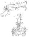
- FIG. 1is a perspective view of a portion of a vehicle seat depicting a seat track assembly in accordance with this invention.
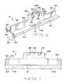
- FIG. 2is a perspective view of a portion of the seat track slide member in accordance with the invention.
- FIG. 3is a side elevation view of the portion of the track slide member illustrated in FIG. 2 .
- FIG. 4is a plan view of the portion of the track slide member illustrated in FIG. 2 .
- FIG. 5is a cross-sectional view of the track slide member taken along Lines 5 — 5 in FIG. 4 .
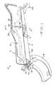
- FIG. 6is a partial cross-sectional view of the seat track assembly taken along Lines 6 — 6 in FIG. 1 .
- the seat track assembly 10generally includes an upper track member 12 , a lower track member 14 , and a slide member 16 disposed between the track members 12 and 14 for providing a generally low frictional sliding engagement therebetween, as will be explained in detail below.
- the seat track assembly 10provides fore and aft directional adjustment for a vehicle seat (not shown) relative to the floor of the vehicle in which the seat track assembly 10 is installed.
- the vehicle seathas a pair of seat track assemblies 10 , one for each side of the seat.
- the seatcan include a single seat track assembly 10 preferably located near the longitudinal center of the seat.
- the seat track assembly 10may be oriented in a position other than that shown in the figures. For example, as viewing FIG. 6 , the seat track assembly 10 could be oriented in a position 90 degrees offset from the position shown in FIG. 6 .
- the upper seat track member 12can be connected to a vehicle seat (not shown) by any conventional means.
- the upper seat track member 12can be connected to a seat bottom (not shown).
- the lower seat track 14can be fixed to the vehicle frame or floor (not shown) by any conventional means.
- the slide member 16is preferably fixed relative to the upper seat track member 12 such that sliding movement of the upper seat track member 12 causes the slide member 16 to move with the upper seat track member 12 .
- the means of fixing the slide member 16 with the upper seat track member 12is described in further detail below. Adjustment of the position of the vehicle seat by the occupant will generally cause the upper seat track member 12 to slide with the slide member 16 relative to the lower seat track member 14 .
- the seat track assembly 10could be configured such that the slide member 16 is fixed relative to the lower seat track member 14 .
- the lower seat track member 14has a pair of mounting structures or feet 18 , 20 , and 21 that are adapted to be connected to the vehicle frame. Any suitable mounting structures can be used for attaching the lower seat track member 14 to the vehicle.
- the lower seat track member 14is elongated and generally has a continuous cross-sectional shape. As best shown in FIG. 6 , the lower seat track member 14 includes a generally flat horizontally extending body portion 22 having a substantially flat sliding surface 24 . A pair of arms 26 extend upwardly from the ends of the body portion 22 .
- the arms 26preferably include upper portions 27 which are curved or for hook portions which cooperate with portions of the upper seat track member 12 to interlock the track members 12 and 14 so that they are restricted from pulling apart from one another when opposing vertical forces act on the members 12 and 14 , respectively, such as during a vehicle impact.
- the lower seat track member 14may include a plurality of slots 33 formed therein along the length of the body portion 22 for receiving fingers of a latch or lock mechanism (not shown) connected to the upper seat track member 12 for maintaining a locked relationship between the track members 12 and 14 .
- the upper seat track 12has a generally elongated shape and extends the length of the lower seat track member 14 .
- the upper seat track member 12is made of two shaped of stamped plates 28 and 30 , but can be formed in any suitable manner.
- the plates 28 , 30preferably are formed having mating portions 32 and spaced apart portions 34 .
- the plates 28 , 30are preferably joined about the mating portions 32 by any conventional means, such as welding or by fasteners.
- Each plate 28 , 30includes opposed recesses 36 formed therein.
- the recess 36can have any suitable shape, and the embodiment of the track assembly 10 illustrated in FIG. 1 discloses elongated arcuate shaped recess 36 which may receive other components of the seat (not shown).
- the recesses 36can be through holes or extend only partially through the side wall of the plates 28 , 30 .
- the recesses 36are adapted to receive a protrusion integrally formed on the slide member 16 for attaching the slide member 16 to the upper seat track member 12 , as is described below.
- the spaced relationship of the spaced apart portions 34defines a recess 35 formed in the upper seat track member 12 .
- the recess 35is preferably shaped such that a portion of the slide member 16 can fit within the spaced portion 34 , and more preferably fits in a snug or frictional fit.
- the upper seat track member 12can have any suitable configuration, such as a single unitary component having a groove formed therein to define the recess 35 .
- Each end of the spaced portions 34 of the upper track member 12has a horizontally extending flanged portion 40 including a pair of upwardly curved arms 41 that are received in hook portions of the upper portions 27 of the lower seat track member 14 to interlock the track members 12 and 14 .
- the flanged portions 40 of the upper track member 12define contact surfaces 43 that generally abut the slide member 16 , as will be described further below.
- the slide member 16disposed between the track members 12 and 14 .
- the slide member 16has a longitudinally extending strip or base portion 46 disposed between the body portion 22 and arms 26 of the lower seat track member 14 and the flanged portions 40 of the upper seat track member 12 .
- the slide member 16further includes a flange portion 42 extending generally vertically and perpendicularly from and upper surface of the base portion 46 .
- the slide member 16generally has an inverted T-shaped cross-section defined by the base portion 46 and the flange portion 42 .
- the flange portion 42separates the upper surface of the base portion 46 into a pair of contacting surfaces 47 one on either side of the flange portion 42 .
- the contacting surfaces 47 of the flange portion 42contact and abut against the contact surfaces 43 of the upper seat track member 12 . Since the slide member 16 is preferably fixed relative to the upper seat track member 12 , the contact surfaces 43 and 47 are generally fixed relative to one another. Generally, vertically oriented forces imparted on the upper seat track member 12 will be transmitted to the slide member 16 via the contact surfaces 43 and 47 .
- a stepped portion 48Extending upwardly from the flange portion 42 about a centrally located region of the slide member 16 is a stepped portion 48 , the reason for which will be explained below.
- a sliding surface 44Located on the bottom of the base portion 46 , is a sliding surface 44 .
- the sliding surface 44is the surface that slidingly engages the sliding surface 24 of the lower track member 14 for sliding movement therewith.
- the bottom of the body portion 46 of the slide member 16preferably is shaped such that the sliding surface 44 has a pair of longitudinally extending feet 50 that establish a pair of sliding surfaces with the sliding surface 24 of the lower track member 14 .
- the feet 50define a space 52 between each other such that the pair of sliding surfaces 44 have a reduced surface area thereby reducing the amount of friction that the two bearing or sliding surfaces 44 and 24 have with each other. Such a design also causes less material to be used for the sliding member 16 , thereby reducing the cost of the apparatus 10 .
- the longitudinal portions of each foot 50also have cut-out areas 54 , as best shown in FIGS. 3 and 5 , to even further reduce the frictional contact area between the sliding member 16 and the lower seat track member 14 .
- vertically oriented forces imparted on the lower seat track member 14will be transmitted to the slide member 16 via the sliding surfaces 24 and 44 .
- the components of the seat track assembly 10can be made of any suitable materials which provide sufficient strength to support the seat and permit relatively easy fore and aft adjustment.
- the upper and lower seat track members 12 and 14are made of metal, such as steel, and can be formed from shaped or stamped sheets.
- the sliding member 16is preferably made of plastic or other suitable material having a relatively low friction of coefficient to reduce the frictional forces between the contact sliding surfaces 24 and 44 .
- the sliding member 16should be able to withstand a relatively high load of compressive forces acting thereon.
- separation forcesmay act on the seat track assembly 10 wherein one of the ends of the upper seat track member 12 is being compressed against the respective end of the lower seat track assembly 14 , and the other end of the upper seat track member 12 is being pulled away from the respective end of the lower seat track member 14 via the interlocking portions 27 and 41 .
- the configuration of the seat track assembly 10is such that the sliding member 16 generally takes only compressive forces during high load situations, and is therefore not under high tensile loads.
- the flange portion 42generally functions to retain the slide member 16 onto the upper seat track member 12 and not to absorb high tensile loads.
- the flange portion 42Extending generally perpendicularly from the center of the top of the base portion 46 is the flange portion 42 .
- the flange portion 42is disposed in the recess 35 of the upper seat track member 12 .
- the flange portion 42is longitudinally extending along the full length of the base portion 46 .
- the flange portion 42does not have to extend the full length of the base portion 46 in order for the invention to be operable.
- the flange portion 42preferably has a thickness that is relatively small versus the overall longitudinal length of the flange portion 42 .
- the flange portion 42extends upwardly from a mid-point of the contact surface 47 of the slide member 16 , thereby splitting the contact surface into a pair of contact surfaces located on either side of the flange portion 42 , as shown in FIG. 6 . It should be understood that the flange portion 42 can extend from a mid-point anywhere between the lateral edges of the base portion 46 , and does not have to be centrally located. Formed at spaced positions along the length of the flange portion 42 are a plurality of spurs 56 which may be defined by reduced areas therebetween. The spurs 56 are preferably designed to frictionally engage the inner surface of the joined plates 28 , 30 of the upper seat track member 12 . Additionally, the spurs 56 provide structural stability for the flange portion 42 against lateral forces on the flange surface.
- the stepped portion 48preferably directly engages the upper track member 12 , described below, to fix the slide member 16 to the upper seat track member 12 .
- the stepped portion 48can be of any design such that the stepped portion 48 frictionally or lockingly engages the upper seat track member 12 .
- a protrusion 38 on the stepped portion 48engages one of the recesses 36 on the upper seat track member 12 . It is further preferred that a pair of oppositely opposing protrusions 38 extend from both sides of the stepped portion 48 to engage a recesses 36 on both sides of the upper seat track 12 .
- protrusions 38 , 39there are a plurality of protrusions 38 , 39 extending from the stepped portion 48 such that any one of said protrusions 38 , 39 can engage the recesses 36 of the upper seat track 12 .
- the protrusions 38 or 39extend into the recesses 36 thereby preventing the stepped portion 48 and the remainder of the slide member 16 from moving relative to the upper seat track member 12 , thereby fixing the slide member 16 relative to the upper seat track member 12 .
- the protrusions 38 , 39can have any suitable complimentary shape for engaging the recesses 36 .
- the protrusions 38 , 39can include ramped portions 38 a and 39 a for ease of insertion of the stepped portion 48 into the recess 35 of the upper track
- the central area of the stepped portion 48further defines one or more recesses 60 formed in the upper surface therein, and specifically the recesses 60 are located in the spaces between the pairs of opposed protrusions 38 , 39 .
- the protrusions 38are shown in the deformed position by dashed lines in FIG. 6 . Once the protrusions 38 , 39 are positioned adjacent the recesses 36 , the protrusions 38 , 39 are free to deflect back to normal position within the recesses 36 .
- the slide member 16can be “snap-fit” and locked onto the upper seat track member 12 .
- the protrusions 38 , 39can be squeezed together towards and generally into a respective recess 60 and will springingly release to engage the recesses 36 of the upper seat track 12 .
- the protrusions 38 , 39therefore preferably are shaped to engage the recesses 36 of the upper seat track member 12 .
- one or more of the protrusions 38 , 39can also frictionally engage the inner surface of the plates 28 , 30 that form the walls of the recess 35 of the upper seat track member 12 .
- a first pair of protrusions 38engage the recesses 36 of the upper seat track member 12
- the second pair of protrusions 39frictionally engage the inner surface of the upper seat track member 12 .
- FIG. 3Shown in FIG. 3 , is a side elevation view of the slide member 16 of FIG. 2 .
- the recesses 60 of the stepped portion 48are shown by dashed lines indicated generally at 60 .
- the recesses 60can have any suitable shape and can be located at any suitable position relative to the protrusions 38 , 39 .
- the protrusions 38are located at the top of the stepped portion 48 , positioned about the recesses 60 of the stepped portion 48 .
- Shown in greater detailis the cut-out portion 52 between the opposed pair of feet 50 of the body portion 46 of the slide member 16 . Also shown, by hidden lines, are the cut-out areas 54 within the longitudinally extending feet 50 .
- FIG. 4Shown in FIG. 4 is a plan view of the slide member 16 .
- the cut-out areas 54 within the longitudinally extending feet 50can be seen as preferred elongated slots located on the base portion 46 of the slide member 16 .
- the slide member 16can be sized to extend the entire length of the upper and/or lower seat track members 12 and 14 , or can have a length which is shorter than the lengths of the upper and/or lower seat track members 12 and 14 and is preferably centrally positioned thereon.
- the seat track assembly 10includes a single slide member 16 .
- the term “single slide member” as used hereinshould be understood to mean a one piece unitary member, as viewed through a cross-section of the seat track assembly 10 , such as FIG. 6 . It will be appreciated that the slide member 16 can extend along the substantial entire length of the seat track or multiple “single” slide members can be positioned along the length of the seat track assembly 10 spaced apart from one another.
- the slide member 16may also include a pair of through slots 61 as best shown in FIGS. 2 and 6 for permitting various tools or components (not shown) of the seat access through the slide member 16 .
- the slots 61may also function as guide windows or tool access ports for ease of installation of the slide member 16 onto the upper seat track member 12 .
- the slots 61are shown adjacent the stepped portion 48 they can be located at any location along the length of the slide member 16 .
Landscapes
- Engineering & Computer Science (AREA)
- Aviation & Aerospace Engineering (AREA)
- Transportation (AREA)
- Mechanical Engineering (AREA)
- Seats For Vehicles (AREA)
Abstract
Description
Claims (20)
Priority Applications (1)
| Application Number | Priority Date | Filing Date | Title |
|---|---|---|---|
| US10/286,347US6886797B2 (en) | 2001-11-01 | 2002-11-01 | Seat track assembly |
Applications Claiming Priority (2)
| Application Number | Priority Date | Filing Date | Title |
|---|---|---|---|
| US33653601P | 2001-11-01 | 2001-11-01 | |
| US10/286,347US6886797B2 (en) | 2001-11-01 | 2002-11-01 | Seat track assembly |
Publications (2)
| Publication Number | Publication Date |
|---|---|
| US20040089785A1 US20040089785A1 (en) | 2004-05-13 |
| US6886797B2true US6886797B2 (en) | 2005-05-03 |
Family
ID=32233095
Family Applications (1)
| Application Number | Title | Priority Date | Filing Date |
|---|---|---|---|
| US10/286,347Expired - Fee RelatedUS6886797B2 (en) | 2001-11-01 | 2002-11-01 | Seat track assembly |
Country Status (1)
| Country | Link |
|---|---|
| US (1) | US6886797B2 (en) |
Cited By (10)
| Publication number | Priority date | Publication date | Assignee | Title |
|---|---|---|---|---|
| US20060124301A1 (en)* | 2004-12-15 | 2006-06-15 | Bj Services Company | Slow release scale inhibitor composites and methods of using the same |
| US20060261238A1 (en)* | 2005-04-18 | 2006-11-23 | Faurecia Sieges D'automobile | Runner for a motor vehicle seat, and a method of manufacturing such a runner |
| US7278869B1 (en) | 2007-02-16 | 2007-10-09 | Tyco Electronics Corporation | Confined envelope connector system |
| US20080164685A1 (en)* | 2007-01-05 | 2008-07-10 | Ford Global Technologies, Llc | Automotive vehicle seat system |
| US20080164739A1 (en)* | 2007-01-05 | 2008-07-10 | Ford Global Technologies, Llc | Automotive vehicle seat system |
| US20090051208A1 (en)* | 2006-02-27 | 2009-02-26 | Szybisty Robert J | Leaf Spring Track Latch |
| US20090102261A1 (en)* | 2007-10-22 | 2009-04-23 | Lear Corporation | Seat track assembly |
| US20120256074A1 (en)* | 2011-04-05 | 2012-10-11 | Faurecia Sièges d'Automobile | Spacer Piece and Section Piece for Slide Rail of Automotive Vehicle Seat |
| US20160144746A1 (en)* | 2014-11-26 | 2016-05-26 | Faurecia Sièges d'Automobile | System comprising a slide track for motor vehicle seat and a support intended for attachment thereto |
| US10046672B2 (en)* | 2014-08-11 | 2018-08-14 | Tf-Metal Co., Ltd. | Seat slide device for vehicle |
Families Citing this family (8)
| Publication number | Priority date | Publication date | Assignee | Title |
|---|---|---|---|---|
| EP1866178B8 (en)* | 2005-03-23 | 2018-04-18 | Milsco Manufacturing, a unit of Jason Incorporated | Seat mount with integrated adjustment |
| US9216673B2 (en) | 2008-03-05 | 2015-12-22 | Milsco Manufacturing Company, A Unit Of Jason Incorporated | Low profile seat position adjustment system |
| US8807508B2 (en)* | 2011-07-25 | 2014-08-19 | Brose Fahrzeugteile Gmbh & Co. Kg, Coburg | Seat raiser for spacing a seat rail from the vehicle floor |
| JP6284715B2 (en)* | 2013-06-20 | 2018-02-28 | トヨタ紡織株式会社 | Vehicle seat |
| US10518666B2 (en) | 2014-10-14 | 2019-12-31 | Saint-Gobain Performance Plastics Pampus Gmbh | Linear motion assemblies and bearings for use in linear motion assemblies |
| PL3206906T3 (en) | 2014-10-14 | 2020-06-01 | Saint-Gobain Performance Plastics Pampus Gmbh | RECTOLINE ASSEMBLY and SLIDING ELEMENT FOR USE IN A STRAIGHT MOTION UNIT |
| US10717373B2 (en) | 2016-06-27 | 2020-07-21 | Toyota Body Seiko Co., Ltd. | Seat slide device |
| CN112356745B (en)* | 2016-10-14 | 2022-08-05 | 丰田车体精工株式会社 | seat slide |
Citations (18)
| Publication number | Priority date | Publication date | Assignee | Title |
|---|---|---|---|---|
| US3930632A (en) | 1972-12-27 | 1976-01-06 | Nissan Motor Company Limited | Adjustable seat assembly |
| US4088378A (en) | 1976-01-14 | 1978-05-09 | H. R. Turner (Willenhall) Ltd. | Seat slide including resiliently deformable element |
| US4487459A (en)* | 1983-07-01 | 1984-12-11 | General Motors Corporation | Seat slide structure |
| US4556186A (en)* | 1983-08-15 | 1985-12-03 | General Motors Corporation | Seat adjuster |
| US4811925A (en)* | 1986-06-23 | 1989-03-14 | Tachi-S Co. Ltd. | Slide rail |
| US4949931A (en) | 1988-09-17 | 1990-08-21 | Ikeda Bussan Company, Ltd. | Apparatus for mounting and modifying the arrangement of seats in a vehicle |
| US5213300A (en) | 1991-12-17 | 1993-05-25 | Itt Corporation | Extruded automotive seat track |
| US5445354A (en) | 1993-12-15 | 1995-08-29 | Itt Corporation | Track assembly for vehicle power seat adjuster |
| US5575564A (en) | 1995-05-26 | 1996-11-19 | Itt Automotive, Inc. | Seat track apparatus |
| US5575449A (en) | 1993-10-13 | 1996-11-19 | Tachi-S Co., Ltd. | Slide rail device for seat |
| US5741000A (en) | 1995-09-13 | 1998-04-21 | Atoma International, Inc. | Vehicle seat track assembly |
| US5746409A (en) | 1996-07-19 | 1998-05-05 | Excellence Manufacturing, Inc. | Reinforced seat track |
| US5876085A (en) | 1997-02-27 | 1999-03-02 | Milsco Manufacturing Company | Adjustable vehicle seat |
| US5915660A (en) | 1995-12-29 | 1999-06-29 | Fujikiko Kabushikikaisha | Seat slide apparatus |
| US6056257A (en) | 1997-06-17 | 2000-05-02 | Lear Corporation | Seat adjuster for a vehicle |
| US6105921A (en) | 1995-07-04 | 2000-08-22 | Henderson's Industries Pty. Ltd. | Adjustable seat mounting mechanism |
| US6234553B1 (en) | 1998-10-02 | 2001-05-22 | Johnson Controls Technology Company | Flexible seat system |
| US6499712B1 (en)* | 1999-02-03 | 2002-12-31 | Tecla Company, Inc. | Electric seat slide and actuator system |
- 2002
- 2002-11-01USUS10/286,347patent/US6886797B2/ennot_activeExpired - Fee Related
Patent Citations (18)
| Publication number | Priority date | Publication date | Assignee | Title |
|---|---|---|---|---|
| US3930632A (en) | 1972-12-27 | 1976-01-06 | Nissan Motor Company Limited | Adjustable seat assembly |
| US4088378A (en) | 1976-01-14 | 1978-05-09 | H. R. Turner (Willenhall) Ltd. | Seat slide including resiliently deformable element |
| US4487459A (en)* | 1983-07-01 | 1984-12-11 | General Motors Corporation | Seat slide structure |
| US4556186A (en)* | 1983-08-15 | 1985-12-03 | General Motors Corporation | Seat adjuster |
| US4811925A (en)* | 1986-06-23 | 1989-03-14 | Tachi-S Co. Ltd. | Slide rail |
| US4949931A (en) | 1988-09-17 | 1990-08-21 | Ikeda Bussan Company, Ltd. | Apparatus for mounting and modifying the arrangement of seats in a vehicle |
| US5213300A (en) | 1991-12-17 | 1993-05-25 | Itt Corporation | Extruded automotive seat track |
| US5575449A (en) | 1993-10-13 | 1996-11-19 | Tachi-S Co., Ltd. | Slide rail device for seat |
| US5445354A (en) | 1993-12-15 | 1995-08-29 | Itt Corporation | Track assembly for vehicle power seat adjuster |
| US5575564A (en) | 1995-05-26 | 1996-11-19 | Itt Automotive, Inc. | Seat track apparatus |
| US6105921A (en) | 1995-07-04 | 2000-08-22 | Henderson's Industries Pty. Ltd. | Adjustable seat mounting mechanism |
| US5741000A (en) | 1995-09-13 | 1998-04-21 | Atoma International, Inc. | Vehicle seat track assembly |
| US5915660A (en) | 1995-12-29 | 1999-06-29 | Fujikiko Kabushikikaisha | Seat slide apparatus |
| US5746409A (en) | 1996-07-19 | 1998-05-05 | Excellence Manufacturing, Inc. | Reinforced seat track |
| US5876085A (en) | 1997-02-27 | 1999-03-02 | Milsco Manufacturing Company | Adjustable vehicle seat |
| US6056257A (en) | 1997-06-17 | 2000-05-02 | Lear Corporation | Seat adjuster for a vehicle |
| US6234553B1 (en) | 1998-10-02 | 2001-05-22 | Johnson Controls Technology Company | Flexible seat system |
| US6499712B1 (en)* | 1999-02-03 | 2002-12-31 | Tecla Company, Inc. | Electric seat slide and actuator system |
Cited By (19)
| Publication number | Priority date | Publication date | Assignee | Title |
|---|---|---|---|---|
| US20060124301A1 (en)* | 2004-12-15 | 2006-06-15 | Bj Services Company | Slow release scale inhibitor composites and methods of using the same |
| US20060261238A1 (en)* | 2005-04-18 | 2006-11-23 | Faurecia Sieges D'automobile | Runner for a motor vehicle seat, and a method of manufacturing such a runner |
| US8146877B2 (en)* | 2005-04-18 | 2012-04-03 | Faurecia Sièges d'Automobile | Runner for a motor vehicle seat, and a method of manufacturing such a runner |
| US20090051208A1 (en)* | 2006-02-27 | 2009-02-26 | Szybisty Robert J | Leaf Spring Track Latch |
| US20080164739A1 (en)* | 2007-01-05 | 2008-07-10 | Ford Global Technologies, Llc | Automotive vehicle seat system |
| US8628135B2 (en)* | 2007-01-05 | 2014-01-14 | Ford Global Technologies, Llc | Automotive vehicle seat system |
| CN101214798B (en)* | 2007-01-05 | 2012-07-18 | 福特全球技术公司 | Automotive vehicle seat system |
| US9010865B2 (en) | 2007-01-05 | 2015-04-21 | Ford Global Technologies, Llc | Automotive vehicle seat system |
| US20080164685A1 (en)* | 2007-01-05 | 2008-07-10 | Ford Global Technologies, Llc | Automotive vehicle seat system |
| US7278869B1 (en) | 2007-02-16 | 2007-10-09 | Tyco Electronics Corporation | Confined envelope connector system |
| US20090102261A1 (en)* | 2007-10-22 | 2009-04-23 | Lear Corporation | Seat track assembly |
| US8052111B2 (en) | 2007-10-22 | 2011-11-08 | Lear Corporation | Seat track assembly |
| CN103358941A (en)* | 2011-04-05 | 2013-10-23 | 佛吉亚汽车座椅公司 | Spacer piece and section piece for slide rail of automotive vehicle seat |
| US20120256074A1 (en)* | 2011-04-05 | 2012-10-11 | Faurecia Sièges d'Automobile | Spacer Piece and Section Piece for Slide Rail of Automotive Vehicle Seat |
| US9511686B2 (en)* | 2011-04-05 | 2016-12-06 | Faurecia Sieges D'automobile | Spacer piece and section piece for slide rail of automotive vehicle seat |
| CN103358941B (en)* | 2011-04-05 | 2017-09-12 | 佛吉亚汽车座椅公司 | The cushion block and locking nub of Seat slide for motor vehicle |
| US10046672B2 (en)* | 2014-08-11 | 2018-08-14 | Tf-Metal Co., Ltd. | Seat slide device for vehicle |
| US20160144746A1 (en)* | 2014-11-26 | 2016-05-26 | Faurecia Sièges d'Automobile | System comprising a slide track for motor vehicle seat and a support intended for attachment thereto |
| US9834116B2 (en)* | 2014-11-26 | 2017-12-05 | Faurecia Sièges d'Automobile | System comprising a slide track for motor vehicle seat and a support intended for attachment thereto |
Also Published As
| Publication number | Publication date |
|---|---|
| US20040089785A1 (en) | 2004-05-13 |
Similar Documents
| Publication | Publication Date | Title |
|---|---|---|
| US6886797B2 (en) | Seat track assembly | |
| US8646742B2 (en) | Seat rail device | |
| US4483504A (en) | Slide rail assemblies | |
| US8282151B2 (en) | Vehicle seat slide device | |
| EP0705178B1 (en) | Seat slide device | |
| US7314204B2 (en) | Sliding rail system | |
| US10703227B2 (en) | Seat sliding device | |
| US6176460B1 (en) | Seat sliding apparatus for a vehicle | |
| US4725032A (en) | Seat slide adjuster for vehicles | |
| US20030094558A1 (en) | Seat slide device | |
| EP0617675A1 (en) | Extruded automotive seat track | |
| JP2018095152A (en) | Slide rail support structure | |
| EP2292462A1 (en) | Slide Structure of Vehicle Seat | |
| US5575564A (en) | Seat track apparatus | |
| US5842383A (en) | Seat slide mechanism for vehicles | |
| US20220402405A1 (en) | Slide rail locking system with continuous adjustment | |
| JPH0635765Y2 (en) | Vehicle seat rails | |
| US5219230A (en) | Vehicle seat slides | |
| KR20040073399A (en) | A track assembly for a motor vehicle seat, and a seat equipped with such a track assembly | |
| KR102450017B1 (en) | Sliding type carrier for motorcycle | |
| US4392692A (en) | Seat support slide track structure | |
| US5720463A (en) | Automotive seat rail mechanism | |
| JP3044089B2 (en) | Seat slide device | |
| US20050285005A1 (en) | Automotive seat track having vertically adjustable bearings | |
| JPH0723072B2 (en) | Vehicle seat slider |
Legal Events
| Date | Code | Title | Description |
|---|---|---|---|
| AS | Assignment | Owner name:LEAR CORPORATION, MICHIGAN Free format text:ASSIGNMENT OF ASSIGNORS INTEREST;ASSIGNORS:MCCULLEN, KEITH;HENSLEY, KEITH;GAGE, RANDY;AND OTHERS;REEL/FRAME:013624/0030;SIGNING DATES FROM 20021114 TO 20021125 | |
| CC | Certificate of correction | ||
| AS | Assignment | Owner name:JPMORGAN CHASE BANK, N.A., AS GENERAL ADMINISTRATI Free format text:SECURITY AGREEMENT;ASSIGNOR:LEAR CORPORATION;REEL/FRAME:017858/0719 Effective date:20060425 | |
| FPAY | Fee payment | Year of fee payment:4 | |
| AS | Assignment | Owner name:JPMORGAN CHASE BANK, N.A., AS ADMINISTRATIVE AGENT Free format text:GRANT OF FIRST LIEN SECURITY INTEREST IN PATENT RIGHTS;ASSIGNOR:LEAR CORPORATION;REEL/FRAME:023519/0267 Effective date:20091109 Owner name:JPMORGAN CHASE BANK, N.A., AS ADMINISTRATIVE AGENT Free format text:GRANT OF SECOND LIEN SECURITY INTEREST IN PATENT RIGHTS;ASSIGNOR:LEAR CORPORATION;REEL/FRAME:023519/0626 Effective date:20091109 | |
| FPAY | Fee payment | Year of fee payment:8 | |
| AS | Assignment | Owner name:JPMORGAN CAHSE BANK, N.A., AS AGENT, ILLINOIS Free format text:SECURITY INTEREST;ASSIGNOR:LEAR CORPORATION;REEL/FRAME:030076/0016 Effective date:20130130 Owner name:JPMORGAN CHASE BANK, N.A., AS AGENT, ILLINOIS Free format text:SECURITY INTEREST;ASSIGNOR:LEAR CORPORATION;REEL/FRAME:030076/0016 Effective date:20130130 | |
| AS | Assignment | Owner name:LEAR CORPORATION, MICHIGAN Free format text:RELEASE BY SECURED PARTY;ASSIGNOR:JPMORGAN CHASE BANK, N.A.;REEL/FRAME:032722/0553 Effective date:20100830 | |
| AS | Assignment | Owner name:LEAR CORPORATION, MICHIGAN Free format text:RELEASE BY SECURED PARTY;ASSIGNOR:JPMORGAN CHASE BANK, N.A.;REEL/FRAME:032770/0843 Effective date:20100830 | |
| AS | Assignment | Owner name:LEAR CORPORATION, MICHIGAN Free format text:RELEASE BY SECURED PARTY;ASSIGNOR:JPMORGAN CHASE BANK, N.A., AS AGENT;REEL/FRAME:037701/0180 Effective date:20160104 Owner name:LEAR CORPORATION, MICHIGAN Free format text:RELEASE BY SECURED PARTY;ASSIGNOR:JPMORGAN CHASE BANK, N.A., AS AGENT;REEL/FRAME:037701/0340 Effective date:20160104 Owner name:LEAR CORPORATION, MICHIGAN Free format text:RELEASE BY SECURED PARTY;ASSIGNOR:JPMORGAN CHASE BANK, N.A., AS AGENT;REEL/FRAME:037701/0251 Effective date:20160104 | |
| AS | Assignment | Owner name:LEAR CORPORATION, MICHIGAN Free format text:RELEASE BY SECURED PARTY;ASSIGNOR:JPMORGAN CHASE BANK, N.A., AS AGENT;REEL/FRAME:037702/0911 Effective date:20160104 Owner name:LEAR CORPORATION, MICHIGAN Free format text:RELEASE BY SECURED PARTY;ASSIGNOR:JPMORGAN CHASE BANK, N.A., AS AGENT;REEL/FRAME:037731/0918 Effective date:20160104 | |
| REMI | Maintenance fee reminder mailed | ||
| LAPS | Lapse for failure to pay maintenance fees | ||
| STCH | Information on status: patent discontinuation | Free format text:PATENT EXPIRED DUE TO NONPAYMENT OF MAINTENANCE FEES UNDER 37 CFR 1.362 | |
| FP | Lapsed due to failure to pay maintenance fee | Effective date:20170503 |