US6886710B2 - Stackable tray having anti-pivot stop and wash apertures - Google Patents
Stackable tray having anti-pivot stop and wash aperturesDownload PDFInfo
- Publication number
- US6886710B2 US6886710B2US10/174,698US17469802AUS6886710B2US 6886710 B2US6886710 B2US 6886710B2US 17469802 AUS17469802 AUS 17469802AUS 6886710 B2US6886710 B2US 6886710B2
- Authority
- US
- United States
- Prior art keywords
- tray
- wall
- sides
- apron
- foot
- Prior art date
- Legal status (The legal status is an assumption and is not a legal conclusion. Google has not performed a legal analysis and makes no representation as to the accuracy of the status listed.)
- Ceased, expires
Links
- 239000012530fluidSubstances0.000claimsabstract2
- 238000004140cleaningMethods0.000abstractdescription5
- 239000000463materialSubstances0.000description4
- 230000013011matingEffects0.000description2
- 230000004048modificationEffects0.000description2
- 238000012986modificationMethods0.000description2
- 230000004044responseEffects0.000description2
- 230000008901benefitEffects0.000description1
- 230000003247decreasing effectEffects0.000description1
- 238000001746injection mouldingMethods0.000description1
- 230000003993interactionEffects0.000description1
Images


Classifications
- B—PERFORMING OPERATIONS; TRANSPORTING
- B65—CONVEYING; PACKING; STORING; HANDLING THIN OR FILAMENTARY MATERIAL
- B65D—CONTAINERS FOR STORAGE OR TRANSPORT OF ARTICLES OR MATERIALS, e.g. BAGS, BARRELS, BOTTLES, BOXES, CANS, CARTONS, CRATES, DRUMS, JARS, TANKS, HOPPERS, FORWARDING CONTAINERS; ACCESSORIES, CLOSURES, OR FITTINGS THEREFOR; PACKAGING ELEMENTS; PACKAGES
- B65D21/00—Nestable, stackable or joinable containers; Containers of variable capacity
- B65D21/02—Containers specially shaped, or provided with fittings or attachments, to facilitate nesting, stacking, or joining together
- B65D21/04—Open-ended containers shaped to be nested when empty and to be superposed when full
- B65D21/043—Identical stackable containers specially adapted for nesting after rotation around a vertical axis
- B65D21/046—Identical stackable containers specially adapted for nesting after rotation around a vertical axis about 90°
- B—PERFORMING OPERATIONS; TRANSPORTING
- B65—CONVEYING; PACKING; STORING; HANDLING THIN OR FILAMENTARY MATERIAL
- B65D—CONTAINERS FOR STORAGE OR TRANSPORT OF ARTICLES OR MATERIALS, e.g. BAGS, BARRELS, BOTTLES, BOXES, CANS, CARTONS, CRATES, DRUMS, JARS, TANKS, HOPPERS, FORWARDING CONTAINERS; ACCESSORIES, CLOSURES, OR FITTINGS THEREFOR; PACKAGING ELEMENTS; PACKAGES
- B65D21/00—Nestable, stackable or joinable containers; Containers of variable capacity
- B65D21/02—Containers specially shaped, or provided with fittings or attachments, to facilitate nesting, stacking, or joining together
- B65D21/04—Open-ended containers shaped to be nested when empty and to be superposed when full
- B65D21/043—Identical stackable containers specially adapted for nesting after rotation around a vertical axis
- B65D21/045—Identical stackable containers specially adapted for nesting after rotation around a vertical axis about 180° only
- B—PERFORMING OPERATIONS; TRANSPORTING
- B65—CONVEYING; PACKING; STORING; HANDLING THIN OR FILAMENTARY MATERIAL
- B65D—CONTAINERS FOR STORAGE OR TRANSPORT OF ARTICLES OR MATERIALS, e.g. BAGS, BARRELS, BOTTLES, BOXES, CANS, CARTONS, CRATES, DRUMS, JARS, TANKS, HOPPERS, FORWARDING CONTAINERS; ACCESSORIES, CLOSURES, OR FITTINGS THEREFOR; PACKAGING ELEMENTS; PACKAGES
- B65D81/00—Containers, packaging elements, or packages, for contents presenting particular transport or storage problems, or adapted to be used for non-packaging purposes after removal of contents
- B65D81/24—Adaptations for preventing deterioration or decay of contents; Applications to the container or packaging material of food preservatives, fungicides, pesticides or animal repellants
- B65D81/26—Adaptations for preventing deterioration or decay of contents; Applications to the container or packaging material of food preservatives, fungicides, pesticides or animal repellants with provision for draining away, or absorbing, or removing by ventilation, fluids, e.g. exuded by contents; Applications of corrosion inhibitors or desiccators
- B65D81/261—Adaptations for preventing deterioration or decay of contents; Applications to the container or packaging material of food preservatives, fungicides, pesticides or animal repellants with provision for draining away, or absorbing, or removing by ventilation, fluids, e.g. exuded by contents; Applications of corrosion inhibitors or desiccators for draining or collecting liquids without absorbing them
Definitions
- This inventiongenerally relates to multi-purpose reusable load-bearing trays and, more specifically, to trays adapted to be nestable or stackable in three positions.
- Plastic trays that are stackable and/or nestablecan be desirable to maintain cargo such as material and/or products.
- existing traysare not as efficient as desired. Specifically, existing trays can require excessive handling time and cleaning time. Also, the existing trays may not nest together as well as desired. An improved tray is needed.
- the present inventionprovides an improved tray for maintaining cargo during transport.
- the tray of the present inventioncan include one or more drain apertures disposed along a front or back of the tray.
- the drain aperturecan improve the efficiency of the tray by improving the cleaning of the tray.
- the structure of the existing trayscan define blind holes and pockets in which debris and/or vermin can accumulate. Positioning a drain aperture adjacent the blind holes or pockets of the tray can enhance the likelihood that the debris can be quickly removed during cleaning.
- the drain aperturecan be disposed along any surface of the front or back of the tray and can be defined, at least in part, by ribs disposed between a wall and an apron of the front or back of the tray.
- the ribscan be any shape as desired, including arcuate, straight, cross-shaped, or T-shaped.
- a drain aperturecan also be formed in a notch defined in the front or back of the tray; the notch being used for aligning two trays during stacking.
- the present inventionalso provides a tray with a domed bottom.
- the bottom of the traycan be convex with respect to the interior of the tray.
- the domed shape of the bottom of the traycan enhance the strength of the tray.
- the bottomcan also include at least one transverse and/or at least one longitudinal rib to enhance the strength of the bottom.
- the bottomcan be formed with a convex or concave profile.
- the present inventionalso provides a tray with two handles where one of the handles includes a gripping portion.
- one of the handlesincludes a gripping portion.
- the present inventionalso provides ribs disposed in a pocket of a bottom tray for receiving and engaging feet of a top tray.
- the ribscan enhance the alignment of two trays stacked relative to each other and support a top tray during sliding movement relative to a bottom tray.
- a rib closest to the center of the traycan be tapered to reduce the likelihood that a top tray will bind relative to a bottom tray when the two trays are being engaged.
- the present inventionalso provides a stop having a ramp shape positionable in a channel of the tray.
- a stophaving a ramp shape positionable in a channel of the tray.
- the top trayis slidingly received by a channel of the bottom tray.
- the stop disposed in the channelcan limit the movement of the top tray relative to the bottom tray when the trays are being engaged with respect to one another.
- a ramped portion of the stopcan enhance the efficiency of the tray by ensuring that sliding movement of the trays will only be prevented in only one direction.
- the present inventionalso provides a tray having beams disposed on a front of the tray and corresponding slots formed in the rear of the tray.
- the corresponding beams and slotscan permit two trays to be stacked on top of one another when in a similar orientation.
- the support of the top tray relative to the bottom tray, when two trays are stacked in similar orientation,does not occur at the outermost edges of the front corners of the trays.
- the beamscan be received by the slots when two trays are stacked in an opposite direction relative to one another.
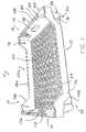
- FIG. 1is a perspective view of a tray according to a first embodiment of the invention
- FIG. 2is a cross-sectional view of a front of the tray according to the first embodiment of the invention
- FIG. 3is a top plan view of the tray according to the first embodiment of the invention.
- FIG. 4is a partial cross-sectional and perspective view of the tray according to the first embodiment of the invention showing the configuration of ribs between the wall and the apron;
- FIG. 5is a detailed partial perspective view of a front corner of the tray according to the first embodiment of the invention.
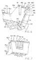
- FIG. 6is a partial detailed perspective view of a rear corner of the tray according to the first embodiment of the invention.
- FIG. 7is partial detailed perspective view of the rear corner of the tray according to the first embodiment of the invention.
- FIG. 8is a detailed top plan view of a second side of the tray according to the first embodiment of the invention.
- FIG. 9is a detailed perspective view of a rear corner of a tray according to the first embodiment of the invention.
- FIG. 10is a front plan view of two trays according to the first embodiment of the invention stacked in a similar orientation with respect to one another;
- FIG. 11is a rear plan view of two trays according to the first embodiment of the invention stacked at an angle of 90° relative to one another;
- FIG. 12is a rear plan view of two trays according to the first embodiment of the invention stacked at an angle of 180° relative to one another;
- FIG. 13is a side plan view of two trays according to the first embodiment of the invention stacked in a similar orientation with respect to one another;
- FIG. 14is a side plan view of two trays according to the first embodiment of the invention stacked at an angle of 180° relative to one another;
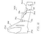
- FIG. 15is a perspective view of a tray according to a second embodiment of the invention.
- FIG. 16is a detailed partial cross-sectional view of a front of the tray according to the second embodiment of the invention showing the ribs;
- FIG. 17is a top plan view of the tray according to the second embodiment of the invention.
- FIG. 18is a partial detailed view of the front corners of two trays according to the second embodiment of the invention.
- FIG. 19is a partial detailed view of a rear corner of the tray according to the second embodiment of the invention.
- FIG. 20is a front plan view of two trays according to the second embodiment of the invention stacked in a similar orientation with respect to one another;
- FIG. 21is a plan view of two trays according to the second embodiment stacked at an angle of 180° relative to one another;
- FIG. 22is a side plan view of two trays according to the second embodiment of the invention stacked in a similar orientation with respect to one another;
- FIG. 23is a side plan view of two trays according to the second embodiment of the invention stacked at an angle of 180° relative to one another;
- FIG. 24is a front plan view of two trays according to the second embodiment of the invention stacked at an angle of 90° relative to one another;
- FIG. 25is a schematic view of a tray according to the invention having a domed bottom.
- the present inventionprovides a multipurpose tray 10 .
- the tray 10can include a front 12 , a rear 14 , a first side 16 , a second side 18 , and a bottom 20 which can be integrally formed with respect to one another.
- the tray 10can be fabricated from plastic in an injection molding process.
- FIG. 15shows another embodiment of the invention, a tray 10 a having a front 12 a, a rear 14 a, a first side 16 a, a second side 18 a, and a bottom 20 a which can be integrally formed with respect to one another.
- the front 12can extend from the first side 16 to the second side 18 and can include a wall 22 , a fillet 24 and an apron 26 .
- the wall 22 , fillet 24 and apron 26can define a channel 28 .
- the front 12can also include a right-hand portion 30 and a left-hand portion 32 which are mirror images of one another with respect to a substantially vertical center axis 186 of the front 12 , as best seen in FIG. 10 .
- the fillet 24can define an opening 34 .
- the opening 34can be centered along the axis 186 of the front 12 with respect to the right-hand portion 30 and the left-hand portion 32 .
- the opening 34can include a bottom surface 36 and side surfaces 38 and 40 .
- an opening 34 ais shown in perspective view in FIG. 15 , in partial detailed cross-sectional view in FIG. 16 , and in overhead plan view in FIG. 17 .
- the opening 34 acan be defined by a fillet 24 a of a front 12 a of tray 10 a.
- the opening 34 acan include bottom surface 36 a, side surfaces 38 a and 40 a as well as secondary bottom surfaces 36 b and 36 c and secondary side surfaces 38 b and 40 b.
- the fillet 24can also define a boss 42 , a notch 44 , a gain 46 , and a dimple 48 .
- the boss 42is positioned along the length of the front 12 between the opening 34 and the notch 44 .
- the boss 42includes a support surface 50 .
- a projection 52can extend from the fillet 24 between the notch 44 and the gain 46 .
- the dimple 48can be positioned at an outermost edge of the front 12 .
- An alternative embodiment of the dimple 48 ais shown extending a height of an apron 26 a of the tray 10 a in FIGS. 17 , 18 and 20 .
- fillet 24can be pierced by one or more apertures 54 .
- a plurality of apertures 54can be evenly spaced along the length of the front 12 .
- the apertures 54can be formed in the bottom surface 36 of the opening 34 , the side surfaces 38 and 40 of the opening 34 , or in the notch 44 .
- the apertures 54can enhance cleaning of the tray 10 by reducing the likelihood that vermin or debris will become trapped in the channel 28 .
- ribscan be disposed in the channel 28 to define a plurality of apertures and to enhance the structural integrity of the tray 10 .
- ribs 56 , 58 , 60 and 62can be formed in various shapes and be disposed at various positions relative to the opening 34 .
- ribs 64 , 66 , 68 and 70can be positioned adjacent a side surface 38 a, a secondary bottom surface 36 b and a bottom surface 36 a or any combination thereof.
- the front 12also includes a wall 22 .
- the wall 22can define a foot 72 and shoulder 74 .
- the foot 72can be shaped to correspond to the shape of the notch 44 .
- the foot 72is substantially vertically aligned with the notch 44 .
- the shoulder 74will be described in greater detail below.
- FIG. 18shows a front wall 12 a of a tray 10 a having wall 22 a that defines a foot 72 a and shoulder 74 a.
- the foot 72 ais shaped to correspond to the shape of the notch 44 a and is substantially vertically aligned with the notch 44 a.
- a beam 76extends from wall 22 generally toward the apron 26 .
- the beam 76does not extend past the apron 26 .
- the beam 76can be tapered such that the beam 76 is narrowest immediately adjacent the foot 72 .
- the beam 76is substantially vertically aligned with the support surface 50 .
- FIG. 18shows a front 12 a having a beam 76 a substantially vertically aligned with the support surface 50 a of a boss 42 a.
- the rear 14 of the tray 10can be substantially similar to the front 12 of the tray 10 .
- the rear 14can include a wall 22 b, a fillet 24 b, and an apron 26 b.
- the fillet 24 bcan define an opening 34 b, including bottom surface 36 d and side surfaces 38 c and 40 c, and a boss 42 b.
- One or more apertures 54can pierce the fillet 24 b along the surface 36 d, or a notch 44 b.
- the rear 14also includes a slot 78 .
- the slot 78extends vertically downward from the boss 42 b along the wall 22 b.
- the slot 78can be tapered to be narrowest at a position furthest from the boss 42 b.
- the slot 78is substantially aligned with the beam 76 of the front 12 to receive a beam 76 when two trays 10 are stacked 180° relative to another. The stacking of two trays relative to one another will be described in greater detail below.
- the rear 14does not include beams extending from the wall 22 b as best seen in FIG. 9 . Also, the rear 14 may not include a dimple 28 as formed in the front 12 .
- FIGS. 15 and 19show the rear 14 a of alternative embodiment of the invention.
- the rear 14 acan be substantially similar to the front 12 a of the tray 10 a.
- the rear 14 acan include a wall 22 c, a fillet 24 c, and an apron 26 c.
- the fillet 24 ccan define an opening 34 c, including bottom surfaces 36 e, 36 f and 36 g as well as side surfaces 38 d, 38 e and 40 d, 40 e and a boss 42 c.
- One or more apertures 54can pierce the fillet 24 c along the surfaces 36 e, 36 f, 36 g, 38 d, 38 e, 40 d and 40 e, or a notch 44 c.
- the rear 14 aalso includes a slot 78 a.
- the slot 78 aextends vertically downward from the boss 42 c along the wall 22 c.
- the slot 78 acan be tapered to be narrowest at a position furthest from the boss 42 c.
- the slot 78 ais substantially aligned with the beam 76 a of the front 12 a to receive a beam 76 a when two trays 10 a are stacked 180° relative to another. The stacking of two trays relative to one another will be described in greater detail below.
- the rear 14 adoes not include beams extending from the wall 22 c as best seen in FIG. 15 . Also, the rear 14 a may not include a dimple 28 a as formed in the front 12 a.
- the second side 18can include an inner face 80 , an outer face 82 , a top portion 84 and a bottom portion 86 .
- the inner face 80can be defined by an innermost surface 88 , a front pocket 90 and a rear pocket 92 .
- the front and rear pockets 90 and 92can be defined by inwardly facing surfaces 96 and 98 , front facing surfaces 100 and 102 , rear facing surfaces 104 and 106 , and upper facing surfaces 108 and 109 , respectively.
- the inwardly facing surfaces, the front facing surfaces, the rear facing surfaces and the upper facing surfaces of each pocketdefine openings 110 and 112 in the front and rear pockets 90 and 92 .
- the pockets 90 and 92are shaped to substantially correspond to the shape of mating feet disposed on the outer face 82 of the second side 18 . The feet will be described in greater detail below.
- one or more ribs 114can be disposed on the inwardly facing surface 98 of the rear pocket 92 .
- the ribs 114are generally arcuate or semi-circular in cross section.
- a rib 116 positioned closest to the center of the second side 18can be tapered, such that a radius of the rib 116 is greater than a radius of the ribs 114 .
- the rib 116 and ribs 114can project from the surface 98 the same distance. Tapering the rib 116 and enhances the sliding interaction between two trays 10 to be stacked relative to one another. Specifically, it has been found that when the rib 116 is shaped without a tapered semi-circular cross section, a top tray sliding relative to a bottom tray can bind.
- the outer face 82 of the second side 18can include a honeycomb section 118 , a front foot 120 and a rear foot 122 , and an outwardly facing surface 124 .
- the honeycomb section 118can be disposed adjacent to the top portion 84 of the second side 18 .
- the honeycomb section 118enhances the strength and rigidity of the tray 10 .
- a planar surface 126is disposed on the outer face 82 .
- Numerical and alphabetic informationcan be molded or formed on the surface 126 .
- Runners 128 and 130extend downwardly toward the bottom portion 86 from the honeycomb section 118 .
- the front foot 120 and a rear foot 122extend from the outwardly facing surface 124 of the outer face 82 .
- the feet 120 and 122include runners 132 and 134 respectively.
- the feet 120 and 122can be honeycombed.
- the front foot 120is shaped to correspond to the shape of the rear pocket 92 .
- the rear foot 122is shaped to correspond to the shape of the front pocket 90 .
- the front foot 120can be defined in part by an outer surface or plane 136 , best seen in FIG. 5 .
- the rear foot 122can be defined by two outer surfaces or planes 138 and 140 .
- the surfaces 138 and 140are disposed at an angle of greater than 0° relative to one another.
- the top portion 84 of the second side 18is defined by a plurality of upper facing surfaces 142 , 144 , 146 , 148 , 150 , 152 , 154 , and 156 .
- Surfaces 144 and 148are downwardly recessed with respect to surface 142 .
- Surfaces 142 , 146 and 150are substantially co-planar.
- Surfaces 152 , 154 and 156define the bottom surface of a discontinuous channel 158 extending along the top portion 84 of the second side 18 between the front 12 and the rear 14 .
- the channel 158is longitudinally aligned with the gain 46 of the front 12 and a gain 46 a of the rear 14 .
- a stop 160is disposed in the channel 158 .
- the stop 160can be shaped like a ramp with a substantially vertical side facing toward the front 12 and a substantially ramped side facing the rear 14 .
- the stop 160can prevent movement of a top tray relative to a bottom tray when two trays are to be stacked in a similar orientation and slidingly engaged in a first direction as will be discussed in greater detail below.
- the first directionis defined when the front of a top tray is engages the rear of the bottom tray at the beginning of the sliding engagement.
- the second directionis defined when the rear of the top tray is received by front of the bottom tray during the beginning of the sliding engagement.
- Surface 152is downwardly recessed with respect to surface 154 and a rounded shoulder 162 can be defined therebetween.
- the bottom portion 86 of the second side 18includes two longitudinal rails 164 and 166 that extend between opposite edges of the foot 72 of the front 12 to a foot 72 b of the rear 14 .
- Transverse rails 168can be randomly or evenly spaced between the rails 164 and 166 along the length of the second side 18 .
- the first side 16 and the second side 18are substantially mirror images of one another with respect to a longitudinal axis 190 .
- the sides 16 and 18are different in that a configuration of a handle 170 of the second section 18 is different than a configuration of a handle 172 of the first section 16 .
- one of the handles 170 and 172includes a gripping portion 174 .
- the gripping portionincludes one or more rounded projections extending into a cavity defined by the handle.
- FIGS. 1 and 3illustrate a gripping portion 174 having one rounded projection extending from handle portion 172 .
- the gripping portioncan extend from the handle portion 170 and can include more than one rounded projection.
- FIG. 15illustrates a gripping portion 174 a including a plurality of rounded projections.
- the gripping portions 174 and 174 agenerally conform to the hand of a user of the tray 10 or tray 10 a.
- the gripping portion 174can be advantageous to indicate to a human handler the orientation of the tray. For example, if the trays are to be stacked at 180° relative to one another, the human handler can grasp a tray to be stacked and recognize whether the tray can be placed on top of a stack of trays or must be oriented differently before the tray is stacked by feeling the gripping portion instead of having to examine the sides of the tray to identify the location of the beam 76 of the tray being held and the slot 78 of the tray at the top of the stack of trays.
- the human handlerwhen trays are to be stacked at 180° relative to one another, the human handler will recognize that every other tray must be grasped so that the gripping portion is felt with a particular hand. When the trays are to be stacked at 0° relative to one another, the human handler will recognize that every tray must be grasped so that the gripping portion is felt with a particular hand.
- the first side 16 a and second side 18 a of the tray 10 acan be substantially similar to the first side 16 and second side 18 of the tray 10 , respectively.
- the first side 16 a and second side 18 acan be mirror images of one another about a longitudinal axis 198 .
- Each sidecan include an inner face 80 a, an outer face 82 a, a top portion 84 a and a bottom portion 86 a.
- the inner face 80 acan be defined by an innermost surface 88 a, a front pocket 90 a and a rear pocket 92 a.
- the front and rear pockets 90 a and 92 acan be defined by inwardly facing surfaces 96 a and 98 a, front facing surfaces 100 a and 102 a, and rear facing surfaces 104 a and 106 a, respectively.
- the rear pocket 92 acan include an upper facing surface 109 a.
- the inwardly facing surfaces, the front facing surfaces, the rear facing surfaces and the upper facing surfaces of each pocketdefine openings 110 a and 112 a in the front and rear pockets 90 a and 92 a.
- the pockets 90 a and 92 aare shaped to substantially correspond to the shape of mating feet disposed on the outer face 82 a. The feet will be described in greater detail below.
- the outer face 82 acan include a honeycomb section 118 a, a front foot 120 a and a rear foot 122 a, and an outwardly facing surface 124 a.
- the honeycomb section 118 acan be disposed adjacent to the top portion 84 a of the second side 18 a.
- the honeycomb section 118 aenhances the strength and rigidity of the tray 10 a.
- Opposite of the front pocket 90 a of the inner face 80 aa planar surface 126 a is disposed on the outer face 82 a.
- Numerical and alphabetic informationcan be molded or formed on the surface 126 a.
- Runners 128 a and 130 aextend downwardly toward the bottom portion 86 a from the honeycomb section 118 a.
- the front foot 120 a and a rear foot 122 aextend from the outwardly facing surface 124 a of the outer face 82 a.
- the feet 120 a and 122 ainclude runners 132 a and 134 a respectively.
- the feet 120 a and 122 acan include ribs 200 .
- the front foot 120 ais shaped to correspond to the shape of the rear pocket 92 a.
- the rear foot 122 ais shaped to correspond to the shape of the front pocket 90 a.
- the front foot 120 acan be defined in part by an outer surface or plane 136 a.
- the rear foot 122 acan be defined by two outer surfaces or planes 138 a and 140 a.
- the surfaces 138 a and 140 aare disposed at an angle of greater than 0° relative to one another.
- the top portion 84 ais defined by a plurality of upper facing surfaces 142 a, 144 a, 146 a, 148 a, 150 a, 152 a, 154 a, and 156 a.
- Surfaces 144 a and 148 aare downwardly recessed with respect to surface 142 a.
- Surfaces 142 a, 146 a and 150 aare substantially co-planar.
- Surfaces 152 a, 154 a and 156 adefine the bottom surface of a discontinuous channel 158 a extending along the top portion 84 a between the front 12 a and the rear 14 a.
- the channel 158 ais longitudinally aligned with the gain 46 b of the front 12 a and a gain 46 c of the rear 14 a.
- Surface 152 ais downwardly recessed with respect to surface 154 a and a shoulder 162 a can be defined therebetween.
- each bottom portion 86 a of each side of the tray 10 acan be substantially similar to the bottom portion of each side of the tray 10 .
- each bottom portion of the first and second sides 16 a and 18 acan include two longitudinal rails that extend between opposite edges of the foot 72 a of the front 12 a to a foot 72 c of the rear 14 a.
- Transverse railscan be randomly or evenly spaced between the longitudinal rails along the length of the first and second sides 16 a and 18 a.
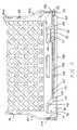
- a bottom 20 of the tray 10can define a lattice pattern.
- the bottom 20can also include longitudinal ribs 176 and transverse ribs 178 .
- the bottom 20can also be domed to increase the strength of the tray 10 and reduce the material required to form the bottom 20 .
- the bottom 20 a of tray 10 acan be domed.
- the shape of a domed bottom surfaceis shown schematically in FIG. 25 .
- the front and sides of the trayare shown in phantom and a line 180 illustrates a profile of the bottom 20 along the transverse direction.
- Line 182illustrates that the bottom can also be arched along the longitudinal direction.
- Line 188illustrates a profile of a bottom that is not domed.
- the dome configuration of a bottomcan increase the strength of the bottom by fifty percent.
- Tray 10 acan include a domed bottom 20 a.
- the enhanced strength of a domed-shaped bottom 20can also reduce the amount of material necessary to form the bottom 20 when a predetermined strength is required.
- the domeis three-eights (3 ⁇ 8) of one inch at the center of the bottom 20 .
- the center of the domeextends toward the interior of the tray 10 three-eights (3 ⁇ 8) of one inch relative to the intersection of the bottom with the sides 16 and 18 , and the front 12 and rear 14 .
- the height of the domecan be increased or decreased as desired.
- the height of the domecan be varied based on the weight of the material and/or products to be maintained in the tray 10 .
- the domecan be completely or partially flattened relative to the intersection of the bottom 20 and with the sides 16 and 18 , and the front 12 and rear 14 in response to a weight of the cargo to be maintained by the tray 10 .
- the height of the domecan be determined based on the projected flattening of the dome in response to weight of the cargo to be maintained by the tray 10 .
- Two or more trayscan be stacked on top of one another in three different configurations.
- the height of two stacked trays in each configurationcan be different.
- the trayscan be blind stacked and unstacked.
- the engagement of two trays 10 and two trays 10 ais substantially similar.
- FIG. 10is a front plan view of two trays stacked in the same orientation and FIG. 13 is a side plan view of two trays stacked in the same orientation.
- a foot 72 a of a rear 14 of an upper trayis received by the notch 44 of the front 12 of a lower tray.
- the traysare moved relative to one another and a runner 134 of the upper tray enters the gain 46 of the front 12 of the lower tray and slides along the channel 158 .
- An edge 184 of the rear foot 122slidingly contacts surface 142 of the second side 18 of the lower tray.
- the runner 134 of the rear foot 122engages the tapered rib 116 and moves past the rib 116 and ribs 114 .
- the runner 132 of the top trayenters the gain 46 of the lower tray.
- the sliding motion of the top tray relative to the bottom traystops when the runner 134 contacts or abuts the stop 160 of the lower tray. As shown in FIG.
- a beam 76 of the top traycontacts the support surface 50 of the boss 42 of the lower tray, the runner 132 of the upper tray engages the surface 152 of the lower tray, the runner 134 of the upper tray engages the surface 156 of the lower tray, and the edge 184 of the upper tray engages the surface 142 of the lower tray and the ribs 114 and 116 . Substantially the same engagement occurs between the first side 16 of the top tray and the first side 16 of the lower tray.
- FIG. 12is a front plan view of two trays stacked in the same orientation and FIG. 14 is a side plan view of two trays stacked in the same orientation.
- a foot 72 of the front 12 of the top trayenters the notch 44 of a lower tray.
- a runner 132enters the gain 46 of the lower tray and slidingly contacts the surfaces 152 and 154 of the channel 158 .
- a runner 134enters the gain 46 .
- the top traydrops into engagement with the bottom tray.
- the ribs 114engage surface 136 to reduce the likelihood that the top tray will move relative to the bottom tray.
- a beam 76 of the top trayis slidingly received in the channel 78 (shown in phantom in FIG.
- runners 128 and 130 of the top traycontact surface 154 of the bottom tray, runner 132 of the top tray pierces the opening 112 of the bottom tray, runner 134 pierces the opening 110 of the bottom tray, and the bottom of the apron 26 of the top tray engages the top of the apron 26 b of the rear 14 of the bottom tray. Substantially the same engagement occurs between the second side 18 of the top tray and the first side 16 of the lower tray.
- FIG. 11is a rear plan view of two trays stacked at an angle of 90° relative to one another.
- the trayscan be stacked so that a bottom edge of a wall 22 of a top tray engages the fillet 24 of the front 12 of a bottom tray and a fillet 24 b of the rear 14 of the bottom tray.
- the shoulder 74 and a shoulder 74 a of the front 12 of the top trayengage the aprons 26 and 26 b and limit the movement of the top tray relative to the bottom tray.
- Like shoulderscan be formed in the rear 14 to engage the aprons 26 and 26 b.
Landscapes
- Engineering & Computer Science (AREA)
- Mechanical Engineering (AREA)
- Food Science & Technology (AREA)
- Stackable Containers (AREA)
Abstract
Description
Claims (19)
Priority Applications (4)
| Application Number | Priority Date | Filing Date | Title |
|---|---|---|---|
| US10/174,698US6886710B2 (en) | 2002-03-26 | 2002-06-19 | Stackable tray having anti-pivot stop and wash apertures |
| CA002419528ACA2419528A1 (en) | 2002-03-26 | 2003-02-19 | Stackable tray having anti-pivot stop and wash apertures |
| MXPA03002475AMXPA03002475A (en) | 2002-03-26 | 2003-03-20 | Stackable tray having anti-pivot stop and wash apertures. |
| US11/508,114USRE44754E1 (en) | 2002-03-26 | 2006-08-22 | Stackable tray having anti-pivot stop and wash apertures |
Applications Claiming Priority (2)
| Application Number | Priority Date | Filing Date | Title |
|---|---|---|---|
| US36768802P | 2002-03-26 | 2002-03-26 | |
| US10/174,698US6886710B2 (en) | 2002-03-26 | 2002-06-19 | Stackable tray having anti-pivot stop and wash apertures |
Related Child Applications (1)
| Application Number | Title | Priority Date | Filing Date |
|---|---|---|---|
| US11/508,114ReissueUSRE44754E1 (en) | 2002-03-26 | 2006-08-22 | Stackable tray having anti-pivot stop and wash apertures |
Publications (2)
| Publication Number | Publication Date |
|---|---|
| US20030183549A1 US20030183549A1 (en) | 2003-10-02 |
| US6886710B2true US6886710B2 (en) | 2005-05-03 |
Family
ID=28456752
Family Applications (2)
| Application Number | Title | Priority Date | Filing Date |
|---|---|---|---|
| US10/174,698CeasedUS6886710B2 (en) | 2002-03-26 | 2002-06-19 | Stackable tray having anti-pivot stop and wash apertures |
| US11/508,114Expired - LifetimeUSRE44754E1 (en) | 2002-03-26 | 2006-08-22 | Stackable tray having anti-pivot stop and wash apertures |
Family Applications After (1)
| Application Number | Title | Priority Date | Filing Date |
|---|---|---|---|
| US11/508,114Expired - LifetimeUSRE44754E1 (en) | 2002-03-26 | 2006-08-22 | Stackable tray having anti-pivot stop and wash apertures |
Country Status (3)
| Country | Link |
|---|---|
| US (2) | US6886710B2 (en) |
| CA (1) | CA2419528A1 (en) |
| MX (1) | MXPA03002475A (en) |
Cited By (34)
| Publication number | Priority date | Publication date | Assignee | Title |
|---|---|---|---|---|
| US20030205495A1 (en)* | 2002-05-03 | 2003-11-06 | Donald Verna | Stackable tray having prestressed sections |
| US20040144680A1 (en)* | 2003-01-24 | 2004-07-29 | Stahl Edward L. | Stackable container |
| US20070102386A1 (en)* | 2004-04-02 | 2007-05-10 | Sanford, L.P. | Nestable and stackable document storage trays |
| US20070175790A1 (en)* | 2006-01-30 | 2007-08-02 | Fernandez Enrique C | Stackable tray |
| US20070187276A1 (en)* | 2005-12-01 | 2007-08-16 | Norseman Plastics Ltd. | Breadbasket with merchandiser window and flaps |
| US20070231281A1 (en)* | 2006-04-04 | 2007-10-04 | Kirker Enterprises, Inc. | Nail enamel compositions having a decorative color effect |
| USD553860S1 (en) | 2006-01-30 | 2007-10-30 | Proarce S.A. De C.V. | Tray |
| USD553859S1 (en) | 2006-01-30 | 2007-10-30 | Proarce S.A. De C.V. | Tray |
| US7320405B2 (en) | 2000-05-09 | 2008-01-22 | Norseman Plastics, Ltd. | Multi-level stacking/nesting tray |
| USD598684S1 (en)* | 2005-12-01 | 2009-08-25 | Norseman Plastics Ltd. | Multi-level sliding stacking container |
| US20100000900A1 (en)* | 2008-07-01 | 2010-01-07 | Hassell Jon P | Bakery tray |
| US7686167B1 (en) | 2006-12-14 | 2010-03-30 | Orbis Canada Limited | Stackable container with front and rear windows, and method for using the same |
| US20100084304A1 (en)* | 2008-10-02 | 2010-04-08 | Cavalcante Mauricio D | Bakery tray |
| US7784615B2 (en) | 2007-05-30 | 2010-08-31 | Orbis Canada Limited | Nestable and stackable container for the transport of heavy baked items |
| US20110037237A1 (en)* | 2009-08-14 | 2011-02-17 | Hassell Jon P | Bakery tray and dolly |
| USD648801S1 (en) | 2011-02-08 | 2011-11-15 | Officemate International Corporation | Document tray |
| USD648802S1 (en) | 2011-02-08 | 2011-11-15 | Officemate International Corporation | Document tray |
| US20120211390A1 (en)* | 2011-02-18 | 2012-08-23 | Hassell Jon P | Bakery tray |
| US20120228174A1 (en)* | 2011-03-11 | 2012-09-13 | Krones Ag | Tray with foldable support |
| US8833594B2 (en) | 2006-07-27 | 2014-09-16 | Orbis Canada Limited | Two position nestable tray with drain channels and scalloped handles |
| US20160096653A1 (en)* | 2014-10-01 | 2016-04-07 | United States Postal Service | Transformable tray and tray system for receiving, transporting and unloading items |
| US20160159542A1 (en)* | 2014-12-04 | 2016-06-09 | Rehrig Pacific Company | Beverage crate |
| US9469470B2 (en) | 2011-03-24 | 2016-10-18 | Orbis Corporation | Three tiered tray |
| US9540140B2 (en) | 2013-10-09 | 2017-01-10 | Rehrig Pacific Company | Bakery tray |
| USD777433S1 (en)* | 2015-01-30 | 2017-01-31 | Polymer Logistics (Israel) Ltd | Crate |
| USD779825S1 (en)* | 2015-01-30 | 2017-02-28 | Polymer Logistics (Israel) Ltd. | Crate |
| USD779826S1 (en)* | 2015-01-30 | 2017-02-28 | Polymer Logistics (Israel) Ltd. | Crate |
| USD779827S1 (en)* | 2015-01-30 | 2017-02-28 | Polymer Logistics (Israel) Ltd. | Crate |
| USD787827S1 (en)* | 2015-01-30 | 2017-05-30 | Polymer Logistics (Israel) Ltd. | Crate |
| US10322850B2 (en) | 2011-03-25 | 2019-06-18 | Rehrig Pacific Company | Bakery tray |
| US10377529B2 (en) | 2008-10-06 | 2019-08-13 | Rehrig Pacific Company | Stackable low depth tray |
| US10421564B2 (en) | 2015-05-12 | 2019-09-24 | United States Postal Service | Systems and methods for loading items into a tray |
| US10611518B2 (en) | 2017-03-01 | 2020-04-07 | Rehrig Pacific Company | Bakery tray |
| US12054313B2 (en) | 2021-12-15 | 2024-08-06 | Orbis Corporation | Tote with side wall drain holes |
Families Citing this family (30)
| Publication number | Priority date | Publication date | Assignee | Title |
|---|---|---|---|---|
| US20050183980A1 (en)* | 2004-01-28 | 2005-08-25 | Fernandez Enrique C. | Stackable tray |
| DE202004014340U1 (en)* | 2004-09-13 | 2006-02-02 | Bekuplast Kunststoffverarbeitungs-Gmbh | Stack nest containers |
| FR2897596B1 (en)* | 2006-02-17 | 2010-08-13 | Caliplast | EMBITABLE-GERBABLE BODY, COMPRISING AT LEAST ONE REINFORCING BAND HAVING A CORRESPONDING WALL WITH A CLEARING SPACE, AND CORRESPONDING MOLD |
| DE102006025198A1 (en)* | 2006-05-29 | 2007-12-06 | "Deutsche See" Gmbh | System box especially for the transport of fresh fish |
| US7861864B2 (en)* | 2006-11-20 | 2011-01-04 | Rehrig Pacific Company | Bakery tray |
| US8348088B2 (en)* | 2007-06-22 | 2013-01-08 | Rehrig Pacific Company | Container with reinforced base |
| US20090020528A1 (en)* | 2007-07-17 | 2009-01-22 | Chang Hung-Sen | Box Assembly that is Assembled Easily and Quickly |
| EP2322437B1 (en)* | 2009-11-17 | 2017-01-11 | Fritz Schäfer GmbH | Plastic storage and transport container |
| EP2595524A4 (en)* | 2010-07-24 | 2014-01-08 | Alexandra Laray Abraham | Basin for use with commercial dish and glassware racks |
| BR112013006610B1 (en)* | 2010-09-20 | 2019-11-19 | Ifco Systems Gmbh | crate |
| US9469429B2 (en) | 2010-09-20 | 2016-10-18 | Ifco Systems Gmbh | Crate |
| PL2431287T3 (en) | 2010-09-20 | 2013-12-31 | Ifco Systems Gmbh | Crate |
| US8960469B1 (en)* | 2010-12-29 | 2015-02-24 | Amazon Technologies, Inc. | Storage system with stacking totes |
| DE202011051215U1 (en)* | 2011-09-06 | 2012-09-10 | Hermesmeyer & Greweling Gmbh & Co.Kg | Standard container in the manner of a box-shaped rotating stacker |
| GB2507066B (en)* | 2012-10-17 | 2015-02-11 | Platipus Anchors Holdings Ltd | Tree anchoring apparatus, kit and method |
| US9260219B2 (en)* | 2012-12-03 | 2016-02-16 | Monoflo International, Inc. | Multi-level bakery tray |
| CA2863692A1 (en)* | 2014-09-17 | 2016-03-17 | 3283688 Nova Scotia Limited | Seafood container |
| FR3033547B1 (en)* | 2015-03-11 | 2017-02-24 | Ip3 Vendee | BAC, IN PARTICULAR A FOOD BIN, OF THE GERBABLE / EMBLED GENUS |
| US10238208B2 (en) | 2016-11-30 | 2019-03-26 | Sabritas S. De R.L. De C.V. | Modular food product display stand |
| USD801088S1 (en)* | 2016-11-30 | 2017-10-31 | Sabritas S. De R.L. De C.V. | Modular food product display stand tray |
| USD802968S1 (en)* | 2016-11-30 | 2017-11-21 | Sabritas S. De R.L. De C.V. | Modular food product display stand tray |
| USD802967S1 (en)* | 2016-11-30 | 2017-11-21 | Sabritas S. De R.L. De C.V. | Modular food product display stand tray |
| US10829268B2 (en)* | 2017-03-21 | 2020-11-10 | Monoflo International, Inc. | Blind-stack and nest-interlock container |
| US20210269194A1 (en)* | 2020-02-28 | 2021-09-02 | Bradshaw Home | Stacking tray system and stackable cookware set |
| CH717584A1 (en)* | 2020-06-29 | 2021-12-30 | Utz Georg Holding Ag | Plastic container with reinforced corner sections. |
| JP7636779B2 (en)* | 2021-03-19 | 2025-02-27 | 岐阜プラスチック工業株式会社 | Transport container with door |
| CN112936717A (en)* | 2021-04-13 | 2021-06-11 | 南京富讯自动化科技有限公司 | Production process of fly maggot breeding plastic tray |
| US12344435B2 (en)* | 2022-04-28 | 2025-07-01 | Intercrate Container Corp. | Sliding stackable container |
| US12263991B2 (en) | 2022-08-24 | 2025-04-01 | Target Brands, Inc. | Interlocking basket system |
| USD1061173S1 (en)* | 2024-05-13 | 2025-02-11 | Junren Huang | Napkin holder |
Citations (35)
| Publication number | Priority date | Publication date | Assignee | Title |
|---|---|---|---|---|
| US3398840A (en) | 1966-10-24 | 1968-08-27 | Banner Metals Inc | Nestable-stackable receptacle |
| US3404804A (en) | 1966-08-15 | 1968-10-08 | Lewis Co G B | Stackable-and nestable container |
| US3405810A (en) | 1966-09-22 | 1968-10-15 | Mid West Metallic Prod Inc | Tierable and nestable receptacle |
| US3613943A (en)* | 1969-12-31 | 1971-10-19 | Phillips Petroleum Co | Nesting and stacking container |
| US3780905A (en) | 1972-01-05 | 1973-12-25 | Vanguard Industries | 90{20 {11 stackable and nestable tray |
| US3865239A (en) | 1973-05-08 | 1975-02-11 | Vanguard Industries | Container assembly |
| US3917108A (en) | 1972-02-22 | 1975-11-04 | Dare Plastics Inc | Plastic tray and method of making same |
| US3934724A (en) | 1974-01-17 | 1976-01-27 | Phillips Petroleum Company | Nest and stack container |
| US4000817A (en) | 1974-05-08 | 1977-01-04 | Pinckney Molded Plastics, Inc. | Three level stacking container |
| US4189052A (en) | 1978-04-03 | 1980-02-19 | Phillips Petroleum Company | Stack and nest container |
| US4211327A (en) | 1978-06-29 | 1980-07-08 | Pinckney Molded Plastics, Inc. | Stack and nest container |
| USD264513S (en) | 1980-02-08 | 1982-05-18 | Nestier Corporation | Bakery tray |
| US4457433A (en) | 1983-01-31 | 1984-07-03 | Wilson James D | Key lock for plastic receptacles |
| US4466541A (en) | 1982-04-26 | 1984-08-21 | Buckhorn Material Handling Group Inc. | Molded container with integral hinge |
| US4520928A (en) | 1983-10-31 | 1985-06-04 | Wilson James D | Nestable/stackable containers for bakery goods and the like |
| US4523681A (en) | 1984-03-05 | 1985-06-18 | Pinckney Molded Plastics, Inc. | Multilevel stacking container |
| US4577759A (en) | 1985-01-18 | 1986-03-25 | Pinckney Molded Plastics, Inc. | Three-level stacking container |
| US4600103A (en) | 1984-03-21 | 1986-07-15 | Buckhorn Material Handling Group, Inc. | Symmetrical bakery basket |
| US4842142A (en) | 1987-12-21 | 1989-06-27 | Pinckney Molded Plastics, Inc. | Open-front, two-level stacking container |
| US4905833A (en) | 1989-02-15 | 1990-03-06 | Pinckney Molded Plastics, Inc. | Nestable and stackable container |
| US4960207A (en) | 1988-11-21 | 1990-10-02 | Buckhorn, Inc. | Bakery tray with blind stacking and unstacking |
| US4982844A (en)* | 1990-06-29 | 1991-01-08 | Mp Acquisition Corp. | Bakery basket |
| US5035326A (en) | 1989-09-05 | 1991-07-30 | Piper Industries Of Texas, Inc. | Multi-level basket |
| US5287966A (en) | 1989-09-05 | 1994-02-22 | Piper Industries Of Texas, Inc. | Slide on multi-level basket |
| US5344022A (en) | 1993-11-19 | 1994-09-06 | Piper Industries Of Texas, Inc. | Stackable and nestable multi-level bread tray |
| US5372257A (en) | 1994-04-20 | 1994-12-13 | Ipl Inc. | Stackable load bearing tray |
| US5582296A (en) | 1994-06-03 | 1996-12-10 | Ipl Inc. | Stackable load bearing tray |
| USD401066S (en) | 1996-09-10 | 1998-11-17 | Rehrig Pacific Company, Inc. | Bread tray |
| US5881902A (en) | 1996-09-10 | 1999-03-16 | Rehrig-Pacific Company, Inc. | Multilevel bakery tray |
| US5913424A (en) | 1993-07-14 | 1999-06-22 | Tulip Corporation | Storage and display trays |
| US5960720A (en) | 1998-05-04 | 1999-10-05 | Borland; Curtis L. | Display Pallet |
| US5984133A (en) | 1997-03-10 | 1999-11-16 | Schutz-Werke Gmbh & Co. Kg | Tighthead barrel |
| US6241096B1 (en) | 1999-06-18 | 2001-06-05 | Fort James Corporation | Disposable servingware with nesting resistant flange patterns |
| US6260706B1 (en) | 1999-10-29 | 2001-07-17 | Rehrig Pacific Company | Multi-purpose tray |
| US6386388B1 (en) | 1999-12-27 | 2002-05-14 | Rehrig Pacific Company | Container |
Family Cites Families (1)
| Publication number | Priority date | Publication date | Assignee | Title |
|---|---|---|---|---|
| US6273259B1 (en) | 2000-05-09 | 2001-08-14 | Norseman Plastics Limited | Container |
- 2002
- 2002-06-19USUS10/174,698patent/US6886710B2/ennot_activeCeased
- 2003
- 2003-02-19CACA002419528Apatent/CA2419528A1/ennot_activeAbandoned
- 2003-03-20MXMXPA03002475Apatent/MXPA03002475A/enactiveIP Right Grant
- 2006
- 2006-08-22USUS11/508,114patent/USRE44754E1/ennot_activeExpired - Lifetime
Patent Citations (35)
| Publication number | Priority date | Publication date | Assignee | Title |
|---|---|---|---|---|
| US3404804A (en) | 1966-08-15 | 1968-10-08 | Lewis Co G B | Stackable-and nestable container |
| US3405810A (en) | 1966-09-22 | 1968-10-15 | Mid West Metallic Prod Inc | Tierable and nestable receptacle |
| US3398840A (en) | 1966-10-24 | 1968-08-27 | Banner Metals Inc | Nestable-stackable receptacle |
| US3613943A (en)* | 1969-12-31 | 1971-10-19 | Phillips Petroleum Co | Nesting and stacking container |
| US3780905A (en) | 1972-01-05 | 1973-12-25 | Vanguard Industries | 90{20 {11 stackable and nestable tray |
| US3917108A (en) | 1972-02-22 | 1975-11-04 | Dare Plastics Inc | Plastic tray and method of making same |
| US3865239A (en) | 1973-05-08 | 1975-02-11 | Vanguard Industries | Container assembly |
| US3934724A (en) | 1974-01-17 | 1976-01-27 | Phillips Petroleum Company | Nest and stack container |
| US4000817A (en) | 1974-05-08 | 1977-01-04 | Pinckney Molded Plastics, Inc. | Three level stacking container |
| US4189052A (en) | 1978-04-03 | 1980-02-19 | Phillips Petroleum Company | Stack and nest container |
| US4211327A (en) | 1978-06-29 | 1980-07-08 | Pinckney Molded Plastics, Inc. | Stack and nest container |
| USD264513S (en) | 1980-02-08 | 1982-05-18 | Nestier Corporation | Bakery tray |
| US4466541A (en) | 1982-04-26 | 1984-08-21 | Buckhorn Material Handling Group Inc. | Molded container with integral hinge |
| US4457433A (en) | 1983-01-31 | 1984-07-03 | Wilson James D | Key lock for plastic receptacles |
| US4520928A (en) | 1983-10-31 | 1985-06-04 | Wilson James D | Nestable/stackable containers for bakery goods and the like |
| US4523681A (en) | 1984-03-05 | 1985-06-18 | Pinckney Molded Plastics, Inc. | Multilevel stacking container |
| US4600103A (en) | 1984-03-21 | 1986-07-15 | Buckhorn Material Handling Group, Inc. | Symmetrical bakery basket |
| US4577759A (en) | 1985-01-18 | 1986-03-25 | Pinckney Molded Plastics, Inc. | Three-level stacking container |
| US4842142A (en) | 1987-12-21 | 1989-06-27 | Pinckney Molded Plastics, Inc. | Open-front, two-level stacking container |
| US4960207A (en) | 1988-11-21 | 1990-10-02 | Buckhorn, Inc. | Bakery tray with blind stacking and unstacking |
| US4905833A (en) | 1989-02-15 | 1990-03-06 | Pinckney Molded Plastics, Inc. | Nestable and stackable container |
| US5035326A (en) | 1989-09-05 | 1991-07-30 | Piper Industries Of Texas, Inc. | Multi-level basket |
| US5287966A (en) | 1989-09-05 | 1994-02-22 | Piper Industries Of Texas, Inc. | Slide on multi-level basket |
| US4982844A (en)* | 1990-06-29 | 1991-01-08 | Mp Acquisition Corp. | Bakery basket |
| US5913424A (en) | 1993-07-14 | 1999-06-22 | Tulip Corporation | Storage and display trays |
| US5344022A (en) | 1993-11-19 | 1994-09-06 | Piper Industries Of Texas, Inc. | Stackable and nestable multi-level bread tray |
| US5372257A (en) | 1994-04-20 | 1994-12-13 | Ipl Inc. | Stackable load bearing tray |
| US5582296A (en) | 1994-06-03 | 1996-12-10 | Ipl Inc. | Stackable load bearing tray |
| US5881902A (en) | 1996-09-10 | 1999-03-16 | Rehrig-Pacific Company, Inc. | Multilevel bakery tray |
| USD401066S (en) | 1996-09-10 | 1998-11-17 | Rehrig Pacific Company, Inc. | Bread tray |
| US5984133A (en) | 1997-03-10 | 1999-11-16 | Schutz-Werke Gmbh & Co. Kg | Tighthead barrel |
| US5960720A (en) | 1998-05-04 | 1999-10-05 | Borland; Curtis L. | Display Pallet |
| US6241096B1 (en) | 1999-06-18 | 2001-06-05 | Fort James Corporation | Disposable servingware with nesting resistant flange patterns |
| US6260706B1 (en) | 1999-10-29 | 2001-07-17 | Rehrig Pacific Company | Multi-purpose tray |
| US6386388B1 (en) | 1999-12-27 | 2002-05-14 | Rehrig Pacific Company | Container |
Cited By (57)
| Publication number | Priority date | Publication date | Assignee | Title |
|---|---|---|---|---|
| US7320405B2 (en) | 2000-05-09 | 2008-01-22 | Norseman Plastics, Ltd. | Multi-level stacking/nesting tray |
| US20030205495A1 (en)* | 2002-05-03 | 2003-11-06 | Donald Verna | Stackable tray having prestressed sections |
| US20040144680A1 (en)* | 2003-01-24 | 2004-07-29 | Stahl Edward L. | Stackable container |
| US7637373B2 (en) | 2003-01-24 | 2009-12-29 | Norseman Plastics, Ltd | Stackable container |
| US20070102386A1 (en)* | 2004-04-02 | 2007-05-10 | Sanford, L.P. | Nestable and stackable document storage trays |
| US20070102385A1 (en)* | 2004-04-02 | 2007-05-10 | Killinger Timothy D | Nestable and stackable document storage trays |
| US20070176358A1 (en)* | 2004-04-02 | 2007-08-02 | Killinger Timothy D | Nestable and stackable document storage trays |
| US8047369B2 (en) | 2005-12-01 | 2011-11-01 | Orbis Canada Limited | Breadbasket with merchandiser window and flaps |
| US20070187276A1 (en)* | 2005-12-01 | 2007-08-16 | Norseman Plastics Ltd. | Breadbasket with merchandiser window and flaps |
| US9296516B2 (en) | 2005-12-01 | 2016-03-29 | Orbis Canada Limited | Breadbasket with merchandiser window and flaps |
| USD598684S1 (en)* | 2005-12-01 | 2009-08-25 | Norseman Plastics Ltd. | Multi-level sliding stacking container |
| US20070175790A1 (en)* | 2006-01-30 | 2007-08-02 | Fernandez Enrique C | Stackable tray |
| USD557011S1 (en) | 2006-01-30 | 2007-12-11 | Proarce S.A. De C.V. | Tray |
| USD553859S1 (en) | 2006-01-30 | 2007-10-30 | Proarce S.A. De C.V. | Tray |
| USD553861S1 (en) | 2006-01-30 | 2007-10-30 | Proarce S.A. De C.V. | Tray |
| USD553860S1 (en) | 2006-01-30 | 2007-10-30 | Proarce S.A. De C.V. | Tray |
| US20070231281A1 (en)* | 2006-04-04 | 2007-10-04 | Kirker Enterprises, Inc. | Nail enamel compositions having a decorative color effect |
| US8765102B2 (en) | 2006-04-04 | 2014-07-01 | Kirker Enterprises, Inc. | Nail enamel compositions having a decorative color effect |
| US20100086505A1 (en)* | 2006-04-04 | 2010-04-08 | Kirker Enterprises, Inc. | Nail enamel compositions having a decorative color effect |
| US7976827B2 (en) | 2006-04-04 | 2011-07-12 | Kirker Enterprises, Inc. | Nail enamel compositions having a decorative color effect |
| US8833594B2 (en) | 2006-07-27 | 2014-09-16 | Orbis Canada Limited | Two position nestable tray with drain channels and scalloped handles |
| US7686167B1 (en) | 2006-12-14 | 2010-03-30 | Orbis Canada Limited | Stackable container with front and rear windows, and method for using the same |
| US7784615B2 (en) | 2007-05-30 | 2010-08-31 | Orbis Canada Limited | Nestable and stackable container for the transport of heavy baked items |
| US8720687B2 (en) | 2008-07-01 | 2014-05-13 | Rehrig Pacific Company | Bakery tray |
| US20100000900A1 (en)* | 2008-07-01 | 2010-01-07 | Hassell Jon P | Bakery tray |
| US9302810B2 (en)* | 2008-10-02 | 2016-04-05 | Rehrig Pacific Company | Bakery tray |
| US20100084304A1 (en)* | 2008-10-02 | 2010-04-08 | Cavalcante Mauricio D | Bakery tray |
| US10377529B2 (en) | 2008-10-06 | 2019-08-13 | Rehrig Pacific Company | Stackable low depth tray |
| US9156588B2 (en) | 2009-08-14 | 2015-10-13 | Rehrig Pacific Company | Bakery tray and dolly |
| US20110037237A1 (en)* | 2009-08-14 | 2011-02-17 | Hassell Jon P | Bakery tray and dolly |
| USD648802S1 (en) | 2011-02-08 | 2011-11-15 | Officemate International Corporation | Document tray |
| USD648801S1 (en) | 2011-02-08 | 2011-11-15 | Officemate International Corporation | Document tray |
| US20120211390A1 (en)* | 2011-02-18 | 2012-08-23 | Hassell Jon P | Bakery tray |
| US9278780B2 (en)* | 2011-02-18 | 2016-03-08 | Rehrig Pacific Company | Bakery tray |
| US20120228174A1 (en)* | 2011-03-11 | 2012-09-13 | Krones Ag | Tray with foldable support |
| US9469470B2 (en) | 2011-03-24 | 2016-10-18 | Orbis Corporation | Three tiered tray |
| US9919838B2 (en) | 2011-03-24 | 2018-03-20 | Orbis Corporation | Three tiered tray |
| US10322850B2 (en) | 2011-03-25 | 2019-06-18 | Rehrig Pacific Company | Bakery tray |
| US9540140B2 (en) | 2013-10-09 | 2017-01-10 | Rehrig Pacific Company | Bakery tray |
| US12162702B2 (en)* | 2014-10-01 | 2024-12-10 | United States Postal Service | Transformable tray and tray system for receiving, transporting and unloading items |
| US20160096653A1 (en)* | 2014-10-01 | 2016-04-07 | United States Postal Service | Transformable tray and tray system for receiving, transporting and unloading items |
| US20220162020A1 (en)* | 2014-10-01 | 2022-05-26 | United States Postal Service | Transformable tray and tray system for receiving, transporting and unloading items |
| US11247854B2 (en) | 2014-10-01 | 2022-02-15 | United States Postal Service | Transformable tray and tray system for receiving, transporting and unloading items |
| US10202248B2 (en)* | 2014-10-01 | 2019-02-12 | United States Postal Service | Transformable tray and tray system for receiving, transporting and unloading items |
| US10822185B2 (en) | 2014-10-01 | 2020-11-03 | United States Postal Service | Transformable tray and tray system for receiving, transporting and unloading items |
| US10913621B2 (en) | 2014-10-01 | 2021-02-09 | United States Postal Service | Transformable tray and tray system for receiving, transporting and unloading items |
| US20160159542A1 (en)* | 2014-12-04 | 2016-06-09 | Rehrig Pacific Company | Beverage crate |
| US11319130B2 (en)* | 2014-12-04 | 2022-05-03 | Rehrig Pacific Company | Beverage crate |
| USD779825S1 (en)* | 2015-01-30 | 2017-02-28 | Polymer Logistics (Israel) Ltd. | Crate |
| USD787827S1 (en)* | 2015-01-30 | 2017-05-30 | Polymer Logistics (Israel) Ltd. | Crate |
| USD779827S1 (en)* | 2015-01-30 | 2017-02-28 | Polymer Logistics (Israel) Ltd. | Crate |
| USD779826S1 (en)* | 2015-01-30 | 2017-02-28 | Polymer Logistics (Israel) Ltd. | Crate |
| USD777433S1 (en)* | 2015-01-30 | 2017-01-31 | Polymer Logistics (Israel) Ltd | Crate |
| US10894686B2 (en) | 2015-05-12 | 2021-01-19 | United States Postal Service | Systems and methods for loading items into a tray |
| US10421564B2 (en) | 2015-05-12 | 2019-09-24 | United States Postal Service | Systems and methods for loading items into a tray |
| US10611518B2 (en) | 2017-03-01 | 2020-04-07 | Rehrig Pacific Company | Bakery tray |
| US12054313B2 (en) | 2021-12-15 | 2024-08-06 | Orbis Corporation | Tote with side wall drain holes |
Also Published As
| Publication number | Publication date |
|---|---|
| CA2419528A1 (en) | 2003-09-26 |
| MXPA03002475A (en) | 2004-08-11 |
| US20030183549A1 (en) | 2003-10-02 |
| USRE44754E1 (en) | 2014-02-11 |
Similar Documents
| Publication | Publication Date | Title |
|---|---|---|
| US6886710B2 (en) | Stackable tray having anti-pivot stop and wash apertures | |
| US11173939B2 (en) | Bakery dolly | |
| JP2677610B2 (en) | Pallet structure | |
| EP0597572B1 (en) | Plastic pallet | |
| US7234599B2 (en) | Portable storage container | |
| US6886475B2 (en) | Plastic pallet | |
| US8448583B2 (en) | Nestable pallet | |
| USRE41323E1 (en) | Transport container | |
| US6394274B1 (en) | Stackable bakery tray | |
| CA1332540C (en) | Bakery tray with blind stacking | |
| US20030205877A1 (en) | Stackable dolly for supporting stackable trays having prestressed sections | |
| US4742781A (en) | Twin sheet pallet with sleeve retaining construction | |
| US6840181B2 (en) | Pallet | |
| US7861864B2 (en) | Bakery tray | |
| US20070056483A1 (en) | Pallet | |
| US6953116B2 (en) | Stackable tray having prestressed sections | |
| GB2060566A (en) | Stackable container | |
| US6659019B2 (en) | Folding pallet-stacking device | |
| JP2001328632A (en) | Plastic pallets | |
| US4165003A (en) | Stackable and nestable containers | |
| JP2000085773A (en) | Carriage container | |
| KR101771015B1 (en) | A pallet for carrying goods | |
| JPH0624343Y2 (en) | Synthetic resin foam pallet | |
| KR101764799B1 (en) | A box assembly for carrying comprising a pallet | |
| JP7630829B2 (en) | Containers and container sets |
Legal Events
| Date | Code | Title | Description |
|---|---|---|---|
| AS | Assignment | Owner name:PINCKNEY MOLDED PLASTICS, INC., MICHIGAN Free format text:ASSIGNMENT OF ASSIGNORS INTEREST;ASSIGNOR:VERNA, DONALD;REEL/FRAME:013027/0484 Effective date:20020524 | |
| AS | Assignment | Owner name:PINCKNEY MOLDED PLASTICS, INC., MICHIGAN Free format text:ASSIGNMENT OF ASSIGNORS INTEREST;ASSIGNOR:COX, DOUGLAS T.;REEL/FRAME:013216/0531 Effective date:20020729 | |
| AS | Assignment | Owner name:PINCKNEY MOLDED PLASTICS, INC., MICHIGAN Free format text:ASSIGNMENT OF ASSIGNORS INTEREST;ASSIGNOR:HOOD, DOUGLAS;REEL/FRAME:013548/0594 Effective date:20021105 | |
| AS | Assignment | Owner name:PINCKNEY MOLDED PLASTICS, INC., MICHIGAN Free format text:ASSIGNMENT OF ASSIGNORS INTEREST;ASSIGNOR:HOOD, DOUGLAS;REEL/FRAME:013582/0052 Effective date:20021105 | |
| AS | Assignment | Owner name:PINCKNEY MOLDED PLASTICS, INC., MICHIGAN Free format text:ASSIGNMENT OF ASSIGNORS INTEREST;ASSIGNOR:VERNA, DONALD;REEL/FRAME:013648/0478 Effective date:20020524 | |
| STCF | Information on status: patent grant | Free format text:PATENTED CASE | |
| RF | Reissue application filed | Effective date:20060822 | |
| AS | Assignment | Owner name:LASALLE BANK MIDWEST NATIONAL ASSOCIATION, MICHIGA Free format text:SECURITY AGREEMENT;ASSIGNOR:PINCKNEY MOLDED PLASTICS, INC.;REEL/FRAME:019440/0624 Effective date:20070523 | |
| FPAY | Fee payment | Year of fee payment:4 | |
| FEPP | Fee payment procedure | Free format text:PAT HOLDER NO LONGER CLAIMS SMALL ENTITY STATUS, ENTITY STATUS SET TO UNDISCOUNTED (ORIGINAL EVENT CODE: STOL); ENTITY STATUS OF PATENT OWNER: LARGE ENTITY | |
| AS | Assignment | Owner name:PINCKNEY MOLDED PLASTICS, INC., MICHIGAN Free format text:RELEASE BY SECURED PARTY;ASSIGNOR:BANK OF AMERICA SUCCESSOR IN INTEREST TO LASALLE BANK MIDWEST NATIONAL ASSOCIATION;REEL/FRAME:027568/0685 Effective date:20120118 | |
| FPAY | Fee payment | Year of fee payment:8 | |
| AS | Assignment | Owner name:MICROBEGUARD, INC, ILLINOIS Free format text:NUNC PRO TUNC ASSIGNMENT;ASSIGNOR:MICROBEGUARD, INC;REEL/FRAME:044401/0033 Effective date:20171201 |