US6886575B2 - Lock release mechanism for foldable walkers - Google Patents
Lock release mechanism for foldable walkersDownload PDFInfo
- Publication number
- US6886575B2 US6886575B2US10/397,972US39797203AUS6886575B2US 6886575 B2US6886575 B2US 6886575B2US 39797203 AUS39797203 AUS 39797203AUS 6886575 B2US6886575 B2US 6886575B2
- Authority
- US
- United States
- Prior art keywords
- locking pin
- actuating lever
- housing
- locking
- bore
- Prior art date
- Legal status (The legal status is an assumption and is not a legal conclusion. Google has not performed a legal analysis and makes no representation as to the accuracy of the status listed.)
- Expired - Lifetime, expires
Links
Images


Classifications
- A—HUMAN NECESSITIES
- A61—MEDICAL OR VETERINARY SCIENCE; HYGIENE
- A61H—PHYSICAL THERAPY APPARATUS, e.g. DEVICES FOR LOCATING OR STIMULATING REFLEX POINTS IN THE BODY; ARTIFICIAL RESPIRATION; MASSAGE; BATHING DEVICES FOR SPECIAL THERAPEUTIC OR HYGIENIC PURPOSES OR SPECIFIC PARTS OF THE BODY
- A61H3/00—Appliances for aiding patients or disabled persons to walk about
- A—HUMAN NECESSITIES
- A45—HAND OR TRAVELLING ARTICLES
- A45B—WALKING STICKS; UMBRELLAS; LADIES' OR LIKE FANS
- A45B7/00—Other sticks, e.g. of cranked shape
- A—HUMAN NECESSITIES
- A45—HAND OR TRAVELLING ARTICLES
- A45B—WALKING STICKS; UMBRELLAS; LADIES' OR LIKE FANS
- A45B9/00—Details
- A45B2009/005—Shafts
- A45B2009/007—Shafts of adjustable length, e.g. telescopic shafts
- A—HUMAN NECESSITIES
- A61—MEDICAL OR VETERINARY SCIENCE; HYGIENE
- A61H—PHYSICAL THERAPY APPARATUS, e.g. DEVICES FOR LOCATING OR STIMULATING REFLEX POINTS IN THE BODY; ARTIFICIAL RESPIRATION; MASSAGE; BATHING DEVICES FOR SPECIAL THERAPEUTIC OR HYGIENIC PURPOSES OR SPECIFIC PARTS OF THE BODY
- A61H2201/00—Characteristics of apparatus not provided for in the preceding codes
- A61H2201/01—Constructive details
- A61H2201/0161—Size reducing arrangements when not in use, for stowing or transport
- Y—GENERAL TAGGING OF NEW TECHNOLOGICAL DEVELOPMENTS; GENERAL TAGGING OF CROSS-SECTIONAL TECHNOLOGIES SPANNING OVER SEVERAL SECTIONS OF THE IPC; TECHNICAL SUBJECTS COVERED BY FORMER USPC CROSS-REFERENCE ART COLLECTIONS [XRACs] AND DIGESTS
- Y10—TECHNICAL SUBJECTS COVERED BY FORMER USPC
- Y10T—TECHNICAL SUBJECTS COVERED BY FORMER US CLASSIFICATION
- Y10T403/00—Joints and connections
- Y10T403/59—Manually releaseable latch type
- Y10T403/591—Manually releaseable latch type having operating mechanism
- Y10T403/595—Lever
Definitions
- This inventionrelates generally to a locking assembly, and more particularly to a locking assembly for use with a foldable walker.
- Prior art locking mechanisms used in connection with foldable walkershave suffered from various drawbacks.
- the drawbacksstem from the limited manual dexterity of handicapped people.
- some prior art assembliesare operated through use of a lever. At least one of these devices requires the user of the walker to push down on the lever to allow for the walker to be folded.
- certain people with limited dexteritymay be incapable of exerting enough downward force to activate such a lever and thus will be unable to operate the locking assembly.
- the lever handles of the prior artare often narrow. This presents additional problems for users having diminished manual dexterity. The narrowness of the handle makes finding and gripping the lever difficult. This is particularly true for users having a debilitating disease affecting their fingers, such as rheumatoid arthritis.
- Still other prior art locking assemblies for walkersutilize a pin actuating plunger located remotely from the handles of the walker.
- these prior art pin actuating plungersare positioned on a cross brace away from a walker's handles.
- a handicapped person with limited dexterityis required to release his/her grip on the handles in order to operate the pin actuating plunger mounted on the cross brace.
- the handicapped useris unbalanced, creating a greater likelihood that the user may fall.
- the handicapped user with limited dexterityis required to use two hands in order to fold each side brace, e.g., using one hand to depress the plunger while the other hand folds in the side brace.
- a locking assemblyfor use with a cylindrical member concentric with and rotatably mounted in a tubular member.
- the locking assemblymay include a locking pin positioned parallel to a longitudinal axis of each of the two members and located external thereto. The locking pin is movable between a first position in which the two members are held in a locked state and a second position in which the members are in an unlocked state so that the two members are able to rotate in relation to each other.
- a lock plateis secured to one of the two members and extends transversely to the longitudinal axis thereof.
- the lock platehas an aperture adapted to receive a locking end of the locking pin when the pin is in the first position.
- a lever assemblyis provided for moving the locking pin from its first position to its second position to permit rotation of the cylindrical member in relation to the tubular member.
- This lever assemblyincludes a housing member attached to another of the two members, and an actuating lever having a force-applying handle end and a housing attach end. A portion of the actuating lever is operatively connected to the locking pin.
- the housing attach end of the actuating leveris pivotally received by the housing member so that when an upward force is applied to the handle end, the actuating lever pivots with respect to the housing member and moves the locking pin to its second position thereby allowing the two members to be movable relative to each other.
- a foldable walkerhaving a pair of side frames each of which has a substantially vertical front tubular leg.
- the foldable walkerfurther includes a cross brace having a pair of substantially vertical end sleeves in which the tubular legs are concentrically contained so that the tubular legs are rotatable between a locked state and an unlocked state.
- a locking assemblyis also provided and is associated with each tubular leg.
- the locking assemblyincludes a first body portion having a first bore through which extends the tubular leg along a first longitudinal axis.
- a fastenerrigidly connects the first body portion to the tubular leg, the fastener extending transversely to the first longitudinal axis and into both the first body portion and the tubular leg.
- a locking pinis movable between a first position in which the tubular leg and sleeve are in a locked state and a second position in which the tubular leg and sleeve are in an unlocked state.
- a second body portion rigidly connected to the first body portionhas a second bore through which extends the locking pin along a second longitudinal axis wherein the first and second longitudinal axes are in relatively parallel position.
- a lock plateis rigidly connected to the end sleeve and extends transversely to the first and second longitudinal axes. The lock plate has an aperture which is adapted to receive a locking end of the locking pin when the locking pin is in its first position.
- an actuating leveris provided which has a force applying handle end and a body attach end operatively connected to at least one of the first and second body portions.
- a portion of the actuator lever between the force applying handle end and the body attach endis coupled to the locking pin such that when an upward force is applied to the force applying handle end, the actuating lever pivots with respect to the body-portions and moves the locking pin from its first position to its second position, thereby allowing the tubular leg to be moved relative to the corresponding end sleeve.
- FIG. 1 ais a perspective view of a foldable walker with one side frame in its folded position and a second side frame in its unfolded position;
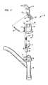
- FIG. 2is an enlarged exploded perspective view of the locking assembly portion for the foldable walker of FIG. 1 .
- FIG. 1shows a walker 10 which includes a pair of spaced side frames 12 and 14 and a cross brace 16 for connecting the two side frames.
- Side frames 12 and 14 , and cross brace 16can be made from a lightweight and sturdy metallic material such as conventional aluminum or steel.
- the metallic material of the side frames and cross braceis tubular in nature to reduce the weight of the walker. Since the right side frame 14 is identical to left side frame 12 , the description of the two is identical. Thus only the left side frame 12 will be described in detail herein.
- the left side frame 12includes a top substantially horizontal support arm joining substantially vertical front and rear legs 20 and 22 .
- a non-sliding hand grip 24fits snugly around the horizontal support arm 18 .
- the hand grip 24is preferably formed from a suitable conventional polymeric material.
- Front and rear tubular leg extensions 26 and 28are Front and rear telescoping tubular leg extensions 26 and 28 , respectively. These telescoping extensions allow the walker to be adjusted in accordance with the height of the individual user.
- the telescoping extensionsare connected to the legs using a snap button and corresponding biasing spring (not shown in the drawings). Because use of snap buttons and biasing springs to provide for walker legs having adjustable lengths is very well known in the art, details of the snap buttons and biasing springs will not be described for reasons of simplicity.
- a crutch tip 50is adapted to fit on the ground-engaging ends of the tubular leg extensions 26 , 28 to prevent sliding movement between the walker 10 and the ground.
- crutch tips 50are preferably made from a suitable conventional thermoplastic material.
- a side brace 54is connected between legs 20 and 22 of each side frame 12 , 14 .
- the side brace 54reinforces the side frame 12 to prevent a spreading of the legs 20 and 22 of the walker 10 when the walker 10 is supporting the weight of the user.
- the cross brace section 16comprises a cross bar connected to a pair of substantially vertical end sleeves 60 and 62 which snugly embrace and surround intermediate portions of the front legs 20 of side frames 12 and 14 , respectively.
- each side frame 12 and 14may be folded inwardly relative to the cross brace 16 as shown in FIG. 1 with respect to side frame 12 . Yet, to make the walker stable during use, the side frames 12 and 14 are required to be locked to the end sleeves 60 and 62 , respectively, to prevent rotation when in the operative, open position as shown in FIG. 1 with respect to side frame 14 .
- a novel locking assembly 70cooperates with each of the front legs 20 and its associated end sleeves 60 , 62 to lock the walker in its operative position, as shown in FIG. 1 for side frame 14 , or to enable the walker to be relatively easily folded into its folded, storage position, as shown in FIG. 1 for side frame 12 .
- the locking assemblywill be described only with respect to right side frame 14 and end sleeve 62 . However, it should be appreciated that an identical locking assembly is provided for left side frame 12 and end sleeve 60 .
- FIG. 2illustrates the locking assembly 70 in an exploded perspective form.
- the locking assembly 70may include a locking pin 72 formed of a suitable metallic material extending through a pin bore 74 of a pin housing 76 .
- a connecting rod 86engages with a portion of locking pin 72 and is utilized to control the position of locking pin 72 within-pin bore 74 .
- connecting rod 86engages with a portion of locking pin 72 somewhat proximal to end 78 thereof. It is understood that connecting rod 86 may engage with another portion of locking pin 72 .
- connecting rod 86is pivotally connected to locking pin 72 .
- a locking end 88 of locking pin 72is adapted to snugly extend through an opening 90 of a lock plate 92 to lock front leg 20 and end sleeve 60 together and retain the walker in the operative, open position.
- the lock plate 92is fixedly attached, such as by welding, to the outer periphery of end sleeve 60 and extends substantially normal thereto.
- a biasing spring 94may surround some or all of the locking pin 72 within the pin bore 74 .
- the springhas a first end 96 which may sit on a pin shoulder seat 98 and a second end 100 which abuts an inner shoulder of the pin bore 74 .
- the biasing spring 94normally urges the pin locking end 88 into the lock plate opening 90 when they are aligned as shown in FIG. 2 .
- the pin housing 76is generally cylindrical having a longitudinal bore 104 extending therethrough and adapted to receive the front leg 20 .
- Pin housing 76may include a recess 106 defined along an upper edge of pin housing 76 and dimensioned to receive a pivot extension.
- Recess 106cooperates with the pivot extension to provide a fulcrum about which an actuating lever 84 may rotate.
- Fasteners in the form of pop rivets (not shown) or the likemay extend through pin housing 76 and the side frame so as to provide a rigid connection therebetween. It should be appreciated that the locking assembly prevents any upward sliding motion of the cross brace 16 .
- the actuating lever 84may include pivot extension 112 that extends from a housing attach end 122 of actuating lever 84 . Pivot extension 112 engages with recess 106 of pin housing 76 so as to provide a fulcrum of actuating lever 84 , as described above. Pivot extension 112 may, for example, have a bulbous shape and be capable of movement within recess 106 so that actuating lever 84 is pivotally attached to pin housing 76 .
- the actuating lever 84may also have a transverse bore 118 which is aligned with the housing bore 104 to accommodate the front leg 20 . The bore 118 is sized or otherwise configured to allow actuating lever rotation about the previously described fulcrum while the tubular front leg 20 is extended therethrough.
- Connecting rod 86may be connected between actuating lever 84 and locking pin 72 .
- An end of connecting rod 86may be pivotally attached to a portion of actuating lever 84 between handle portion 120 and housing attach end 122 of actuating lever 84 .
- locking pin 72To unlock front leg 20 from end sleeve 60 , locking pin 72 must be pulled upwardly so that the locking end 88 thereof is completely removed from the lock plate opening 90 . This action is accomplished by conveniently and efficiently pulling upwardly, using finger-applied pressure, on handle portion 120 of the actuating lever 84 . This, in turn, causes connecting rod 86 to be pulled in a substantially upward direction so as to raise the locking pin 72 within pin bore 74 .
- front leg 20may then be rotated by the patient using hand-applied pressure onto hand grip 24 of the side frame 14 until the side frame 14 is in the folded position. In this way, the right side frame 14 can be folded substantially against the cross brace 16 , since the locking end 88 of locking pin 72 will merely slide over the flat surface of the lock plate 92 and not be fixed thereto.
- the handle portion 120 of actuating lever 84extends beneath hand grip 24 . Because of the proximity between the handle portion 120 and hand grip 24 , a handicapped user need only to extend one or more of his/her fingers so as to engage with the handle portion 120 while the palm and thumb of the same hand continue to engage with the hand grip 24 . During this time, the user of the walker may continue to use the walker as a support device and will be less likely to lose his/her balance when folding the walker.
- the corresponding side framemay be folded inwardly while the user's hand continues to grasp the hand grip 24 of the side frame. In this way, the locking assembly 70 may be actuated and the corresponding side frame may be placed in the folding position without the user having to release his/her grip on hand grip 24 .
Landscapes
- Health & Medical Sciences (AREA)
- Epidemiology (AREA)
- Pain & Pain Management (AREA)
- Physical Education & Sports Medicine (AREA)
- Rehabilitation Therapy (AREA)
- Life Sciences & Earth Sciences (AREA)
- Animal Behavior & Ethology (AREA)
- General Health & Medical Sciences (AREA)
- Public Health (AREA)
- Veterinary Medicine (AREA)
- Rehabilitation Tools (AREA)
Abstract
Description
Claims (27)
Priority Applications (2)
| Application Number | Priority Date | Filing Date | Title |
|---|---|---|---|
| US10/397,972US6886575B2 (en) | 2003-03-25 | 2003-03-25 | Lock release mechanism for foldable walkers |
| US10/843,683US7703465B2 (en) | 2003-03-25 | 2004-05-11 | Lock release mechanism for foldable walkers and rollators |
Applications Claiming Priority (1)
| Application Number | Priority Date | Filing Date | Title |
|---|---|---|---|
| US10/397,972US6886575B2 (en) | 2003-03-25 | 2003-03-25 | Lock release mechanism for foldable walkers |
Related Child Applications (1)
| Application Number | Title | Priority Date | Filing Date |
|---|---|---|---|
| US10/843,683Continuation-In-PartUS7703465B2 (en) | 2003-03-25 | 2004-05-11 | Lock release mechanism for foldable walkers and rollators |
Publications (2)
| Publication Number | Publication Date |
|---|---|
| US20040187901A1 US20040187901A1 (en) | 2004-09-30 |
| US6886575B2true US6886575B2 (en) | 2005-05-03 |
Family
ID=32989120
Family Applications (1)
| Application Number | Title | Priority Date | Filing Date |
|---|---|---|---|
| US10/397,972Expired - LifetimeUS6886575B2 (en) | 2003-03-25 | 2003-03-25 | Lock release mechanism for foldable walkers |
Country Status (1)
| Country | Link |
|---|---|
| US (1) | US6886575B2 (en) |
Cited By (47)
| Publication number | Priority date | Publication date | Assignee | Title |
|---|---|---|---|---|
| US20050236025A1 (en)* | 2004-04-26 | 2005-10-27 | Bradley Gale | Adjustable walker |
| USD525176S1 (en) | 2005-09-30 | 2006-07-18 | Cosco Management, Inc. | Adult walker base component |
| US20060207002A1 (en)* | 2005-03-17 | 2006-09-21 | Bradshaw Scott N | Mobility aid for use with toilet bowl fixture |
| US20070152416A1 (en)* | 2003-10-07 | 2007-07-05 | Willis Phillip M | Mobile support assembly |
| US20070199586A1 (en)* | 2006-02-24 | 2007-08-30 | Juei-Chuan Cheng | Lock assembly of foldable walker |
| US20080041432A1 (en)* | 2005-05-13 | 2008-02-21 | Willis Phillip M | Walking cane assembly |
| US20080093826A1 (en)* | 2003-10-07 | 2008-04-24 | Willis Phillip M | Mobile support assembly |
| US20080111349A1 (en)* | 2006-01-31 | 2008-05-15 | Willis Phillip M | Mobile support assembly |
| US7373942B1 (en)* | 2007-01-08 | 2008-05-20 | Yeager Christine R | Adjustable width walker |
| US20080129016A1 (en)* | 2006-01-31 | 2008-06-05 | Phillip Minyard Willis | Mobile support assembly |
| USD572632S1 (en) | 2003-10-07 | 2008-07-08 | Phillip Minyard Willis | Frame for support device |
| US20080163913A1 (en)* | 2007-01-05 | 2008-07-10 | Fang-Jung Hsiao | Walker for children and adults |
| US20080252043A1 (en)* | 2003-10-07 | 2008-10-16 | Phillip Minyard Willis | Mobile support assembly |
| US20090050187A1 (en)* | 2007-08-20 | 2009-02-26 | Lamb Karen Y | Walker with underarm supports |
| USD603302S1 (en) | 2003-10-07 | 2009-11-03 | Phillip Minyard Willis | Frame for support device |
| US20100175729A1 (en)* | 2004-04-07 | 2010-07-15 | Shane Obitts | Foldable durable product, such as a patient aid device or walker, and method of forming same |
| US20100180713A1 (en)* | 2009-01-21 | 2010-07-22 | Wei-Chen Tseng | Expanding and retracting structure for a control shaft of a bicycle |
| US7931036B1 (en)* | 2008-04-17 | 2011-04-26 | Chad Eric Hobbs | In-use adjustable walker |
| US20110140394A1 (en)* | 2008-07-08 | 2011-06-16 | Phillip Minyard Willis | Mobile support assembly |
| US20130140781A1 (en)* | 2011-12-02 | 2013-06-06 | Prinos Solutions, Llc | Walking safety aid apparatus |
| US8479755B2 (en)* | 2011-11-18 | 2013-07-09 | Gentry Way Co., Ltd. | Ambulatory aid |
| US20140109943A1 (en)* | 2012-10-23 | 2014-04-24 | Hui Zhou Andon Industries Co., Ltd. | Walker |
| US20150130166A1 (en)* | 2012-03-13 | 2015-05-14 | Invacare International Sarl | Height adjustment device for a handle of a rollator |
| US9173802B2 (en) | 2003-10-07 | 2015-11-03 | Amg Medical, Usa. | Mobile support assembly |
| US20150328079A1 (en)* | 2014-05-15 | 2015-11-19 | Howard J. Liles | Sit-to-Stand and Walking Assistive Mobility Aid |
| US9192541B2 (en) | 2008-10-08 | 2015-11-24 | Evolution Technologies Inc. | Foldable walker apparatus |
| US9320672B2 (en) | 2010-10-29 | 2016-04-26 | Evolution Technolgies Inc. | Foldable walker apparatus |
| US9339432B2 (en) | 2014-02-28 | 2016-05-17 | Evolution Technologies Inc. | Walker apparatus and backrest therefor |
| US9415635B2 (en) | 2010-10-29 | 2016-08-16 | Evolution Technologies Inc. | Foldable walker apparatus |
| US20160262970A1 (en)* | 2009-11-18 | 2016-09-15 | Katherine Lutz | Method for gait training using walker device |
| US20160374890A1 (en)* | 2015-06-29 | 2016-12-29 | Care & Care Health Products Co., Ltd. | Foldable walker |
| US9585807B2 (en) | 2015-05-16 | 2017-03-07 | Protostar, Inc., a Delaware Corporation | Collapsible upright wheeled walker apparatus |
| US9623888B2 (en) | 2008-10-08 | 2017-04-18 | Evolution Technologies Inc. | Foldable walker apparatus |
| USD793915S1 (en)* | 2014-01-20 | 2017-08-08 | Medline Industries, Inc. | Walker with a seat |
| US9744094B2 (en) | 2014-02-28 | 2017-08-29 | Evolution Technologies Inc. | Walker apparatus and backrest therefor |
| US10053062B2 (en) | 2015-09-02 | 2018-08-21 | Evolution Technologies Inc. | Brake assembly for a height-adjustable walker apparatus |
| USD828701S1 (en) | 2017-02-17 | 2018-09-18 | Evolution Technologies Inc. | Set of seat cushions |
| US10307321B2 (en) | 2017-10-06 | 2019-06-04 | Protostar, Inc., a Delaware Corporation | Wheeled walker with a movable seat |
| US10426690B2 (en) | 2018-02-09 | 2019-10-01 | Care & Care Health Products Co., Ltd. | Foldable walker |
| US10555866B2 (en) | 2017-10-06 | 2020-02-11 | Protostar, Inc., a Delaware Corporation | Wheeled walker wheel direction lock apparatus and method |
| US10617592B2 (en) | 2017-10-06 | 2020-04-14 | Protostar, Inc., a Delaware Corporation | Wheeled walker |
| USD886494S1 (en) | 2016-02-26 | 2020-06-09 | Evolution Technologies Inc. | Set of seat cushions |
| US10730489B2 (en) | 2015-09-02 | 2020-08-04 | Evolution Technologies Inc. | Brake assembly for height-adjustable patient transport apparatus |
| US11071676B2 (en) | 2019-04-05 | 2021-07-27 | Protostar, Inc. | Collapsible wheeled walker with stability enhancing bracket apparatus and method |
| US20220079399A1 (en)* | 2020-09-17 | 2022-03-17 | Christine Anne Buckingham | Toilet Frame |
| USD966949S1 (en)* | 2020-08-17 | 2022-10-18 | Cvs Pharmacy, Inc. | Walking frame |
| US11648922B2 (en) | 2015-09-02 | 2023-05-16 | Evolution Technologies Inc. | Manually-operated, height-adjustable wheeled vehicle, and a brake assembly and wheel fork assembly thereof |
Families Citing this family (3)
| Publication number | Priority date | Publication date | Assignee | Title |
|---|---|---|---|---|
| US20060117614A1 (en)* | 2004-12-07 | 2006-06-08 | Lee Margaret H | Quilting pressing table and method of use |
| CN201052246Y (en)* | 2007-06-13 | 2008-04-30 | 佛山市南海建泰铝制品有限公司 | Walking assisting device |
| US20180133081A1 (en) | 2016-11-16 | 2018-05-17 | Henry R. Kaufman | Portable Frame |
Citations (22)
| Publication number | Priority date | Publication date | Assignee | Title |
|---|---|---|---|---|
| US2796916A (en)* | 1954-06-10 | 1957-06-25 | Womble James Floy | Folding walking aid |
| GB919044A (en) | 1960-06-21 | 1963-02-20 | Alexander Thomas | Improvements in walking aids |
| US3658079A (en) | 1970-09-18 | 1972-04-25 | Carstens Health Ind Inc | Folding walker |
| US3688789A (en)* | 1971-02-22 | 1972-09-05 | Charles B Bunch | Foldable article and latch mechanism therefor |
| US3690652A (en) | 1971-06-07 | 1972-09-12 | Parker Machine Co Inc | Foldable invalid walker convertible from fixed to swingable walker |
| US3783886A (en)* | 1971-09-24 | 1974-01-08 | M Thomas | Folding walker |
| US4298016A (en) | 1980-06-23 | 1981-11-03 | Garelick Mfg. Co. | Locking mechanism for foldable walker |
| US4461471A (en) | 1982-05-03 | 1984-07-24 | White Cap Enterprises Corporation | Walker |
| US4518002A (en) | 1982-11-08 | 1985-05-21 | Tubular Fabricators Ind., Inc. | Foldable walker with plunger actuated latch assembly |
| US4640301A (en) | 1982-11-08 | 1987-02-03 | Tubular Fabricators Industry, Inc. | Foldable walker with plunger actuated latch assembly |
| US4830035A (en) | 1987-05-13 | 1989-05-16 | Liu Antony Ching Fong | Seesawly-controlled foldable walker |
| US5188139A (en) | 1991-11-08 | 1993-02-23 | Garelick Mfg. Co. | Foldable support device |
| US5201333A (en)* | 1991-09-10 | 1993-04-13 | Lumex, Inc. | Folding walker |
| US5255696A (en) | 1991-05-17 | 1993-10-26 | Diamond Medical Equipment Corp. | Walker release button |
| US5275187A (en)* | 1991-10-17 | 1994-01-04 | The Kendall Company | Foldable walker |
| US5433235A (en) | 1993-11-12 | 1995-07-18 | Guardian Products, Inc. | Foldable and lockable walker |
| US5529425A (en)* | 1994-07-19 | 1996-06-25 | Invacare Corporation | Foldable walker with a locking mechanism |
| US5692762A (en) | 1995-06-26 | 1997-12-02 | Invacare Corporation | Walker with glide assembly |
| US5862825A (en)* | 1997-08-06 | 1999-01-26 | Graham-Field, Inc. | Walker |
| US6279591B1 (en) | 1997-04-15 | 2001-08-28 | Invacare Corporation | Universal platform support for a walker |
| USD480666S1 (en) | 2001-10-12 | 2003-10-14 | Invacare Corporation | Rollator |
| US6729342B2 (en)* | 2002-06-05 | 2004-05-04 | Dr. K Healthcare Products, Inc. | Walker with release mechanism |
- 2003
- 2003-03-25USUS10/397,972patent/US6886575B2/ennot_activeExpired - Lifetime
Patent Citations (22)
| Publication number | Priority date | Publication date | Assignee | Title |
|---|---|---|---|---|
| US2796916A (en)* | 1954-06-10 | 1957-06-25 | Womble James Floy | Folding walking aid |
| GB919044A (en) | 1960-06-21 | 1963-02-20 | Alexander Thomas | Improvements in walking aids |
| US3658079A (en) | 1970-09-18 | 1972-04-25 | Carstens Health Ind Inc | Folding walker |
| US3688789A (en)* | 1971-02-22 | 1972-09-05 | Charles B Bunch | Foldable article and latch mechanism therefor |
| US3690652A (en) | 1971-06-07 | 1972-09-12 | Parker Machine Co Inc | Foldable invalid walker convertible from fixed to swingable walker |
| US3783886A (en)* | 1971-09-24 | 1974-01-08 | M Thomas | Folding walker |
| US4298016A (en) | 1980-06-23 | 1981-11-03 | Garelick Mfg. Co. | Locking mechanism for foldable walker |
| US4461471A (en) | 1982-05-03 | 1984-07-24 | White Cap Enterprises Corporation | Walker |
| US4518002A (en) | 1982-11-08 | 1985-05-21 | Tubular Fabricators Ind., Inc. | Foldable walker with plunger actuated latch assembly |
| US4640301A (en) | 1982-11-08 | 1987-02-03 | Tubular Fabricators Industry, Inc. | Foldable walker with plunger actuated latch assembly |
| US4830035A (en) | 1987-05-13 | 1989-05-16 | Liu Antony Ching Fong | Seesawly-controlled foldable walker |
| US5255696A (en) | 1991-05-17 | 1993-10-26 | Diamond Medical Equipment Corp. | Walker release button |
| US5201333A (en)* | 1991-09-10 | 1993-04-13 | Lumex, Inc. | Folding walker |
| US5275187A (en)* | 1991-10-17 | 1994-01-04 | The Kendall Company | Foldable walker |
| US5188139A (en) | 1991-11-08 | 1993-02-23 | Garelick Mfg. Co. | Foldable support device |
| US5433235A (en) | 1993-11-12 | 1995-07-18 | Guardian Products, Inc. | Foldable and lockable walker |
| US5529425A (en)* | 1994-07-19 | 1996-06-25 | Invacare Corporation | Foldable walker with a locking mechanism |
| US5692762A (en) | 1995-06-26 | 1997-12-02 | Invacare Corporation | Walker with glide assembly |
| US6279591B1 (en) | 1997-04-15 | 2001-08-28 | Invacare Corporation | Universal platform support for a walker |
| US5862825A (en)* | 1997-08-06 | 1999-01-26 | Graham-Field, Inc. | Walker |
| USD480666S1 (en) | 2001-10-12 | 2003-10-14 | Invacare Corporation | Rollator |
| US6729342B2 (en)* | 2002-06-05 | 2004-05-04 | Dr. K Healthcare Products, Inc. | Walker with release mechanism |
Cited By (73)
| Publication number | Priority date | Publication date | Assignee | Title |
|---|---|---|---|---|
| USD572632S1 (en) | 2003-10-07 | 2008-07-08 | Phillip Minyard Willis | Frame for support device |
| US7837208B2 (en) | 2003-10-07 | 2010-11-23 | Phillip Minyard Willis | Mobile support assembly |
| US8313116B2 (en) | 2003-10-07 | 2012-11-20 | Amg Medical, Usa. | Mobile support assembly |
| US20070152416A1 (en)* | 2003-10-07 | 2007-07-05 | Willis Phillip M | Mobile support assembly |
| US7926834B2 (en) | 2003-10-07 | 2011-04-19 | AMG Medical, USA | Mobile support assembly |
| USD603302S1 (en) | 2003-10-07 | 2009-11-03 | Phillip Minyard Willis | Frame for support device |
| US20080093826A1 (en)* | 2003-10-07 | 2008-04-24 | Willis Phillip M | Mobile support assembly |
| US7540527B2 (en) | 2003-10-07 | 2009-06-02 | Phillip Minyard Willis | Mobile support assembly |
| US9173802B2 (en) | 2003-10-07 | 2015-11-03 | Amg Medical, Usa. | Mobile support assembly |
| US20080252043A1 (en)* | 2003-10-07 | 2008-10-16 | Phillip Minyard Willis | Mobile support assembly |
| US20100175729A1 (en)* | 2004-04-07 | 2010-07-15 | Shane Obitts | Foldable durable product, such as a patient aid device or walker, and method of forming same |
| US7278436B2 (en) | 2004-04-26 | 2007-10-09 | Cosco Management, Inc. | Adjustable walker |
| US20050236025A1 (en)* | 2004-04-26 | 2005-10-27 | Bradley Gale | Adjustable walker |
| US20060207002A1 (en)* | 2005-03-17 | 2006-09-21 | Bradshaw Scott N | Mobility aid for use with toilet bowl fixture |
| US20080041432A1 (en)* | 2005-05-13 | 2008-02-21 | Willis Phillip M | Walking cane assembly |
| USD525176S1 (en) | 2005-09-30 | 2006-07-18 | Cosco Management, Inc. | Adult walker base component |
| US20080129016A1 (en)* | 2006-01-31 | 2008-06-05 | Phillip Minyard Willis | Mobile support assembly |
| US7451992B2 (en) | 2006-01-31 | 2008-11-18 | Phillip Minyard Willis | Mobile support assembly |
| US20080111349A1 (en)* | 2006-01-31 | 2008-05-15 | Willis Phillip M | Mobile support assembly |
| US20070199586A1 (en)* | 2006-02-24 | 2007-08-30 | Juei-Chuan Cheng | Lock assembly of foldable walker |
| US20080163913A1 (en)* | 2007-01-05 | 2008-07-10 | Fang-Jung Hsiao | Walker for children and adults |
| US7506657B2 (en)* | 2007-01-05 | 2009-03-24 | Fang-Jung Hsiao | Walker for children and adults |
| US7373942B1 (en)* | 2007-01-08 | 2008-05-20 | Yeager Christine R | Adjustable width walker |
| US20090050187A1 (en)* | 2007-08-20 | 2009-02-26 | Lamb Karen Y | Walker with underarm supports |
| US7931036B1 (en)* | 2008-04-17 | 2011-04-26 | Chad Eric Hobbs | In-use adjustable walker |
| US20110140394A1 (en)* | 2008-07-08 | 2011-06-16 | Phillip Minyard Willis | Mobile support assembly |
| US8439376B2 (en) | 2008-07-08 | 2013-05-14 | Amg Medical, Usa. | Mobile support assembly |
| US9623888B2 (en) | 2008-10-08 | 2017-04-18 | Evolution Technologies Inc. | Foldable walker apparatus |
| US9192541B2 (en) | 2008-10-08 | 2015-11-24 | Evolution Technologies Inc. | Foldable walker apparatus |
| US20100180713A1 (en)* | 2009-01-21 | 2010-07-22 | Wei-Chen Tseng | Expanding and retracting structure for a control shaft of a bicycle |
| US20160262970A1 (en)* | 2009-11-18 | 2016-09-15 | Katherine Lutz | Method for gait training using walker device |
| US11000440B2 (en) | 2009-11-18 | 2021-05-11 | Katherine Haik | Walker device for gait training |
| US9956131B2 (en)* | 2009-11-18 | 2018-05-01 | Katherine Haik | Method for gait training using walker device |
| US11986435B2 (en) | 2009-11-18 | 2024-05-21 | Katherine Haik | Walker device for gait training |
| US9320672B2 (en) | 2010-10-29 | 2016-04-26 | Evolution Technolgies Inc. | Foldable walker apparatus |
| US9415635B2 (en) | 2010-10-29 | 2016-08-16 | Evolution Technologies Inc. | Foldable walker apparatus |
| US8479755B2 (en)* | 2011-11-18 | 2013-07-09 | Gentry Way Co., Ltd. | Ambulatory aid |
| US9180064B2 (en)* | 2011-12-02 | 2015-11-10 | Michael R. Prather | Walking safety aid apparatus |
| US20130140781A1 (en)* | 2011-12-02 | 2013-06-06 | Prinos Solutions, Llc | Walking safety aid apparatus |
| US9226869B2 (en)* | 2012-03-13 | 2016-01-05 | Invacare International Sarl | Height adjustment device for a handle of a rollator |
| US20150130166A1 (en)* | 2012-03-13 | 2015-05-14 | Invacare International Sarl | Height adjustment device for a handle of a rollator |
| US20140109943A1 (en)* | 2012-10-23 | 2014-04-24 | Hui Zhou Andon Industries Co., Ltd. | Walker |
| USD793915S1 (en)* | 2014-01-20 | 2017-08-08 | Medline Industries, Inc. | Walker with a seat |
| US9339432B2 (en) | 2014-02-28 | 2016-05-17 | Evolution Technologies Inc. | Walker apparatus and backrest therefor |
| US9744094B2 (en) | 2014-02-28 | 2017-08-29 | Evolution Technologies Inc. | Walker apparatus and backrest therefor |
| US20150328079A1 (en)* | 2014-05-15 | 2015-11-19 | Howard J. Liles | Sit-to-Stand and Walking Assistive Mobility Aid |
| US9597251B2 (en)* | 2014-05-15 | 2017-03-21 | Edison Nation Medical, Llc | Sit-to-stand and walking assistive mobility aid |
| US10085909B2 (en) | 2015-05-16 | 2018-10-02 | Protostar, Inc., a Delaware Corporation | Collapsible upright wheeled walker apparatus |
| US9585807B2 (en) | 2015-05-16 | 2017-03-07 | Protostar, Inc., a Delaware Corporation | Collapsible upright wheeled walker apparatus |
| US10322056B2 (en) | 2015-05-16 | 2019-06-18 | Protostar, Inc., a Delaware Corporation | Collapsible upright wheeled walker apparatus |
| US10588815B2 (en) | 2015-05-16 | 2020-03-17 | Protostar, Inc. | Collapsible upright wheeled walker apparatus |
| US10828226B2 (en) | 2015-05-16 | 2020-11-10 | Protostar, Inc., a Delaware Corporation | Collapsible upright wheeled walker apparatus |
| US9700479B2 (en)* | 2015-06-29 | 2017-07-11 | Care & Care Health Products Co., Ltd. | Foldable walker |
| US20160374890A1 (en)* | 2015-06-29 | 2016-12-29 | Care & Care Health Products Co., Ltd. | Foldable walker |
| US10053062B2 (en) | 2015-09-02 | 2018-08-21 | Evolution Technologies Inc. | Brake assembly for a height-adjustable walker apparatus |
| US11648922B2 (en) | 2015-09-02 | 2023-05-16 | Evolution Technologies Inc. | Manually-operated, height-adjustable wheeled vehicle, and a brake assembly and wheel fork assembly thereof |
| US11220246B2 (en) | 2015-09-02 | 2022-01-11 | Evolution Technologies Inc. | Brake assembly for height-adjustable patient transport apparatus |
| US10730489B2 (en) | 2015-09-02 | 2020-08-04 | Evolution Technologies Inc. | Brake assembly for height-adjustable patient transport apparatus |
| USD886494S1 (en) | 2016-02-26 | 2020-06-09 | Evolution Technologies Inc. | Set of seat cushions |
| USD828701S1 (en) | 2017-02-17 | 2018-09-18 | Evolution Technologies Inc. | Set of seat cushions |
| US10617592B2 (en) | 2017-10-06 | 2020-04-14 | Protostar, Inc., a Delaware Corporation | Wheeled walker |
| US10973730B2 (en) | 2017-10-06 | 2021-04-13 | Protostar, Inc., a Delaware Corporation | Wheeled walker |
| US10555866B2 (en) | 2017-10-06 | 2020-02-11 | Protostar, Inc., a Delaware Corporation | Wheeled walker wheel direction lock apparatus and method |
| US10307321B2 (en) | 2017-10-06 | 2019-06-04 | Protostar, Inc., a Delaware Corporation | Wheeled walker with a movable seat |
| US10426690B2 (en) | 2018-02-09 | 2019-10-01 | Care & Care Health Products Co., Ltd. | Foldable walker |
| US11071676B2 (en) | 2019-04-05 | 2021-07-27 | Protostar, Inc. | Collapsible wheeled walker with stability enhancing bracket apparatus and method |
| USD966949S1 (en)* | 2020-08-17 | 2022-10-18 | Cvs Pharmacy, Inc. | Walking frame |
| USD977374S1 (en) | 2020-08-17 | 2023-02-07 | Cvs Pharmacy, Inc. | Walking frame |
| USD977375S1 (en) | 2020-08-17 | 2023-02-07 | Cvs Pharmacy, Inc. | Walking frame |
| US11877977B2 (en) | 2020-08-17 | 2024-01-23 | Cvs Pharmacy, Inc. | Foldable walking frame with ergonomic adjustment features |
| US12226362B2 (en) | 2020-08-17 | 2025-02-18 | Cvs Pharmacy, Inc. | Foldable walking frame with ergonomic adjustment features |
| US20220079399A1 (en)* | 2020-09-17 | 2022-03-17 | Christine Anne Buckingham | Toilet Frame |
| US11786087B2 (en)* | 2020-09-17 | 2023-10-17 | Christine Anne Buckingham | Toilet frame |
Also Published As
| Publication number | Publication date |
|---|---|
| US20040187901A1 (en) | 2004-09-30 |
Similar Documents
| Publication | Publication Date | Title |
|---|---|---|
| US6886575B2 (en) | Lock release mechanism for foldable walkers | |
| US7703465B2 (en) | Lock release mechanism for foldable walkers and rollators | |
| US5529425A (en) | Foldable walker with a locking mechanism | |
| US6729342B2 (en) | Walker with release mechanism | |
| US8511694B2 (en) | Reversible walker assembly | |
| US5201333A (en) | Folding walker | |
| US8708363B1 (en) | Folding walker | |
| US5605169A (en) | Collapsible walker with a retractable seat | |
| US4907794A (en) | Foldable rolling walker | |
| US10772399B2 (en) | Hinged walking cane | |
| US7306246B2 (en) | Highly collapsible ambulatory assistive walker apparatus | |
| EP1228938B1 (en) | Folding stroller | |
| US20180021206A1 (en) | Rollator | |
| JP2021536345A (en) | Foldable walking device | |
| US20130319488A1 (en) | Folding walker with height adjustable crutches | |
| US5862825A (en) | Walker | |
| KR101433339B1 (en) | Stick | |
| US20150328079A1 (en) | Sit-to-Stand and Walking Assistive Mobility Aid | |
| CN109381328B (en) | Link mechanism and walking aid | |
| US7131166B2 (en) | Multiple self locking hinge assembly | |
| US20120167933A1 (en) | Length Adjustable Crutch | |
| US20220151860A1 (en) | Wheeled walker with arm resistance mechanism and method | |
| EP2777677A1 (en) | A mobile support assembly | |
| US10617591B1 (en) | Folding scooter | |
| JP2503312B2 (en) | Walking aid |
Legal Events
| Date | Code | Title | Description |
|---|---|---|---|
| AS | Assignment | Owner name:MEDICAL DEPOT, NEW YORK Free format text:ASSIGNMENT OF ASSIGNORS INTEREST;ASSIGNOR:DIAMOND, HARVEY;REEL/FRAME:014275/0937 Effective date:20030704 | |
| AS | Assignment | Owner name:MEDICAL DEPOT, INC., NEW YORK Free format text:ASSIGNMENT OF ASSIGNORS INTEREST;ASSIGNOR:DIAMOND, HARVEY;REEL/FRAME:014667/0010 Effective date:20031030 | |
| AS | Assignment | Owner name:WEBSTER BUSINESS CREDIT CORPORATION, NEW YORK Free format text:SECURITY AGREEMENT;ASSIGNOR:MEDICAL DEPOT, INC.;REEL/FRAME:015017/0865 Effective date:20040629 | |
| STCF | Information on status: patent grant | Free format text:PATENTED CASE | |
| FEPP | Fee payment procedure | Free format text:PAT HOLDER CLAIMS SMALL ENTITY STATUS, ENTITY STATUS SET TO SMALL (ORIGINAL EVENT CODE: LTOS); ENTITY STATUS OF PATENT OWNER: LARGE ENTITY | |
| FPAY | Fee payment | Year of fee payment:4 | |
| AS | Assignment | Owner name:WEBSTER BUSINESS CREDIT CORPORATION, AS AGENT, NEW Free format text:SECURITY AGREEMENT;ASSIGNOR:MEDICAL DEPOT, INC.;REEL/FRAME:026108/0674 Effective date:20110316 | |
| FEPP | Fee payment procedure | Free format text:PAT HOLDER NO LONGER CLAIMS SMALL ENTITY STATUS, ENTITY STATUS SET TO UNDISCOUNTED (ORIGINAL EVENT CODE: STOL); ENTITY STATUS OF PATENT OWNER: LARGE ENTITY | |
| REFU | Refund | Free format text:REFUND - PAYMENT OF MAINTENANCE FEE, 8TH YR, SMALL ENTITY (ORIGINAL EVENT CODE: R2552); ENTITY STATUS OF PATENT OWNER: LARGE ENTITY | |
| FPAY | Fee payment | Year of fee payment:8 | |
| AS | Assignment | Owner name:GENERAL ELECTRIC CAPITAL CORPORATION, AS AGENT, MA Free format text:SECURITY AGREEMENT;ASSIGNOR:MEDICAL DEPOT, INC.;REEL/FRAME:031307/0117 Effective date:20130927 | |
| AS | Assignment | Owner name:MEDICAL DEPOT, INC., NEW YORK Free format text:RELEASE BY SECURED PARTY;ASSIGNOR:WEBSTER BUSINESS CREDIT CORPORATION;REEL/FRAME:031310/0274 Effective date:20130927 | |
| AS | Assignment | Owner name:HEALTHCARE FINANCIAL SOLUTIONS, LLC, AS SUCCESSOR Free format text:ASSIGNMENT OF INTELLECTUAL PROPERTY SECURITY AGREEMENT;ASSIGNOR:GENERAL ELECTRIC CAPITAL CORPORATION, AS RETIRING AGENT;REEL/FRAME:037145/0518 Effective date:20151116 | |
| FPAY | Fee payment | Year of fee payment:12 | |
| AS | Assignment | Owner name:MEDICAL DEPOT, INC., NEW YORK Free format text:RELEASE BY SECURED PARTY;ASSIGNOR:HEALTHCARE FINANCIAL SOLUTIONS, LLC;REEL/FRAME:040832/0544 Effective date:20170103 | |
| AS | Assignment | Owner name:JPMORGAN CHASE BANK, N.A., AS COLLATERAL AGENT, IL Free format text:NOTICE AND CONFIRMATION OF GRANT OF SECURITY INTEREST IN PATENTS - FIRST LIEN;ASSIGNOR:MEDICAL DEPOT, INC.;REEL/FRAME:041455/0589 Effective date:20170103 Owner name:BARCLAYS BANK PLC, AS COLLATERAL AGENT, NEW YORK Free format text:NOTICE AND CONFIRMATION OF GRANT OF SECURITY INTEREST IN PATENTS - SECOND LIEN;ASSIGNOR:MEDICAL DEPOT, INC.;REEL/FRAME:041458/0927 Effective date:20170103 | |
| AS | Assignment | Owner name:DELAWARE TRUST COMPANY, AS COLLATERAL AGENT, DELAW Free format text:SECURITY INTEREST;ASSIGNOR:MEDICAL DEPOT, INC.;REEL/FRAME:050628/0436 Effective date:20191003 Owner name:DELAWARE TRUST COMPANY, AS COLLATERAL AGENT, DELAWARE Free format text:SECURITY INTEREST;ASSIGNOR:MEDICAL DEPOT, INC.;REEL/FRAME:050628/0436 Effective date:20191003 | |
| AS | Assignment | Owner name:MEDICAL DEPOT, INC., NEW YORK Free format text:TERMINATION AND RELEASE OF SECURITY INTEREST IN PATENTS;ASSIGNOR:DELAWARE TRUST COMPANY;REEL/FRAME:056990/0271 Effective date:20210331 |