US6886469B2 - Distributed charge inflator system - Google Patents
Distributed charge inflator systemDownload PDFInfo
- Publication number
- US6886469B2 US6886469B2US10/146,933US14693302AUS6886469B2US 6886469 B2US6886469 B2US 6886469B2US 14693302 AUS14693302 AUS 14693302AUS 6886469 B2US6886469 B2US 6886469B2
- Authority
- US
- United States
- Prior art keywords
- charge
- inflatable
- inflatable component
- housing body
- distributed
- Prior art date
- Legal status (The legal status is an assumption and is not a legal conclusion. Google has not performed a legal analysis and makes no representation as to the accuracy of the status listed.)
- Expired - Fee Related, expires
Links
Images


Classifications
- B—PERFORMING OPERATIONS; TRANSPORTING
- B60—VEHICLES IN GENERAL
- B60R—VEHICLES, VEHICLE FITTINGS, OR VEHICLE PARTS, NOT OTHERWISE PROVIDED FOR
- B60R21/00—Arrangements or fittings on vehicles for protecting or preventing injuries to occupants or pedestrians in case of accidents or other traffic risks
- B60R21/02—Occupant safety arrangements or fittings, e.g. crash pads
- B60R21/16—Inflatable occupant restraints or confinements designed to inflate upon impact or impending impact, e.g. air bags
- B60R21/23—Inflatable members
- B60R21/231—Inflatable members characterised by their shape, construction or spatial configuration
- B60R21/23138—Inflatable members characterised by their shape, construction or spatial configuration specially adapted for side protection
- B—PERFORMING OPERATIONS; TRANSPORTING
- B60—VEHICLES IN GENERAL
- B60R—VEHICLES, VEHICLE FITTINGS, OR VEHICLE PARTS, NOT OTHERWISE PROVIDED FOR
- B60R21/00—Arrangements or fittings on vehicles for protecting or preventing injuries to occupants or pedestrians in case of accidents or other traffic risks
- B60R21/02—Occupant safety arrangements or fittings, e.g. crash pads
- B60R21/16—Inflatable occupant restraints or confinements designed to inflate upon impact or impending impact, e.g. air bags
- B60R21/26—Inflatable occupant restraints or confinements designed to inflate upon impact or impending impact, e.g. air bags characterised by the inflation fluid source or means to control inflation fluid flow
- B60R21/264—Inflatable occupant restraints or confinements designed to inflate upon impact or impending impact, e.g. air bags characterised by the inflation fluid source or means to control inflation fluid flow using instantaneous generation of gas, e.g. pyrotechnic
- B60R21/2644—Inflatable occupant restraints or confinements designed to inflate upon impact or impending impact, e.g. air bags characterised by the inflation fluid source or means to control inflation fluid flow using instantaneous generation of gas, e.g. pyrotechnic using only solid reacting substances, e.g. pellets, powder
- B—PERFORMING OPERATIONS; TRANSPORTING
- B60—VEHICLES IN GENERAL
- B60R—VEHICLES, VEHICLE FITTINGS, OR VEHICLE PARTS, NOT OTHERWISE PROVIDED FOR
- B60R21/00—Arrangements or fittings on vehicles for protecting or preventing injuries to occupants or pedestrians in case of accidents or other traffic risks
- B60R21/02—Occupant safety arrangements or fittings, e.g. crash pads
- B60R21/16—Inflatable occupant restraints or confinements designed to inflate upon impact or impending impact, e.g. air bags
- B60R21/26—Inflatable occupant restraints or confinements designed to inflate upon impact or impending impact, e.g. air bags characterised by the inflation fluid source or means to control inflation fluid flow
- B60R21/268—Inflatable occupant restraints or confinements designed to inflate upon impact or impending impact, e.g. air bags characterised by the inflation fluid source or means to control inflation fluid flow using instantaneous release of stored pressurised gas
- B60R21/272—Inflatable occupant restraints or confinements designed to inflate upon impact or impending impact, e.g. air bags characterised by the inflation fluid source or means to control inflation fluid flow using instantaneous release of stored pressurised gas with means for increasing the pressure of the gas just before or during liberation, e.g. hybrid inflators
- C—CHEMISTRY; METALLURGY
- C06—EXPLOSIVES; MATCHES
- C06D—MEANS FOR GENERATING SMOKE OR MIST; GAS-ATTACK COMPOSITIONS; GENERATION OF GAS FOR BLASTING OR PROPULSION (CHEMICAL PART)
- C06D5/00—Generation of pressure gas, e.g. for blasting cartridges, starting cartridges, rockets
- C06D5/06—Generation of pressure gas, e.g. for blasting cartridges, starting cartridges, rockets by reaction of two or more solids
- B—PERFORMING OPERATIONS; TRANSPORTING
- B60—VEHICLES IN GENERAL
- B60R—VEHICLES, VEHICLE FITTINGS, OR VEHICLE PARTS, NOT OTHERWISE PROVIDED FOR
- B60R21/00—Arrangements or fittings on vehicles for protecting or preventing injuries to occupants or pedestrians in case of accidents or other traffic risks
- B60R2021/0002—Type of accident
- B60R2021/0018—Roll-over
- B—PERFORMING OPERATIONS; TRANSPORTING
- B60—VEHICLES IN GENERAL
- B60R—VEHICLES, VEHICLE FITTINGS, OR VEHICLE PARTS, NOT OTHERWISE PROVIDED FOR
- B60R21/00—Arrangements or fittings on vehicles for protecting or preventing injuries to occupants or pedestrians in case of accidents or other traffic risks
- B60R21/02—Occupant safety arrangements or fittings, e.g. crash pads
- B60R21/16—Inflatable occupant restraints or confinements designed to inflate upon impact or impending impact, e.g. air bags
- B60R21/26—Inflatable occupant restraints or confinements designed to inflate upon impact or impending impact, e.g. air bags characterised by the inflation fluid source or means to control inflation fluid flow
- B60R21/264—Inflatable occupant restraints or confinements designed to inflate upon impact or impending impact, e.g. air bags characterised by the inflation fluid source or means to control inflation fluid flow using instantaneous generation of gas, e.g. pyrotechnic
- B60R21/2644—Inflatable occupant restraints or confinements designed to inflate upon impact or impending impact, e.g. air bags characterised by the inflation fluid source or means to control inflation fluid flow using instantaneous generation of gas, e.g. pyrotechnic using only solid reacting substances, e.g. pellets, powder
- B60R2021/2648—Inflatable occupant restraints or confinements designed to inflate upon impact or impending impact, e.g. air bags characterised by the inflation fluid source or means to control inflation fluid flow using instantaneous generation of gas, e.g. pyrotechnic using only solid reacting substances, e.g. pellets, powder comprising a plurality of combustion chambers or sub-chambers
- B—PERFORMING OPERATIONS; TRANSPORTING
- B60—VEHICLES IN GENERAL
- B60R—VEHICLES, VEHICLE FITTINGS, OR VEHICLE PARTS, NOT OTHERWISE PROVIDED FOR
- B60R21/00—Arrangements or fittings on vehicles for protecting or preventing injuries to occupants or pedestrians in case of accidents or other traffic risks
- B60R21/02—Occupant safety arrangements or fittings, e.g. crash pads
- B60R21/16—Inflatable occupant restraints or confinements designed to inflate upon impact or impending impact, e.g. air bags
- B60R21/23—Inflatable members
- B60R21/231—Inflatable members characterised by their shape, construction or spatial configuration
- B60R21/232—Curtain-type airbags deploying mainly in a vertical direction from their top edge
- B—PERFORMING OPERATIONS; TRANSPORTING
- B60—VEHICLES IN GENERAL
- B60R—VEHICLES, VEHICLE FITTINGS, OR VEHICLE PARTS, NOT OTHERWISE PROVIDED FOR
- B60R21/00—Arrangements or fittings on vehicles for protecting or preventing injuries to occupants or pedestrians in case of accidents or other traffic risks
- B60R21/02—Occupant safety arrangements or fittings, e.g. crash pads
- B60R21/16—Inflatable occupant restraints or confinements designed to inflate upon impact or impending impact, e.g. air bags
- B60R21/26—Inflatable occupant restraints or confinements designed to inflate upon impact or impending impact, e.g. air bags characterised by the inflation fluid source or means to control inflation fluid flow
- B60R21/264—Inflatable occupant restraints or confinements designed to inflate upon impact or impending impact, e.g. air bags characterised by the inflation fluid source or means to control inflation fluid flow using instantaneous generation of gas, e.g. pyrotechnic
- B60R21/2644—Inflatable occupant restraints or confinements designed to inflate upon impact or impending impact, e.g. air bags characterised by the inflation fluid source or means to control inflation fluid flow using instantaneous generation of gas, e.g. pyrotechnic using only solid reacting substances, e.g. pellets, powder
- B60R21/2646—Inflatable occupant restraints or confinements designed to inflate upon impact or impending impact, e.g. air bags characterised by the inflation fluid source or means to control inflation fluid flow using instantaneous generation of gas, e.g. pyrotechnic using only solid reacting substances, e.g. pellets, powder the reacting substances being supported by the inflatable member walls, or by a flexible support within it
Definitions
- the present inventionrelates generally to the field of gas-generating devices for inflatable systems, and particularly to those used in inflatable restraint systems.
- Prior art inflatable systemstypically use an initiator (such as an electronic squib) and a booster material (such as boron potassium nitrate) to ignite a surrounding, much larger quantity of gas-generating propellant material (such as sodium azide, potassium nitrate or ammonium nitrate, and binders).
- the gas-generating propellantserves as the primary means by which sufficient gas is produced to deploy the inflatable system.
- the initiator, the booster material, and the surrounding gas-generating propellantare typically all confined within a metallic structure or assembly, the whole of which forms the “gas generator” which produces inflating gas for an inflatable component (such as an air bag in a passenger vehicle).
- This gas generator assemblytypically contains one or more internal chambers or baffles, as well as one or more internal sets of filters, which are designed to: (a) control the burn rate of the propellant and the gas mass flow rate, (b) reduce the temperature of the gases produced by the burning of the gas-generating material, and (c) filter out accelerated particles before the gases pass through vents in the assembly and into the airbag itself.
- the gas generatoris typically located in a position external to the inflatable component (e.g. an airbag) itself, and is attached to the inflatable component by a conduit through which the generated gases flow into the inflatable component, causing the inflatable component to deploy.
- the inflatable componente.g. an airbag
- 5,443,286(a gas generating cartridge surrounded by filtering and cooling screens); U.S. Pat. No. 4,200,615 (a linear igniter and pyrotechnic material extending longitudinally within an elongated enclosure); U.S. Pat. No. 4,950,458 (a two-stage gas generator, in which each stage includes a combustion chamber with an igniter); and U.S. Pat. No. 4,923,212 (a lightweight pyrotechnic inflator consisting of six component parts, including mechanical parts, a filter, a propellant assembly and an initiator).
- Hybrid inflatorssuch as the inflators disclosed in U.S. Pat. No. 5,670,738 (a hybrid inflator using compressed gas together with an initiator and a pyrotechnic gas generator), U.S. Pat. No. 5,660,412 (a hybrid inflator consisting of a pressure vessel containing a main charge of pyrotechnic material and a secondary charge of pyrotechnic material, wherein the secondary charge produces products of combustion that ignite the main charge), U.S. Pat. No. 5,588,676 (a hybrid inflator with a pyrotechnic gas generator and a gas chamber storing pressurized gas), U.S. Pat. No.
- U.S. Pat. No. 6,062,143which is assigned to the assignee of the present application and is incorporated herein by reference, discloses a distributed charge inflator.
- the distributed charge inflatorgenerally includes a distributed gas-generating material, that may have a faster burning center core ignition material surrounded by supplemental propellant, or uses a homogenous mixture of ignition material and propellant, and also includes an initiator (e.g., an electronic squib) used to ignite the gas generating material upon a signal from an initiating device.
- the fast burning gas generating material or “distributed charge”is designed to be installed within and distributed along the interior of the undeployed inflatable component itself. It is not necessary to contain the distributed charge inflator (DCI) within any type of exterior housing or assembly.
- DCIdistributed charge inflator
- the distributed charge inflatoris simpler and less expensive to manufacture than the prior art systems listed above, because it does not require the complicated series of chambers, baffles, or filters. Also, because distributed charge inflator is distributed, rather than confined to a small enclosed container as in the prior art systems listed above, it generates gases and releases the generated gases with far less explosive force than in the prior art systems.
- the internal distributed charge inflator systemvirtually eliminates the uneven inflations, pressure waves, and inertial effects of gases injected into the inflatable components from externally located gas generators. Moreover, the distributed charge inflator equipped inflatable restraints deploy less aggressively than existing systems because the energy of the expanding gases is essentially distributed uniformly throughout the inflatable structure during deployment.
- the distributed charge inflatoris distributed internally within the inflatable component, there is no necessity to reinforce the inflatable fabric or bladder material against pressure, heat and high velocity particulates at the point at which gases would have been forcefully injected into the inflatable component from the gas generator external to the inflatable component. Furthermore, there is no need for a reinforced fill tube, or other means for providing a secure conduit from the gas generator to the inflatable component.
- An additional advantageis that it can be readily scaled to the particular application. Almost every different vehicle platform or different application requires a different volume of the inflating gas, or a different rate of inflation.
- the distributed charge inflatoris not limited to simply propagating the rapid ignition of other materials, the burning of which then produces the quantities of gas necessary to inflate a given structure.
- the distributed charge inflator systemis a complete, autonomously-operating inflation system.
- Example of inflatable components which the distributed charge inflator can be used to inflateare described in U.S. Pat. No. 5,282,648 (body and head restraints); U.S. Pat. No. 5,322,322 (side impact head strike protection); U.S. Pat. No. 5,480,181 (side impact head strike protection); and U.S. Pat. No. 5,464,246 (tubular cushions), which are incorporated herein by reference, as well as automotive air bags and other inflatable products.
- the present inventionis an improved inflator system that can be used in conjunction with a wide variety of inflatable systems such as inflatable restraint systems, inflatable flotation systems, or passive inflatable safety systems.
- the inflatoris typically activated by an electronic sensor (for example, by an electronic crash sensor when the inflatable component is an air bag or other safety equipment which must be deployed in the event of a crash).
- the inflatormay also be activated, for example, by another type of automatic device, or it may be activated by a mechanical device such as a button or switch or handle which is pushed, switched or pulled, respectively, by a user to deploy the inflatable component.
- deployment of a life raftmay be activated automatically by a sensor detecting immersion of the life raft in water, or it may be activated by a user pulling a handle.
- the devicethat activates the inflation of the system will be refereed to herein as the “activator.”
- An inflatable systemincludes an inflatable component, a first charge distributed within the inflatable component, and a housing body connected to the first charge including a second charge and an initiator.
- the second chargehas longer burn time than the first time.
- the initiatorignites the first charge and the second charge simultaneously.
- the first chargeinflates the inflatable component and the second charge sustains the inflation.
- the second chargemay assume any desired state, such as gas, solid or liquid, and any desired shape, such as cylindrical, longitudinal, or segmented.
- FIG. 1is a schematic diagram of a distributed charge assembly according to a preferred embodiment of the present invention.
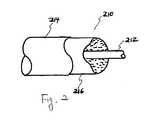
- FIG. 2is a schematic diagram of a distributed charge according to a preferred embodiment of the present invention.
- FIG. 3is a schematic diagram of an inflatable system according to a preferred embodiment of the present invention.
- FIGS. 4 and 5are schematic diagrams of an exemplary implementation of the present invention.
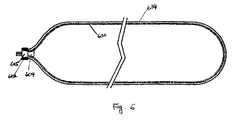
- FIG. 6is a schematic diagram of an inflatable system according to another embodiment of the present invention.
- FIG. 1shows a distributed charge assembly according to a preferred embodiment of the present invention.
- distributed charge assembly 100includes a distributed charge 102 and a housing body 104 .
- distributed charge 102is enclosed in a sheath 103 .
- distributed charge assembly 100also includes an end cap seal 116 .
- End cap seal 116can be in form of o-ring, gaskets or other appropriate forms which serve to seal against moisture and contamination.
- end cap seal 116can be made of rubber, RTV and/or metals.
- Housing body 104includes an initiator 105 , connector pins 106 and a sustainer 107 .
- Connector pins 106are used to electrically connect distributed charge assembly 100 to a crash sensor or other activator.
- Initiator 105includes an electronic squib, such as the electric squibs used to initiate deployment of an automotive air bag.
- Sustainer 107can assume any desired state, such as gas, solid or liquid, and desired shape.
- the sustainercan be in form of pills, tablets or compressed gas.
- the sustainercan be formed by extrusion and cut to the appropriate length. In the embodiment shown in FIG. 1 , sustainer 107 is in form of pills.
- Nitrocellulose or guadinium nitrate compositionfor example, can be used as sustainer 107 .
- sustainer 107exhibits relatively long burn times (typically between 50 to 500 ms, preferably 200 ms).
- Sustainer 107is held and supported by a retaining ring 108 and a spring 109 in housing body 104 .
- Spring 109accommodates for different loads of sustainer 107 to suit the specific application. Other elastic materials or mechanisms can be used as alternatives to spring 109 .
- Housing body 104also includes a nozzle screen 110 and a ferrule 112 .
- Ferrule 112controls the output and joins housing body 104 to distributed charge 102 by mechanically holding the distributed charge.
- Nozzle screen 110retains sustainer 107 in the housing body 104 .
- housing body 104may include a booster 114 to help the ignition of the distributed charge.
- boron potassium nitrate (BKNO3)can be used as booster 114 .
- Distributed charge 102can be a solid monolithic block of pyrotechnic materials formed into the desired configuration using binders.
- the pyrotechnic material(with or with out binders) can be enclosed by an exterior sheath, layer or coating for environmental protection.
- the base distributed charge inflatormay be a mixture of ammonium, guadinium, and/or triaminoguadinium salts of decahydrodecaboric acid and inorganic oxidizers such as ammonium nitrate and/or potassium nitrate.
- Representative compositionsinclude 5-30% by weight of the decahydrodecaborate salt and 70-90% by weight of the nitrate salt.
- the additional materialsmay be used to coat, wrap, tape, or sheath the base distributed charge inflator prior to installation of the overall distributed charge inflator in the inflatable system.
- the distributed chargecan include a core of ignition material and a sheath.
- FIG. 2shows a distributed charge 210 including a core of ignition material 212 and a sheath 214 .
- distributed charge 210may, also an alternatively, include a gas generating layer or coating 216 .
- Ignition material 212is a moldable, formable, or extrudable rapidly burning pyrotechnic material, such as hydroborate fuel with various nitrate oxidizers (e.g., Rapid Deflagrating Cord (RDC) manufactured by Teledyne McCormick-Selph, Inc.), or secondary explosives loaded into a metal sheath (e.g., Mild Detonating Fuse (MDF), also known as Low Energy Detonating Cord or LEDC, manufactured by the Ensign Bickford Company of Simsbury, Conn.), as disclosed in the U.S. Pat. No. 6,062,143, which is incorporated herein by reference.
- RDCRapid Deflagrating Cord
- MDFMild Detonating Fuse
- LEDCLow Energy Detonating Cord
- Materials for the optional gas-generating layer or coating 216include alkali metal azides and organic azides with polymer binders, oxidizers, and metals used as the coating sheath or binder.
- alkali metal azides and organic azideswith polymer binders, oxidizers, and metals used as the coating sheath or binder.
- one possible composition for a particular applicationmight be a mixture of 20-50% by weight sodium azide, 25-35% by weight of potassium nitrate, 10-15% by weight of a fluoroelastomer binder, and 15-25% by weight of magnesium.
- energetic propellants and explosivescan also be added to the distributed charge composition or to the coating or wrapping.
- BTTNbutanetriol trinitrate
- PETNpentaerythritol tetranitrate
- RDXcyclotrimethylene trinitramine
- HMXcyclotetramethylene tetranitramine
- MTNmetriol trinitrate
- trinitrotoluenenitroglycerine
- inorganic oxidizershexanitrostilbene (HNS), dipicramid (DIPAM), or inorganic oxidizers such as potassium nitrate, with metals such as magnesium
- the energetic propellants and the explosivescan be used as a sustainer.
- Polymer binders which may be used to bind the distributed chargeinclude: fluoroelastomers, crosslinked polybutadiene rubber, crosslinked polyacrylic rubber, crosslinked polyurethane elastomers, and polyvinyl alcohol/acetate.
- Energetic or gas-generating polymers which may be employed in the distributed charge assemblyinclude: glycidyl nitrate polymers, glycidyl azide polymer, polytetrazoles, polytriazoles, nitrocellulose, dinitropolystyrene, nitrated polybutadienes, and nitrated polyethers.
- the environmentally-sealed sheath 214 enclosing the distributed chargemay be fabricated from ductile, easily extrudable metals such as tin (preferably) or silver, antimony or copper, or plastics such as polyethylene, polyurethane elastomer or fluoroelastomers.
- the sheathis designed to encapsulate and protect the energetic gas-generating materials to allow uniform vaporization or burning.
- the sheathsplits open or vaporizes following the ignition of the distributed charge.
- the distributed charge, the gas generating layer, and the sheathcan be formed into a wide variety of shapes and sizes to suit the specific application.
- FIG. 3shows an inflatable system according to a preferred embodiment of the present invention.
- inflatable system 310includes an inflatable component 334 and a distributed charge assembly 300 including a distributed charge 302 and a housing body 304 .
- Housing body 304includes an initiator 305 and a sustainer 307 .
- Inflatable system 310receives an electric signal from an activator 330 along a wire 332 , when a crash sensor or other activator determines that the inflatable component must be deployed.
- initiator 305ignites distributed charge 302 , generates inflating gas, thus deploys inflatable component 334 .
- the explosion of initiator 305is effective enough to initiate combustion of both sustainer 307 and distributed charge 302 .
- Combustion of distributed charge 302generates a high volume of gas which ruptures sheath 303 and inflates inflatable component 334 from stowed to deployed conditions.
- the distributed chargetypically combusts over a relatively short time interval (typically between 1 and 20 ms, preferably 5 ms).
- the sustaineris provided to combust over a relatively longer interval (typically between 50 to 500 ms, preferably 200 ms).
- the gas generated from combustion of the sustainercan be vented from the housing through ferrule 312 .
- a booster 314can be included in housing body 300 to assist ignition of the distributed charge.
- the length of the time intervals over which the distributed charge and the sustainer are combustedcan be selected for the particular application.
- the inflatable component for a side-impact protection system for a sports utility vehicleneeds to become fully inflated within 15 ms, and needs to remain inflated for at least 2.5 seconds, preferably as long as 7 seconds or more so that it can protect its occupants in a rollover.
- the inflatable component for front impact protection systemshould become fully inflated within 30 ms and should remain inflated for 100 ms.
- the inflatable cushion, bag, flotation device, or other inflatable structure which the distributed charge inflator is designed to deploymay be composed of fabrics such as polyester, nylon, aramid, or other fibers; or such fabrics coated with polyurethane, silicone, or other materials; bladders fabricated from polyurethane elastomers, silicone elastomers, neoprene or vinyl rubbers; or such bladder materials contained in braided fabrics such as nylon, aramid, mylar, polyester, or other thin film materials.
- the distributed charge inflatormay be manufactured in various sizes and configurations, depending upon the inflation requirements of the system for which it is intended. These may range from a foil or thin film, or linear or tubular shaped charges to broad flat sheets of distributed charge inflator material which may be cut, trimmed, or otherwise fitted.
- the distributed charge inflator materialwhether in a linear or sheet form, may, in cross-section, be circular, wedge-shaped, diamond-shaped, “L’ shaped, or formed in any number of other configurations. Because of this flexibility and the inherent simplicity of the invention, the distributed charge inflator is easier to install and less expensive to manufacture than gas generator systems currently in use.
- the distributed charge inflatorcan be designed so that, depending on the pattern of distribution of the distributed charge within a given inflatable system, the rate at which different distributed charge inflator sections are ignited, and the number or location of the electronic squibs used to ignite the material, variable inflation rates and effective total gas volumes may be achieved.
- the materials used for the distributed charge inflatorshould be flexible and pliable, such that they will not fracture or flow under normal operating conditions.
- FIGS. 4 and 5show exemplary implementations of the present invention.
- distributed charge assemblycan be placed inside of inflatable component 434 and sealed so that the pins of the electronic squib 406 or other initiator are exposed.
- distributed charge assemblycan be sealed inside of the inflatable component using, for example, band clamp 550 , as shown in FIG. 5 .
- FIG. 6shows an inflatable system according to another embodiment of the present invention.
- inflatable component 634is internally coated with a gas generating material 630 .
- the composition of the gas generating materialis the same as the composition of the distributed charge inflator described above, except that no external sheath is used.
- the gas generating materialcan be applied to the inflatable component either prior to or after the air bag is assembled.
- Initiator 605provides ignition of gas generating material 630 and sustainer 604 .
- Clamp 612seals the inflatable component 634 to initiator 605 .
- the specificationmay have presented the method and/or process of the present invention as a particular sequence of steps. However, to the extent that the method or process does not rely on the particular order of steps set forth herein, the method or process should not be limited to the particular sequence of steps described. As one of ordinary skill in the art would appreciate, other sequences of steps may be possible. Therefore, the particular order of the steps set forth in the specification should not be construed as limitations on the claims. In addition, the claims directed to the method and/or process of the present invention should not be limited to the performance of their steps in the order written, and one skilled in the art can readily appreciate that the sequences may be varied and still remain within the spirit and scope of the present invention.
Landscapes
- Engineering & Computer Science (AREA)
- Mechanical Engineering (AREA)
- Chemical & Material Sciences (AREA)
- Physics & Mathematics (AREA)
- Fluid Mechanics (AREA)
- Chemical Kinetics & Catalysis (AREA)
- Combustion & Propulsion (AREA)
- Organic Chemistry (AREA)
- Air Bags (AREA)
- Feeding, Discharge, Calcimining, Fusing, And Gas-Generation Devices (AREA)
Abstract
Description
Claims (12)
Priority Applications (11)
| Application Number | Priority Date | Filing Date | Title |
|---|---|---|---|
| US10/146,933US6886469B2 (en) | 2002-05-17 | 2002-05-17 | Distributed charge inflator system |
| US10/224,435US7162958B2 (en) | 2002-05-17 | 2002-08-21 | Distributed charge inflator system |
| PCT/US2003/015278WO2003097382A2 (en) | 2002-05-17 | 2003-05-16 | Distributed charge inflator system |
| EP03728935AEP1509409B1 (en) | 2002-05-17 | 2003-05-16 | Distributed charge inflator system |
| JP2004504745AJP2005525963A (en) | 2002-05-17 | 2003-05-16 | Distributed charge inflator device |
| ES03728935TES2290463T3 (en) | 2002-05-17 | 2003-05-16 | INFLATOR SYSTEM FOR DISTRIBUTED LOAD. |
| KR1020047018507AKR100665766B1 (en) | 2002-05-17 | 2003-05-16 | Dispensing charge inflator system |
| AU2003234593AAU2003234593A1 (en) | 2002-05-17 | 2003-05-16 | Distributed charge inflator system |
| AT03728935TATE366673T1 (en) | 2002-05-17 | 2003-05-16 | DISTRIBUTED CHARGE INFLATION SYSTEM |
| DE60314873TDE60314873T2 (en) | 2002-05-17 | 2003-05-16 | INFLATION SYSTEM WITH DISTRIBUTED CHARGE |
| US10/458,179US7137341B2 (en) | 2002-05-17 | 2003-06-11 | Distributed charge inflator system |
Applications Claiming Priority (1)
| Application Number | Priority Date | Filing Date | Title |
|---|---|---|---|
| US10/146,933US6886469B2 (en) | 2002-05-17 | 2002-05-17 | Distributed charge inflator system |
Related Child Applications (2)
| Application Number | Title | Priority Date | Filing Date |
|---|---|---|---|
| US10/224,435Continuation-In-PartUS7162958B2 (en) | 2002-05-17 | 2002-08-21 | Distributed charge inflator system |
| US10/458,179Continuation-In-PartUS7137341B2 (en) | 2002-05-17 | 2003-06-11 | Distributed charge inflator system |
Publications (2)
| Publication Number | Publication Date |
|---|---|
| US20030213397A1 US20030213397A1 (en) | 2003-11-20 |
| US6886469B2true US6886469B2 (en) | 2005-05-03 |
Family
ID=29418916
Family Applications (1)
| Application Number | Title | Priority Date | Filing Date |
|---|---|---|---|
| US10/146,933Expired - Fee RelatedUS6886469B2 (en) | 2002-05-17 | 2002-05-17 | Distributed charge inflator system |
Country Status (1)
| Country | Link |
|---|---|
| US (1) | US6886469B2 (en) |
Cited By (11)
| Publication number | Priority date | Publication date | Assignee | Title |
|---|---|---|---|---|
| US20030213398A1 (en)* | 2002-05-17 | 2003-11-20 | David Shilliday | Distributed charge inflator system |
| US20040084885A1 (en)* | 2002-09-13 | 2004-05-06 | Burns Sean P. | Inflator |
| US20050217466A1 (en)* | 2004-04-02 | 2005-10-06 | Pyroalliance | Device for cutting a structure in a motor vehicle |
| US20060278119A1 (en)* | 2003-06-11 | 2006-12-14 | David Shilliday | Distributed charge inflator system |
| US7188567B1 (en)* | 1999-11-12 | 2007-03-13 | Zodiac Automotive Us Inc. | Gas generation system |
| US20070272107A1 (en)* | 2003-04-30 | 2007-11-29 | Twarog Joseph W Jr | Energetic Linear Timing Element |
| US20120125219A1 (en)* | 2010-11-24 | 2012-05-24 | Mayville Brian A | Gas generating system |
| US20130305978A1 (en)* | 2012-04-25 | 2013-11-21 | Georgia Tech Research Corporation | Marine vehicle systems and methods |
| US10604259B2 (en) | 2016-01-20 | 2020-03-31 | Amsafe, Inc. | Occupant restraint systems having extending restraints, and associated systems and methods |
| US20240239298A1 (en)* | 2021-09-30 | 2024-07-18 | Daicel Corporation | Airbag device and method for inflating airbag device |
| US12227294B2 (en) | 2011-04-05 | 2025-02-18 | Amsafe, Inc. | Inflatable personal restraint systems |
Families Citing this family (1)
| Publication number | Priority date | Publication date | Assignee | Title |
|---|---|---|---|---|
| DE102018131323A1 (en)* | 2018-12-07 | 2020-06-10 | Trw Airbag Systems Gmbh | Gas generator, gas bag module, vehicle safety system and method for operating a gas generator |
Citations (48)
| Publication number | Priority date | Publication date | Assignee | Title |
|---|---|---|---|---|
| US3532359A (en) | 1968-07-22 | 1970-10-06 | Chrysler Corp | Inflatable device |
| US3606377A (en) | 1968-11-04 | 1971-09-20 | Eaton Yale & Towne | Vehicle crash restraint system |
| US3724870A (en) | 1970-02-18 | 1973-04-03 | Asahi Chemical Ind | Gas-producing device for an inflatable body-protecting bag on a high-speed vehicle |
| US3776570A (en) | 1970-06-16 | 1973-12-04 | Klippan Gmbh | Air bag for motor vehicles for the prevention of injuries in collisions |
| US4200615A (en) | 1976-03-29 | 1980-04-29 | Allied Chemical Corporation | All-pyrotechnic inflator |
| JPH01151066A (en) | 1987-12-09 | 1989-06-13 | Matsushita Electric Ind Co Ltd | Tape recorder |
| US4923212A (en) | 1988-08-17 | 1990-05-08 | Talley Automotive Products, Inc. | Lightweight non-welded inflator unit for automobile airbags |
| US4950458A (en) | 1989-06-22 | 1990-08-21 | Morton International, Inc. | Passenger automotive restraint generator |
| US4998751A (en) | 1990-03-26 | 1991-03-12 | Morton International, Inc. | Two-stage automotive gas bag inflator using igniter material to delay second stage ignition |
| US5078422A (en) | 1990-04-30 | 1992-01-07 | Oea, Inc. | Gas inflator apparatus |
| US5131680A (en) | 1991-03-19 | 1992-07-21 | Trw Vehicle Safety Systems Inc. | Inflator assembly |
| DE4211672A1 (en) | 1992-04-07 | 1993-10-14 | Keiper Recaro Gmbh Co | Seat belts for vehicle seats, in particular motor vehicle seats |
| US5282648A (en) | 1992-06-01 | 1994-02-01 | Simula Inc. | Inflatable body and head restraint system |
| US5299828A (en) | 1992-01-10 | 1994-04-05 | Takata Corporation | Air bag inflator having circumferentially disposed auto ignition material |
| US5322322A (en) | 1993-02-19 | 1994-06-21 | Simula Inc. | Side impact head strike protection system |
| US5397543A (en) | 1993-06-21 | 1995-03-14 | Automotive Systems Laboratory, Inc. | Gas generator |
| US5443286A (en) | 1992-10-09 | 1995-08-22 | Morton International, Inc. | Gas generator for vehicle occupant restraint system |
| US5462307A (en) | 1994-12-27 | 1995-10-31 | General Motors Corporation | Supplemental inflation restraint inflator |
| US5464246A (en) | 1993-02-19 | 1995-11-07 | Simula Inc. | Inflatable tubular cushions for crash protection of seated automobile occupants |
| US5480181A (en) | 1993-02-19 | 1996-01-02 | Simula Inc. | Side impact head strike protection system |
| US5483896A (en) | 1994-07-12 | 1996-01-16 | Morton International, Inc. | Pyrotechnic inflator for an air bag |
| US5588676A (en) | 1994-10-12 | 1996-12-31 | Morton International, Inc. | Stamped metal toroidal hybrid gas generator |
| US5623115A (en) | 1995-05-30 | 1997-04-22 | Morton International, Inc. | Inflator for a vehicle airbag system and a pyrogen igniter used therein |
| US5660412A (en) | 1994-12-12 | 1997-08-26 | Bendix-Atlantic Inflator Company | Hybrid inflator |
| US5670738A (en) | 1996-08-08 | 1997-09-23 | Morton International. Inc. | Hybrid inflator with pop-out diffuser |
| US5738374A (en) | 1995-02-23 | 1998-04-14 | Snc Livbag | Pyrotechnic gas generator for inflatable air-bag of a motor vehicle |
| US5839754A (en) | 1995-06-08 | 1998-11-24 | Honda R&D Co. Ltd. | Multiple stage airbag gas generator |
| EP0888932A1 (en) | 1997-07-04 | 1999-01-07 | Volkswagen Aktiengesellschaft | Method and apparatus to inflate an airbag system of a passenger vehicle |
| US5868424A (en) | 1996-03-06 | 1999-02-09 | Oea, Inc. | Substantially smoke-free and particulate-free inflator for inflatable safety restraint system |
| WO1999038725A2 (en) | 1998-02-03 | 1999-08-05 | Talley Defense Systems, Inc. | Thin inflator and azide polymer composition thereof |
| US5967550A (en) | 1997-10-07 | 1999-10-19 | Trw Inc. | Staged pyrotechnic air bag inflator |
| US5970880A (en) | 1997-03-14 | 1999-10-26 | Livbag S.N.C. | Pyrotechnic gas generator with adaptable flow rate and volume for air bags |
| US6019389A (en) | 1998-03-31 | 2000-02-01 | Trw Vehicle Safety Systems Inc. | Air bag inflator |
| US6032979A (en) | 1998-02-18 | 2000-03-07 | Autoliv Asp, Inc. | Adaptive output inflator |
| US6062143A (en) | 1997-09-08 | 2000-05-16 | Simula, Inc. | Distributed charge inflator system |
| US6066017A (en) | 1998-01-29 | 2000-05-23 | The United States Of America As Represented By The Secretary Of The Navy | Inflatable, noncollapsible, personal flotation device |
| US6073961A (en) | 1998-02-20 | 2000-06-13 | Breed Automotive Technology, Inc. | Inflatable side airbag curtain module |
| US6095559A (en) | 1998-07-23 | 2000-08-01 | Autoliv Asp, Inc. | Chemical cooling of airbag inflation gases |
| US6106010A (en) | 1998-03-31 | 2000-08-22 | Trw Vehicle Safety Systems Inc. | Vehicle occupant protection system having a dual stage inflator |
| US6119474A (en) | 1997-08-26 | 2000-09-19 | Augustine Medical, Inc. | Inflatable thermal blanket for convectively and evaporatively cooling a body |
| EP1069005A2 (en) | 1999-07-16 | 2001-01-17 | Johnson Controls Technology Company | Assembly with trim cover for housing an inflatable airbag |
| US6227562B1 (en) | 1999-02-26 | 2001-05-08 | Trw Inc. | Stored gas inflator assembly |
| WO2001034516A2 (en) | 1999-11-12 | 2001-05-17 | General Dynamics Ots (Aerospace), Inc. | Gas generation system |
| US6237950B1 (en) | 1999-07-26 | 2001-05-29 | Trw Vehicle Safety Systems Inc. | Staged air bag inflator |
| US6308984B1 (en) | 1999-04-29 | 2001-10-30 | Trw Occupant Restraint Systems Gmbh & Co. Kg | Gas generator and device for inflating a vehicle occupant restraint system |
| US6460873B1 (en) | 1999-09-24 | 2002-10-08 | Livbag Snc | Inflatable metal structure with built-in pyrotechnic charge |
| US20030075909A1 (en) | 2001-10-19 | 2003-04-24 | Livbag Snc | Hybrid gas generator unit for inflating an airbag used in motor vehicle safety |
| US20030075904A1 (en) | 2001-10-19 | 2003-04-24 | Livbag Snc | Hybrid gas generator unit used in motor vehicle safety for inflating a side airbag |
- 2002
- 2002-05-17USUS10/146,933patent/US6886469B2/ennot_activeExpired - Fee Related
Patent Citations (50)
| Publication number | Priority date | Publication date | Assignee | Title |
|---|---|---|---|---|
| US3532359A (en) | 1968-07-22 | 1970-10-06 | Chrysler Corp | Inflatable device |
| US3606377A (en) | 1968-11-04 | 1971-09-20 | Eaton Yale & Towne | Vehicle crash restraint system |
| US3724870A (en) | 1970-02-18 | 1973-04-03 | Asahi Chemical Ind | Gas-producing device for an inflatable body-protecting bag on a high-speed vehicle |
| US3776570A (en) | 1970-06-16 | 1973-12-04 | Klippan Gmbh | Air bag for motor vehicles for the prevention of injuries in collisions |
| US4200615A (en) | 1976-03-29 | 1980-04-29 | Allied Chemical Corporation | All-pyrotechnic inflator |
| JPH01151066A (en) | 1987-12-09 | 1989-06-13 | Matsushita Electric Ind Co Ltd | Tape recorder |
| US4923212A (en) | 1988-08-17 | 1990-05-08 | Talley Automotive Products, Inc. | Lightweight non-welded inflator unit for automobile airbags |
| US4950458A (en) | 1989-06-22 | 1990-08-21 | Morton International, Inc. | Passenger automotive restraint generator |
| US4998751A (en) | 1990-03-26 | 1991-03-12 | Morton International, Inc. | Two-stage automotive gas bag inflator using igniter material to delay second stage ignition |
| US5078422A (en) | 1990-04-30 | 1992-01-07 | Oea, Inc. | Gas inflator apparatus |
| US5131680A (en) | 1991-03-19 | 1992-07-21 | Trw Vehicle Safety Systems Inc. | Inflator assembly |
| US5299828A (en) | 1992-01-10 | 1994-04-05 | Takata Corporation | Air bag inflator having circumferentially disposed auto ignition material |
| DE4211672A1 (en) | 1992-04-07 | 1993-10-14 | Keiper Recaro Gmbh Co | Seat belts for vehicle seats, in particular motor vehicle seats |
| US5282648A (en) | 1992-06-01 | 1994-02-01 | Simula Inc. | Inflatable body and head restraint system |
| US5443286A (en) | 1992-10-09 | 1995-08-22 | Morton International, Inc. | Gas generator for vehicle occupant restraint system |
| US5322322A (en) | 1993-02-19 | 1994-06-21 | Simula Inc. | Side impact head strike protection system |
| US5464246A (en) | 1993-02-19 | 1995-11-07 | Simula Inc. | Inflatable tubular cushions for crash protection of seated automobile occupants |
| US5480181A (en) | 1993-02-19 | 1996-01-02 | Simula Inc. | Side impact head strike protection system |
| US5397543A (en) | 1993-06-21 | 1995-03-14 | Automotive Systems Laboratory, Inc. | Gas generator |
| US5483896A (en) | 1994-07-12 | 1996-01-16 | Morton International, Inc. | Pyrotechnic inflator for an air bag |
| US5588676A (en) | 1994-10-12 | 1996-12-31 | Morton International, Inc. | Stamped metal toroidal hybrid gas generator |
| US5660412A (en) | 1994-12-12 | 1997-08-26 | Bendix-Atlantic Inflator Company | Hybrid inflator |
| US5462307A (en) | 1994-12-27 | 1995-10-31 | General Motors Corporation | Supplemental inflation restraint inflator |
| US5738374A (en) | 1995-02-23 | 1998-04-14 | Snc Livbag | Pyrotechnic gas generator for inflatable air-bag of a motor vehicle |
| US5623115A (en) | 1995-05-30 | 1997-04-22 | Morton International, Inc. | Inflator for a vehicle airbag system and a pyrogen igniter used therein |
| US5839754A (en) | 1995-06-08 | 1998-11-24 | Honda R&D Co. Ltd. | Multiple stage airbag gas generator |
| US5868424A (en) | 1996-03-06 | 1999-02-09 | Oea, Inc. | Substantially smoke-free and particulate-free inflator for inflatable safety restraint system |
| US5670738A (en) | 1996-08-08 | 1997-09-23 | Morton International. Inc. | Hybrid inflator with pop-out diffuser |
| US5970880A (en) | 1997-03-14 | 1999-10-26 | Livbag S.N.C. | Pyrotechnic gas generator with adaptable flow rate and volume for air bags |
| EP0888932A1 (en) | 1997-07-04 | 1999-01-07 | Volkswagen Aktiengesellschaft | Method and apparatus to inflate an airbag system of a passenger vehicle |
| US6119474A (en) | 1997-08-26 | 2000-09-19 | Augustine Medical, Inc. | Inflatable thermal blanket for convectively and evaporatively cooling a body |
| US6062143A (en) | 1997-09-08 | 2000-05-16 | Simula, Inc. | Distributed charge inflator system |
| US5967550A (en) | 1997-10-07 | 1999-10-19 | Trw Inc. | Staged pyrotechnic air bag inflator |
| US6066017A (en) | 1998-01-29 | 2000-05-23 | The United States Of America As Represented By The Secretary Of The Navy | Inflatable, noncollapsible, personal flotation device |
| WO1999038725A2 (en) | 1998-02-03 | 1999-08-05 | Talley Defense Systems, Inc. | Thin inflator and azide polymer composition thereof |
| US6032979A (en) | 1998-02-18 | 2000-03-07 | Autoliv Asp, Inc. | Adaptive output inflator |
| US6032979C1 (en) | 1998-02-18 | 2001-10-16 | Autoliv Asp Inc | Adaptive output inflator |
| US6073961A (en) | 1998-02-20 | 2000-06-13 | Breed Automotive Technology, Inc. | Inflatable side airbag curtain module |
| US6237941B1 (en) | 1998-02-20 | 2001-05-29 | Breed Automotive Technology, Inc. | Inflatable side airbag curtain module |
| US6106010A (en) | 1998-03-31 | 2000-08-22 | Trw Vehicle Safety Systems Inc. | Vehicle occupant protection system having a dual stage inflator |
| US6019389A (en) | 1998-03-31 | 2000-02-01 | Trw Vehicle Safety Systems Inc. | Air bag inflator |
| US6095559A (en) | 1998-07-23 | 2000-08-01 | Autoliv Asp, Inc. | Chemical cooling of airbag inflation gases |
| US6227562B1 (en) | 1999-02-26 | 2001-05-08 | Trw Inc. | Stored gas inflator assembly |
| US6308984B1 (en) | 1999-04-29 | 2001-10-30 | Trw Occupant Restraint Systems Gmbh & Co. Kg | Gas generator and device for inflating a vehicle occupant restraint system |
| EP1069005A2 (en) | 1999-07-16 | 2001-01-17 | Johnson Controls Technology Company | Assembly with trim cover for housing an inflatable airbag |
| US6237950B1 (en) | 1999-07-26 | 2001-05-29 | Trw Vehicle Safety Systems Inc. | Staged air bag inflator |
| US6460873B1 (en) | 1999-09-24 | 2002-10-08 | Livbag Snc | Inflatable metal structure with built-in pyrotechnic charge |
| WO2001034516A2 (en) | 1999-11-12 | 2001-05-17 | General Dynamics Ots (Aerospace), Inc. | Gas generation system |
| US20030075909A1 (en) | 2001-10-19 | 2003-04-24 | Livbag Snc | Hybrid gas generator unit for inflating an airbag used in motor vehicle safety |
| US20030075904A1 (en) | 2001-10-19 | 2003-04-24 | Livbag Snc | Hybrid gas generator unit used in motor vehicle safety for inflating a side airbag |
Cited By (17)
| Publication number | Priority date | Publication date | Assignee | Title |
|---|---|---|---|---|
| US7188567B1 (en)* | 1999-11-12 | 2007-03-13 | Zodiac Automotive Us Inc. | Gas generation system |
| US7162958B2 (en) | 2002-05-17 | 2007-01-16 | Zodiac Automotive Us Inc. | Distributed charge inflator system |
| US20030213398A1 (en)* | 2002-05-17 | 2003-11-20 | David Shilliday | Distributed charge inflator system |
| US20040084885A1 (en)* | 2002-09-13 | 2004-05-06 | Burns Sean P. | Inflator |
| US7097203B2 (en) | 2002-09-13 | 2006-08-29 | Automotive Systems Laboratory, Inc. | Inflator |
| US8327766B2 (en)* | 2003-04-30 | 2012-12-11 | Dyno Nobel Inc. | Energetic linear timing element |
| US20070272107A1 (en)* | 2003-04-30 | 2007-11-29 | Twarog Joseph W Jr | Energetic Linear Timing Element |
| US20060278119A1 (en)* | 2003-06-11 | 2006-12-14 | David Shilliday | Distributed charge inflator system |
| US20050217466A1 (en)* | 2004-04-02 | 2005-10-06 | Pyroalliance | Device for cutting a structure in a motor vehicle |
| US20120125219A1 (en)* | 2010-11-24 | 2012-05-24 | Mayville Brian A | Gas generating system |
| US9051226B2 (en)* | 2010-11-24 | 2015-06-09 | Tk Holdings Inc. | Gas generating system |
| US12227294B2 (en) | 2011-04-05 | 2025-02-18 | Amsafe, Inc. | Inflatable personal restraint systems |
| US20130305978A1 (en)* | 2012-04-25 | 2013-11-21 | Georgia Tech Research Corporation | Marine vehicle systems and methods |
| US9032900B2 (en)* | 2012-04-25 | 2015-05-19 | Georgia Tech Research Corporation | Marine vehicle systems and methods |
| US10604259B2 (en) | 2016-01-20 | 2020-03-31 | Amsafe, Inc. | Occupant restraint systems having extending restraints, and associated systems and methods |
| US20240239298A1 (en)* | 2021-09-30 | 2024-07-18 | Daicel Corporation | Airbag device and method for inflating airbag device |
| US12304418B2 (en)* | 2021-09-30 | 2025-05-20 | Daicel Corporation | Airbag device and method for inflating airbag device |
Also Published As
| Publication number | Publication date |
|---|---|
| US20030213397A1 (en) | 2003-11-20 |
Similar Documents
| Publication | Publication Date | Title |
|---|---|---|
| US6062143A (en) | Distributed charge inflator system | |
| EP0825074B1 (en) | Air bag inflator | |
| KR100501963B1 (en) | Progressive deployment of airbags and chemical gunpowder for their implementation | |
| EP1945597B1 (en) | Gas generation system | |
| US7097203B2 (en) | Inflator | |
| EP1658204A1 (en) | Pyrotechnique side impact inflator | |
| US6886469B2 (en) | Distributed charge inflator system | |
| US6368431B2 (en) | Air bag inflator | |
| WO2000032447A9 (en) | Pyrotechnic inflator for a vehicle | |
| US7137341B2 (en) | Distributed charge inflator system | |
| US7162958B2 (en) | Distributed charge inflator system | |
| WO2001025058A1 (en) | Hybrid inflator | |
| US7188567B1 (en) | Gas generation system | |
| MXPA99004284A (en) | Distributed charge inflator system |
Legal Events
| Date | Code | Title | Description |
|---|---|---|---|
| AS | Assignment | Owner name:SIMULA, INC., ARIZONA Free format text:ASSIGNMENT OF ASSIGNORS INTEREST;ASSIGNORS:SHILLIDAY, DAVID;SCAVEN, GREGORY J.;FITZGERALD, KEVIN;REEL/FRAME:013198/0598 Effective date:20020807 | |
| AS | Assignment | Owner name:ALLIED CAPITAL CORPORATION, ILLINOIS Free format text:SECURITY INTEREST;ASSIGNOR:SIMULA, INC.;REEL/FRAME:013858/0845 Effective date:20010926 | |
| AS | Assignment | Owner name:ZODIAC AUTOMOTIVE US INC., ARIZONA Free format text:ASSIGNMENT OF ASSIGNORS INTEREST;ASSIGNOR:SIMULA, INC.;REEL/FRAME:014455/0043 Effective date:20030722 | |
| FPAY | Fee payment | Year of fee payment:4 | |
| FEPP | Fee payment procedure | Free format text:PAYOR NUMBER ASSIGNED (ORIGINAL EVENT CODE: ASPN); ENTITY STATUS OF PATENT OWNER: LARGE ENTITY Free format text:PAYER NUMBER DE-ASSIGNED (ORIGINAL EVENT CODE: RMPN); ENTITY STATUS OF PATENT OWNER: LARGE ENTITY | |
| REMI | Maintenance fee reminder mailed | ||
| LAPS | Lapse for failure to pay maintenance fees | ||
| STCH | Information on status: patent discontinuation | Free format text:PATENT EXPIRED DUE TO NONPAYMENT OF MAINTENANCE FEES UNDER 37 CFR 1.362 | |
| FP | Lapsed due to failure to pay maintenance fee | Effective date:20130503 |