US6886181B1 - Extended distribution of ADSL signals - Google Patents
Extended distribution of ADSL signalsDownload PDFInfo
- Publication number
- US6886181B1 US6886181B1US09/612,445US61244500AUS6886181B1US 6886181 B1US6886181 B1US 6886181B1US 61244500 AUS61244500 AUS 61244500AUS 6886181 B1US6886181 B1US 6886181B1
- Authority
- US
- United States
- Prior art keywords
- signals
- adsl
- frequency
- central office
- field cabinet
- Prior art date
- Legal status (The legal status is an assumption and is not a legal conclusion. Google has not performed a legal analysis and makes no representation as to the accuracy of the status listed.)
- Expired - Fee Related, expires
Links
- 101150012579ADSL geneProteins0.000titleclaims36
- 102100020775Adenylosuccinate lyaseHuman genes0.000titleclaims36
- 108700040193Adenylosuccinate lyasesProteins0.000titleclaims36
- 230000005540biological transmissionEffects0.000claimsabstractdescription26
- 239000000835fiberSubstances0.000claimsabstractdescription19
- 238000013519translationMethods0.000claimsdescription17
- 230000003287optical effectEffects0.000claimsdescription11
- 239000004020conductorSubstances0.000claimsdescription4
- 238000011144upstream manufacturingMethods0.000claimsdescription4
- 238000001514detection methodMethods0.000claimsdescription2
- 230000000694effectsEffects0.000claimsdescription2
- 239000000969carrierSubstances0.000claims1
- 230000006854communicationEffects0.000abstractdescription13
- 238000004891communicationMethods0.000abstractdescription13
- 238000000034methodMethods0.000abstractdescription4
- 239000013307optical fiberSubstances0.000abstractdescription4
- 230000000717retained effectEffects0.000abstract1
- 238000005516engineering processMethods0.000description7
- 230000007175bidirectional communicationEffects0.000description3
- 238000009434installationMethods0.000description2
- 230000015556catabolic processEffects0.000description1
- 238000006243chemical reactionMethods0.000description1
- 238000010276constructionMethods0.000description1
- 238000006731degradation reactionMethods0.000description1
- 238000011161developmentMethods0.000description1
- 230000007613environmental effectEffects0.000description1
- RGNPBRKPHBKNKX-UHFFFAOYSA-NhexaflumuronChemical compoundC1=C(Cl)C(OC(F)(F)C(F)F)=C(Cl)C=C1NC(=O)NC(=O)C1=C(F)C=CC=C1FRGNPBRKPHBKNKX-UHFFFAOYSA-N0.000description1
- 238000012986modificationMethods0.000description1
- 230000004048modificationEffects0.000description1
- NJPPVKZQTLUDBO-UHFFFAOYSA-NnovaluronChemical compoundC1=C(Cl)C(OC(F)(F)C(OC(F)(F)F)F)=CC=C1NC(=O)NC(=O)C1=C(F)C=CC=C1FNJPPVKZQTLUDBO-UHFFFAOYSA-N0.000description1
- 238000001228spectrumMethods0.000description1
- OIWCYIUQAVBPGV-DAQGAKHBSA-N{1-O-hexadecanoyl-2-O-[(Z)-octadec-9-enoyl]-sn-glycero-3-phospho}serineChemical compoundCCCCCCCCCCCCCCCC(=O)OC[C@H](COP(O)(=O)OC[C@H](N)C(O)=O)OC(=O)CCCCCCC\C=C/CCCCCCCCOIWCYIUQAVBPGV-DAQGAKHBSA-N0.000description1
Images


Classifications
- H—ELECTRICITY
- H04—ELECTRIC COMMUNICATION TECHNIQUE
- H04L—TRANSMISSION OF DIGITAL INFORMATION, e.g. TELEGRAPHIC COMMUNICATION
- H04L25/00—Baseband systems
- H04L25/38—Synchronous or start-stop systems, e.g. for Baudot code
- H04L25/40—Transmitting circuits; Receiving circuits
- H04L25/49—Transmitting circuits; Receiving circuits using code conversion at the transmitter; using predistortion; using insertion of idle bits for obtaining a desired frequency spectrum; using three or more amplitude levels ; Baseband coding techniques specific to data transmission systems
- H04L25/4906—Transmitting circuits; Receiving circuits using code conversion at the transmitter; using predistortion; using insertion of idle bits for obtaining a desired frequency spectrum; using three or more amplitude levels ; Baseband coding techniques specific to data transmission systems using binary codes
- H04L25/4908—Transmitting circuits; Receiving circuits using code conversion at the transmitter; using predistortion; using insertion of idle bits for obtaining a desired frequency spectrum; using three or more amplitude levels ; Baseband coding techniques specific to data transmission systems using binary codes using mBnB codes
- H—ELECTRICITY
- H04—ELECTRIC COMMUNICATION TECHNIQUE
- H04Q—SELECTING
- H04Q11/00—Selecting arrangements for multiplex systems
- H04Q11/04—Selecting arrangements for multiplex systems for time-division multiplexing
- H—ELECTRICITY
- H04—ELECTRIC COMMUNICATION TECHNIQUE
- H04Q—SELECTING
- H04Q2213/00—Indexing scheme relating to selecting arrangements in general and for multiplex systems
- H04Q2213/1301—Optical transmission, optical switches
- H—ELECTRICITY
- H04—ELECTRIC COMMUNICATION TECHNIQUE
- H04Q—SELECTING
- H04Q2213/00—Indexing scheme relating to selecting arrangements in general and for multiplex systems
- H04Q2213/13034—A/D conversion, code compression/expansion
- H—ELECTRICITY
- H04—ELECTRIC COMMUNICATION TECHNIQUE
- H04Q—SELECTING
- H04Q2213/00—Indexing scheme relating to selecting arrangements in general and for multiplex systems
- H04Q2213/13039—Asymmetrical two-way transmission, e.g. ADSL, HDSL
- H—ELECTRICITY
- H04—ELECTRIC COMMUNICATION TECHNIQUE
- H04Q—SELECTING
- H04Q2213/00—Indexing scheme relating to selecting arrangements in general and for multiplex systems
- H04Q2213/1305—Software aspects
- H—ELECTRICITY
- H04—ELECTRIC COMMUNICATION TECHNIQUE
- H04Q—SELECTING
- H04Q2213/00—Indexing scheme relating to selecting arrangements in general and for multiplex systems
- H04Q2213/1309—Apparatus individually associated with a subscriber line, line circuits
- H—ELECTRICITY
- H04—ELECTRIC COMMUNICATION TECHNIQUE
- H04Q—SELECTING
- H04Q2213/00—Indexing scheme relating to selecting arrangements in general and for multiplex systems
- H04Q2213/13099—Loop multiplexer
- H—ELECTRICITY
- H04—ELECTRIC COMMUNICATION TECHNIQUE
- H04Q—SELECTING
- H04Q2213/00—Indexing scheme relating to selecting arrangements in general and for multiplex systems
- H04Q2213/1319—Amplifier, attenuation circuit, echo suppressor
- H—ELECTRICITY
- H04—ELECTRIC COMMUNICATION TECHNIQUE
- H04Q—SELECTING
- H04Q2213/00—Indexing scheme relating to selecting arrangements in general and for multiplex systems
- H04Q2213/13214—Clock signals
- H—ELECTRICITY
- H04—ELECTRIC COMMUNICATION TECHNIQUE
- H04Q—SELECTING
- H04Q2213/00—Indexing scheme relating to selecting arrangements in general and for multiplex systems
- H04Q2213/13291—Frequency division multiplexing, FDM
- H—ELECTRICITY
- H04—ELECTRIC COMMUNICATION TECHNIQUE
- H04Q—SELECTING
- H04Q2213/00—Indexing scheme relating to selecting arrangements in general and for multiplex systems
- H04Q2213/13292—Time division multiplexing, TDM
- H—ELECTRICITY
- H04—ELECTRIC COMMUNICATION TECHNIQUE
- H04Q—SELECTING
- H04Q2213/00—Indexing scheme relating to selecting arrangements in general and for multiplex systems
- H04Q2213/13305—Transistors, semiconductors in general
- H—ELECTRICITY
- H04—ELECTRIC COMMUNICATION TECHNIQUE
- H04Q—SELECTING
- H04Q2213/00—Indexing scheme relating to selecting arrangements in general and for multiplex systems
- H04Q2213/1332—Logic circuits
- H—ELECTRICITY
- H04—ELECTRIC COMMUNICATION TECHNIQUE
- H04Q—SELECTING
- H04Q2213/00—Indexing scheme relating to selecting arrangements in general and for multiplex systems
- H04Q2213/13322—Integrated circuits
- H—ELECTRICITY
- H04—ELECTRIC COMMUNICATION TECHNIQUE
- H04Q—SELECTING
- H04Q2213/00—Indexing scheme relating to selecting arrangements in general and for multiplex systems
- H04Q2213/13332—Broadband, CATV, dynamic bandwidth allocation
- H—ELECTRICITY
- H04—ELECTRIC COMMUNICATION TECHNIQUE
- H04Q—SELECTING
- H04Q2213/00—Indexing scheme relating to selecting arrangements in general and for multiplex systems
- H04Q2213/1336—Synchronisation
Definitions
- This inventionrelates to an apparatus for distributing ADSL signals to customer premises from a central office and to a splitter and interface module for use therein.
- ADSLADSL
- HDSLhigh definition SDSL
- VHDSLVHDSL signals
- various forms of ADSL signalscan be used such as DMT, QAM or CAP analog format.
- This informationincludes, in particular telephone service, security and metering services, Internet access and digital video-on-demand services.
- Internet access and specifically video-on-demandrequire very high data rates.
- Optical fiber networkshave the capability of meeting this demand, but do not generally extend to residential customer premises.
- Telephone subscriber linesextend to residential customer premises but have insufficient bandwidth to carry video signals until the recent development of digital video and DSL (digital subscriber line) technology.
- ADSLtypically provides a high data rate channel for transmission in a downstream direction from a telephone CO (central office) to a subscriber, a somewhat lower data rate channel for upstream transmission in addition to POTS (plain old telephone service), via a two-wire telephone subscriber line.
- this technologycan simultaneously communicate Internet data at as well as telephone signals bi-directionally, over a single telephone subscriber line which is referred to as an ADSL loop.
- ADSL technologyfor example the type using multi-carrier modulation, makes it possible to send data at bit rates in excess of 6 Mb/s downstream on telephone subscriber lines.
- ADSL technologyA significant problem in the widespread adoption of ADSL technology is the limited range of transmission. Practical limitations are 4 km from the CO for 1.5 Mb/s service and 2 km from the CO for 6 MB/s service. The telephone operating companies are unable to offer ADSL to many of their customers since the serving radius of each central office exchange is typically up to 5.5 km.
- DSLAMdigital subscriber access multiplexer
- the DSLAMdigitally multiplexes the data from several ADSL loops and provides and interface to a high-speed digital channel connecting to the CO and typically implemented with SONET transmission on optical fiber.
- the RAMcontains relatively bulky equipment that requires power and environmental control.
- the required enclosureis costly since it must be sized for future service growth and this cost is excessive when the RAM serves only a small number of ADSL customers.
- the extension of CO equipment into remote access modulesrequires the deployment of highly skilled service personnel who were previously required only in the CO.
- a representative field cabinetprovides patch connections for approximately 450 residential and business units.
- This inventionutilizes well-established analog transmission equipment to transport ADSL signals from the field cabinet to the CO. For extended distribution of ADSL signals, this eliminates the requirement to place DSLAM equipment in modules that are remote from the CO.
- an apparatus for distributing ADSL signals to customer premises from a central officecomprising:
- the signal splitting couplerincludes a filter that couples to the connectors substantially only voice frequency signals in the frequency band below 4 kHz and couples to the interface and frequency translation units substantially only signals in the frequency range above 20 kHz.
- a filterthat couples to the connectors substantially only voice frequency signals in the frequency band below 4 kHz and couples to the interface and frequency translation units substantially only signals in the frequency range above 20 kHz.
- other schemeswhich avoid the use of a filter are also possible.
- the bi-directional linkincludes a fiber optic link between the field cabinet and the central office, an optical transceiver at the field cabinet and a second optical transceiver at the central office.
- the linkcan also be provided by other known transmission systems which avoid the degradation of the signals including coaxial cable, wireless and microwave systems.
- the linkis a dedicated link unrelated to any local communication systems for cable or the like.
- the bi-directional linkis normally provided by two unidirectional links in the case of fiber optic transmission, the bi-directional communication on the same fiber can be effected by use of two different optical wavelengths. In the case of co-axial cable or CATV transmission, the bi-directional communication on the same cable can be effected by use of two different frequency bands.
- the linkincludes two unidirectional fiber optic links and wherein the interface and frequency translation units each contain a directional hybrid coupler to interface the bi-directional metallic telephone line to the two unidirectional fiber optic links.
- the fiber optic linkincludes a fiber optic cable and a metallic conductor pair for supplying power from the central office to the interface and frequency translation units.
- a fiber optic cable and a metallic conductor pairfor supplying power from the central office to the interface and frequency translation units.
- other techniques for supplying powercan be used including, but not preferably, supply from a local power utility source.
- the frequency translatorsare arranged such that the frequency bands are each located within a respective 6 MHz frequency band communicated on the bi-directional link.
- each frequency translator from the ADSL signals to the frequency bandincludes a CATV modulator arranged to locate the respective ADSL signals within a respective video channel frequency band which is then communicated on the bi-directional link.
- CATV modulatorsare used because they are readily commercially available but other schemes can also be used.
- each frequency translatorincludes a first translator element arranged to translate to an intermediate frequency by double side band transmitted carrier amplitude modulation (AM-DSB-TC) of a radio frequency carrier at the intermediate frequency and wherein the CATV modulator is arranged to translate from the intermediate frequency to the respective video channel frequency band.
- AM-DSB-TCdouble side band transmitted carrier amplitude modulation
- the first translator elementis arranged to effect direct translation from the ADSL signals to the pre-selected frequency band by AM-DSB-TC modulation of a radio frequency carrier.
- each frequency translatorincludes a first tuner element arranged to translate from the pre-selected frequency band to the intermediate frequency band and the tuner to be followed by envelope detection of the AM-DSB-TC signal so as to translate the signal from the intermediate frequency band to the ADSL signal band on the metallic telephone line.
- the bi-directional linkincludes a co-axial cable link.
- the means in each frequency translator communicating the bi-directional ADSL signals via the coaxial cablecomprises at least one transmitter and at least one receiver arranged to transmit and receive the bi-directional signals at respective frequencies.
- the frequency translator at the telephone central officeis tuned to transmit signals at a respective frequency in a first frequency band for a downstream transmission direction on the coaxial cable
- the said frequency translator at field cabinetis tuned to transmit signals at a respective frequency in a second frequency band for an upstream transmission direction on the coaxial cable.
- a splitter and interface modulefor use in the above apparatus, the splitter and interface module at the field cabinet comprising:
- FIG. 1is a schematic illustration of a distribution system for POTS and ADSL signals according to the present invention.
- FIG. 2is a schematic illustration of the field cabinet of FIG. 1 including the splitter and interface module mounted therein.
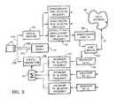
- FIG. 3is a schematic illustration of the additional components at the central office.
- FIG. 1One example of the distribution network is shown in FIG. 1 in which there is provided a plurality of customer locations indicated at 10 , 11 and 12 .
- Some of the customer locationswill be of the arrangement shown at 10 wherein an individual metallic telephone line 13 A within the distribution cable 13 of the telephone system to the customer location is fed into a splitter 14 which acts to separate the voice frequency POTS signals for supply to a POTS terminal 15 from the ADSL signals to an ADSL modem 16 .
- the customer's concernmay have one or more conventional POTS terminals and one or more ADSL modems for communication along the common distribution cable 13 .
- Some of the customer locationssimply require the POPS connection and therefore do not include an ADSL modem or the splitter.
- the distribution systemfurther includes a field cabinet 17 which conventionally comprises a first portion 17 A which simply is a passive construction including terminal connectors 18 an 19 by which the distribution cables 13 are connected to a terminal block 18 and a trunk cable 20 is connected to a second terminal block 19 with jumpers connected to the two terminal blocks to provide the required connections from a trunk cable to the individual subscriber locations.
- a field cabinet 17which conventionally comprises a first portion 17 A which simply is a passive construction including terminal connectors 18 an 19 by which the distribution cables 13 are connected to a terminal block 18 and a trunk cable 20 is connected to a second terminal block 19 with jumpers connected to the two terminal blocks to provide the required connections from a trunk cable to the individual subscriber locations.
- the field cabinetis supplemented by an additional housing 21 which contains a splitter and interface module 22 .
- This moduleis provided for the use of the ADSL customers and is used to separate the signals of those ADSL customers into the separate module from which the POTS signals are separated from the ADSL signals for communication of the POTS signals along the conventional trunk cable 20 while ADSL signals are transmitted through an additional bi-directional link 23 .
- Both the bi-directional link 23 and the trunk cable 20communicate with the central office 25 as separate communication links so that the POTS signals on the trunk cable 20 are communicated to a POTS switching system 26 and the ADSL signals on the link 23 are communicated through an interface module 27 to an ADSL modem 28 connecting to a network 29 .
- the field cabinet 17is shown in more detail and includes the terminal blocks 18 and 19 within the conventional housing section 17 A with some connections 30 extending directly between the blocks 18 and 19 for customers who do not require ADSL services.
- an additional housing 17 BOn top of or at one side of the conventional field cabinet 17 is provided an additional housing 17 B.
- the signals containing both the POTS and ADSL signals to and from the distribution cables 13 for the ADSL customersare connected to the terminal block 32 separately for each of the individual customers along a separate jumper connection 34 .
- the modulecontains a separate splitter and interface module component 36 A, 36 B, 36 C et seq.
- Each of the components 36 A, 36 B, 36 Ccontains for each customer the same functions so that only one of the interface components 36 A is shown in detail.
- splitters of this typeare shown in U.S. Pat. Nos. 5,528,630 and 5,627,501 and are well known to one skilled in the art. The details of the above patents are therefore incorporated herein by reference as examples of splitters which can be used for the splitter arrangement 37 .
- the POTS signals from the low pass filter componentare communicated through a connection 38 to the terminal block 33 and then are supplied through a respective of one jumpers 35 to the respective location on the terminal block 19 thus reconnecting the POTS signals in the same connection that they would normally take from the respective distribution cable 13 to the respective location on the trunk cable 20 .
- the ADSL signals from the splitter 37are supplied through a connector 39 to a hybrid coupler 40 .
- the coupler 40which acts as two/four wire coupler is of a conventional nature widely used in this industry and acts to separate the signals on the two wire connection 39 into a four wire connection provided by a first connection 41 and a second connection 49 for upstream and downstream signals respectively.
- the signals from the customer locationare communicated on the line 41 to a frequency translator for communication on the link 23 .
- the frequency translatorcomprises a first component 42 and a second component 43 which combine to translate the ADSL signals into a respective one of the plurality of video channel frequency bands which are available on the link 23 .
- each customeris allocated a specific one of the interface components 36 A so that the signals from that customer are communicated only to that component and the customer is also allocated a specific frequency band within the available frequency spectrum.
- the frequency bandsare selected to be the same as conventional CATV bands which provides a bandwidth of 6 MHz.
- ADSL signalsuse a portion of this bandwidth in the range 20 kHz to 1.1 MHz.
- the bandwidthmay be greater or smaller depending upon requirements and in some case for example in Europe the CATV bandwidth is conventionally 7 to 8 MHz and yet in other cases the band width may be significantly greater to provide enhanced signal communication capability and up to 20 MHz may be required in such circumstances.
- the frequency translationis effected into two steps using the separate components 42 and 43 .
- the first component 42converts the signals by a double side band transmitted carrier modulation of a radio frequency carrier at an intermediate frequency which selected to be 45.75 MHz.
- the signal translationis effected by AM-DSB-TC modulation of the radio frequency carrier. This modulation technique is again well known to one skilled in the art and suitable components are available commercially.
- the second component 43is a conventional commercially available CATV modulator which translates from the intermediate frequency up to the selected band for that particular customer. Such devices are well known to one skilled in the art and are readily commercially available for use in commercial equipment for CATV communications.
- the frequency translated ADSL signals from the individual customer componentsare communicated to a summing point 44 again of a conventional nature. These signals are then transmitted on the link 23 .
- the linkis a fiber optic cable including two unidirectional cable elements so that the signals from the summing point 44 are transmitted to an optical transmitter 45 for transmission along the cable portion 23 A to the central station.
- the cable portion 23 Bcommunicates signals optically from the central station to the module 22 and particularly to an optical receiver 46 of the module.
- the optical signalsare transmitted to the components of the individual customers where the signals from the particular band allocated to that customer are frequency translated back down from the band to provide the ADSL signals for supply to the line 49 to the coupler 40 .
- the translationis effected in two separate components indicated at 47 and 48 which operate symmetrically to the components 42 and 43 as previously described.
- the signals from the coupler 40thus are bi-directionally communicated through the connector 39 and back through the splitter 37 to the customer location through the respective distribution cable 13 .
- bi-directional linkallows the ADSL signals separated from the POTS signals to be transmitted without appreciable limitation on distance of transmission through the link which is dedicated to the connection between the central station and the particular field cabinet with which the customer's identified are associated.
- the module 22receives power through the fiber optic cable of the link 23 via metallic conductors 23 C and 23 D which connect to the ground line 50 and to a power line 51 respectively.
- the ground and powerare thus provided to the module and to each of the individual components associated with the respective customers.
- a symmetrical arrangement to the module 22 at the field cabinetis provided at the central station.
- a power supply 55for communication of the power and ground to the field cabinet over the metallic conductors 23 C and 23 D of the link 23 .
- the signals on the unidirectional link 23 Aare received by an optical receiver 56 and are supplied to a plurality of down converter components 57 each associated with a respective one of the frequency bands and each arranged to converter the frequencies from that band to provide the ADSL signals associated with the respective customer.
- the down conversionis effected in two steps by components 57 and 58 symmetrical to the components 42 and 43 previously described.
- the ADSL signals of the respective customerare therefore communicated to a respective ADSL modem 60 and through that modem to the data network 62 .
- return signals from the data network 62are received by the ADSL modem and communicated through frequency translation components 63 and 64 to the optical transmitter 66 .
- a single co-axial cablecan be used for communications in both directions and in this case each customer will be allocated a first frequency band for communications in one direction and a second frequency band for communications in the opposite direction.
- An advantage of the inventionis that no specific signal format is required for transmission of DSL signals and that future DSL signal formats can be accommodated by the proposed structure.
- a further advantage of the inventionis that a variety of DSL signals can be accommodated at a specific field cabinet. Furthermore, equipment at the CO for a specific type of DSL transmission can service a number of customers that are associated with a diverse variety of field cabinets.
- the signal coupler unit within the field cabinet splitter and interface moduledoes not interrupt “lifeline” POTS service in the event of power failure or equipment failure.
Landscapes
- Engineering & Computer Science (AREA)
- Computer Networks & Wireless Communication (AREA)
- Physics & Mathematics (AREA)
- Spectroscopy & Molecular Physics (AREA)
- Signal Processing (AREA)
- Telephonic Communication Services (AREA)
Abstract
Description
- U.S. Pat. No. 5,303,229 (Withers et al.) issued 12 Apr. 1994 entitled Optical Network Unit.
- U.S. Pat. No. 5,408,260 (Arnon) issued 18 Apr. 1995 entitled Customer premises ADSL signal distribution arrangement.
- U.S. Pat. No. 5,767,895 (Yashiro and Sasada) issued 16 Jun. 1998 entitled CATV Telephone System.
- U.S. Pat. No. 4,891,694 (Way) issued 2 Jan. 1990 entitled Fiber optic cable television distribution system.
- U.S. Pat. No. 5,917,624 (Wagner) issued 29 Jun. 1999 entitled Method and system for applying fiber to the curb architecture using a broadband gateway at service locations, including homes.
- U.S. Pat. No. 5,940,738 (Rao) issued 17 Aug. 1999 entitled Video pedestal network.
- a central office having a POTS switching system and ADSL terminals that connect to a data network;
- a plurality of customer locations at least some of which have at least one voice frequency POTS terminal and at least one ADSL terminal;
- a field cabinet associated with the plurality of customers;
- a plurality of individual metallic telephone lines each extending from a respective one of the customers to the field cabinet;
- a trunk cable containing a large number of metallic telephone lines and extending from the field cabinet to the central office;
- the field cabinet including a plurality of connections for connecting the individual telephone lines to the trunk cable for connection of signals between the customer locations and the central office;
- the individual metallic telephone lines each being arranged to transmit both voice frequency POTS signals and ADSL signals between the respective customer location and the field cabinet;
- a bi-directional link separate from the trunk cable for the broadband transmission of analog signals in pre-selected frequency bands between the central office and the field cabinet;
- a splitter and interface module at the field cabinet having:
- a plurality of signal splitting coupler units each associated with a respective one of the individual telephone lines and each arranged to separate the ADSL signals and the voice frequency POTS signals from the respective telephone line;
- a plurality of connectors each arranged to connect the separated voice frequency POTS signals between the respective individual telephone line and the trunk cable;
- a plurality of interface and frequency translation units each associated with a respective one of the coupler units for receiving the separated ADSL signals from the coupler unit and for communicating the bi-directional ADSL signals on the bi-directional link between the central office and the respective individual telephone line in a pre-selected one or more of the frequency bands that are associated with the respective individual telephone line; and
- a plurality of frequency translation and interface units at the telephone central office each of which is associated with the pre-selected band or bands on the bi-directional link associated with a respective individual telephone line and each of which provides an interface between the respective ADSL signals on the bi-directional link and the ADSL terminal of the central office.
- a mounting assembly for mounting on the field cabinet;
- a plurality of terminal blocks for connection to the individual telephone lines;
- a plurality of signal splitting coupler units each connected to respective connections of the terminal blocks for associated with a respective one of the individual telephone lines and each coupler unit to separate the ADSL signals from the respective individual metallic telephone line;
- a plurality of interface and frequency translation units each connected to a respective one of the coupler units for receiving the separated ADSL signals from the coupler unit and for translating the bi-directional ADSL signals to and from a pre-selected one or more of the frequency bands;
- and a connector for communicating the ADSL signals in the pre-selected frequency band on the bi-directional link.
Claims (21)
Priority Applications (3)
| Application Number | Priority Date | Filing Date | Title |
|---|---|---|---|
| US09/612,445US6886181B1 (en) | 2000-07-07 | 2000-07-07 | Extended distribution of ADSL signals |
| CA002353594ACA2353594A1 (en) | 2000-07-07 | 2001-07-06 | Extended distribution of adsl signals |
| US09/902,444US20020031113A1 (en) | 2000-07-07 | 2001-07-11 | Extended distribution of ADSL signals |
Applications Claiming Priority (1)
| Application Number | Priority Date | Filing Date | Title |
|---|---|---|---|
| US09/612,445US6886181B1 (en) | 2000-07-07 | 2000-07-07 | Extended distribution of ADSL signals |
Related Child Applications (1)
| Application Number | Title | Priority Date | Filing Date |
|---|---|---|---|
| US09/902,444Continuation-In-PartUS20020031113A1 (en) | 2000-07-07 | 2001-07-11 | Extended distribution of ADSL signals |
Publications (1)
| Publication Number | Publication Date |
|---|---|
| US6886181B1true US6886181B1 (en) | 2005-04-26 |
Family
ID=24453183
Family Applications (1)
| Application Number | Title | Priority Date | Filing Date |
|---|---|---|---|
| US09/612,445Expired - Fee RelatedUS6886181B1 (en) | 2000-07-07 | 2000-07-07 | Extended distribution of ADSL signals |
Country Status (2)
| Country | Link |
|---|---|
| US (1) | US6886181B1 (en) |
| CA (1) | CA2353594A1 (en) |
Cited By (26)
| Publication number | Priority date | Publication date | Assignee | Title |
|---|---|---|---|---|
| US20020176411A1 (en)* | 2001-05-24 | 2002-11-28 | Nattkemper Dieter H. | Digital subscriber line services |
| WO2007016778A2 (en) | 2005-08-08 | 2007-02-15 | Genesis Technical Systems, Corp. | Shared dsl network and deployment method |
| US20070175967A1 (en)* | 2006-01-27 | 2007-08-02 | Narasimha-Rao Venkata Bangaru | High integrity welding and repair of metal components |
| US20070181647A1 (en)* | 2006-01-27 | 2007-08-09 | Ford Steven J | Application of high integrity welding and repair of metal components in oil and gas exploration, production and refining |
| US7295518B1 (en)* | 2001-08-30 | 2007-11-13 | Entropic Communications Inc. | Broadband network for coaxial cable using multi-carrier modulation |
| EP1933587A1 (en)* | 2006-12-15 | 2008-06-18 | Teleconnect GmbH | Method and device for telecommunications transmission |
| US20080159744A1 (en)* | 2005-03-01 | 2008-07-03 | Soto Alexander I | System and method for a subscriber-powered network element |
| US7593394B2 (en) | 2000-04-18 | 2009-09-22 | Mosaid Technologies Incorporated | Telephone communication system over a single telephone line |
| US7633966B2 (en) | 2000-04-19 | 2009-12-15 | Mosaid Technologies Incorporated | Network combining wired and non-wired segments |
| US7680255B2 (en) | 2001-07-05 | 2010-03-16 | Mosaid Technologies Incorporated | Telephone outlet with packet telephony adaptor, and a network using same |
| US7686653B2 (en) | 2003-09-07 | 2010-03-30 | Mosaid Technologies Incorporated | Modular outlet |
| US7702095B2 (en) | 2003-01-30 | 2010-04-20 | Mosaid Technologies Incorporated | Method and system for providing DC power on local telephone lines |
| US20100103947A1 (en)* | 2008-10-24 | 2010-04-29 | Thomas Anschutz | Distributed digital subscriber line access multiplexers to increase bandwidth in access networks |
| US7715534B2 (en) | 2000-03-20 | 2010-05-11 | Mosaid Technologies Incorporated | Telephone outlet for implementing a local area network over telephone lines and a local area network using such outlets |
| US20100150556A1 (en)* | 2005-03-01 | 2010-06-17 | Soto Alexander I | System and method for a subscriber powered network element |
| US7746905B2 (en) | 2003-03-13 | 2010-06-29 | Mosaid Technologies Incorporated | Private telephone network connected to more than one public network |
| US20110026930A1 (en)* | 2009-07-29 | 2011-02-03 | Zhi Cui | Methods and apparatus to upgrade communication services in subscriber distribution areas |
| US7965735B2 (en) | 1998-07-28 | 2011-06-21 | Mosaid Technologies Incorporated | Local area network of serial intelligent cells |
| US7990908B2 (en) | 2002-11-13 | 2011-08-02 | Mosaid Technologies Incorporated | Addressable outlet, and a network using the same |
| US8275262B2 (en) | 2008-11-10 | 2012-09-25 | At&T Intellectual Property I, L.P. | Methods and apparatus to deploy fiber optic based access networks |
| US8351582B2 (en) | 1999-07-20 | 2013-01-08 | Mosaid Technologies Incorporated | Network for telephony and data communication |
| US8582598B2 (en) | 1999-07-07 | 2013-11-12 | Mosaid Technologies Incorporated | Local area network for distributing data communication, sensing and control signals |
| US8611528B2 (en) | 2004-02-16 | 2013-12-17 | Mosaid Technologies Incorporated | Outlet add-on module |
| US9515747B2 (en) | 2005-03-01 | 2016-12-06 | Alexander Ivan Soto | System and method for a subscriber-powered network element |
| US9596031B2 (en) | 2005-03-01 | 2017-03-14 | Alexander Ivan Soto | System and method for a subscriber-powered network element |
| US10986164B2 (en) | 2004-01-13 | 2021-04-20 | May Patents Ltd. | Information device |
Families Citing this family (1)
| Publication number | Priority date | Publication date | Assignee | Title |
|---|---|---|---|---|
| ES2385617B1 (en) | 2010-12-17 | 2013-06-17 | Telefónica, S.A. | SYSTEM FOR LONG REACH XDSL ON FIBER. |
Citations (30)
| Publication number | Priority date | Publication date | Assignee | Title |
|---|---|---|---|---|
| US4891694A (en) | 1988-11-21 | 1990-01-02 | Bell Communications Research, Inc. | Fiber optic cable television distribution system |
| US4907218A (en)* | 1987-09-18 | 1990-03-06 | Matsushita Electric Industrial Co., Ltd. | Multiplex signal processing apparatus |
| US5177604A (en)* | 1986-05-14 | 1993-01-05 | Radio Telcom & Technology, Inc. | Interactive television and data transmission system |
| US5303229A (en) | 1991-07-31 | 1994-04-12 | Alcatel Network Systems, Inc. | Optical network unit |
| US5408260A (en) | 1994-01-11 | 1995-04-18 | Northern Telecom Limited | Customer premises ADSL signal distribution arrangement |
| US5767895A (en) | 1994-10-06 | 1998-06-16 | Pioneer Electronic Corporation | CATV telephone system |
| US5815794A (en)* | 1995-09-01 | 1998-09-29 | Cable Television Laboratories, Inc. | Undesirable energy suppression system in the return path of a bidirectional cable network having dynamically allocated time slots |
| US5917624A (en) | 1996-08-07 | 1999-06-29 | Bell Communications Research, Inc. | Method and system for applying fiber to the curb architecture using a broadband gateway at service locations, including homes |
| US5940738A (en) | 1995-05-26 | 1999-08-17 | Hyundai Electronics America, Inc. | Video pedestal network |
| US6005873A (en)* | 1997-08-27 | 1999-12-21 | Eci Telecom Ltd. | Apparatus and method for concurrent voice and data transmission |
| US6166895A (en)* | 1999-05-13 | 2000-12-26 | Bellsouth Intellectual Property Corporation | Patch cable and method for installing telecommunications equipment in remote terminals |
| US6189008B1 (en)* | 1998-04-03 | 2001-02-13 | Intertainer, Inc. | Dynamic digital asset management |
| US6188871B1 (en)* | 1995-12-18 | 2001-02-13 | Sharp Kabushiki Kaisha | Regional common-use block of CATV system and CATV system using the regional common-use blocks |
| US6208637B1 (en)* | 1997-04-14 | 2001-03-27 | Next Level Communications, L.L.P. | Method and apparatus for the generation of analog telephone signals in digital subscriber line access systems |
| US6278778B1 (en)* | 1998-12-30 | 2001-08-21 | Alcatel Usa Sourcing, L.P. | System and method of power limiting call processing in telecommunications equipment |
| US6282189B1 (en)* | 1997-04-14 | 2001-08-28 | Next Level Communications, L.L.P. | Unified access platform for simultaneously delivering voice and cell-based services |
| US6310894B1 (en)* | 1998-11-23 | 2001-10-30 | Verizon Laboratories Inc. | Method and apparatus for service multiplexing over telephone networks which employ bridged tap construction |
| US6353611B1 (en)* | 1995-11-27 | 2002-03-05 | At&T Corp. | Call waiting feature for a telephone line connected to the internet |
| US6404774B1 (en)* | 1998-04-08 | 2002-06-11 | Siemens Information And Communication Networks, Inc. | Method using low spectrum selectively for providing both ADSL and POTS service |
| US6408004B1 (en)* | 1997-12-04 | 2002-06-18 | Texas Instruments Incorporated | ADSL dual latency determination |
| US6418558B1 (en)* | 1994-09-26 | 2002-07-09 | Adc Telecommunications, Inc. | Hybrid fiber/coax video and telephony communication |
| US6430199B1 (en)* | 1998-03-27 | 2002-08-06 | Telcordia Technologies, Inc. | Method and system for distributing telephone and broadband services over the copper pairs within a service location |
| US6442195B1 (en)* | 1997-06-30 | 2002-08-27 | Integrated Telecom Express, Inc. | Multiple low speed sigma-delta analog front ends for full implementation of high-speed data link protocol |
| US20030152105A1 (en)* | 1994-04-19 | 2003-08-14 | Multi-Tech Systems, Inc. | Advanced priority statistical multiplexer |
| US6625777B1 (en)* | 1999-10-19 | 2003-09-23 | Motorola, Inc. | Method of identifying an improved configuration for a communication system using coding gain and an apparatus therefor |
| US6628783B1 (en)* | 1998-06-26 | 2003-09-30 | Alcatel | Filter arrangement applicable to ADSL splitters |
| US6687231B1 (en)* | 1999-05-28 | 2004-02-03 | Alcatel | System and method for ensuring operations of redundant signal paths in a communication system |
| US6690718B1 (en)* | 1998-11-26 | 2004-02-10 | Samsung Electronics Co. Ltd. | Asymmetric digital subscriber line transceiver unit-card and method of controlling the same |
| US6738474B1 (en)* | 2000-02-23 | 2004-05-18 | Eci Telecom, Ltd. | System for providing pots splitters externally with respect to digital subscriber loop access multiplexers and remote terminal and central office equipment racks |
| US6744883B1 (en)* | 1999-01-12 | 2004-06-01 | Paradyne Corporation | Filter system and method to suppress interference imposed upon a frequency-division multiplexed channel |
- 2000
- 2000-07-07USUS09/612,445patent/US6886181B1/ennot_activeExpired - Fee Related
- 2001
- 2001-07-06CACA002353594Apatent/CA2353594A1/ennot_activeAbandoned
Patent Citations (30)
| Publication number | Priority date | Publication date | Assignee | Title |
|---|---|---|---|---|
| US5177604A (en)* | 1986-05-14 | 1993-01-05 | Radio Telcom & Technology, Inc. | Interactive television and data transmission system |
| US4907218A (en)* | 1987-09-18 | 1990-03-06 | Matsushita Electric Industrial Co., Ltd. | Multiplex signal processing apparatus |
| US4891694A (en) | 1988-11-21 | 1990-01-02 | Bell Communications Research, Inc. | Fiber optic cable television distribution system |
| US5303229A (en) | 1991-07-31 | 1994-04-12 | Alcatel Network Systems, Inc. | Optical network unit |
| US5408260A (en) | 1994-01-11 | 1995-04-18 | Northern Telecom Limited | Customer premises ADSL signal distribution arrangement |
| US20030152105A1 (en)* | 1994-04-19 | 2003-08-14 | Multi-Tech Systems, Inc. | Advanced priority statistical multiplexer |
| US6418558B1 (en)* | 1994-09-26 | 2002-07-09 | Adc Telecommunications, Inc. | Hybrid fiber/coax video and telephony communication |
| US5767895A (en) | 1994-10-06 | 1998-06-16 | Pioneer Electronic Corporation | CATV telephone system |
| US5940738A (en) | 1995-05-26 | 1999-08-17 | Hyundai Electronics America, Inc. | Video pedestal network |
| US5815794A (en)* | 1995-09-01 | 1998-09-29 | Cable Television Laboratories, Inc. | Undesirable energy suppression system in the return path of a bidirectional cable network having dynamically allocated time slots |
| US6353611B1 (en)* | 1995-11-27 | 2002-03-05 | At&T Corp. | Call waiting feature for a telephone line connected to the internet |
| US6188871B1 (en)* | 1995-12-18 | 2001-02-13 | Sharp Kabushiki Kaisha | Regional common-use block of CATV system and CATV system using the regional common-use blocks |
| US5917624A (en) | 1996-08-07 | 1999-06-29 | Bell Communications Research, Inc. | Method and system for applying fiber to the curb architecture using a broadband gateway at service locations, including homes |
| US6208637B1 (en)* | 1997-04-14 | 2001-03-27 | Next Level Communications, L.L.P. | Method and apparatus for the generation of analog telephone signals in digital subscriber line access systems |
| US6282189B1 (en)* | 1997-04-14 | 2001-08-28 | Next Level Communications, L.L.P. | Unified access platform for simultaneously delivering voice and cell-based services |
| US6442195B1 (en)* | 1997-06-30 | 2002-08-27 | Integrated Telecom Express, Inc. | Multiple low speed sigma-delta analog front ends for full implementation of high-speed data link protocol |
| US6005873A (en)* | 1997-08-27 | 1999-12-21 | Eci Telecom Ltd. | Apparatus and method for concurrent voice and data transmission |
| US6408004B1 (en)* | 1997-12-04 | 2002-06-18 | Texas Instruments Incorporated | ADSL dual latency determination |
| US6430199B1 (en)* | 1998-03-27 | 2002-08-06 | Telcordia Technologies, Inc. | Method and system for distributing telephone and broadband services over the copper pairs within a service location |
| US6189008B1 (en)* | 1998-04-03 | 2001-02-13 | Intertainer, Inc. | Dynamic digital asset management |
| US6404774B1 (en)* | 1998-04-08 | 2002-06-11 | Siemens Information And Communication Networks, Inc. | Method using low spectrum selectively for providing both ADSL and POTS service |
| US6628783B1 (en)* | 1998-06-26 | 2003-09-30 | Alcatel | Filter arrangement applicable to ADSL splitters |
| US6310894B1 (en)* | 1998-11-23 | 2001-10-30 | Verizon Laboratories Inc. | Method and apparatus for service multiplexing over telephone networks which employ bridged tap construction |
| US6690718B1 (en)* | 1998-11-26 | 2004-02-10 | Samsung Electronics Co. Ltd. | Asymmetric digital subscriber line transceiver unit-card and method of controlling the same |
| US6278778B1 (en)* | 1998-12-30 | 2001-08-21 | Alcatel Usa Sourcing, L.P. | System and method of power limiting call processing in telecommunications equipment |
| US6744883B1 (en)* | 1999-01-12 | 2004-06-01 | Paradyne Corporation | Filter system and method to suppress interference imposed upon a frequency-division multiplexed channel |
| US6166895A (en)* | 1999-05-13 | 2000-12-26 | Bellsouth Intellectual Property Corporation | Patch cable and method for installing telecommunications equipment in remote terminals |
| US6687231B1 (en)* | 1999-05-28 | 2004-02-03 | Alcatel | System and method for ensuring operations of redundant signal paths in a communication system |
| US6625777B1 (en)* | 1999-10-19 | 2003-09-23 | Motorola, Inc. | Method of identifying an improved configuration for a communication system using coding gain and an apparatus therefor |
| US6738474B1 (en)* | 2000-02-23 | 2004-05-18 | Eci Telecom, Ltd. | System for providing pots splitters externally with respect to digital subscriber loop access multiplexers and remote terminal and central office equipment racks |
Non-Patent Citations (1)
| Title |
|---|
| "Multicarrier Modulation for Data Transmission: An Idea Whose Time Has Come" by John A. C. Bingham, IEEE Communications Magazine, vol. 28, No: 5 pp. 5-14-May 1990. |
Cited By (63)
| Publication number | Priority date | Publication date | Assignee | Title |
|---|---|---|---|---|
| US8908673B2 (en) | 1998-07-28 | 2014-12-09 | Conversant Intellectual Property Management Incorporated | Local area network of serial intelligent cells |
| US8325636B2 (en) | 1998-07-28 | 2012-12-04 | Mosaid Technologies Incorporated | Local area network of serial intelligent cells |
| US8885659B2 (en) | 1998-07-28 | 2014-11-11 | Conversant Intellectual Property Management Incorporated | Local area network of serial intelligent cells |
| US7986708B2 (en) | 1998-07-28 | 2011-07-26 | Mosaid Technologies Incorporated | Local area network of serial intelligent cells |
| US7965735B2 (en) | 1998-07-28 | 2011-06-21 | Mosaid Technologies Incorporated | Local area network of serial intelligent cells |
| US8867523B2 (en) | 1998-07-28 | 2014-10-21 | Conversant Intellectual Property Management Incorporated | Local area network of serial intelligent cells |
| US8885660B2 (en) | 1998-07-28 | 2014-11-11 | Conversant Intellectual Property Management Incorporated | Local area network of serial intelligent cells |
| US8582598B2 (en) | 1999-07-07 | 2013-11-12 | Mosaid Technologies Incorporated | Local area network for distributing data communication, sensing and control signals |
| US8351582B2 (en) | 1999-07-20 | 2013-01-08 | Mosaid Technologies Incorporated | Network for telephony and data communication |
| US8929523B2 (en) | 1999-07-20 | 2015-01-06 | Conversant Intellectual Property Management Inc. | Network for telephony and data communication |
| US8363797B2 (en) | 2000-03-20 | 2013-01-29 | Mosaid Technologies Incorporated | Telephone outlet for implementing a local area network over telephone lines and a local area network using such outlets |
| US7715534B2 (en) | 2000-03-20 | 2010-05-11 | Mosaid Technologies Incorporated | Telephone outlet for implementing a local area network over telephone lines and a local area network using such outlets |
| US8855277B2 (en) | 2000-03-20 | 2014-10-07 | Conversant Intellectual Property Managment Incorporated | Telephone outlet for implementing a local area network over telephone lines and a local area network using such outlets |
| US8000349B2 (en) | 2000-04-18 | 2011-08-16 | Mosaid Technologies Incorporated | Telephone communication system over a single telephone line |
| US8223800B2 (en) | 2000-04-18 | 2012-07-17 | Mosaid Technologies Incorporated | Telephone communication system over a single telephone line |
| US8559422B2 (en) | 2000-04-18 | 2013-10-15 | Mosaid Technologies Incorporated | Telephone communication system over a single telephone line |
| US7593394B2 (en) | 2000-04-18 | 2009-09-22 | Mosaid Technologies Incorporated | Telephone communication system over a single telephone line |
| US8873575B2 (en) | 2000-04-19 | 2014-10-28 | Conversant Intellectual Property Management Incorporated | Network combining wired and non-wired segments |
| US8982903B2 (en) | 2000-04-19 | 2015-03-17 | Conversant Intellectual Property Management Inc. | Network combining wired and non-wired segments |
| US7633966B2 (en) | 2000-04-19 | 2009-12-15 | Mosaid Technologies Incorporated | Network combining wired and non-wired segments |
| US8867506B2 (en) | 2000-04-19 | 2014-10-21 | Conversant Intellectual Property Management Incorporated | Network combining wired and non-wired segments |
| US8873586B2 (en) | 2000-04-19 | 2014-10-28 | Conversant Intellectual Property Management Incorporated | Network combining wired and non-wired segments |
| US8848725B2 (en) | 2000-04-19 | 2014-09-30 | Conversant Intellectual Property Management Incorporated | Network combining wired and non-wired segments |
| US8982904B2 (en) | 2000-04-19 | 2015-03-17 | Conversant Intellectual Property Management Inc. | Network combining wired and non-wired segments |
| US7239627B2 (en)* | 2001-05-24 | 2007-07-03 | Adc Dsl Systems, Inc. | Digital subscriber line services |
| US20020176411A1 (en)* | 2001-05-24 | 2002-11-28 | Nattkemper Dieter H. | Digital subscriber line services |
| US7769030B2 (en) | 2001-07-05 | 2010-08-03 | Mosaid Technologies Incorporated | Telephone outlet with packet telephony adapter, and a network using same |
| US7680255B2 (en) | 2001-07-05 | 2010-03-16 | Mosaid Technologies Incorporated | Telephone outlet with packet telephony adaptor, and a network using same |
| US8472593B2 (en) | 2001-07-05 | 2013-06-25 | Mosaid Technologies Incorporated | Telephone outlet with packet telephony adaptor, and a network using same |
| US8761186B2 (en) | 2001-07-05 | 2014-06-24 | Conversant Intellectual Property Management Incorporated | Telephone outlet with packet telephony adapter, and a network using same |
| US7295518B1 (en)* | 2001-08-30 | 2007-11-13 | Entropic Communications Inc. | Broadband network for coaxial cable using multi-carrier modulation |
| US20110194636A1 (en)* | 2001-08-30 | 2011-08-11 | Entropic Communications, Inc. | Broadband Network for Coaxial Cable Using Multi-carrier Modulation |
| US7499397B1 (en)* | 2001-08-30 | 2009-03-03 | Entropic Communications Inc. | Broadband network for coaxial cable using multi-carrier modulation |
| US7573822B1 (en)* | 2001-08-30 | 2009-08-11 | Entropic Communications, Inc. | Broadband network for coaxial cable using multi-carrier modulation |
| US8411565B2 (en)* | 2001-08-30 | 2013-04-02 | Entropic Communications, Inc. | Broadband network for coaxial cable using multi-carrier modulation |
| US7990908B2 (en) | 2002-11-13 | 2011-08-02 | Mosaid Technologies Incorporated | Addressable outlet, and a network using the same |
| US8107618B2 (en) | 2003-01-30 | 2012-01-31 | Mosaid Technologies Incorporated | Method and system for providing DC power on local telephone lines |
| US8787562B2 (en) | 2003-01-30 | 2014-07-22 | Conversant Intellectual Property Management Inc. | Method and system for providing DC power on local telephone lines |
| US7702095B2 (en) | 2003-01-30 | 2010-04-20 | Mosaid Technologies Incorporated | Method and system for providing DC power on local telephone lines |
| US8238328B2 (en) | 2003-03-13 | 2012-08-07 | Mosaid Technologies Incorporated | Telephone system having multiple distinct sources and accessories therefor |
| US7746905B2 (en) | 2003-03-13 | 2010-06-29 | Mosaid Technologies Incorporated | Private telephone network connected to more than one public network |
| US7686653B2 (en) | 2003-09-07 | 2010-03-30 | Mosaid Technologies Incorporated | Modular outlet |
| US11032353B2 (en) | 2004-01-13 | 2021-06-08 | May Patents Ltd. | Information device |
| US10986164B2 (en) | 2004-01-13 | 2021-04-20 | May Patents Ltd. | Information device |
| US8611528B2 (en) | 2004-02-16 | 2013-12-17 | Mosaid Technologies Incorporated | Outlet add-on module |
| US8543008B2 (en)* | 2005-03-01 | 2013-09-24 | Alexander I Soto | System and method for a subscriber powered network element |
| US20100150556A1 (en)* | 2005-03-01 | 2010-06-17 | Soto Alexander I | System and method for a subscriber powered network element |
| US9596031B2 (en) | 2005-03-01 | 2017-03-14 | Alexander Ivan Soto | System and method for a subscriber-powered network element |
| US7672591B2 (en)* | 2005-03-01 | 2010-03-02 | Soto Alexander I | System and method for a subscriber-powered network element |
| US20080159744A1 (en)* | 2005-03-01 | 2008-07-03 | Soto Alexander I | System and method for a subscriber-powered network element |
| US9515747B2 (en) | 2005-03-01 | 2016-12-06 | Alexander Ivan Soto | System and method for a subscriber-powered network element |
| EP1913760B1 (en)* | 2005-08-08 | 2020-04-01 | Genesis Technical Systems, Corp. | Shared dsl network and deployment method |
| WO2007016778A2 (en) | 2005-08-08 | 2007-02-15 | Genesis Technical Systems, Corp. | Shared dsl network and deployment method |
| US20070175967A1 (en)* | 2006-01-27 | 2007-08-02 | Narasimha-Rao Venkata Bangaru | High integrity welding and repair of metal components |
| US20070181647A1 (en)* | 2006-01-27 | 2007-08-09 | Ford Steven J | Application of high integrity welding and repair of metal components in oil and gas exploration, production and refining |
| EP1933587A1 (en)* | 2006-12-15 | 2008-06-18 | Teleconnect GmbH | Method and device for telecommunications transmission |
| US20100103947A1 (en)* | 2008-10-24 | 2010-04-29 | Thomas Anschutz | Distributed digital subscriber line access multiplexers to increase bandwidth in access networks |
| US7933285B2 (en) | 2008-10-24 | 2011-04-26 | At&T Intellectual Property I, L.P. | Distributed digital subscriber line access multiplexers to increase bandwidth in access networks |
| US8965205B2 (en) | 2008-11-10 | 2015-02-24 | At&T Intellectual Property I, L.P. | Methods and apparatus to deploy fiber optic based access networks |
| US8582971B2 (en) | 2008-11-10 | 2013-11-12 | At&T Intellectual Property I, L.P. | Method and apparatus to deploy fiber optic based access networks |
| US8275262B2 (en) | 2008-11-10 | 2012-09-25 | At&T Intellectual Property I, L.P. | Methods and apparatus to deploy fiber optic based access networks |
| US9736022B2 (en) | 2009-07-29 | 2017-08-15 | At&T Intellectual Property I, L.P. | Methods and apparatus to upgrade communication services in subscriber distribution areas |
| US20110026930A1 (en)* | 2009-07-29 | 2011-02-03 | Zhi Cui | Methods and apparatus to upgrade communication services in subscriber distribution areas |
Also Published As
| Publication number | Publication date |
|---|---|
| CA2353594A1 (en) | 2002-01-07 |
Similar Documents
| Publication | Publication Date | Title |
|---|---|---|
| US6886181B1 (en) | Extended distribution of ADSL signals | |
| US6167055A (en) | Apparatus for provision of broadband signals over installed telephone wiring | |
| CA2280922C (en) | Video, data and telephony gateway | |
| US5917624A (en) | Method and system for applying fiber to the curb architecture using a broadband gateway at service locations, including homes | |
| US5408260A (en) | Customer premises ADSL signal distribution arrangement | |
| US6493875B1 (en) | In-home wireless | |
| US5805591A (en) | Subscriber network interface | |
| US5777769A (en) | Device and method for providing high speed data transfer through a drop line of a power line carrier communication system | |
| KR100338464B1 (en) | Method and system for transmitting video / data signal from device to communication network connection card | |
| US5729370A (en) | Method for upgrading a communications network | |
| US6430185B1 (en) | Apparatus and method for bidirectional data transfer | |
| KR20010023363A (en) | Apparatus and method for concurrent voice and data transmission | |
| EP0748574A1 (en) | Communications system | |
| US6829246B2 (en) | System and method for extending the range of xDSL services | |
| KR19990028524A (en) | Modulator for broadband communication systems | |
| WO1996018252A1 (en) | Distributed digital loop carrier system using coaxial cable | |
| US5857142A (en) | Architecture and method for providing interactive broadband products and services using existing telephone plant | |
| US20020064221A1 (en) | Apparatus for connecting digital subscriber lines to central office equipment | |
| EP2071752B1 (en) | Method and system for data transmission | |
| JPH07508153A (en) | Method and apparatus for providing acquired telephone services in a hybrid coaxial cable network | |
| GB2289812A (en) | Bidirectional communications | |
| WO2002045383A2 (en) | Apparatus for connecting digital subscriber lines to central office equipment | |
| US6496639B1 (en) | Method and apparatus for upgrading an optical fiber communication system | |
| JP3560882B2 (en) | xDSL Optical Access System | |
| Fenton et al. | Architectural and technological trends in access: An overview |
Legal Events
| Date | Code | Title | Description |
|---|---|---|---|
| AS | Assignment | Owner name:CRITICAL CONTROL & PERCEPTION SYSTEMS CORPORATION, Free format text:ASSIGNMENT OF ASSIGNORS INTEREST;ASSIGNORS:DODDS, DAVID E.;CRUDER, OLIVER;LABBE, S. MARK;REEL/FRAME:011081/0116;SIGNING DATES FROM 20000803 TO 20000810 | |
| AS | Assignment | Owner name:CRITICAL TELECOM CORP., CANADA Free format text:CHANGE OF NAME;ASSIGNOR:CRITICAL CONTROL & PERCEPTION SYSTEMS CORPORATION;REEL/FRAME:012005/0570 Effective date:20000922 | |
| AS | Assignment | Owner name:CIC INDUSTRIAL INTERESTS INC., CANADA Free format text:DISCHARGE;ASSIGNOR:CRITICAL TELECOM CORP.;REEL/FRAME:014984/0435 Effective date:20030704 Owner name:CROWN INVESTMENTS CORPORATION OF SASKATCHEWAN, CAN Free format text:DISCHARGE;ASSIGNOR:CRITICAL TELECOM CORP.;REEL/FRAME:014984/0435 Effective date:20030704 | |
| AS | Assignment | Owner name:CRITICAL TELECOM CORP., CANADA Free format text:BILL OF SALE;ASSIGNOR:4179030 CANADA INC.;REEL/FRAME:017365/0243 Effective date:20060308 | |
| REMI | Maintenance fee reminder mailed | ||
| LAPS | Lapse for failure to pay maintenance fees | ||
| STCH | Information on status: patent discontinuation | Free format text:PATENT EXPIRED DUE TO NONPAYMENT OF MAINTENANCE FEES UNDER 37 CFR 1.362 | |
| FP | Lapsed due to failure to pay maintenance fee | Effective date:20090426 |