US6886049B2 - Multi-function interface for connectivity between a communication device and a host - Google Patents
Multi-function interface for connectivity between a communication device and a hostDownload PDFInfo
- Publication number
- US6886049B2 US6886049B2US09/764,164US76416401AUS6886049B2US 6886049 B2US6886049 B2US 6886049B2US 76416401 AUS76416401 AUS 76416401AUS 6886049 B2US6886049 B2US 6886049B2
- Authority
- US
- United States
- Prior art keywords
- wireless
- wireless modem
- port
- recited
- host
- Prior art date
- Legal status (The legal status is an assumption and is not a legal conclusion. Google has not performed a legal analysis and makes no representation as to the accuracy of the status listed.)
- Expired - Lifetime, expires
Links
- 230000005540biological transmissionEffects0.000claimsabstractdescription9
- 230000002093peripheral effectEffects0.000abstractdescription4
- 238000005516engineering processMethods0.000description7
- 230000006870functionEffects0.000description2
- 238000012986modificationMethods0.000description1
- 230000004048modificationEffects0.000description1
- 230000003313weakening effectEffects0.000description1
Images


Classifications
- H—ELECTRICITY
- H04—ELECTRIC COMMUNICATION TECHNIQUE
- H04L—TRANSMISSION OF DIGITAL INFORMATION, e.g. TELEGRAPHIC COMMUNICATION
- H04L43/00—Arrangements for monitoring or testing data switching networks
- H04L43/08—Monitoring or testing based on specific metrics, e.g. QoS, energy consumption or environmental parameters
- H04L43/0805—Monitoring or testing based on specific metrics, e.g. QoS, energy consumption or environmental parameters by checking availability
- H04L43/0817—Monitoring or testing based on specific metrics, e.g. QoS, energy consumption or environmental parameters by checking availability by checking functioning
- H—ELECTRICITY
- H04—ELECTRIC COMMUNICATION TECHNIQUE
- H04L—TRANSMISSION OF DIGITAL INFORMATION, e.g. TELEGRAPHIC COMMUNICATION
- H04L43/00—Arrangements for monitoring or testing data switching networks
- H04L43/08—Monitoring or testing based on specific metrics, e.g. QoS, energy consumption or environmental parameters
- H04L43/0805—Monitoring or testing based on specific metrics, e.g. QoS, energy consumption or environmental parameters by checking availability
- H04L43/0811—Monitoring or testing based on specific metrics, e.g. QoS, energy consumption or environmental parameters by checking availability by checking connectivity
Definitions
- the present inventionrelates generally to wireless communications with a network, and more specifically the present invention relates to a multi-function interface which allows a wireless modem which provides real-time updating while on-line.
- these wireless modemsare in the form of PC cards and similar peripheral devices which are inserted into a laptop computer.
- the wireless modemhas one port which connects to the laptop computer.
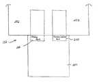
- FIG. 1Aillustrates a prior art configuration where a wireless modem 104 is inserted into a laptop computer 106 .
- the wireless modem 104allows the laptop computer 106 to communicate with a communication device (not shown).
- the wireless modem 104communicates with the with the laptop computer 106 via a communication port (COM PORT) 108 .
- the communication port 108is configured such that the wireless modem 104 transmits data to the laptop computer 106 while the wireless modem 104 is on-line.
- the wireless modem 104loses contact with communication device.
- the wireless modem 104loses contact for many reasons, including an increased temperature of the wireless modem 104 which may cause the wireless modem 104 to shut down.
- the wireless modem 104may also lose contact due to a weak signal strength with the communication device or a complete loss of signal.
- the communication port 108if any of the aforementioned problems arise, the user is not informed as the wireless modem 104 is transmitting information since the wireless modem has only one way to contact the laptop computer 106 , the communication port 108 .
- the communication port 108is occupied with the data transmission while the wireless modem 104 is transmitting.
- the wireless modem 104has no other way to inform a user of the aforementioned problems. Therefore, if the modem loses contact with the communication device, the user is not informed of the loss of contact. Thus, the user will continue to transmit information with the wireless modem, once in fact the data sent is lost. In order for the user to determine whether or not contact is still maintained with the communication device, the user must go off-line in non-TCP/IP applications.
- FIG. 1Bshows another prior art wireless modem 110 which communicates with the laptop computer 106 .
- the wireless modem 110is transmitting data using a transmission control protocol/internet protocol (TCP/IP) application.
- TCP/IPtransmission control protocol/internet protocol
- the wireless modem 110has the ability to update a user of the status of the wireless modem 110 as the wireless modem 110 transmits data using TCP/IP.
- the wireless modem 110is updating the laptop computer 106 using the same communication port 108 .
- the wireless modem 110only when the wireless modem 110 is transmitting with TCP/IP can the wireless modem 110 update the user of the status of the wireless modem 110 during data transmission.
- this new communication deviceshould have the ability to simultaneously transmit data and update the user of status changes.
- the present inventionfills the aforementioned needs by providing a multifunction interface for a PC card.
- the multifunction interfaceprovides communication port and status port capabilities to the PC card.
- the communication portallows the PC card to transmit data to and from a host.
- the status portallows the PC card to provide real-time status information of the PC card to the host as the PC card transmits data to and from the host.
- a multi-function interfacefor interfacing a communication device with a host.
- the multi-function interfaceincludes a plurality of logical devices which are associated with the communication device.
- the plurality of logical devicesprovide connectivity between the communication device and the host.
- the plurality of logical devicesare configured such that the plurality of logical devices may simultaneously communicate with the host while the communication device is on-line.
- a communication devicewhich communicates with a host.
- the communication deviceincludes a plurality of logical devices associated with the communication device.
- the plurality of logical devicesprovide connectivity to the host with a communication port and a status port.
- the communication porttransmits data between the communication device and the host.
- the status portprovides real-time status information of the communication device to the host as the communication device is transmitting information using the communication port.
- a multi-function interfacewhich provides connectivity between a communication device and a computing device.
- the multi-function interfaceincludes a plurality of logical devices associated with the communication device.
- the plurality of logical devicesestablishes connectivity between the communication device and the computing device.
- the multi-function interfacecomprises a communication port and a status port.
- the communication portwhich is one of the plurality of logical devices, transmits data between the communication device and the computing device.
- the status portwhich is also one of the plurality of logical devices, provides real-time status information of the communication device as the communication port transmits data between the communication device and the computing device.
- a wireless communication devicewhich is in communication with a computing device.
- a plurality of logical devicesestablishes connectivity between the wireless communication device and the computing device.
- the wireless communication devicesincludes a communication port and a status port.
- the communication portwhich is a logical device of the plurality of logical devices, transmits data between the wireless communication device and the computing device.
- the status portwhich is another logical device of the plurality of logical devices, provides real-time status information of the wireless communication device to the computing device as the communication port transmits data between the wireless communication device and the computing device.
- the present inventionnow allows for a communication device to simultaneously transmit data and update a user with status information of the communication device as the communication device is transmitting the data.
- the useris updated with real-time status information of the communication device as the communication device is transmitting data.
- FIG. 1Aillustrates a schematic of a prior art configuration of a wireless modem where the wireless modem is inserted into a laptop computer.
- FIG. 1Bshows another schematic of a prior art configuration where a wireless modem communicates with the laptop computer.
- FIG. 2illustrates a schematic of a host transmitting data, as denoted with bi-directional arrow “A”, to a network in accordance with one embodiment of the present invention.
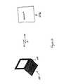
- FIG. 3shows a schematic of a multi-function interface which interfaces a PC card with the host shown with respect to FIG. 2 using a status port and a communication port, in accordance with one embodiment of the present invention.
- the present inventiondiscloses a multi-function interface which includes a plurality of logical devices that are associated with the communication device.
- the multi-function interface of the present inventionallows for a PC card to simultaneously transmit data to a host and provide status information of the PC card while the PC card is on-line.
- the PC cardtransmits data and provides status information using two logical devices associated with the PC card.
- FIG. 2illustrates a schematic of a host 202 transmitting data, as denoted with bi-directional arrow “A”, to a network 206 , in accordance with one embodiment of the present invention.
- the host 202may be any computing device which contains a processor and memory.
- the network 206may be any device or system which is a major communication carrier which facilitates communication with hosts connected to the major carrier.
- the host 202uses the PC card 204 to wirelessly communicate with the network 206 , as denoted with bi-directional arrow “A.”
- the PC card 204may be any type of card which allows for wireless communication between the host 202 and the network 206 , such as a wireless modem.
- the PC card 204is an AirCardTM 510 available from Sierra Wireless located in Richmond, British Columbia, Canada. As the PC card 204 transmits data between the network 206 and the host 202 , the PC card 204 provides status information of the PC card 204 to the host 202 , as shown with reference to FIG. 3 .
- FIG. 3shows a schematic of a multi-function interface 212 which interfaces the PC card 204 with the host 202 shown with respect to FIG. 2 , using a status port 208 and a communication port 210 , in accordance with one embodiment of the present invention.
- the PC card 204communicates with the host 202
- the PC card 204implements two logical devices, the status port 208 and the communication port 210 of the multi-function interface 212 .
- a field programmable gate array (FPGA)configures the status port 208 and the communication port 210 on the PC card 204 .
- the PC card 204is a personal computer memory card international association (PCMCIA) card having multi-functional capabilities.
- PCMCIApersonal computer memory card international association
- the operating system of the host 202is notified that the PC card 204 is a multi-functional device having two logical devices associated with the PC card 204 . It should be noted that in another embodiment of the present invention, the PC card 204 and the associated logical devices are extendable to both internal and external modems for other bus technologies that support multi-function technology, such as universal serial bus (USB), CardBus or the like.
- USBuniversal serial bus
- CardBusor the like.
- the status port 208 and the communication port 210form the multi-function interface 212 which allow the PC card 204 to interface with the host 202 .
- the status port 208 and the communication port 210are two logical devices associated with the PC card 204 .
- the status port 208 and the communication port 210appear as two separate peripheral devices to the host 202 .
- the status port 208provides real-time status information to the host 202 while the PC card 204 and the host 202 are on-line using the communication port 210 .
- the status information provided to the host 202updates a user of various data (i.e., temperature of the PC card 204 , signal strength of the PC card 204 , etc.) as the PC card 204 transmits data with the host 202 to a second communication device (not shown).
- various datai.e., temperature of the PC card 204 , signal strength of the PC card 204 , etc.
- the communication port 210transmits data to and from the host 202 using various applications in one embodiment of the present invention. These applications include both internet protocol (IP) applications such as electronic mail and non-IP applications such as facsimile transmissions and dial-up applications.
- IPinternet protocol
- the communication port 210 and the status port 208are two logical devices associated with the PC card 204 .
- the status port 208simultaneously provides status information of the PC card 204 to the host 202 as the PC card 204 is transmitting data. Therefore, a user transmitting data with the PC card 204 is continually updated of the status of the PC card 204 as the PC card 204 is transmitting data to the network 206 (shown with reference to FIG. 2 ).
- the status port 208 and the communication port 210are not two independent functions. Instead, the status port 208 and the communication port 210 are peripheral devices for the same function, the PC card 204 , which, in one embodiment, is a wireless communication device.
- the present inventionnow allows a user to monitor the status of a wireless modem as the wireless modem transmits data.
- a user transmitting data with the wireless modem of the present inventionincludes the ability to monitor important status information of the wireless modem while data is transmitted.
- this informationincludes frame error rate, the received signal strength of the wireless modem and roaming indication.
- the status portmay be used to set and write various parameters, such as a system identification (SID) and a network identification (NID).
- SIDsystem identification
- NIDnetwork identification
- the usercan then determine when data transmission should stop to minimize the possibility of losing information prior to loss of the signal.
- An example of thisis a user transmitting data in a moving vehicle. If coverage (i.e., cell-site coverage) begins to diminish as the user moves further away from a cell-site, the user is informed of the weakening signal. Thus, a user is notified beforehand of the possibility of signal loss, thereby allowing the user the opportunity to plan for the signal loss. Also, the user is notified if the wireless modem does not have a signal. As such, the user will not transmit data when the wireless modem has lost the signal. Again, the possibility of losing information is avoided.
- coveragei.e., cell-site coverage
- Another advantage of the present inventionincludes the ability to extend the present invention to other bus technologies, thereby increasing the functionality of the present invention.
- the present inventionmay use other bus technologies which support multifunction technologies. As such, the present invention may utilize other technologies as they become available.
- the wireless modemuses code division multiple access (CDMA) technology.
- CDMAcode division multiple access
- the present inventionis not limited to TCP/IP based applications.
- the present inventionmay implement all IP-based and all non-IP based applications, including electronic mail and facsimile transmissions.
Landscapes
- Engineering & Computer Science (AREA)
- Environmental & Geological Engineering (AREA)
- Computer Networks & Wireless Communication (AREA)
- Signal Processing (AREA)
- Telephonic Communication Services (AREA)
- Communication Control (AREA)
- Facsimiles In General (AREA)
Abstract
Description
1. Field of the Invention
The present invention relates generally to wireless communications with a network, and more specifically the present invention relates to a multi-function interface which allows a wireless modem which provides real-time updating while on-line.
2. Description of Related Art
Today, users reliance on wireless communication continues to steadily increase. This reliance includes the use of wireless communication with laptop computers. These laptop computers have the ability to send and receive data, such as files and other attachments, using wireless PC cards such as wireless modems.
Typically, these wireless modems are in the form of PC cards and similar peripheral devices which are inserted into a laptop computer. When the wireless modem is inserted into the laptop computer, the wireless modem has one port which connects to the laptop computer. To further illustrate, reference is now made toFIG. 1A , which illustrates a prior art configuration where awireless modem 104 is inserted into alaptop computer 106. Thewireless modem 104 allows thelaptop computer 106 to communicate with a communication device (not shown). When thewireless modem 104 is inserted into thelaptop computer 106, thewireless modem 104 communicates with the with thelaptop computer 106 via a communication port (COM PORT)108. Thecommunication port 108 is configured such that thewireless modem 104 transmits data to thelaptop computer 106 while thewireless modem 104 is on-line.
However, as thewireless modem 104 is on-line and transmitting information to a communication device from the laptop computer, thewireless modem 104 loses contact with communication device. Thewireless modem 104 loses contact for many reasons, including an increased temperature of thewireless modem 104 which may cause thewireless modem 104 to shut down. Thewireless modem 104 may also lose contact due to a weak signal strength with the communication device or a complete loss of signal. However, if any of the aforementioned problems arise, the user is not informed as thewireless modem 104 is transmitting information since the wireless modem has only one way to contact thelaptop computer 106, thecommunication port 108. Thecommunication port 108 is occupied with the data transmission while thewireless modem 104 is transmitting. As a result, thewireless modem 104 has no other way to inform a user of the aforementioned problems. Therefore, if the modem loses contact with the communication device, the user is not informed of the loss of contact. Thus, the user will continue to transmit information with the wireless modem, once in fact the data sent is lost. In order for the user to determine whether or not contact is still maintained with the communication device, the user must go off-line in non-TCP/IP applications.
Now making reference toFIG. 1B ,FIG. 1B shows another prior artwireless modem 110 which communicates with thelaptop computer 106. In the configuration shown with respect toFIG. 1B , thewireless modem 110 is transmitting data using a transmission control protocol/internet protocol (TCP/IP) application. In this configuration, thewireless modem 110 has the ability to update a user of the status of thewireless modem 110 as thewireless modem 110 transmits data using TCP/IP. However, thewireless modem 110 is updating thelaptop computer 106 using thesame communication port 108. In addition, only when thewireless modem 110 is transmitting with TCP/IP can thewireless modem 110 update the user of the status of thewireless modem 110 during data transmission. As those skilled in the art will appreciate, when a user is transmitting non-TCP/IP applications, such as faxing or dialup applications, the user is not updated of the status of the wireless modem. As such, if the user is faxing data to another communication device and the signal is lost (i.e., user is outside of cell site coverage), a portion of the facsimile is lost.
Therefore, a need exists for a communication device which updates a user of status changes of the communication device during data transmission. Furthermore, this new communication device should have the ability to simultaneously transmit data and update the user of status changes.
The present invention fills the aforementioned needs by providing a multifunction interface for a PC card. The multifunction interface provides communication port and status port capabilities to the PC card. The communication port allows the PC card to transmit data to and from a host. The status port allows the PC card to provide real-time status information of the PC card to the host as the PC card transmits data to and from the host.
In one embodiment of the present invention, a multi-function interface for interfacing a communication device with a host is disclosed. The multi-function interface includes a plurality of logical devices which are associated with the communication device. The plurality of logical devices provide connectivity between the communication device and the host. The plurality of logical devices are configured such that the plurality of logical devices may simultaneously communicate with the host while the communication device is on-line.
In a further embodiment of the present invention, a communication device which communicates with a host is disclosed. The communication device includes a plurality of logical devices associated with the communication device. The plurality of logical devices provide connectivity to the host with a communication port and a status port. The communication port transmits data between the communication device and the host. The status port provides real-time status information of the communication device to the host as the communication device is transmitting information using the communication port.
In yet another embodiment of the present invention, a multi-function interface which provides connectivity between a communication device and a computing device is disclosed. The multi-function interface includes a plurality of logical devices associated with the communication device. The plurality of logical devices establishes connectivity between the communication device and the computing device. The multi-function interface comprises a communication port and a status port. The communication port, which is one of the plurality of logical devices, transmits data between the communication device and the computing device. The status port, which is also one of the plurality of logical devices, provides real-time status information of the communication device as the communication port transmits data between the communication device and the computing device.
In another embodiment of the present invention, a wireless communication device which is in communication with a computing device is disclosed. A plurality of logical devices establishes connectivity between the wireless communication device and the computing device. The wireless communication devices includes a communication port and a status port. The communication port, which is a logical device of the plurality of logical devices, transmits data between the wireless communication device and the computing device. The status port, which is another logical device of the plurality of logical devices, provides real-time status information of the wireless communication device to the computing device as the communication port transmits data between the wireless communication device and the computing device.
As may be appreciated, the present invention now allows for a communication device to simultaneously transmit data and update a user with status information of the communication device as the communication device is transmitting the data. Thus, the user is updated with real-time status information of the communication device as the communication device is transmitting data.
Many advantages of the present invention will be apparent to those skilled in the art with a reading of this specification in conjunction with the attached drawings, wherein like reference numerals are applied to like elements and wherein:
The present invention discloses a multi-function interface which includes a plurality of logical devices that are associated with the communication device. As an overview, the multi-function interface of the present invention allows for a PC card to simultaneously transmit data to a host and provide status information of the PC card while the PC card is on-line. As will be more fully discussed with reference to the accompanying Figures, the PC card transmits data and provides status information using two logical devices associated with the PC card.
Now making reference to the Figures, and more particularly toFIG. 2 ,FIG. 2 illustrates a schematic of ahost 202 transmitting data, as denoted with bi-directional arrow “A”, to a network206, in accordance with one embodiment of the present invention. Thehost 202 may be any computing device which contains a processor and memory. The network206 may be any device or system which is a major communication carrier which facilitates communication with hosts connected to the major carrier. Thehost 202 uses thePC card 204 to wirelessly communicate with the network206, as denoted with bi-directional arrow “A.” ThePC card 204 may be any type of card which allows for wireless communication between thehost 202 and the network206, such as a wireless modem. In one embodiment of the present invention, thePC card 204 is an AirCard™510 available from Sierra Wireless located in Richmond, British Columbia, Canada. As thePC card 204 transmits data between the network206 and thehost 202, thePC card 204 provides status information of thePC card 204 to thehost 202, as shown with reference to FIG.3.
As discussed earlier, thestatus port 208 and thecommunication port 210 form themulti-function interface 212 which allow thePC card 204 to interface with thehost 202. Thestatus port 208 and thecommunication port 210 are two logical devices associated with thePC card 204. Thus, thestatus port 208 and thecommunication port 210 appear as two separate peripheral devices to thehost 202. Thestatus port 208 provides real-time status information to thehost 202 while thePC card 204 and thehost 202 are on-line using thecommunication port 210. The status information provided to thehost 202 updates a user of various data (i.e., temperature of thePC card 204, signal strength of thePC card 204, etc.) as thePC card 204 transmits data with thehost 202 to a second communication device (not shown).
Thecommunication port 210 transmits data to and from thehost 202 using various applications in one embodiment of the present invention. These applications include both internet protocol (IP) applications such as electronic mail and non-IP applications such as facsimile transmissions and dial-up applications. As stated earlier, thecommunication port 210 and thestatus port 208 are two logical devices associated with thePC card 204. Thus, as thecommunication port 210 transmits data to and from thehost 202, thestatus port 208 simultaneously provides status information of thePC card 204 to thehost 202 as thePC card 204 is transmitting data. Therefore, a user transmitting data with thePC card 204 is continually updated of the status of thePC card 204 as thePC card 204 is transmitting data to the network206 (shown with reference to FIG.2). It should be noted that thestatus port 208 and thecommunication port 210 are not two independent functions. Instead, thestatus port 208 and thecommunication port 210 are peripheral devices for the same function, thePC card 204, which, in one embodiment, is a wireless communication device.
As may be appreciated, the present invention now allows a user to monitor the status of a wireless modem as the wireless modem transmits data. There are many advantages to a user transmitting data with the wireless modem of the present invention. These advantages include the ability to monitor important status information of the wireless modem while data is transmitted. In one embodiment, this information includes frame error rate, the received signal strength of the wireless modem and roaming indication. In addition, as the wireless modem is on-line, the status port may be used to set and write various parameters, such as a system identification (SID) and a network identification (NID). The use of a status port and a communication port allows the user to monitor the signal strength of the wireless modem while transmitting. The user can then determine when data transmission should stop to minimize the possibility of losing information prior to loss of the signal. An example of this is a user transmitting data in a moving vehicle. If coverage (i.e., cell-site coverage) begins to diminish as the user moves further away from a cell-site, the user is informed of the weakening signal. Thus, a user is notified beforehand of the possibility of signal loss, thereby allowing the user the opportunity to plan for the signal loss. Also, the user is notified if the wireless modem does not have a signal. As such, the user will not transmit data when the wireless modem has lost the signal. Again, the possibility of losing information is avoided.
Another advantage of the present invention includes the ability to extend the present invention to other bus technologies, thereby increasing the functionality of the present invention. The present invention may use other bus technologies which support multifunction technologies. As such, the present invention may utilize other technologies as they become available.
Furthermore, in one embodiment, the wireless modem uses code division multiple access (CDMA) technology. The present invention is not limited to TCP/IP based applications. Thus, the present invention may implement all IP-based and all non-IP based applications, including electronic mail and facsimile transmissions.
The above are exemplary modes of carrying out the invention and are not intended to be limiting. It will be apparent to those of ordinary skill in the art that modifications thereto can be made without departure from the spirit and scope of the invention as set forth in the following claims.
Claims (41)
1. A multi-function interface for interfacing a wireless modem with a host, the multi-function interface including a plurality of logical devices associated with the wireless modem such that the plurality of logical devices provide connectivity between the wireless modem and the host, wherein the plurality of logical devices includes a first logical device for providing both Internet Protocol (IP)-based and non-IP-based communication capabilities between the wireless modem and the host, and the plurality of logical devices includes a second logical device for providing real-time status information of the wireless modem to the host during operation.
2. A multi-function interface as recited inclaim 1 , wherein the first logical device is a communication port.
3. A multi-function interface as recited inclaim 2 , wherein the second logical device is a status port.
4. A multi-function interface as recited inclaim 3 , wherein the status port provides the real-time status information as the wireless modem is on-line.
5. A multi-function interface as recited inclaim 1 , wherein the wireless modem is a personal communication memory card international association (PCMCIA) card.
6. A multi-function interface as recited inclaim 1 , wherein the plurality of logical devices are configured using a field programmable gate array (FPGA) such that two communication port capabilities are provided.
7. A wireless modem which communicates with a host, the wireless modem including a plurality of logical devices associated with the wireless modem, where the plurality of logical devices provide connectivity to the host, and where at least one of the logical device accommodate both Internet Protocol (IP)-based and non-IP-based communications between the wireless modem and the host.
8. A wireless modem as recited inclaim 7 , wherein the plurality of logical devices includes a first logical device associated with the wireless modem.
9. A wireless modem as recited inclaim 8 , wherein the first logical device provides a status port between the wireless modem and the host.
10. A wireless modem as recited inclaim 9 , wherein the status port allows the wireless modem to provide real-time status information of the wireless modem to the host.
11. A wireless modem as recited inclaim 10 , wherein the real-time status information of the wireless modem includes the signal strength of radio frequency signals being received by the wireless modem.
12. A wireless modem as recited inclaim 10 , wherein the real-time status information of the wireless modem includes the temperature of the wireless modem as the wireless modem communicates with other communication devices.
13. A wireless modem as recited inclaim 8 , wherein the plurality of logical devices includes a second logical device associated with the wireless modem.
14. A wireless modem as recited inclaim 13 , wherein the second logical device provides a communication port between the wireless modem and the host.
15. A wireless modem as recited inclaim 14 , wherein the communication port allows the wireless modem to transmit data from the host to another communication device.
16. A wireless modem as recited inclaim 13 , wherein the first logical device and the second logical device communicate simultaneously with the host.
17. A wireless modem as recited inclaim 13 , wherein the second logical device transmits IP based and non-IP based applications.
18. A multi-function interface which provides connectivity between a wireless communication device and a computing device, where connectivity is established using a plurality of logical devices associated with the wireless communication device, the multi-function interface comprising:
a communication port, the communication port being one of the plurality of logical devices, the communication port transmitting both Internet Protocol (IP)-based and non-IP-based data between the wireless communication device and the computing device; and
a status port, the status port being one of the plurality of logical devices, the status port providing real-time status information of the wireless communication devise when the communication port transmits data.
19. A multi-function interface as recited inclaim 18 , wherein the communication port is configured using a field programmable gate array (FPGA).
20. A multi-function interface as recited inclaim 18 , wherein the status port is configured using a field programmable gate array (FPGA).
21. A multi-function interface as recited inclaim 18 , wherein the communication port and the status port communicate with the host simultaneously.
22. A multi-function interface as recited inclaim 18 , wherein the wireless communication device is a wireless modem.
23. A multi-function interface as interface as recited inclaim 22 , wherein the real-time status information includes a signal strength of radio frequency signals being received by the wireless modem as the data is transmitted between the wireless modem and the host.
24. A multi-function interface as recited inclaim 22 , wherein the real-time status information includes informing the host if the wireless modem is maintaining a signal with a network during data transmission.
25. A wireless communication device in communication with a computing device, where connectivity between the wireless communication device and the computing device is established with a plurality of logical devices, the wireless communication device comprising:
a communication port, the communication port being a logical device of the plurality of logical devices, where the communication port is capable of transmitting both Internet Protocol (IP)-based and non-IP-based data between the wireless communication device and the computing device; and
a status port, the status port being another logical device of the plurality of logical devices, where the status port provides real-time status information to the computing device as the communication port transmits data between the wireless communication device and the computing device.
26. A wireless communication device as recited inclaim 25 , wherein the wireless communication device is a personal computer memory card international association (PCMCIA) card.
27. A wireless communication device as recited inclaim 25 , wherein the wireless communication device is a wireless modem.
28. A wireless communication device as recited inclaim 25 , wherein the real-time status information includes a temperature of the wireless modem.
29. A wireless communication device as recited inclaim 25 , wherein the real-time status information includes a signal strength of radio frequency signals being received by the wireless modem as the wireless modem transmits the data.
30. A wireless communication device as recited inclaim 25 , wherein the communication port and the status port simultaneously communicate with the host.
31. A wireless communication device as recited inclaim 25 , wherein a field programmable gate array (FPGA) is used to configure the communication port.
32. A wireless communication device as recited inclaim 25 , wherein a field programmable gate array (FPGA) is used to configure the status port.
33. A multi-function interface for providing connectivity between a wireless network interface card (NIC) and a host computer, comprising:
a communication port configured to transmit either Internet Protocol (IP)-based or non-IP-based data between the wireless NIC and the host computer; and
a status port configured to provide status information to the host computer while the wireless NIC is transmitting data to a remote device.
34. The multi-function interface ofclaim 33 wherein the status port is further configured to provide status information to the host computer while the host computer communicates with the wireless NIC.
35. The multi-function interface ofclaim 33 wherein the status port is further configured to provide status information to the host computer while the wireless NIC is receiving data from the remote device.
36. The multi-function interface ofclaim 33 wherein the status port is further configured to provide status information to the host during a time when there is no wireless network connection between the wireless NIC and the remote device.
37. The multi-function interface ofclaim 36 wherein the status information comprises a connection status of the wireless network connection.
38. The multi-function interface ofclaim 36 wherein the status information comprises an operational condition of the wireless NIC.
39. The multi-function interface ofclaim 33 wherein the status information comprises a connection status of the wireless network connection between the remote device and the wireless NIC.
40. The multi-function interface ofclaim 39 wherein said status of the wireless network connection includes an indication of signal strength.
41. The multi-function interface ofclaim 33 wherein the status information comprises an operational condition of the wireless NIC.
Priority Applications (13)
| Application Number | Priority Date | Filing Date | Title |
|---|---|---|---|
| US09/764,164US6886049B2 (en) | 2001-01-16 | 2001-01-16 | Multi-function interface for connectivity between a communication device and a host |
| CNA2008101612777ACN101383762A (en) | 2001-01-16 | 2002-01-02 | Multifunctional interface for connection between communication device and host computer |
| AT02715331TATE331386T1 (en) | 2001-01-16 | 2002-01-02 | MULTI-FUNCTION INTERFACE FOR CONNECTING A COMMUNICATIONS DEVICE TO A HOST |
| ES02715331TES2266469T3 (en) | 2001-01-16 | 2002-01-02 | MULTIFUNCTION INTERFACE FOR CONNECTIVITY BETWEEN A COMMUNICATION DEVICE AND A CENTRAL NETWORK COMPUTER. |
| DE60232031TDE60232031D1 (en) | 2001-01-16 | 2002-01-02 | Multi-function interface for connecting a communication device to a host |
| PCT/CA2002/000007WO2002057929A2 (en) | 2001-01-16 | 2002-01-02 | Multi-function interface for connectivity between a communication device and a host |
| CNA028038010ACN1486567A (en) | 2001-01-16 | 2002-01-02 | Multifunctional interface for connection between a communication device and a host |
| EP02715331AEP1352512B1 (en) | 2001-01-16 | 2002-01-02 | Multi-function interface for connectivity between a communication device and a host |
| ES06115737TES2326001T3 (en) | 2001-01-16 | 2002-01-02 | MULTIFUNCTION INTERFACE FOR CONNECTIVITY BETWEEN A COMMUNICATION DEVICE AND AN HOST. |
| EP06115737AEP1699221B1 (en) | 2001-01-16 | 2002-01-02 | Multi-function interface for connectivity between a communication device and a host |
| DE60212569TDE60212569T2 (en) | 2001-01-16 | 2002-01-02 | MULTI FUNCTION INTERFACE FOR CONNECTING A COMMUNICATION DEVICE TO A HOST |
| AT06115737TATE429125T1 (en) | 2001-01-16 | 2002-01-02 | MULTI-FUNCTION INTERFACE FOR CONNECTING A COMMUNICATIONS DEVICE TO A HOST |
| HK07102441.4AHK1095232B (en) | 2001-01-16 | 2007-03-05 | Multi-function interface for connectivity between a communication device and a host |
Applications Claiming Priority (1)
| Application Number | Priority Date | Filing Date | Title |
|---|---|---|---|
| US09/764,164US6886049B2 (en) | 2001-01-16 | 2001-01-16 | Multi-function interface for connectivity between a communication device and a host |
Publications (2)
| Publication Number | Publication Date |
|---|---|
| US20020095530A1 US20020095530A1 (en) | 2002-07-18 |
| US6886049B2true US6886049B2 (en) | 2005-04-26 |
Family
ID=25069860
Family Applications (1)
| Application Number | Title | Priority Date | Filing Date |
|---|---|---|---|
| US09/764,164Expired - LifetimeUS6886049B2 (en) | 2001-01-16 | 2001-01-16 | Multi-function interface for connectivity between a communication device and a host |
Country Status (7)
| Country | Link |
|---|---|
| US (1) | US6886049B2 (en) |
| EP (2) | EP1352512B1 (en) |
| CN (2) | CN1486567A (en) |
| AT (2) | ATE429125T1 (en) |
| DE (2) | DE60212569T2 (en) |
| ES (2) | ES2266469T3 (en) |
| WO (1) | WO2002057929A2 (en) |
Cited By (7)
| Publication number | Priority date | Publication date | Assignee | Title |
|---|---|---|---|---|
| US20040203467A1 (en)* | 2003-01-21 | 2004-10-14 | Liu Jerry J. | System and method for testing portable communication devices |
| US20070223599A1 (en)* | 2005-07-25 | 2007-09-27 | Sysair, Inc., A Delaware Corporation | Cellular PC modem architecture and method of operation |
| US20090158301A1 (en)* | 2007-12-14 | 2009-06-18 | Microsoft Corporation | Multi-function device ID with unique identifier |
| US20090293070A1 (en)* | 2008-05-22 | 2009-11-26 | Microsoft Corporation | Device display object infrastructure |
| US20110302340A1 (en)* | 2010-06-04 | 2011-12-08 | Samsung Electronics Co., Ltd. | System and method detecting cable plug status in display device |
| US8750320B2 (en) | 1997-01-23 | 2014-06-10 | Broadcom Corporation | Fibre channel arbitrated loop bufferless switch circuitry to increase bandwidth without significant increase in cost |
| US8798091B2 (en) | 1998-11-19 | 2014-08-05 | Broadcom Corporation | Fibre channel arbitrated loop bufferless switch circuitry to increase bandwidth without significant increase in cost |
Families Citing this family (4)
| Publication number | Priority date | Publication date | Assignee | Title |
|---|---|---|---|---|
| JP2003174521A (en)* | 2001-12-07 | 2003-06-20 | Ntt Docomo Inc | Communication module execution control system, communication module execution control method, application execution control system, and application execution control method |
| US20050015644A1 (en)* | 2003-06-30 | 2005-01-20 | Microsoft Corporation | Network connection agents and troubleshooters |
| KR100801649B1 (en)* | 2006-10-12 | 2008-02-05 | 삼성전자주식회사 | Standby power saving method of mobile terminal |
| CN112600738B (en)* | 2020-12-18 | 2022-04-08 | 中国农业银行股份有限公司 | Method and device for verifying connectivity of network port |
Citations (11)
| Publication number | Priority date | Publication date | Assignee | Title |
|---|---|---|---|---|
| US4799153A (en)* | 1984-12-14 | 1989-01-17 | Telenet Communications Corporation | Method and apparatus for enhancing security of communications in a packet-switched data communications system |
| EP0628908A1 (en) | 1993-05-20 | 1994-12-14 | AT&T Corp. | PCMCIA interface using shared memory |
| US5535242A (en) | 1992-03-30 | 1996-07-09 | International Business Machines Corporation | Method and system for modem command processing during data transfer |
| US5748878A (en)* | 1995-09-11 | 1998-05-05 | Applied Microsystems, Inc. | Method and apparatus for analyzing software executed in embedded systems |
| US5752077A (en)* | 1995-05-15 | 1998-05-12 | Motorola, Inc. | Data processing system having a multi-function input/output port with individual pull-up and pull-down control |
| US5784633A (en)* | 1996-03-12 | 1998-07-21 | International Business Machines Corporation | System for obtaining status data unrelated to user data path from a modem and providing control data to the modem without interrupting user data flow |
| US5790958A (en)* | 1995-10-16 | 1998-08-04 | Mmgt Enterprises, Inc. | Radio reception system for general purpose computer |
| US6067317A (en) | 1996-05-17 | 2000-05-23 | Lucent Technologies Inc. | Computer bus resource port |
| US6360281B1 (en)* | 1998-05-29 | 2002-03-19 | 3Com Corporation | System and method for communicating with a serial communications device using multiple virtual ports |
| US6389486B1 (en)* | 1999-05-06 | 2002-05-14 | Ericsson Inc. | Systems and methods for transferring PCMCIA card status information to host devices |
| US6463469B1 (en)* | 2000-01-18 | 2002-10-08 | Edward Q. Yavitz | Computer-based RDS/MBS receiver system for use with radio broadcast signal |
- 2001
- 2001-01-16USUS09/764,164patent/US6886049B2/ennot_activeExpired - Lifetime
- 2002
- 2002-01-02CNCNA028038010Apatent/CN1486567A/enactivePending
- 2002-01-02EPEP02715331Apatent/EP1352512B1/ennot_activeExpired - Lifetime
- 2002-01-02ATAT06115737Tpatent/ATE429125T1/ennot_activeIP Right Cessation
- 2002-01-02DEDE60212569Tpatent/DE60212569T2/ennot_activeExpired - Lifetime
- 2002-01-02WOPCT/CA2002/000007patent/WO2002057929A2/enactiveIP Right Grant
- 2002-01-02ESES02715331Tpatent/ES2266469T3/ennot_activeExpired - Lifetime
- 2002-01-02DEDE60232031Tpatent/DE60232031D1/ennot_activeExpired - Lifetime
- 2002-01-02ATAT02715331Tpatent/ATE331386T1/ennot_activeIP Right Cessation
- 2002-01-02ESES06115737Tpatent/ES2326001T3/ennot_activeExpired - Lifetime
- 2002-01-02CNCNA2008101612777Apatent/CN101383762A/enactivePending
- 2002-01-02EPEP06115737Apatent/EP1699221B1/ennot_activeExpired - Lifetime
Patent Citations (11)
| Publication number | Priority date | Publication date | Assignee | Title |
|---|---|---|---|---|
| US4799153A (en)* | 1984-12-14 | 1989-01-17 | Telenet Communications Corporation | Method and apparatus for enhancing security of communications in a packet-switched data communications system |
| US5535242A (en) | 1992-03-30 | 1996-07-09 | International Business Machines Corporation | Method and system for modem command processing during data transfer |
| EP0628908A1 (en) | 1993-05-20 | 1994-12-14 | AT&T Corp. | PCMCIA interface using shared memory |
| US5752077A (en)* | 1995-05-15 | 1998-05-12 | Motorola, Inc. | Data processing system having a multi-function input/output port with individual pull-up and pull-down control |
| US5748878A (en)* | 1995-09-11 | 1998-05-05 | Applied Microsystems, Inc. | Method and apparatus for analyzing software executed in embedded systems |
| US5790958A (en)* | 1995-10-16 | 1998-08-04 | Mmgt Enterprises, Inc. | Radio reception system for general purpose computer |
| US5784633A (en)* | 1996-03-12 | 1998-07-21 | International Business Machines Corporation | System for obtaining status data unrelated to user data path from a modem and providing control data to the modem without interrupting user data flow |
| US6067317A (en) | 1996-05-17 | 2000-05-23 | Lucent Technologies Inc. | Computer bus resource port |
| US6360281B1 (en)* | 1998-05-29 | 2002-03-19 | 3Com Corporation | System and method for communicating with a serial communications device using multiple virtual ports |
| US6389486B1 (en)* | 1999-05-06 | 2002-05-14 | Ericsson Inc. | Systems and methods for transferring PCMCIA card status information to host devices |
| US6463469B1 (en)* | 2000-01-18 | 2002-10-08 | Edward Q. Yavitz | Computer-based RDS/MBS receiver system for use with radio broadcast signal |
Cited By (13)
| Publication number | Priority date | Publication date | Assignee | Title |
|---|---|---|---|---|
| US8750320B2 (en) | 1997-01-23 | 2014-06-10 | Broadcom Corporation | Fibre channel arbitrated loop bufferless switch circuitry to increase bandwidth without significant increase in cost |
| US8774199B2 (en) | 1997-01-23 | 2014-07-08 | Broadcom Corporation | Fibre channel arbitrated loop bufferless switch circuitry to increase bandwidth without significant increase in cost |
| US8767756B2 (en) | 1997-01-23 | 2014-07-01 | Broadcom Corporation | Fibre channel arbitrated loop bufferless switch circuitry to increase bandwidth without significant increase in cost |
| US8798091B2 (en) | 1998-11-19 | 2014-08-05 | Broadcom Corporation | Fibre channel arbitrated loop bufferless switch circuitry to increase bandwidth without significant increase in cost |
| US7321766B2 (en)* | 2003-01-21 | 2008-01-22 | Agilent Technologies, Inc | System and method for testing portable communication devices |
| US20040203467A1 (en)* | 2003-01-21 | 2004-10-14 | Liu Jerry J. | System and method for testing portable communication devices |
| US20070223599A1 (en)* | 2005-07-25 | 2007-09-27 | Sysair, Inc., A Delaware Corporation | Cellular PC modem architecture and method of operation |
| US20090158301A1 (en)* | 2007-12-14 | 2009-06-18 | Microsoft Corporation | Multi-function device ID with unique identifier |
| US8365201B2 (en) | 2007-12-14 | 2013-01-29 | Microsoft Corporation | Multi-function device ID with unique identifier |
| US8347319B2 (en) | 2008-05-22 | 2013-01-01 | Microsoft Corporation | Device display object infrastructure |
| US20090293070A1 (en)* | 2008-05-22 | 2009-11-26 | Microsoft Corporation | Device display object infrastructure |
| US8347000B2 (en)* | 2010-06-04 | 2013-01-01 | Samsung Electronics Co., Ltd. | System and method detecting cable plug status in display device |
| US20110302340A1 (en)* | 2010-06-04 | 2011-12-08 | Samsung Electronics Co., Ltd. | System and method detecting cable plug status in display device |
Also Published As
| Publication number | Publication date |
|---|---|
| DE60232031D1 (en) | 2009-05-28 |
| US20020095530A1 (en) | 2002-07-18 |
| EP1699221A1 (en) | 2006-09-06 |
| CN101383762A (en) | 2009-03-11 |
| ATE429125T1 (en) | 2009-05-15 |
| EP1352512A2 (en) | 2003-10-15 |
| CN1486567A (en) | 2004-03-31 |
| DE60212569D1 (en) | 2006-08-03 |
| ES2266469T3 (en) | 2007-03-01 |
| WO2002057929A2 (en) | 2002-07-25 |
| DE60212569T2 (en) | 2007-06-14 |
| WO2002057929A3 (en) | 2002-10-10 |
| HK1095232A1 (en) | 2007-04-27 |
| ES2326001T3 (en) | 2009-09-28 |
| ATE331386T1 (en) | 2006-07-15 |
| EP1699221B1 (en) | 2009-04-15 |
| EP1352512B1 (en) | 2006-06-21 |
Similar Documents
| Publication | Publication Date | Title |
|---|---|---|
| US6886049B2 (en) | Multi-function interface for connectivity between a communication device and a host | |
| US7024224B2 (en) | Detachable radio module | |
| US5343319A (en) | Apparatus for adapting an electrical communications port to an optical communications port | |
| EP2522080B1 (en) | Wireless adapter | |
| US6922548B1 (en) | Providing remote network driver interface specification services over a wireless radio-frequency medium | |
| US7020118B2 (en) | System and method for activation of a wireless module | |
| EP1202378A1 (en) | Retractable antenna with blocking system for personal computer card | |
| WO2007010150A3 (en) | Network equipment for transmitting software modules for controlling mobile terminals | |
| US20040203370A1 (en) | Wireless gateway node | |
| US7924767B2 (en) | Control and status protocol | |
| WO2015056581A1 (en) | Control device, control method, cable, electronic device and communication device | |
| KR20010048601A (en) | Home gateway system for connecting home network and access network each having diverse protocols and network interfacing method thereof | |
| US7433346B2 (en) | Card device for high-speed wireless data communication | |
| KR100538903B1 (en) | Network interface device | |
| US7016358B2 (en) | Interface device with network isolation | |
| EP1125368B1 (en) | Battery case for pcmcia card modem with antenna | |
| US6847819B1 (en) | Adaptive transport TCP/IP phone management | |
| HK1095232B (en) | Multi-function interface for connectivity between a communication device and a host | |
| US5864751A (en) | System for programming a radio receiver | |
| KR200188090Y1 (en) | Lan connect apparatus for usb port | |
| KR20020064611A (en) | Wireless modem for internet terminal | |
| Kim et al. | Design and implementation of tiny-WiMAX connection manager (t-WCM) for specific purposed devices | |
| KR100566226B1 (en) | How to download system code of network equipment using SNP | |
| JPH10112739A (en) | Modem | |
| KR100487620B1 (en) | Mobile phone which commmunicates in many directions having infrared module |
Legal Events
| Date | Code | Title | Description |
|---|---|---|---|
| AS | Assignment | Owner name:SIERRA WIRELESS, INC, CANADA Free format text:ASSIGNMENT OF ASSIGNORS INTEREST;ASSIGNOR:WONG, CARL P.L.;REEL/FRAME:011481/0184 Effective date:20010112 | |
| STCF | Information on status: patent grant | Free format text:PATENTED CASE | |
| FPAY | Fee payment | Year of fee payment:4 | |
| CC | Certificate of correction | ||
| FPAY | Fee payment | Year of fee payment:8 | |
| FPAY | Fee payment | Year of fee payment:12 | |
| AS | Assignment | Owner name:ROLLING WIRELESS (H.K.) LIMITED, CHINA Free format text:ASSIGNMENT OF ASSIGNORS INTEREST;ASSIGNOR:SIERRA WIRELESS, INC;REEL/FRAME:056626/0307 Effective date:20210607 | |
| AS | Assignment | Owner name:ROLLING WIRELESS S.A R.L., LUXEMBOURG Free format text:ASSIGNMENT OF ASSIGNORS INTEREST;ASSIGNOR:ROLLING WIRELESS (H.K.) LIMITED;REEL/FRAME:059140/0648 Effective date:20220301 |