US6885185B1 - Modular meter configuration and methodology - Google Patents
Modular meter configuration and methodologyDownload PDFInfo
- Publication number
- US6885185B1 US6885185B1US09/450,890US45089099AUS6885185B1US 6885185 B1US6885185 B1US 6885185B1US 45089099 AUS45089099 AUS 45089099AUS 6885185 B1US6885185 B1US 6885185B1
- Authority
- US
- United States
- Prior art keywords
- baseplate
- board
- meter
- electricity meter
- metrology
- Prior art date
- Legal status (The legal status is an assumption and is not a legal conclusion. Google has not performed a legal analysis and makes no representation as to the accuracy of the status listed.)
- Expired - Lifetime
Links
- 238000000034methodMethods0.000titleclaimsabstractdescription47
- 230000005611electricityEffects0.000claimsabstractdescription85
- 238000012360testing methodMethods0.000claimsabstractdescription8
- 230000005540biological transmissionEffects0.000claimsdescription18
- 230000013011matingEffects0.000claimsdescription15
- 230000003287optical effectEffects0.000claimsdescription9
- 238000003780insertionMethods0.000claimsdescription7
- 230000037431insertionEffects0.000claimsdescription7
- 230000003993interactionEffects0.000claimsdescription6
- 238000003466weldingMethods0.000claimsdescription5
- 230000005355Hall effectEffects0.000claims5
- 239000004020conductorSubstances0.000claims3
- 230000004323axial lengthEffects0.000claims2
- 244000198134Agave sisalanaSpecies0.000claims1
- 230000015572biosynthetic processEffects0.000claims1
- 230000002452interceptive effectEffects0.000claims1
- 230000006870functionEffects0.000abstractdescription48
- 238000005516engineering processMethods0.000abstractdescription17
- 238000013461designMethods0.000abstractdescription9
- 239000007787solidSubstances0.000abstractdescription5
- 238000004891communicationMethods0.000description9
- 238000004519manufacturing processMethods0.000description9
- 238000010586diagramMethods0.000description8
- 230000000712assemblyEffects0.000description6
- 238000000429assemblyMethods0.000description6
- 239000003990capacitorSubstances0.000description6
- 238000012986modificationMethods0.000description6
- 230000004048modificationEffects0.000description6
- 238000012544monitoring processMethods0.000description5
- 238000010276constructionMethods0.000description4
- 239000000463materialSubstances0.000description4
- 230000007246mechanismEffects0.000description4
- 229920003023plasticPolymers0.000description4
- 238000013459approachMethods0.000description3
- 238000009826distributionMethods0.000description3
- 239000003999initiatorSubstances0.000description3
- 238000005259measurementMethods0.000description3
- 230000009471actionEffects0.000description2
- 230000009286beneficial effectEffects0.000description2
- 230000001413cellular effectEffects0.000description2
- 230000004907fluxEffects0.000description2
- 238000009434installationMethods0.000description2
- 238000002955isolationMethods0.000description2
- 239000002184metalSubstances0.000description2
- 238000012552reviewMethods0.000description2
- 239000000523sampleSubstances0.000description2
- 238000012549trainingMethods0.000description2
- 238000004026adhesive bondingMethods0.000description1
- 230000008859changeEffects0.000description1
- 238000012937correctionMethods0.000description1
- 230000001186cumulative effectEffects0.000description1
- 230000001419dependent effectEffects0.000description1
- 230000001627detrimental effectEffects0.000description1
- 238000007599dischargingMethods0.000description1
- 230000000694effectsEffects0.000description1
- 230000002708enhancing effectEffects0.000description1
- 230000005294ferromagnetic effectEffects0.000description1
- 239000011521glassSubstances0.000description1
- 230000000977initiatory effectEffects0.000description1
- 238000002372labellingMethods0.000description1
- 238000007726management methodMethods0.000description1
- 239000000203mixtureSubstances0.000description1
- 230000002093peripheral effectEffects0.000description1
- 238000004382pottingMethods0.000description1
- 238000003825pressingMethods0.000description1
- 230000001681protective effectEffects0.000description1
- 230000009993protective functionEffects0.000description1
- 230000008054signal transmissionEffects0.000description1
- 238000006467substitution reactionMethods0.000description1
- XLYOFNOQVPJJNP-UHFFFAOYSA-NwaterSubstancesOXLYOFNOQVPJJNP-UHFFFAOYSA-N0.000description1
Images


Classifications
- G—PHYSICS
- G01—MEASURING; TESTING
- G01R—MEASURING ELECTRIC VARIABLES; MEASURING MAGNETIC VARIABLES
- G01R22/00—Arrangements for measuring time integral of electric power or current, e.g. electricity meters
- G01R22/06—Arrangements for measuring time integral of electric power or current, e.g. electricity meters by electronic methods
- G01R22/061—Details of electronic electricity meters
- G01R22/065—Details of electronic electricity meters related to mechanical aspects
- G—PHYSICS
- G01—MEASURING; TESTING
- G01R—MEASURING ELECTRIC VARIABLES; MEASURING MAGNETIC VARIABLES
- G01R22/00—Arrangements for measuring time integral of electric power or current, e.g. electricity meters
- G01R22/06—Arrangements for measuring time integral of electric power or current, e.g. electricity meters by electronic methods
- G01R22/061—Details of electronic electricity meters
- G01R22/066—Arrangements for avoiding or indicating fraudulent use
- G—PHYSICS
- G01—MEASURING; TESTING
- G01R—MEASURING ELECTRIC VARIABLES; MEASURING MAGNETIC VARIABLES
- G01R21/00—Arrangements for measuring electric power or power factor
- G01R21/08—Arrangements for measuring electric power or power factor by using galvanomagnetic-effect devices, e.g. Hall-effect devices
- G—PHYSICS
- G02—OPTICS
- G02B—OPTICAL ELEMENTS, SYSTEMS OR APPARATUS
- G02B27/00—Optical systems or apparatus not provided for by any of the groups G02B1/00 - G02B26/00, G02B30/00
- G02B27/09—Beam shaping, e.g. changing the cross-sectional area, not otherwise provided for
- G02B27/0938—Using specific optical elements
- G02B27/0994—Fibers, light pipes
Definitions
- the present inventiongenerally concerns improved configurations and corresponding methodologies for modular meters and related features, and more particularly concerns integrated production of electricity meters capable of assuming a wide variety of optional and alternative features in respective embodiments based on certain common, base features.
- the subject inventionconcerns both apparatuses and methodologies in such areas, including in some instances the use of practical computer software applications involving an algorithmic approach to producing a useful, concrete and tangible result, i.e., namely, specific basic and selected higher level metrology functions.
- the general object of metrologyi.e., the science of measurement
- the general object of metrologyis to monitor one or more selected physical phenomena to permit a record of the monitored event(s).
- Such basic purpose of metrologycan be applied to a variety of metering devices used in a number of contexts.
- One broad area of measurementrelates, for example, to utility meters.
- Such rolemay include the monitoring of the consumption of a variety of forms of energy or other commodities, for example, including electricity, water, gas, and oil.
- additional desired datamay include rate of electricity consumption, or date and time of consumption.
- Solid state devices provided on printed circuit boards, for example, utilizing programmable integrated circuit components,have provided effective tools for implementing many of the higher level monitoring functions desired in the electricity meter context.
- U.S. Pat. No. 5,495,238discloses a utility meter making use of a light pipe through the case so that a light source from outside of the meter case may be piped into the meter for interaction with a rotating disc, so that information may be derived from returning light picked up by a pair of light detectors also outside the case.
- Such '238 patentalso represents an example of rotating disc technology as part of the mechanism for monitoring kilowatt hour consumption.
- U.S. Pat. No. 4,881,070discloses a device included within the meter for reading dials and for producing output signals for transmitting such readings and others to a remote location.
- the disclosure of U.S. Pat. No. 4,803,484is also related to such subject matter.
- An arrangementis disclosed in U.S. Pat. No. 4,922,187 for providing a pulse initiator circuit attachable to a utility meter without breaking the meter seal.
- Another pulse initiator formis included in U.S. Pat. No. 3,943,498.
- U.S. Pat. No. 4,121,147discloses a form of an adaptor which may be used as a housing for the pulse-pickup electronics along with whatever other additional circuits may be needed for manipulating resulting pulse data for performance of functions to obtain desired features.
- U.S. Pat. No. 5,364,290shows various electricity meter features, including use of particular molded base features with pairs of current spades projecting through and anchored to such base.
- U.S. Pat. No. 4,783,623is a further example of meter technology.
- U.S. Pat. No. 5,089,771is an example of a watt-hour meter reading device with a rotating disc and multiple dial register mechanism.
- a laminated “figure 8” power meter core exampleis disclosed in U.S. Pat. No. 5,694,103.
- U.S. Pat. No. 4,742,296shows a further example of three legged or “figure 8” ferromagnetic meter cores. Additional background references on such area include U.S. Pat. Nos. 4,491,790; 5,027,059; 5,338,996 and 5,523,677.
- U.S. Pat. No. 4,509,128sets forth an example of solid state electrical power demand register apparatus and methodology.
- U.S. Pat. No. 5,469,049also discloses an example of solid state technology, including a self-diagnostic electronic metering device. Background references related to such subject matter include, for example, U.S. Pat. Nos. 3,964,020; 4,056,775; 4,697,182; 4,734,639; 4,771,185; 4,884,021; 4,977,515; 4,979,122 and 5,059,896.
- U.S. Pat. No. 4,783,623discloses an example of a rotating disc type meter and a corresponding device for use therewith for recording energy use.
- Additional exemplary background references in the area of electric metersgenerally include U.S. Pat. Nos. 5,170,051; 5,214,587; 5,442,281; 5,519,387; 5,590,179 and 5,789,672.
- the present inventionrecognizes and addresses various of the foregoing shortcomings, and others concerning metrology devices and methodologies.
- a principal object of this inventionis improved meter configurations and corresponding methodologies. More particularly, a main concern is improved electricity meter configurations and corresponding methodologies.
- Another general object of the present inventionis to provide a meter configuration which is at least partially modular.
- Yet another general object of the present inventionis to provide improved meter configurations and corresponding methodologies which advantageously permit use of separate printed circuit boards, one for standard or basic features and another for customized, more advanced functions.
- itis a more particular object to permit customization of the higher level of functionality (or “personality”) of meter configurations in accordance with the invention.
- Such advantagesfurther result in improved delivery of manufactured devices to utility company customers, both with respect to cost efficiency and timeliness.
- another present objectiveis to provide improved stability of design, including both the mechanical strength of various components and the quality of electrical connections between electrically conductive components. It is a more particular object to provide such improved modular designs which simultaneously contribute to the proper alignment of internal components for quality metering operations, without requiring older technologies such as wedging or potting.
- Another present objectis improved data transmission features, for example, by avoiding the use of any metal in faceplates or cover elements, to permit meter data to be radiated directly from a printed circuit board without requiring a separate antenna.
- Still a further general objectis to provide a modular meter configuration which makes use of mounting posts and snap fit technology for arranging and securing the components thereof, without requiring any screws or equivalent individual fasteners or securing elements.
- Another general objectiveis to provide improved modular meter configurations and corresponding methodologies which permit the selective use of different forms of data outputs, including wired transmissions, radio frequency transmissions, pulse outputs (such as optically implemented and others), and telephone line transmissions via modem or wireless.
- One exemplary embodiment of the present inventionrelates to an improved modular meter configuration for connecting to either a form of mechanical display or an electronic display.
- Such electronic displaymay be mounted with an internally secured display holder.
- Such embodimentmay further include a separate metrology board and a higher level function board.
- Such metrology boardmay be a standard or basic device for kilowatt hour data while the higher level function board may permit custom design or “personality” inclusion of features for an electricity meter per a given customer's design criteria.
- a standard device for kilowatt hour sensingmay include a transducer with three inputs (current, voltage, and phase) and a simple pulse train output.
- Yet another exemplary embodiment of the present inventioninvolves a modular meter configuration having separate function boards, wherein the respective boards are driven by a unitary or singular, common power supply.
- Yet another constructioncomprising an improved meter configuration and corresponding methodology in accordance with the subject invention makes use of tapered mounting posts and various snap fit features for providing a stable meter construction without requiring screws or other individual fastener elements.
- Still further exemplary embodimentsinvolve various combinations of the foregoing features, further including light pipe features for transmission of an optical source from inside a meter case to the outside thereof, such as for verifying calibration and/or proper operation.
- further featuresmay be provided in different combinations concerning various alternative display control buttons and/or optical communication ports, for example, for control of internally housed functional features.
- Still further embodiments of the present inventioninvolve various of the foregoing configurations, further outfitted, in the alternative, for different forms of outputting the basic and/or higher level data obtained with the metering device.
- Such embodimentsmay include various configurations of hardwired output, radio frequency transmitted output, pulse outputs (such as optically linked or others), and telephone line outputs via modem or wireless.
- the present inventionequally concerns various exemplary corresponding methodologies for practice and manufacture of all of the herein referenced meter embodiments.
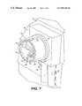
- FIG. 1is a generally front and partially side perspective view of an exemplary embodiment of the subject invention as configured during use thereof, including enclosure within an external or outer cover;
- FIG. 2is a generally front and partially side perspective view, similar to that of FIG. 1 , of an exemplary embodiment in accordance with the subject invention in isolation from the outer cover thereof, and in isolation from a use configuration thereof;
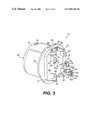
- FIG. 3is a generally rear and partially side perspective view of the illustration of an exemplary a embodiment as in FIG. 2 , and showing in exploded view alternative modular plug features thereof;
- FIG. 4is a fully exploded view of the exemplary embodiment as represented in present FIG. 3 , with certain features shown in partial cutaway and in phantom lines for better illustrating the features thereof;
- FIG. 5is a generally front view, with slight top perspective, with a number of modular aspects of subject embodiments of the subject invention removed, for showing only a baseplate and certain circuitry and support features directly associated therewith;
- FIG. 6is a generally side cross sectional view of the embodiment of present FIG. 5 , taken along the section line 6 — 6 as illustrated in such FIG. 5 , and showing in dotted line the relative position of additional features, including an inner assembly chassis and an inner cover;
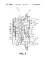
- FIG. 7is a side cross sectional view of the subject matter as in FIG. 6 , with certain additional elements illustrated for forming a first exemplary embodiment in accordance with the subject invention, having relatively lower and upper circuit boards and an electronic display, and with certain metering coil assembly features shown in full for greater detail thereof;
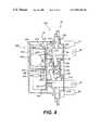
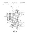
- FIG. 8is a side cross sectional view as in FIG. 7 , and showing features in common with such FIG. 7 and with certain additional features of FIG. 7 removed in favor of a second exemplary embodiment of the subject invention making use of a particular form of mechanical register device involving a cyclometer mechanism;
- FIG. 9is a side cross sectional view as in FIGS. 7 and 8 , and showing a third embodiment of the subject invention making use of an alternative form of mechanical register, involving mechanized gears and dials for a clock-type mechanism;
- FIG. 10is a diagrammatical schematic view of certain baseplate features and corresponding simplified wiring features in accordance with the present invention, including labeling for various of certain diagrammatical representations;
- FIG. 11is a functional schematic of various exemplary power supply features in accordance with the subject invention, and their relation to an exemplary fixed connector in accordance with the subject invention, including labeled diagrammatical representations.
- FIGS. 1 through 3collectively represent generally external features of an exemplary embodiment in accordance with the subject invention.
- FIG. 1provides a generally front perspective and partially side view of a complete device in accordance with the subject invention, provided with an external cover generally 10 and situated for use thereof in a typical arrangement, such as in a residential electric meter setting.
- FIGS. 2 and 3provide generally front and rear perspective views, respectively, and with partial side views, of the subject exemplary embodiment in accordance with the subject invention, but with outer or external cover 10 thereof removed, and isolated from any use environment.
- Apparatus 12may preferably include a baseplate or molded base generally 14 which receives what may be regarded as an inner cover generally 16 .
- Such inner cover 16 featuresare generally shown in dotted line in present FIG. 1 , representing the fact that they are received within the outer or exterior cover 10 .
- FIG. 1illustrates an exemplary typical installation, with an embodiment of the subject invention received within outer cover 10 and mounted to a meter receiving junction box generally 18 .
- box 16is typically mounted on a wall 20 or similar flat surface. Electric wires are provided in and out of box 18 , typically covered with protective pipes or enclosures generally 22 and 24 .
- outer cover 10may be provided with a truncated, generally frusto-conical section generally 26 and integrally included therewith or associated therewith a relatively larger base section 28 for being received about the peripheral protrusions of baseplate 14 .
- Outer cover 10may be secured to meter device 12 with both cover 10 and device 12 captured by box 18 , all in various ways, as well known to those of ordinary skill in the art, and not forming any particular aspects of the present invention.
- outer cover 10is typically transparent. Outer cover 10 may be comprised of glass or various generally transparent plastic materials. Such an external cover 10 provides adequate safety for the ultimate consumers (i.e., the customers of a utility company) as well as the field personnel of the utility company. At the same time, the transparent aspect of such outer cover 10 and several other particular features discussed hereinafter permit continued functional interaction with the device 12 covered thereby.
- cover 16defines a variety of openings, with various uses, functions, and relationships with outer cover 10 .
- Inner cover 16defines a primary opening generally 30 directed towards the front of the cover, primarily for visualizing a register output generally 32 through such opening 30 . As represented in FIG. 1 , because of such opening 30 , the register output generally 32 may be observed through transparent outer cover 10 .
- such opening 30may be preferably defined generally by a semi-circle.
- Such arrangementaccommodates not only the represented exemplary electronic register output generally 32 , but other forms of mechanical register devices, as discussed in greater detail below.
- Two openings generally 34 and 36 on the upper side of inner cover 16accommodate additional functions.
- Opening 34permits insertion by a field operator of a so-called “reset to zero” probe device.
- reset to zeroAs known to those of ordinary skill in the art, such a device resets the entire meter to zero, and is intentionally actuated by field personnel only whenever the entire meter is to be reset to its initial condition, “absolute zero”. Additional details about such devices and their functions are well known to those of ordinary skill in the art without requiring additional discussion, and form no particular aspect of the subject invention.
- Opening 36 defined in accordance with the subject invention through cover 16permits the output of a light pipe, as discussed in greater detail below.
- a light pipe outputmay involve an infrared output normally generated all the time, in order to show a customer (i.e., the utility company personnel) that the meter is operating correctly. It also permits an output by which such customer may verify calibration of the meter, discussed in greater detail below.
- Cover 16may optionally define several additional openings on the front portion thereof. Specifically, an opening generally 38 may be provided for a pair of optical communication ports 40 and 42 . As well known to those of ordinary skill in the art, without requiring additional discussion, such optical ports permit specific devices to be used for communicating with electronic circuitry included within inner case 16 . An enlarged protrusion generally 44 may be formed in transparent outer cover 10 , to permit such optical communications ports to fully operate and function even while configured in the use environment thereof as represented by present FIG. 1 . By having a pair of ports 40 and 42 , simultaneous input and output functions may be conducted. Such functions may include the output of various forms of data detected by meter device 12 , as well as control inputs into electronic circuitry thereof.
- a further opening generally 46may be provided in the front face of inner cover 16 for receipt of an actuating element or switch 48 .
- Such actuator 48may combine with internal circuit board functions for constituting what is referred to in the industry as a “demand reset”. Such optional function may also be thought of as a “monthly reset”, by which a field technician may reset a particular measurement feature, such as might be associated with certain higher level functions on an optional circuit board. For example, a peak usage reading (based on rate of usage rather than cumulative usage) may be presented in a data register, and then cleared or “reset” to begin a subsequent measuring time period.
- FIG. 1represents a pivoting actuation element generally 50 , to which controlled access may be provided, and which may operate through outer cover 10 for actuation of switch 48 , as well known to those of ordinary skill in the art without additional discussion.
- a further optional switch or actuator generally 52may be provided through larger opening 30 , such as for initiating a test sequence conducted in conjunction with operation of a higher level function board included within an exemplary device 12 .
- test button 52is only accessible to field personnel, while outer cover 10 is removed.
- devices in accordance therewithmay generally be field tested (to varying degrees, depending on specific embodiments) though not necessarily field serviced.
- Such a configurationpermits maximum field interpretation of operation and activity, while inherently protecting field personnel from potential dangers arising from exposure to strong currents and/or high voltages as could occur if device 12 were more disassembled while mounted on or associated with box 18 for receipt of power distribution therefrom.
- FIGS. 1 , 2 and 3Another aspect of the exemplary embodiment device 12 of present FIGS. 1 , 2 and 3 is how far the front portion generally 53 of outer case 10 projects outwardly from baseplate generally 14 . The result is a relatively enlarged area generally 56 constituting an underside portion of case 10 .
- a field technicianmay advantageously use the size of case 10 as mechanical leverage by pressing upwardly in the direction of arrow 58 for dislodging device 12 from the receptacles (not shown) situated in box 18 .
- respective spades or plug-in elements 60 , 62 , 64 , and 66 on the back side of baseplate 14are received in corresponding receptacles in box 18 .
- Such spades 60 , 62 , 64 , and 66provide both mechanical support of device 12 relative to box 18 and provide electrical connections for power flowing through (i.e., both in and out of) device 12 .
- a field technicianmay initially insert spades 60 and 62 into their corresponding receiver elements within box 18 , at an angle, and thereafter pivot device 12 downwardly into a flat position relative box 18 so that spades 64 and 66 become seated in their corresponding openings.
- Pressure on area 56 by the technician in the direction of arrow 58reverses such typical insertion technique, for removal of device 12 .
- Any significantly smaller depth of case 10 relative to baseplate 14would correspondingly reduce the mechanical leverage achieved by such pivoting action, and make removal of device 12 relatively difficult in view of the intended relatively tight fit of spades 60 , 62 , 64 and 66 .
- Inner cover 16 and baseplate 14are preferably comprised of any of various non-conductive high impact plastic materials.
- baseplate 14is of a heavier gauge than that of case 16 , for added strength and stability of device 12 .
- baseplate 14may include various orientation notches or slots 68 , 70 , and 72 (element 72 not seen in FIG. 2 ) for desired alignment of device 12 relative to outer case 10 .
- Baseplate 14may also be provided with feet or projections 74 , 76 , 78 , and 80 , simply serving to rest device 12 on the bottom of its base without requiring contact with or mechanical support on spades 60 , 62 , 64 and 66 .
- baseplate 14Another feature of baseplate 14 which may be practiced involves a pivoting hanger member generally 82 .
- Such pivoting elementmay be pivoted about a pivot axis generally 84 so that an opening generally 86 may be selectively extended beyond the edge of notch 68 .
- a field technicianmay temporarily support baseplate 14 and any component secured thereto, for freedom of working with two hands.
- such temporary hangingmay be practiced at various points during manufacture or assembly of a particular embodiment of the subject invention.
- the upper side generally 88 of baseplate 14may support various wiring features in accordance with the subject invention, for conducting electricity to and from spades 60 , 62 , 64 and 66 relative to the remainder of the electrical components of device 12 . Additional illustrations of such specific features appear in further figures below (for example, see FIG. 5 ) and are described in their related discussion.
- FIG. 3illustrates an opening generally 90 which may be formed through the bottom 92 of baseplate 14 into the interior of device 12 .
- opening 90remains unblocked, so as to permit electrical interconnections to be achieved with components otherwise seated inside of a given device 12 .
- the metrology features of device 12may be calibrated (i.e., initialized for proper accuracy during use in a given environment), the details of which form no particular aspect of the subject invention.
- a plugintended as being non-removable.
- a plug 94 or of a form as plug 96is alternatively inserted into opening 90 .
- Both plugs 94 and 96create a link through the otherwise open circuitry supported on the upper side 88 of baseplate 14 . Therefore, use of either plug 94 or 96 enables use of device 12 . Without insertion of one of such plugs, no power via spades 60 , 62 , 64 and 66 would be properly routed to the interior components of device 12 .
- Plugs 94 and 96provide respectively different functions. While neither are intended as being readily removable, plug 94 provides an upper cover generally 98 which is completely insulated from the circuitry otherwise linked by conductive (and interconnected) tongs 100 and 102 of plug 94 . Therefore, insertion of plug 94 creates a tamper evident arrangement. In other words, in order to gain access to the electrical components or functioning of device 12 via baseplate 14 , it is necessary to remove plug 94 . Evidence of such removal will be readily apparent, due to the nature of its fit, wherefore a tamper-evident linkage is established.
- alternative plug 96has a pair of lateral side edge insulated elements 104 and 106 , which laterally surround conductive screw elements 108 and 110 .
- a manufacturermay achieve desired access for manufacturing and initial calibration, and thereafter provide either a tamper-evident embodiment or interior sensing accessible embodiment, as desired by a customer, but with minimal variation to a given design.
- FIGS. 4 through 9inclusive, show various additional details concerning interior components and others of exemplary devices 12 and others in accordance with the subject invention.
- FIG. 4shows an exploded view of the first exemplary embodiment of present FIG. 3 , with partial cutaway of certain features in conjunction with inner case 16 , for greater clarity in such illustration.
- FIG. 5represents a generally front and slightly top perspective view of essentially baseplate 14 in accordance with the subject invention and various power wiring features associated therewith, as well as various support structure elements defined by such baseplate.
- FIGS. 6 through 9are various sectional views.
- FIG. 6illustrates a generally cross sectional view, taken along section line 6 — 6 in present FIG. 5 .
- FIG. 6illustrates in solid lines the elements of present FIG. 5 , and illustrates in dotted lines the position of the inner cover 16 and an inner assembly chassis as it would be situated during use.
- FIGS. 7 , 8 , and 9respectively show a first embodiment involving an electronic register assembly, a second embodiment involving a cyclometer register mechanical assembly, and a third embodiment having a clock register mechanical assembly.
- the illustrations of present FIGS. 7 through 9show a cross section similar to that as in FIG. 6 .
- Coil assembly featuresare shown in full in FIGS. 7 through 9 , rather than in cross section, for additional detail thereof. While the features shown in phantom line in FIG. 6 continue to be shown in phantom line in FIGS. 7 through 9 , the additional solid line illustrations in FIGS. 7 through 9 represent the alternative register assemblies as may be practiced in such exemplary embodiments in accordance with the subject invention.
- FIG. 4The exploded view of FIG. 4 is largely self-explanatory to one of ordinary skill in the art, in that respective alignments of the various components for forming a modular meter configuration and corresponding methodology in accordance with the subject invention are fully illustrated.
- respective openings 116 , 118 , 120 , and 122are provided for respective spades 60 , 62 , 64 and 66 .
- Such spadesare attached to respective ends of electricity meter coil elements generally 124 and 126 , so as to form a coil assembly.
- Interposed with such coil assemblyis a laminated three legged or “figure 8” core generally 128 and its associated cover generally 130 . Details of such construction and its operation are set forth in various patent subject matter incorporated by reference in the subject application (see above references). See, for example, U.S. Pat. Nos. 5,694,103 and 4,742,296.
- core cover (or support) 130includes flanges with openings 132 and 134 , which openings align and are fitted to upright posts generally 136 and 138 (see FIG. 5 ) for proper receipt and positioning of such elements.
- openings 116 , 118 , 120 and 122By virtue of the predetermined location of openings 116 , 118 , 120 and 122 , and with the fixed position of the ends of coil elements 124 and 126 relative to contact spades 60 , 62 , 64 and 66 , the positioning of cover 130 with posts 136 and 138 ensures proper alignment of the core 128 and the coils 124 and 126 for electricity meter operations, as understood by those of ordinary skill in the art.
- Such postspreferably amount to splined tapered mating or mounting posts, which are preferably ultrasonically welded to the components which they support, for keeping all elements stable relative to one another.
- Other forms of securementmay be practiced, such as gluing or other non-detrimental forms of welding and/or attachment.
- a first or basic integrated circuit board generally 140is a first or basic integrated circuit board generally 140 .
- all componentsare on one side of such circuit board 140 , and comprise the basic kilowatt hour metrology function, as well understood by those of ordinary skill in the art. See also various of the above-referenced U.S. patents for additional was background information.
- first or basic metrology circuit board 140is provided with a pair of openings generally 142 and 144 for correspondence and receipt in stacked fashion on posts 136 and 138 . Such arrangement creates proper alignment of the gap within the center leg of core 128 relative to an appropriate electrical device supported on printed circuit board 140 . As illustrated, notches generally 146 and 148 may be provided to fit around lateral legs of core 128 , once the device 12 is assembled. Specifically in accordance with the subject invention, it should be understood that board 140 may carry electrical devices such as a Hall cell sensor 141 which, due to predetermined positioning per the subject invention, becomes properly located relative to the flux path associated with core 128 , for desired sensing purposes.
- electrical devicessuch as a Hall cell sensor 141 which, due to predetermined positioning per the subject invention, becomes properly located relative to the flux path associated with core 128 , for desired sensing purposes.
- Circuit board generally 140may include a further opening 150 defined therein for receipt of a further support post generally 152 (see FIG. 5 ).
- Such three hole arrangement for board 140(holes 142 , 144 , and 150 ) provides a highly stable three-point support reference for such standard or basic metrology circuit board.
- resilient connectorsare placed on top side surface 88 of baseplate 14 .
- three cantilevered spring connector elements 154 , 156 and 158are provided for operative interaction with select points on underside generally 160 of circuit board 140 , when properly positioned (after assembly) for making electrical connections with such board 140 .
- connectionsare made from spades 60 , 62 , 64 and 66 with circuit board 140 via resilient connectors 154 , 156 and 158 . Additional description of such connections appears below with reference to FIGS. 10 and 11 .
- FIG. 4further represents use of a second or optional higher level function circuit board 162 .
- a variety of alternative functionsmay be included within such a board (generally well known to those of ordinary skill in the art) for providing “personality” or customization of the entire device 12 to meet the needs of a particular customer.
- all required power and signal transmissions needed for second or higher level function circuit board 162may be provided via use of a fixed connector generally 164 .
- Such a fixed connectorinterconnects the boards edge to edge. In doing so, additional support is provided on one side generally 166 of second board 162 .
- FIG. 4illustrates fixed connector 164 in solid lines in a normally exploded view position thereof for receipt of an area generally 168 of first circuit board 140 .
- FIG. 4also shows a dotted line position generally 164 ′ of such fixed connector illustrating its relationship and support of edge 166 of second board 162 .
- fixed connector 164communicates a variety of channels of power and information up to a second circuit board generally 162 (with all channels adequately shielded relative to one another). In a presently preferred exemplary embodiment, seven channels are provided, as discussed in greater detail below with reference to present-FIG. 11 .
- chassis 170A further element which may be thought of as an inner assembly chassis 170 is provided in accordance with the subject invention. Basically, such chassis 170 and all other non-conductive elements (except circuit boards or other electrical components) within device 12 may be formulated from various plastic materials, in accordance with the gauge and durability desired for particular embodiments.
- Chassis 170includes a number of female receptacles defined on an underside generally 172 thereof for corresponding receipt of aligned support posts from the upper side 88 of baseplate 14 .
- relatively larger female receptacles 174 and 176are provided for mating receipt of relatively larger support posts 136 and 138 , respectively.
- a plurality of generally smaller, paired female receptacles 178are provided for corresponding interface with corresponding plurality of support posts generally 180 , again on the upper side 88 of baseplate 14 .
- Another relatively smaller post generally 182is aligned for receipt of upright post 152 (discussed in greater detail above in conjunction with first circuit board 140 ).
- chassis 170“caps” the various support posts of baseplate 14 , whether otherwise used or not. Therefore, a tight, secure, and stable arrangement is provided, without the use of any screws or other individual fastening elements.
- circuit board 162may be provided with additional openings 184 and 186 (see FIG. 4 ), which correspondingly receive projecting fingers 188 and 190 of a display holding element generally 192 .
- Additional fingers 194 and 196 of such display holder 192interact with a generally upper edge 198 of board 162 .
- display holder 192is secured to second circuit board 162 in the overall arrangement without requiring any respective individual attachment elements or fasteners.
- Lateral edges generally 200 and 202 of board 162may be held by respective fingers 204 and stop elements 206 of chassis 170 . It should be understood by those of ordinary skill in the art that such corresponding fingers 204 and stop elements 206 of chassis 170 as to lateral edge 202 of board 162 are generally not visible in the FIG. 4 illustration. Therefore, the position of board 162 is secured with a “snap fit” arrangement while the electrical connections thereof are secured at least partly through fixed connector 164 (discussed in greater detail below with reference to present FIG. 11 ).
- chassis 170may be involved with securement of alternative registers or devices in place of second board 162 and/or display holder 192 .
- fingers 208 and stops 210 of chassis 170may be involved with securement of alternative registers or devices in place of second board 162 and/or display holder 192 .
- opening and surface of chassis 170contributes to its support and/or guide function in one or more alternative configurations of the subject invention.
- chassis 170Yet another support feature of chassis 170 is extension 212 , which functions to properly position an optical light pipe generally 214 , extending between a corresponding light emitting device 215 on first circuit board 140 and inner case opening generally 36 (see FIGS. 1 , 2 , and 4 ). Examples of the specific functions of such light pipe will be discussed in greater detail below.
- Still additional fingers or projections 216are provided on four relatively outer corners of chassis 170 for securing inner case 16 thereto through interaction with corresponding openings 218 of such case 16 .
- ultrasonic welding of female receptacles 174 , 176 , 178 and 182 of chassis 170 with corresponding upright mating/mounting posts 136 , 138 , 152 and 180 of baseplate 14results in complete securement of all internal features of device 12 once inner cover 16 is secured.
- FIG. 5additionally shows certain aspects of power supply features in accordance with the subject invention, as supported relative to baseplate 14 .
- a varistor generally 220may be received on upper side 88 of baseplate 14 and connected via respective leads 222 and 224 and other power supply network circuitry, as discussed in greater detail below with reference to present FIGS. 10 and 11 .
- a capacitor 226may be received on upper side 88 of baseplate 14 and connected by respective leads 228 and 230 to remaining power supply circuitry, again as discussed in greater detail with reference to present FIGS. 10 and 11 .
- the upper side 88 of baseplate 14may be provided with various projections (no reference characters indicated) for securing the position of such elements, varistor 220 and capacitor 226 .
- FIGS. 6 through 9inclusive, show various cross sectional illustrations, primarily referencing previously discussed subject matter while illustrating variations involved among different embodiments of the subject invention. Accordingly, it is to be understood that repeat use of reference characters is intended to encompass the prior discussion of such features, as applicable to such corresponding features.
- FIG. 6illustrates in solid line a side cross sectional view of the features illustrated in present FIG. 5 , taken along section line 6 — 6 shown therein. Additional features represented in dotted line or phantom primarily relate to various aspects of inner cover 16 and inner assembly chassis 170 .
- One aspect of present FIG. 6is that it illustrates the availability of additional space, such as in general area 232 thereof, within which additional optional features may be received, such as a modem (not shown) for transmission of data via telephone lines.
- FIG. 7provides an identical illustration to FIG. 6 , with the addition of various coil assembly features and features specifically for the above-referenced first embodiment of the subject invention, involving two integrated circuit boards and corresponding solid state circuitry and an electronic register for data output.
- FIGS. 7 through 9depict inclusion of full view illustrations in FIGS. 7 through 9 (rather than cross sections) of core elements 124 and 126 , laminated core 128 and core cover (or support) 130 results in blocked viewing of cantilevered connectors 154 and 156 .
- the additional elements illustrated in present FIG. 7 relative to FIG. 6 so as to illustrate a more complete first embodiment of device 12 in accordance with the subject inventiongenerally include the following. First, the basic function or first circuit board 140 is shown, as used in combination with the customized feature or second circuit board generally 162 .
- circuit board 162is held by various fingers 204 of chassis 170 cooperating with stop elements generally 206 thereof.
- a display holder 192is secured to such second circuit board 162 by respective projections or fingers 190 and 196 .
- Register output 32is held by display holder 192 .
- first embodimentincludes a representation of fixed connector 164 , conveying power and data from first circuit board 140 to second circuit board 162 , as generally discussed above.
- FIG. 7also includes illustrations of spades 60 and 64 , which are the spades in the forefront, when viewing device 12 from the right side, in keeping with the more full illustration of such features and the core and the coil assembly features, rather than a cross sectional view thereof.
- FIGS. 8 and 9are respective mechanical register assemblies. Specifically, FIG. 8 represents a second embodiment of the subject invention generally device 234 while FIG. 9 illustrates generally a third embodiment of the subject invention device generally 236 . Such second and third devices may comprise cyclometer register mechanical assembly and clock register mechanical assembly devices, respectively. Details of various such assemblies are noted in pertinent ones of the above-referenced patents, incorporated herein by reference, and form no particular details of the subject invention beyond the context of the disclosures herewith.
- both such embodimentsinclude full illustrations of spades 60 and 64 , coil elements 124 and 126 , laminated core 128 and core cover 130 , such that cantilevered connectors 154 and 156 are no longer visible. Since both exemplary embodiments 234 and 236 of FIGS. 8 and 9 respectively involve various mechanical assemblies, there are no illustrations (as in FIG. 7 ) for second board 162 , display holder 192 or its associated fingers 190 and 196 , electronic register output 32 , or fixed connector 164 .
- the second embodiment device 234 of FIG. 8may include a mechanical wheel assembly, with numbers mounted on a wheel mounting to fingers or extensions of the support chassis 170 .
- exemplary wheel generally 238represents a plurality of such wheels laterally disposed adjacent one another for providing mechanical register output.
- such plurality of wheels 238may be supported within an integral structure, such as having a rear wall generally 240 and front wall 242 thereof.
- a pair of upper curved fingers generally 244(only one shown due to the cross sectional nature of FIG. 8 ) capture an upper edge of rear or back wall generally 240 of the integral cyclometer mechanical register assembly generally 246 .
- Such curved fingers 244are preferably integrally formed with chassis 170 , which also provides a pair of lower capture elements generally 248 (only one shown due to the cross sectional nature of FIG. 8 ) for capturing a lower edge of back or rear wall 240 of mechanical register assembly 246 .
- the cantilevered curved nature of upper fingers 244permit a field technician or manufacturing personnel to flex the curved fingers 244 for introducing or alternately removing mechanical assembly register 246 .
- the inner cover 16may be applied, as otherwise understood from the remainder of the specification.
- the mechanical register assembly device embodiment 236 of present FIG. 9is similar to that of present FIG. 8 , but has its own form of mechanical register assembly generally 250 .
- Such mechanical register 250may comprise a clock register type of assembly, well known to those of ordinary skill in the art.
- Such assembly 250may preferably comprise an integral arrangement having rear and front walls 252 and 254 , respectively.
- the rear wallmay be captured or secured by chassis 170 , including an upper pair of elements 208 thereof, and intermediate pairs of fingers 204 thereof, cooperating with both pairs of stop elements 206 .
- Exemplary support elements 256 and 258represent mechanical support between rear wall 252 and front wall 254 of mechanical register assembly 250 .
- a plurality of relatively smaller dial elements generally 260are driven clock-style in respective scaled relationships via a series of gears, represented by dotted line generally 262 , and mounted generally in parallel with the respective rear and front walls 252 and 254 of integral mechanical assembly 250 .
- alternate dialsare rotated either clockwise or counterclockwise.
- gears generally 262are motor driven, as are the respective plurality of wheels 238 of cyclometer register mechanical assembly generally 246 .
- a basic wire connection between the motor drive of respective mechanical assemblies 250 and 246may be interconnected with the main or basic metrology circuit board 140 , for driving same.
- One convenient alternative interconnection for such power (or drive control)may be obtained by the securement of a connector generally to the area 168 of circuit board 140 (not seen in FIGS. 8 and 9 ).
- FIG. 10represents a simplified wiring diagram involving power supply aspects and others of the subject invention.
- the four spades or plug-ins 60 , 62 , 64 and 66are representative of the paired line inputs and paired load outputs, as illustrated by the schematic diagram.
- representations of the full coil assembly including coil members 124 and 126 , and laminated core 128 and core cover 130are omitted.
- respective coil elements interconnect input spade 60 with output spade 64 and interconnect input spade 62 with output spade 66as generally represented by schematic dotted line elements 264 and 266 , respectively.
- FIG. 10schematic diagram represents three respective terminal points 268 , 270 and 272 .
- Such terminal pointsrespectively correspond, for example, with the three respective cantilevered contacts 154 , 156 and 158 (see FIG. 5 ) for creating contacts with the first circuit board (or basic metrology board) generally 140 .
- terminal contacts 268 , 270 and 272comprise inputs to the metrology board 140 , such that both Line 1 and Line 2 inputs (taken directly from spades 62 and 60 , respectively) are provided to circuit board 140 , as well as a denominated power supply (“P.S.”) input.
- P.S.denominated power supply
- varistor generally 274functions as well known to those of ordinary skill in the art for shunting any line disturbances and for generally protecting the overall wiring circuitry.
- the nominal voltage across Lines 1 and 2is 240 volts AC (VAC).
- VAC240 volts AC
- a varistorprovides a variable resistance, dependent on an applied voltage level, and therefore provides the above-referenced shunting and protective functions.
- a reduced “power supply” voltage of nominally 12 volts ACis provided at P.S. terminal 270 through use of P.S. capacitor generally 276 , as represented by the circuitry arrangement of the schematic representations of present FIG. 10 .
- a capacitor value of 0.33 microfaradsthe nominal 240 volts AC is dropped to 12 volts AC at contact point P.S. 270 .
- a capacitoracts as an open circuit to DC voltage and otherwise provides a responsive circuit element to AC voltages due to the alternate charging and discharging nature of a capacitor. It is to be understood that different values of components indicated herein or other arrangements for obtaining a power supply may be utilized in accordance with the broader aspects of the subject invention.
- the schematic diagram of FIG. 10further represents the opening 90 (see FIG. 4 ) associated with baseplate 14 .
- an open circuit pointis still provided by the opening 90 feature.
- the metrology functionmay then be calibrated for the specific physical arrangement of components as implemented on a given device by a given arrangement of the subject invention. Calibration may include “programming” the device with a slight correction factor to account for such specific physical embodiment. After such operation, either one of alternative modular plugs 94 and 96 (see FIG. 3 and its related discussion) may be seated within opening 90 , so that the otherwise open circuit is completed for normal field operation, with calibration complete.
- FIG. 11is a block diagram representation of additional power supply features and other features in accordance with the subject invention, including their relation to powering the metrology function and “communicating” among basic circuit board 140 and any other circuit boards associated therewith, such as via a fixed connector generally 164 .
- FIG. 11represents the entire metrology board generally 140 in dotted line block diagram fashion, and likewise represents fixed connector generally 164 .
- a portion of the features of each such component metrology board 140 and fixed connector 164are further diagrammatically represented within their dotted line block diagram representations.
- respective terminal contact points 268 , 270 , and 272are illustrated in FIG. 11 as all contacting with metrology board 140 .
- preferably such contactsinclude cantilevered extending connections (generally 154 , 156 and 158 , respectively) that are brought into contact with metrology board 140 whenever it is seated in its desired position relative the coil assembly and other features in accordance with the subject invention.
- a power supply networkgenerally 278 .
- such power supply network 278receives at least two inputs, via Line 1 terminal contact 268 (nominally 240 VAC) and the power supply P.S. terminal contact 270 (nominally 12 VAC).
- Power supply networkswhich may be carried on circuit boards are well known to those of ordinary skill in the art, and particular details of power supply network 278 form no particular aspect of the subject invention. See also various patents incorporated herein by reference, as referenced above.
- power supply network 278operates on the inputs thereto for outputting plus or minus 2.5 volts DC (VDC).
- VDCplus or minus 2.5 volts DC
- fixed connector 164preferably engages an edge area generally 168 of metrology board 140 , for achieving various connections therewith.
- respective terminal positions B and C of fixed connector generally 164correspond respectively with the plus and minus 2.5 VDC outputs of power supply network 278 .
- a Line 1 ground connectionis also carried down to fixed connector 164 at terminal A thereof (see FIG. 11 ).
- Metrology board 140also carries circuit board components for performing the basic kilowatt hour data function of a device in accordance with the subject invention. Such actual function is represented by metrology network 280 , examples of which are well known to those of ordinary skill in the art and details of which form no particular aspect of the subject invention. See also various patents incorporated herein by reference, as referenced above.
- Metrology network 280has at least four other outputs, three of which are associated with terminals of fixed connector 164 as illustrated, and a fourth via line 282 which directly outputs an available motor output signal, such as for driving any mechanical register assemblies (see FIGS. 8 and 9 and their related discussion).
- the output signal coming from metrology network 280 to terminal D of fixed connector 164constitutes a sign (+ or ⁇ ) indicative of the direction of power flow (which is typically negative during a consumption mode and plus during any production mode, such as where power is being put back on to the grid by the ultimate customer).
- the output of metrology network 280 resulting in terminal E of fixed connector 164relates to a pulse output, reflecting data generation by the metrology network 280 .
- Such pulse output Emay be utilized for various functions. For example, it may be utilized to modulate an infrared LED 215 associated with light pipe 214 (see discussion above) for providing a signal external to casings for a device in accordance with the subject invention. A customer (for example utility company field personnel) may check such pulse signal for proper operation of the meter without interruption thereof.
- fixed connector 164is also interconnected with any other circuit boards being utilized, such as an exemplary second circuit board 162 (see FIG. 4 and its related discussion). Accordingly, such pulse output signal E is being passed to such higher level function circuit board for possible use there.
- metrology network 280generates on terminal F of fixed connector 164 a digital clock synchronization pulse, such as a 60 Hertz square wave, which is passed via such connector 164 to any further circuit boards for use thereby.
- a digital clock synchronization pulsesuch as a 60 Hertz square wave
- line power(240 VAC), power supply voltage (plus or minus 2.5 VDC) and various data and clocking information is transmitted via fixed connector 164 to a further circuit board, such as high level function board 162 .
- a further circuit boardsuch as high level function board 162 .
- Such communicationis one-way, meaning that the subsequent circuit board makes use as needed of such power and data, without necessarily reflecting any feedback along fixed connector 164 to metrology board 140 .
- the diagrammatic representation of fixed connector 164 in FIG. 11omits for clarity the further connections that would be made from such connector to additional circuit boards, as represented in other figures herewith and explained in their related discussion.
- Another aspect of certain embodiments of the present inventionis that all flexible leads have been eliminated throughout the devices. This means that a highly stable configuration is provided.
- the coil elementsdo not touch the core 128 ( FIG. 4 ) or core cover 130 (FIG. 4 ).
- the respective holes and posts relative to the baseplatehelp align the core and coil.
- Introduction of a calibration factortakes care of fine tuning or exact position inaccuracies. Otherwise, the subject exemplary arrangements help provide fixture to the basic flux path utilized for metrology operations.
- ultrasonic weldingbe utilized to capture all of the basic components in place once fully assembled as desired.
- opening 90 provided in baseplate 14prior to introduction of either of alternative plugs 94 and 96 )
- the subject metering devicecan still be calibrated for precision.
- the multiple size steps and splined postsinitially help align and fit the circuit board to the laminated core, and align other elements, so that all basic desired relationships are established, and then fine tuned by such calibration.
- any second (or additional) circuit board(s)may be provided with plus or minus 2.5 VDC via fixed connector 164 , in some embodiments such additional boards may make use of their own power supply. All such modified embodiments, as may be desired for a user in a particular circumstance, are intended to come within the broader spirit and scope of the subject invention.
- light pipe 214(see FIG. 4 and others) is generally shown as a straight shaft. In the illustrated embodiments, it isolates the output of a particular infrared LED 215 for showing that the lower or basic metrology board 140 is properly working.
- the light pipemay be more S-shaped instead of just straight, to accommodate desirable modifications in the internal component arrangements of a given embodiment.
- an antenna 261may be provided directly onto a circuit board (such as additional or second circuit board 162 ) for radiating metering information directly from such circuit board without requiring a second antenna.
- a circuit boardsuch as additional or second circuit board 162
- Any such arrangementmay involve greater frequency communications both in and out, meaning that some devices may permit the high level functions of an additional circuit board to be queried by a field technician or reader, for calling for various forms of output, or otherwise controlled or reprogrammed by communications in.
- such higher level function boardsmay incorporate a non-volatile memory for maintaining determined data even during power outages.
- pulse outputterminal E of fixed connector 164 —FIG. 11
- Such outputis two fold in that it permits and enables the light pipe form of output (as referenced above) and the communication of a basic metrology signal from lower or basic metrology board 140 to a higher order or higher level function circuit board generally 162 .
- such higher level circuit boardmay be provided with connections for optical ports (see elements 40 and 42 of present FIGS. 1 and 2 ), by which communications may also be directed in and out of the electric meter.
- telephone line connectionsmay be provided by including a modem within a given device, both with wires or with wireless transmission, such as cellular telephone service.
Landscapes
- Physics & Mathematics (AREA)
- General Physics & Mathematics (AREA)
- Engineering & Computer Science (AREA)
- Power Engineering (AREA)
- Optics & Photonics (AREA)
- Arrangements For Transmission Of Measured Signals (AREA)
- Measuring Pulse, Heart Rate, Blood Pressure Or Blood Flow (AREA)
- Coupling Device And Connection With Printed Circuit (AREA)
- Vehicle Body Suspensions (AREA)
- Telephone Set Structure (AREA)
Abstract
Description
Claims (58)
Priority Applications (13)
| Application Number | Priority Date | Filing Date | Title |
|---|---|---|---|
| US09/450,890US6885185B1 (en) | 1998-12-01 | 1999-11-29 | Modular meter configuration and methodology |
| AU19242/00AAU1924200A (en) | 1998-12-01 | 1999-11-30 | Modular meter configuration and methodology |
| AT99962894TATE412914T1 (en) | 1998-12-01 | 1999-11-30 | MODULAR COUNTER ARRANGEMENT AND METHOD FOR USE THEREOF |
| BR9915473-0ABR9915473A (en) | 1998-12-01 | 1999-11-30 | Modular electricity meter set |
| PCT/US1999/028121WO2000033090A1 (en) | 1998-12-01 | 1999-11-30 | Modular meter configuration and methodology |
| EA200100605AEA200100605A1 (en) | 1998-12-01 | 1999-11-30 | MODULAR MEASURING DEVICE |
| EP99962894AEP1155332B1 (en) | 1998-12-01 | 1999-11-30 | Modular meter configuration and methodology |
| KR1020017006715AKR100687782B1 (en) | 1998-12-01 | 1999-11-30 | Electricity meter |
| CA2352438ACA2352438C (en) | 1998-12-01 | 1999-11-30 | Modular meter configuration and methodology |
| CNB998138908ACN1178067C (en) | 1998-12-01 | 1999-11-30 | Modular Measuring Table Structure and Manufacturing Method |
| DE69939843TDE69939843D1 (en) | 1998-12-01 | 1999-11-30 | MODULAR COUNTER ASSEMBLY AND METHOD FOR USE THEREOF |
| US11/080,745US7701199B2 (en) | 1998-12-01 | 2005-03-15 | Modular meter configuration and methodology |
| US12/507,157US7847537B2 (en) | 1998-12-01 | 2009-07-22 | Electricity meter with resilient connectors |
Applications Claiming Priority (2)
| Application Number | Priority Date | Filing Date | Title |
|---|---|---|---|
| US11045798P | 1998-12-01 | 1998-12-01 | |
| US09/450,890US6885185B1 (en) | 1998-12-01 | 1999-11-29 | Modular meter configuration and methodology |
Related Child Applications (1)
| Application Number | Title | Priority Date | Filing Date |
|---|---|---|---|
| US11/080,745ContinuationUS7701199B2 (en) | 1998-12-01 | 2005-03-15 | Modular meter configuration and methodology |
Publications (1)
| Publication Number | Publication Date |
|---|---|
| US6885185B1true US6885185B1 (en) | 2005-04-26 |
Family
ID=26808042
Family Applications (3)
| Application Number | Title | Priority Date | Filing Date |
|---|---|---|---|
| US09/450,890Expired - LifetimeUS6885185B1 (en) | 1998-12-01 | 1999-11-29 | Modular meter configuration and methodology |
| US11/080,745Expired - Fee RelatedUS7701199B2 (en) | 1998-12-01 | 2005-03-15 | Modular meter configuration and methodology |
| US12/507,157Expired - Fee RelatedUS7847537B2 (en) | 1998-12-01 | 2009-07-22 | Electricity meter with resilient connectors |
Family Applications After (2)
| Application Number | Title | Priority Date | Filing Date |
|---|---|---|---|
| US11/080,745Expired - Fee RelatedUS7701199B2 (en) | 1998-12-01 | 2005-03-15 | Modular meter configuration and methodology |
| US12/507,157Expired - Fee RelatedUS7847537B2 (en) | 1998-12-01 | 2009-07-22 | Electricity meter with resilient connectors |
Country Status (11)
| Country | Link |
|---|---|
| US (3) | US6885185B1 (en) |
| EP (1) | EP1155332B1 (en) |
| KR (1) | KR100687782B1 (en) |
| CN (1) | CN1178067C (en) |
| AT (1) | ATE412914T1 (en) |
| AU (1) | AU1924200A (en) |
| BR (1) | BR9915473A (en) |
| CA (1) | CA2352438C (en) |
| DE (1) | DE69939843D1 (en) |
| EA (1) | EA200100605A1 (en) |
| WO (1) | WO2000033090A1 (en) |
Cited By (36)
| Publication number | Priority date | Publication date | Assignee | Title |
|---|---|---|---|---|
| US20050033886A1 (en)* | 2001-09-12 | 2005-02-10 | Udo Grittke | Method for securing the exchange of data between an external access unit and field device |
| US20050162149A1 (en)* | 1998-12-01 | 2005-07-28 | Makinson David N. | Modular meter configuration and methodology |
| US20060158177A1 (en)* | 2002-09-12 | 2006-07-20 | Landis+Gyr, Inc.. | Electricity meter with power supply load management |
| US20060161396A1 (en)* | 2005-01-20 | 2006-07-20 | Electro Industries/Gauge Tech. | System and method for providing universal additional functionality for power meters |
| US20080024115A1 (en)* | 2006-06-14 | 2008-01-31 | Itron, Inc. | Printed circuit board connector for utility meters |
| US20080238711A1 (en)* | 2007-04-02 | 2008-10-02 | Robert Kent Payne | Automated meter reader direct mount endpoint module |
| US20090134863A1 (en)* | 2007-11-27 | 2009-05-28 | Kabushiki Kaisha Toshiba | Electricity meter |
| US20090168307A1 (en)* | 2007-12-26 | 2009-07-02 | Loy Garry M | Mechanical packaging apparatus and methods for an electrical energy meter |
| US20100090680A1 (en)* | 2008-10-10 | 2010-04-15 | Electro Industries/Gauge Tech. | Intelligent electronic device having a terminal assembly for coupling to a meter mounting socket |
| US20100238983A1 (en)* | 2005-01-24 | 2010-09-23 | Electro Industries/Gauge Tech. | System and method for data transmission between an intelligent electronic device and a remote device |
| US20110153238A1 (en)* | 2004-10-27 | 2011-06-23 | Electro Industries/Gauge Tech. | System and method for connecting electrical devices using fiber optic serial communication |
| US20120074927A1 (en)* | 2010-09-02 | 2012-03-29 | Landis+Gyr, Inc. | Electronic Tamper Detection in a Utility Meter Using Magnetics |
| US8437883B2 (en) | 2009-05-07 | 2013-05-07 | Dominion Resources, Inc | Voltage conservation using advanced metering infrastructure and substation centralized voltage control |
| US20130119974A1 (en)* | 2011-11-14 | 2013-05-16 | General Electric Company | System and method for tamper detection in a utility meter |
| US20140180613A1 (en)* | 2012-12-21 | 2014-06-26 | Electro Industries/Gauge Tech | Intelligent electronic device having a touch sensitive user interface |
| US8788882B2 (en) | 2012-02-16 | 2014-07-22 | National Instruments Corporation | Customizing code modules of software and programmable hardware for a test instrument |
| US20150230357A1 (en)* | 2012-09-10 | 2015-08-13 | Endress+Hauser Flowtec Ag | Electronic device having a housing for accommodating electronic components, preferably of a process transmitter |
| US9135131B2 (en) | 2012-02-16 | 2015-09-15 | National Instruments Corporation | Customizing operation of a test instrument based on information from a system under test |
| USD753003S1 (en) | 2015-01-21 | 2016-04-05 | Electro Industries/Gauge Tech | Electronic power meter |
| US9325174B2 (en) | 2013-03-15 | 2016-04-26 | Dominion Resources, Inc. | Management of energy demand and energy efficiency savings from voltage optimization on electric power systems using AMI-based data analysis |
| US9354641B2 (en) | 2013-03-15 | 2016-05-31 | Dominion Resources, Inc. | Electric power system control with planning of energy demand and energy efficiency using AMI-based data analysis |
| US9367075B1 (en) | 2013-03-15 | 2016-06-14 | Dominion Resources, Inc. | Maximizing of energy delivery system compatibility with voltage optimization using AMI-based data control and analysis |
| US9563218B2 (en) | 2013-03-15 | 2017-02-07 | Dominion Resources, Inc. | Electric power system control with measurement of energy demand and energy efficiency using t-distributions |
| US9847639B2 (en) | 2013-03-15 | 2017-12-19 | Dominion Energy, Inc. | Electric power system control with measurement of energy demand and energy efficiency |
| US9897461B2 (en) | 2015-02-27 | 2018-02-20 | Electro Industries/Gauge Tech | Intelligent electronic device with expandable functionality |
| US10048088B2 (en) | 2015-02-27 | 2018-08-14 | Electro Industries/Gauge Tech | Wireless intelligent electronic device |
| US20180328968A1 (en)* | 2017-05-11 | 2018-11-15 | Marc Balich | Exclusive smart electricity meter |
| US10247757B2 (en)* | 2015-07-01 | 2019-04-02 | Honeywell International Inc. | Electricity meter forms module |
| US10260903B2 (en) | 2004-10-05 | 2019-04-16 | Electro Industries/Gauge Tech | Meter having a communication interface for receiving and interfacing with a communication device |
| US10585125B2 (en) | 2015-05-27 | 2020-03-10 | Electro Industries/ Gaugetech | Devices, systems and methods for data transmission over a communication media using modular connectors |
| US10732656B2 (en) | 2015-08-24 | 2020-08-04 | Dominion Energy, Inc. | Systems and methods for stabilizer control |
| US11009922B2 (en) | 2015-02-27 | 2021-05-18 | Electro Industries/Gaugetech | Wireless intelligent electronic device |
| US11201395B2 (en) | 2019-09-09 | 2021-12-14 | Honeywell International Inc. | Camouflaged single branch dual band antenna for use with power meter |
| US11516899B2 (en) | 2015-05-27 | 2022-11-29 | Electro Industries/Gauge Tech | Devices, systems and methods for electrical utility submetering |
| US11536754B2 (en) | 2019-08-15 | 2022-12-27 | Landis+Gyr Innovations, Inc. | Electricity meter with fault tolerant power supply |
| US12431621B2 (en) | 2023-01-26 | 2025-09-30 | Honeywell International Inc. | Compact dual band antenna |
Families Citing this family (27)
| Publication number | Priority date | Publication date | Assignee | Title |
|---|---|---|---|---|
| US8026830B2 (en)* | 2004-09-02 | 2011-09-27 | Boh Technology, L.L.C. | Methods and systems for meter reading and high speed data transfer |
| US7843391B2 (en) | 2006-09-15 | 2010-11-30 | Itron, Inc. | RF local area network antenna design |
| EP2209011A1 (en)* | 2007-10-17 | 2010-07-21 | Jiasheng Wan | A modular electronic energy meter |
| US8013594B2 (en)* | 2007-10-23 | 2011-09-06 | Fluke Corporation | Digital multimeter having hinged shield arrangement |
| WO2009146394A1 (en)* | 2008-05-30 | 2009-12-03 | Itron, Inc. | Actuator/wedge improvements to embedded meter switch |
| US8040664B2 (en) | 2008-05-30 | 2011-10-18 | Itron, Inc. | Meter with integrated high current switch |
| WO2010102189A2 (en)* | 2009-03-06 | 2010-09-10 | James Goings | Power indicator assembly for an electrical box |
| US8279027B2 (en)* | 2009-05-08 | 2012-10-02 | Sensus Spectrum Llc | Magnetic latching actuator |
| US8890711B2 (en) | 2009-09-30 | 2014-11-18 | Itron, Inc. | Safety utility reconnect |
| MX2012003781A (en)* | 2009-09-30 | 2012-06-01 | Itron Inc | Utility remote disconnect from a meter reading system. |
| US8493232B2 (en)* | 2009-09-30 | 2013-07-23 | Itron, Inc. | Gas shut-off valve with feedback |
| US8842712B2 (en) | 2011-03-24 | 2014-09-23 | Gregory C. Hancock | Methods and apparatuses for reception of frequency-hopping spread spectrum radio transmissions |
| US8872506B2 (en) | 2011-10-05 | 2014-10-28 | General Electric Company | Mounting systems for use with meters and method of assembling same |
| US8445803B1 (en)* | 2011-11-28 | 2013-05-21 | Itron, Inc. | High power electrical switching device |
| US20140077950A1 (en)* | 2012-09-17 | 2014-03-20 | Erick Rudaitis | Cover access notification device |
| US9005423B2 (en) | 2012-12-04 | 2015-04-14 | Itron, Inc. | Pipeline communications |
| US9885743B2 (en)* | 2012-12-17 | 2018-02-06 | Itron, Inc. | Electric meter base level printed circuit board |
| US9250270B2 (en) | 2013-03-15 | 2016-02-02 | Itron, Inc. | Electricity meter having multiple hall devices |
| GB2517137B (en)* | 2013-07-11 | 2021-04-14 | Johnson Electric Int Ag | Electrical contactor |
| CN104142414A (en)* | 2014-08-11 | 2014-11-12 | 无锡锐泰节能系统科学有限公司 | Detachable combined electricity meter |
| JP6618370B2 (en)* | 2015-03-05 | 2019-12-11 | エイブリック株式会社 | Magnetic sensor circuit |
| WO2017127249A1 (en)* | 2016-01-22 | 2017-07-27 | Locus Energy, Inc. | Distributed energy generation and consumption monitoring and reporting device with modular communication upgradability and protection domains in hardware |
| CN106771426A (en)* | 2016-12-09 | 2017-05-31 | 深圳市深电能售电有限公司 | A kind of electric data metering terminal for deep electric energy Electric Load Prediction System |
| CN106686925B (en)* | 2016-12-16 | 2022-02-22 | 天津七一二通信广播股份有限公司 | Wall-mountable building block type WIFI device with base |
| US10276939B1 (en) | 2017-11-28 | 2019-04-30 | Mueller International, Llc | Through-the-lid pit antenna |
| DE102020102142B3 (en) | 2020-01-29 | 2021-07-29 | Vega Grieshaber Kg | Display and / or control unit, field device with such a display and / or control unit, retrofit device for a field device and method for displaying an operating state of a field device |
| CN111624381A (en)* | 2020-05-29 | 2020-09-04 | 宁波泰丰源电气有限公司 | Electric energy meter with positioning function |
Citations (49)
| Publication number | Priority date | Publication date | Assignee | Title |
|---|---|---|---|---|
| US3268884A (en) | 1962-10-02 | 1966-08-23 | Transitel Internat Corp | Shaft encoder assembly |
| US3943498A (en) | 1974-09-26 | 1976-03-09 | Westinghouse Electric Corporation | Direct input photoelectric pulse initiator for meter telemetry and recording systems |
| US3964020A (en) | 1975-03-06 | 1976-06-15 | Hughes Aircraft Company | High voltage system with self-test circuitry |
| US4056775A (en) | 1977-01-07 | 1977-11-01 | General Electric Company | Electronic kWh meter having internal power supply and error correction system |
| US4121147A (en) | 1975-01-02 | 1978-10-17 | Sangamo Electric Company | Electric meter for mounting with a standard watthour meter |
| US4298839A (en) | 1978-03-31 | 1981-11-03 | Westinghouse Electric Corp. | Programmable AC electric energy meter having radiation responsive external data interface |
| US4368424A (en)* | 1978-07-11 | 1983-01-11 | Westinghouse Electric Corp. | Mutual inductance current transducer for AC electric energy meters |
| US4415853A (en) | 1978-09-08 | 1983-11-15 | Fisher Berish M | Monitoring device and method for accurately determining and recording present demand of electrical energy |
| US4465970A (en) | 1981-02-26 | 1984-08-14 | General Electric Company | Method and apparatus for multiple rate metering of electrical energy |
| US4467434A (en) | 1981-09-18 | 1984-08-21 | Mcgraw-Edison Co. | Solid state watt-hour meter |
| US4491790A (en) | 1980-02-13 | 1985-01-01 | Westinghouse Electric Corp. | Electric energy meter having a mutual inductance current transducer |
| US4491792A (en) | 1982-12-13 | 1985-01-01 | General Electric Company | Sensing switch for a magnetically coupled communications port |
| US4491789A (en) | 1981-08-14 | 1985-01-01 | Westinghouse Electric Corp. | Electrical energy meter having a cover-mounted time-of-day multifunction register |
| US4509128A (en) | 1982-04-16 | 1985-04-02 | Sangamo Weston, Inc. | Solid-state electrical-power demand register and method |
| US4646003A (en) | 1982-03-05 | 1987-02-24 | Southern California Edison Company, Inc. | Meter testing device |
| US4697182A (en) | 1985-09-16 | 1987-09-29 | Sangamo Weston, Inc. | Method of and system for accumulating verifiable energy demand data from remote electricity meters |
| US4734639A (en) | 1986-05-29 | 1988-03-29 | Westinghouse Electric Corp. | Master metering module with voltage selector |
| US4742296A (en) | 1986-02-10 | 1988-05-03 | Lgz Landis & Gyr Zug Ag | Arrangement for measuring electrical power |
| US4771185A (en) | 1985-07-05 | 1988-09-13 | Manufacture D'appareillage Electrique De Cahors | Power adapter for electrical installations and especially domestic installations |
| US4783623A (en) | 1986-08-29 | 1988-11-08 | Domestic Automation Company | Device for use with a utility meter for recording time of energy use |
| US4794327A (en) | 1983-04-13 | 1988-12-27 | Fernandes Roosevelt A | Electrical parameter sensing module for mounting on and removal from an energized high voltage power conductor |
| US4803484A (en) | 1987-01-16 | 1989-02-07 | Energy Innovations, Inc. | Optically readable and human readable dial |
| US4804957A (en)* | 1985-11-27 | 1989-02-14 | Triad Communications, Inc. | Utility meter and submetering system |
| US4881070A (en) | 1985-06-21 | 1989-11-14 | Energy Innovations, Inc. | Meter reading methods and apparatus |
| US4884021A (en) | 1987-04-24 | 1989-11-28 | Transdata, Inc. | Digital power metering |
| US4904995A (en) | 1986-01-21 | 1990-02-27 | Emerson Electric Co. | Integrated remote electricity meter transponder and combination |
| US4922187A (en) | 1987-02-13 | 1990-05-01 | Appalachian Technologies Corporation | Pulse initiator circuit |
| US4977515A (en) | 1988-08-29 | 1990-12-11 | Rudden Frank G | Load management device and method of use |
| US4979122A (en) | 1989-02-01 | 1990-12-18 | Ge Fanuc Automation North America Inc. | Apparatus and method for monitoring power |
| US5001420A (en)* | 1989-09-25 | 1991-03-19 | General Electric Company | Modular construction for electronic energy meter |
| US5014213A (en) | 1988-04-20 | 1991-05-07 | Domestic Automation Company, Inc. | System for use with polyphase utility meters for recording time of energy use |
| US5027059A (en) | 1989-08-24 | 1991-06-25 | Schlumberger Industries, Inc. | Differential current shunt |
| US5059896A (en) | 1989-09-25 | 1991-10-22 | General Electric Company | Electronic watthour meter |
| US5089771A (en) | 1989-02-15 | 1992-02-18 | Nertec Design | Reading device for a watt-hour meter |
| US5170051A (en) | 1989-06-21 | 1992-12-08 | Manufacture D'appareillage Electrique De Cahors | Elastic gripping optoelectronic sensor for an energy consumption meter |
| US5214587A (en) | 1990-11-28 | 1993-05-25 | Green Richard G | Device for monitoring utility usage |
| US5338996A (en) | 1992-06-25 | 1994-08-16 | Mitsubishi Denki Kabushiki Kaisha | Armature core |
| US5364290A (en) | 1992-03-20 | 1994-11-15 | Schlumberger Canada Limited | Electric utility revenue meter polycarbonate base |
| US5442281A (en) | 1993-06-01 | 1995-08-15 | Enscan, Inc. | Method and apparatus for deriving power consumption information from the angular motion of a rotating disk in a watt hour meter |
| US5469049A (en) | 1993-03-26 | 1995-11-21 | Schlumberger Industries, Inc. | System checking and troubleshooting package for an electronic metering device |
| US5495238A (en) | 1992-03-20 | 1996-02-27 | Schlumberger Canada Limited | Induction watt-hour meter non-intrusive and concealed pulse initiator |
| US5519387A (en) | 1994-04-14 | 1996-05-21 | Motorola, Inc. | Utility meter assembly and remote module and mounting apparatus and assembly |
| US5523677A (en) | 1993-10-12 | 1996-06-04 | Sumitomo Special Metals Co., Ltd. | DC current sensor |
| US5590179A (en) | 1993-02-12 | 1996-12-31 | Ekstrom Industries, Inc. | Remote automatic meter reading apparatus |
| US5694103A (en) | 1996-04-25 | 1997-12-02 | Schlumberger Industries, Inc. | Laminated figure 8 power meter core |
| US5789672A (en) | 1992-06-12 | 1998-08-04 | Abb Kent Plc | Metering assembly with vapor barrier |
| US5877703A (en)* | 1997-08-12 | 1999-03-02 | Badger Meter, Inc. | Utility meter transmitter assembly for subsurface installations |
| US5966010A (en) | 1998-02-09 | 1999-10-12 | Abb Power T&D Company Inc. | Electrical energy meter with snap fit interlocking parts |
| US6476595B1 (en) | 1999-01-27 | 2002-11-05 | Abb Automation Inc. | Advanced instrument packaging for electronic energy meter |
Family Cites Families (25)
| Publication number | Priority date | Publication date | Assignee | Title |
|---|---|---|---|---|
| US3215968A (en)* | 1960-12-21 | 1965-11-02 | Adolf L Herrmann | Printed circuit board connector |
| US3778753A (en)* | 1972-05-05 | 1973-12-11 | Bunker Ramo | Electrical connector |
| US3858961A (en)* | 1973-06-06 | 1975-01-07 | Itt | Printed circuit board connector |
| US3960424A (en) | 1974-10-02 | 1976-06-01 | Amp Incorporated | Multi-contact spring connector for board to board connections |
| US4245876A (en)* | 1976-02-06 | 1981-01-20 | Amp Incorporated | Laminated connector |
| US4521065A (en)* | 1983-09-27 | 1985-06-04 | General Motors Corporation | Socket connector for parallel circuit boards |
| US4634199A (en)* | 1985-01-22 | 1987-01-06 | Itt Corporation | Connector assembly for making multiple connections in a thin space |
| US4747790A (en)* | 1985-07-18 | 1988-05-31 | Hosiden Electronics Co., Ltd. | Connector for printed circuit board |
| US4792677A (en)* | 1986-08-29 | 1988-12-20 | Domestic Automation Company, Inc. | System for use with a utility meter for recording time of energy use |
| EP0282622B1 (en)* | 1987-03-20 | 1989-10-04 | Winchester Electronics Zweigwerk Der Litton Precision Products International Gmbh | Pluggable connector for contacting directly a printed circuit board |
| US5068962A (en)* | 1989-09-25 | 1991-12-03 | General Electric Company | Method of fabricating an energy meter |
| US5015197A (en)* | 1990-05-30 | 1991-05-14 | Amp Incorporated | Electrical connector and cable utilizing spring grade wire |
| JP3305843B2 (en)* | 1993-12-20 | 2002-07-24 | 株式会社東芝 | Semiconductor device |
| CH684215A5 (en)* | 1994-02-04 | 1994-07-29 | Landis & Gyr Business Support | Modularly constructed electricity meter |
| US5484295A (en)* | 1994-04-01 | 1996-01-16 | Teledyne Electronic Technologies | Low profile compression electrical connector |
| GB2300719B (en)* | 1995-05-06 | 2000-02-09 | Siemens Measurements Ltd | Improvements in or relating to electricity meters |
| CA2176625C (en)* | 1995-05-19 | 2008-07-15 | Donald Harold Fergusen | Radio frequency identification tag |
| DE29601526U1 (en) | 1996-01-30 | 1997-06-05 | AEG Zähler GmbH, 31785 Hameln | Housing of an electronic electricity meter |
| GB9708413D0 (en)* | 1997-04-26 | 1997-06-18 | Ampy Automation Digilog | Electrical connection devices |
| US6116957A (en)* | 1997-12-17 | 2000-09-12 | The Whitaker Corporation | Electrical connector for interconnecting two circuit boards |
| US6181294B1 (en)* | 1998-03-17 | 2001-01-30 | Transdata, Inc. | Antenna for electric meter and method of manufacture thereof |
| US6120329A (en)* | 1998-05-08 | 2000-09-19 | The Whitaker Corporation | Modular jack with anti-cross-talk contacts and method of making same |
| US6885185B1 (en)* | 1998-12-01 | 2005-04-26 | Itron Electricity Metering, Inc. | Modular meter configuration and methodology |
| US6120318A (en)* | 1999-01-26 | 2000-09-19 | The Whitaker Corporation | Stacked electrical connector having visual indicator subassembly |
| US6850197B2 (en)* | 2003-01-31 | 2005-02-01 | M&Fc Holding, Llc | Printed circuit board antenna structure |
- 1999
- 1999-11-29USUS09/450,890patent/US6885185B1/ennot_activeExpired - Lifetime
- 1999-11-30EAEA200100605Apatent/EA200100605A1/enunknown
- 1999-11-30DEDE69939843Tpatent/DE69939843D1/ennot_activeExpired - Lifetime
- 1999-11-30ATAT99962894Tpatent/ATE412914T1/ennot_activeIP Right Cessation
- 1999-11-30EPEP99962894Apatent/EP1155332B1/ennot_activeExpired - Lifetime
- 1999-11-30BRBR9915473-0Apatent/BR9915473A/ennot_activeApplication Discontinuation
- 1999-11-30KRKR1020017006715Apatent/KR100687782B1/ennot_activeExpired - Fee Related
- 1999-11-30AUAU19242/00Apatent/AU1924200A/ennot_activeAbandoned
- 1999-11-30CNCNB998138908Apatent/CN1178067C/ennot_activeExpired - Fee Related
- 1999-11-30WOPCT/US1999/028121patent/WO2000033090A1/enactiveIP Right Grant
- 1999-11-30CACA2352438Apatent/CA2352438C/ennot_activeExpired - Fee Related
- 2005
- 2005-03-15USUS11/080,745patent/US7701199B2/ennot_activeExpired - Fee Related
- 2009
- 2009-07-22USUS12/507,157patent/US7847537B2/ennot_activeExpired - Fee Related
Patent Citations (49)
| Publication number | Priority date | Publication date | Assignee | Title |
|---|---|---|---|---|
| US3268884A (en) | 1962-10-02 | 1966-08-23 | Transitel Internat Corp | Shaft encoder assembly |
| US3943498A (en) | 1974-09-26 | 1976-03-09 | Westinghouse Electric Corporation | Direct input photoelectric pulse initiator for meter telemetry and recording systems |
| US4121147A (en) | 1975-01-02 | 1978-10-17 | Sangamo Electric Company | Electric meter for mounting with a standard watthour meter |
| US3964020A (en) | 1975-03-06 | 1976-06-15 | Hughes Aircraft Company | High voltage system with self-test circuitry |
| US4056775A (en) | 1977-01-07 | 1977-11-01 | General Electric Company | Electronic kWh meter having internal power supply and error correction system |
| US4298839A (en) | 1978-03-31 | 1981-11-03 | Westinghouse Electric Corp. | Programmable AC electric energy meter having radiation responsive external data interface |
| US4368424A (en)* | 1978-07-11 | 1983-01-11 | Westinghouse Electric Corp. | Mutual inductance current transducer for AC electric energy meters |
| US4415853A (en) | 1978-09-08 | 1983-11-15 | Fisher Berish M | Monitoring device and method for accurately determining and recording present demand of electrical energy |
| US4491790A (en) | 1980-02-13 | 1985-01-01 | Westinghouse Electric Corp. | Electric energy meter having a mutual inductance current transducer |
| US4465970A (en) | 1981-02-26 | 1984-08-14 | General Electric Company | Method and apparatus for multiple rate metering of electrical energy |
| US4491789A (en) | 1981-08-14 | 1985-01-01 | Westinghouse Electric Corp. | Electrical energy meter having a cover-mounted time-of-day multifunction register |
| US4467434A (en) | 1981-09-18 | 1984-08-21 | Mcgraw-Edison Co. | Solid state watt-hour meter |
| US4646003A (en) | 1982-03-05 | 1987-02-24 | Southern California Edison Company, Inc. | Meter testing device |
| US4509128A (en) | 1982-04-16 | 1985-04-02 | Sangamo Weston, Inc. | Solid-state electrical-power demand register and method |
| US4491792A (en) | 1982-12-13 | 1985-01-01 | General Electric Company | Sensing switch for a magnetically coupled communications port |
| US4794327A (en) | 1983-04-13 | 1988-12-27 | Fernandes Roosevelt A | Electrical parameter sensing module for mounting on and removal from an energized high voltage power conductor |
| US4881070A (en) | 1985-06-21 | 1989-11-14 | Energy Innovations, Inc. | Meter reading methods and apparatus |
| US4771185A (en) | 1985-07-05 | 1988-09-13 | Manufacture D'appareillage Electrique De Cahors | Power adapter for electrical installations and especially domestic installations |
| US4697182A (en) | 1985-09-16 | 1987-09-29 | Sangamo Weston, Inc. | Method of and system for accumulating verifiable energy demand data from remote electricity meters |
| US4804957A (en)* | 1985-11-27 | 1989-02-14 | Triad Communications, Inc. | Utility meter and submetering system |
| US4904995A (en) | 1986-01-21 | 1990-02-27 | Emerson Electric Co. | Integrated remote electricity meter transponder and combination |
| US4742296A (en) | 1986-02-10 | 1988-05-03 | Lgz Landis & Gyr Zug Ag | Arrangement for measuring electrical power |
| US4734639A (en) | 1986-05-29 | 1988-03-29 | Westinghouse Electric Corp. | Master metering module with voltage selector |
| US4783623A (en) | 1986-08-29 | 1988-11-08 | Domestic Automation Company | Device for use with a utility meter for recording time of energy use |
| US4803484A (en) | 1987-01-16 | 1989-02-07 | Energy Innovations, Inc. | Optically readable and human readable dial |
| US4922187A (en) | 1987-02-13 | 1990-05-01 | Appalachian Technologies Corporation | Pulse initiator circuit |
| US4884021A (en) | 1987-04-24 | 1989-11-28 | Transdata, Inc. | Digital power metering |
| US5014213A (en) | 1988-04-20 | 1991-05-07 | Domestic Automation Company, Inc. | System for use with polyphase utility meters for recording time of energy use |
| US4977515A (en) | 1988-08-29 | 1990-12-11 | Rudden Frank G | Load management device and method of use |
| US4979122A (en) | 1989-02-01 | 1990-12-18 | Ge Fanuc Automation North America Inc. | Apparatus and method for monitoring power |
| US5089771A (en) | 1989-02-15 | 1992-02-18 | Nertec Design | Reading device for a watt-hour meter |
| US5170051A (en) | 1989-06-21 | 1992-12-08 | Manufacture D'appareillage Electrique De Cahors | Elastic gripping optoelectronic sensor for an energy consumption meter |
| US5027059A (en) | 1989-08-24 | 1991-06-25 | Schlumberger Industries, Inc. | Differential current shunt |
| US5001420A (en)* | 1989-09-25 | 1991-03-19 | General Electric Company | Modular construction for electronic energy meter |
| US5059896A (en) | 1989-09-25 | 1991-10-22 | General Electric Company | Electronic watthour meter |
| US5214587A (en) | 1990-11-28 | 1993-05-25 | Green Richard G | Device for monitoring utility usage |
| US5364290A (en) | 1992-03-20 | 1994-11-15 | Schlumberger Canada Limited | Electric utility revenue meter polycarbonate base |
| US5495238A (en) | 1992-03-20 | 1996-02-27 | Schlumberger Canada Limited | Induction watt-hour meter non-intrusive and concealed pulse initiator |
| US5789672A (en) | 1992-06-12 | 1998-08-04 | Abb Kent Plc | Metering assembly with vapor barrier |
| US5338996A (en) | 1992-06-25 | 1994-08-16 | Mitsubishi Denki Kabushiki Kaisha | Armature core |
| US5590179A (en) | 1993-02-12 | 1996-12-31 | Ekstrom Industries, Inc. | Remote automatic meter reading apparatus |
| US5469049A (en) | 1993-03-26 | 1995-11-21 | Schlumberger Industries, Inc. | System checking and troubleshooting package for an electronic metering device |
| US5442281A (en) | 1993-06-01 | 1995-08-15 | Enscan, Inc. | Method and apparatus for deriving power consumption information from the angular motion of a rotating disk in a watt hour meter |
| US5523677A (en) | 1993-10-12 | 1996-06-04 | Sumitomo Special Metals Co., Ltd. | DC current sensor |
| US5519387A (en) | 1994-04-14 | 1996-05-21 | Motorola, Inc. | Utility meter assembly and remote module and mounting apparatus and assembly |
| US5694103A (en) | 1996-04-25 | 1997-12-02 | Schlumberger Industries, Inc. | Laminated figure 8 power meter core |
| US5877703A (en)* | 1997-08-12 | 1999-03-02 | Badger Meter, Inc. | Utility meter transmitter assembly for subsurface installations |
| US5966010A (en) | 1998-02-09 | 1999-10-12 | Abb Power T&D Company Inc. | Electrical energy meter with snap fit interlocking parts |
| US6476595B1 (en) | 1999-01-27 | 2002-11-05 | Abb Automation Inc. | Advanced instrument packaging for electronic energy meter |
Non-Patent Citations (2)
| Title |
|---|
| Electronic Metering and Applications into the 90's, Steklac, I. Canadian Electrical Association, Toronto, pp. 3-6, Presented May 1991. |
| Semiconductor Physics & Devices: Basic Principles, 2<SUP>nd </SUP>Edition, Neamen, D. Irwin-McGraw Hill, Boston pp. 156-159, 1997. |
Cited By (84)
| Publication number | Priority date | Publication date | Assignee | Title |
|---|---|---|---|---|
| US7701199B2 (en)* | 1998-12-01 | 2010-04-20 | Itron, Inc. | Modular meter configuration and methodology |
| US20050162149A1 (en)* | 1998-12-01 | 2005-07-28 | Makinson David N. | Modular meter configuration and methodology |
| US20050033886A1 (en)* | 2001-09-12 | 2005-02-10 | Udo Grittke | Method for securing the exchange of data between an external access unit and field device |
| US8745692B2 (en)* | 2001-09-12 | 2014-06-03 | Endress + Hauser Process Solutions Ag | Method for securing the exchange of data between an external access unit and field device |
| US20060158177A1 (en)* | 2002-09-12 | 2006-07-20 | Landis+Gyr, Inc.. | Electricity meter with power supply load management |
| US7135850B2 (en)* | 2002-09-12 | 2006-11-14 | Landis+Gyr, Inc. | Electricity meter with power supply load management |
| US10260903B2 (en) | 2004-10-05 | 2019-04-16 | Electro Industries/Gauge Tech | Meter having a communication interface for receiving and interfacing with a communication device |
| US11815365B2 (en) | 2004-10-05 | 2023-11-14 | Ei Electronics Llc | Meter having a communication interface for receiving and interfacing with a communication device |
| US8481911B2 (en) | 2004-10-27 | 2013-07-09 | Electro Industries/Gauge Tech | System and method for connecting electrical devices using fiber optic serial communication |
| US20110153238A1 (en)* | 2004-10-27 | 2011-06-23 | Electro Industries/Gauge Tech. | System and method for connecting electrical devices using fiber optic serial communication |
| US7953565B2 (en) | 2005-01-20 | 2011-05-31 | Electro Industries/Gauge Tech | System and method for providing universal additional functionality for power meters |
| US20070185666A1 (en)* | 2005-01-20 | 2007-08-09 | Erran Kagan | System and method for providing universal additional functionality for power meters |
| US20110231121A1 (en)* | 2005-01-20 | 2011-09-22 | Electro Industries/Gauge Tech | System and method for providing universal additional functionality for power meters |
| US9410822B2 (en) | 2005-01-20 | 2016-08-09 | Electro Industries/Gauge Tech | System and method for providing universal additional functionality for power meters |
| US20060161396A1 (en)* | 2005-01-20 | 2006-07-20 | Electro Industries/Gauge Tech. | System and method for providing universal additional functionality for power meters |
| US7184904B2 (en)* | 2005-01-20 | 2007-02-27 | Electro Industries/Gaugetech | System and method for providing universal additional functionality for power meters |
| US20090112494A1 (en)* | 2005-01-20 | 2009-04-30 | Electro Industries/Gauge Tech. | System and Method for Providing Universal Additional Functionality for Power Meters |
| US7477998B2 (en) | 2005-01-20 | 2009-01-13 | Electro Industries/Gauge Tech | System and method for providing universal additional functionality for power meters |
| US20100238983A1 (en)* | 2005-01-24 | 2010-09-23 | Electro Industries/Gauge Tech. | System and method for data transmission between an intelligent electronic device and a remote device |
| US8581169B2 (en) | 2005-01-24 | 2013-11-12 | Electro Industries/Gauge Tech | System and method for data transmission between an intelligent electronic device and a remote device |
| US20080024115A1 (en)* | 2006-06-14 | 2008-01-31 | Itron, Inc. | Printed circuit board connector for utility meters |
| US7540766B2 (en) | 2006-06-14 | 2009-06-02 | Itron, Inc. | Printed circuit board connector for utility meters |
| US20110038104A1 (en)* | 2007-04-02 | 2011-02-17 | Itron, Inc. | Automated meter reader direct mount endpoint module |
| US20080238711A1 (en)* | 2007-04-02 | 2008-10-02 | Robert Kent Payne | Automated meter reader direct mount endpoint module |
| US7973673B2 (en) | 2007-04-02 | 2011-07-05 | Itron, Inc. | Automated meter reader direct mount endpoint module |
| US7919960B2 (en)* | 2007-11-27 | 2011-04-05 | Toshiba Toko Meter Systems Co., Ltd. | Electricity meter capable of minimizing the risk of data destruction from lightning or surge |
| US20090134863A1 (en)* | 2007-11-27 | 2009-05-28 | Kabushiki Kaisha Toshiba | Electricity meter |
| US20090168307A1 (en)* | 2007-12-26 | 2009-07-02 | Loy Garry M | Mechanical packaging apparatus and methods for an electrical energy meter |
| US7656649B2 (en) | 2007-12-26 | 2010-02-02 | Elster Electricity, Llc | Mechanical packaging apparatus and methods for an electrical energy meter |
| US8717007B2 (en)* | 2008-10-10 | 2014-05-06 | Electro Industries/Gauge Tech | Intelligent electronic device having a terminal assembly for coupling to a meter mounting socket |
| US20100090680A1 (en)* | 2008-10-10 | 2010-04-15 | Electro Industries/Gauge Tech. | Intelligent electronic device having a terminal assembly for coupling to a meter mounting socket |
| US8577510B2 (en) | 2009-05-07 | 2013-11-05 | Dominion Resources, Inc. | Voltage conservation using advanced metering infrastructure and substation centralized voltage control |
| US8437883B2 (en) | 2009-05-07 | 2013-05-07 | Dominion Resources, Inc | Voltage conservation using advanced metering infrastructure and substation centralized voltage control |
| US9097746B2 (en)* | 2010-09-02 | 2015-08-04 | Landis+Gyr, Inc. | Electronic tamper detection in a utility meter using magnetics |
| US20120074927A1 (en)* | 2010-09-02 | 2012-03-29 | Landis+Gyr, Inc. | Electronic Tamper Detection in a Utility Meter Using Magnetics |
| US8754634B2 (en)* | 2011-11-14 | 2014-06-17 | General Electric Company | System and method for tamper detection in a utility meter |
| US20130119974A1 (en)* | 2011-11-14 | 2013-05-16 | General Electric Company | System and method for tamper detection in a utility meter |
| US8788882B2 (en) | 2012-02-16 | 2014-07-22 | National Instruments Corporation | Customizing code modules of software and programmable hardware for a test instrument |
| US9135131B2 (en) | 2012-02-16 | 2015-09-15 | National Instruments Corporation | Customizing operation of a test instrument based on information from a system under test |
| US9554483B2 (en)* | 2012-09-10 | 2017-01-24 | Endress + Hauser Flowtec Ag | Electronic device having a housing for accommodating electronic components, preferably of a process transmitter |
| US20150230357A1 (en)* | 2012-09-10 | 2015-08-13 | Endress+Hauser Flowtec Ag | Electronic device having a housing for accommodating electronic components, preferably of a process transmitter |
| US20140180613A1 (en)* | 2012-12-21 | 2014-06-26 | Electro Industries/Gauge Tech | Intelligent electronic device having a touch sensitive user interface |
| US10330713B2 (en)* | 2012-12-21 | 2019-06-25 | Electro Industries/Gauge Tech | Intelligent electronic device having a touch sensitive user interface |
| US9367075B1 (en) | 2013-03-15 | 2016-06-14 | Dominion Resources, Inc. | Maximizing of energy delivery system compatibility with voltage optimization using AMI-based data control and analysis |
| US10784688B2 (en) | 2013-03-15 | 2020-09-22 | Dominion Energy, Inc. | Management of energy demand and energy efficiency savings from voltage optimization on electric power systems using AMI-based data analysis |
| US9563218B2 (en) | 2013-03-15 | 2017-02-07 | Dominion Resources, Inc. | Electric power system control with measurement of energy demand and energy efficiency using t-distributions |
| US9582020B2 (en) | 2013-03-15 | 2017-02-28 | Dominion Resources, Inc. | Maximizing of energy delivery system compatibility with voltage optimization using AMI-based data control and analysis |
| US9678520B2 (en) | 2013-03-15 | 2017-06-13 | Dominion Resources, Inc. | Electric power system control with planning of energy demand and energy efficiency using AMI-based data analysis |
| US9847639B2 (en) | 2013-03-15 | 2017-12-19 | Dominion Energy, Inc. | Electric power system control with measurement of energy demand and energy efficiency |
| US11550352B2 (en) | 2013-03-15 | 2023-01-10 | Dominion Energy, Inc. | Maximizing of energy delivery system compatibility with voltage optimization |
| US9887541B2 (en) | 2013-03-15 | 2018-02-06 | Dominion Energy, Inc. | Electric power system control with measurement of energy demand and energy efficiency using T-distributions |
| US11132012B2 (en) | 2013-03-15 | 2021-09-28 | Dominion Energy, Inc. | Maximizing of energy delivery system compatibility with voltage optimization |
| US10775815B2 (en) | 2013-03-15 | 2020-09-15 | Dominion Energy, Inc. | Electric power system control with planning of energy demand and energy efficiency using AMI-based data analysis |
| US10768655B2 (en) | 2013-03-15 | 2020-09-08 | Dominion Energy, Inc. | Maximizing of energy delivery system compatibility with voltage optimization |
| US9553453B2 (en) | 2013-03-15 | 2017-01-24 | Dominion Resources, Inc. | Management of energy demand and energy efficiency savings from voltage optimization on electric power systems using AMI-based data analysis |
| US9354641B2 (en) | 2013-03-15 | 2016-05-31 | Dominion Resources, Inc. | Electric power system control with planning of energy demand and energy efficiency using AMI-based data analysis |
| US10666048B2 (en) | 2013-03-15 | 2020-05-26 | Dominion Energy, Inc. | Electric power system control with measurement of energy demand and energy efficiency using t-distributions |
| US10274985B2 (en) | 2013-03-15 | 2019-04-30 | Dominion Energy, Inc. | Maximizing of energy delivery system compatibility with voltage optimization |
| US10476273B2 (en) | 2013-03-15 | 2019-11-12 | Dominion Energy, Inc. | Management of energy demand and energy efficiency savings from voltage optimization on electric power systems using AMI-based data analysis |
| US9325174B2 (en) | 2013-03-15 | 2016-04-26 | Dominion Resources, Inc. | Management of energy demand and energy efficiency savings from voltage optimization on electric power systems using AMI-based data analysis |
| US10386872B2 (en) | 2013-03-15 | 2019-08-20 | Dominion Energy, Inc. | Electric power system control with planning of energy demand and energy efficiency using AMI-based data analysis |
| USD851525S1 (en) | 2015-01-21 | 2019-06-18 | Electro Industries/Gauge Tech | Electronic power meter |
| USD808837S1 (en) | 2015-01-21 | 2018-01-30 | Electro Industries/Gauge Tech | Electronic power meter |
| USD753003S1 (en) | 2015-01-21 | 2016-04-05 | Electro Industries/Gauge Tech | Electronic power meter |
| US9897461B2 (en) | 2015-02-27 | 2018-02-20 | Electro Industries/Gauge Tech | Intelligent electronic device with expandable functionality |
| US10739162B2 (en) | 2015-02-27 | 2020-08-11 | Electro Industries/Gauge Tech | Intelligent electronic device with surge supression |
| US12087998B2 (en) | 2015-02-27 | 2024-09-10 | Ei Electronics Llc | Wireless intelligent electronic device |
| US10048088B2 (en) | 2015-02-27 | 2018-08-14 | Electro Industries/Gauge Tech | Wireless intelligent electronic device |
| US11641052B2 (en) | 2015-02-27 | 2023-05-02 | El Electronics Llc | Wireless intelligent electronic device |
| US11009922B2 (en) | 2015-02-27 | 2021-05-18 | Electro Industries/Gaugetech | Wireless intelligent electronic device |
| US10274340B2 (en) | 2015-02-27 | 2019-04-30 | Electro Industries/Gauge Tech | Intelligent electronic device with expandable functionality |
| US11644341B2 (en) | 2015-02-27 | 2023-05-09 | El Electronics Llc | Intelligent electronic device with hot swappable battery |
| US12069778B2 (en) | 2015-05-27 | 2024-08-20 | Ei Electronics Llc | Devices, systems and methods for electrical utility submetering |
| US11516899B2 (en) | 2015-05-27 | 2022-11-29 | Electro Industries/Gauge Tech | Devices, systems and methods for electrical utility submetering |
| US10585125B2 (en) | 2015-05-27 | 2020-03-10 | Electro Industries/ Gaugetech | Devices, systems and methods for data transmission over a communication media using modular connectors |
| US10247757B2 (en)* | 2015-07-01 | 2019-04-02 | Honeywell International Inc. | Electricity meter forms module |
| US10732656B2 (en) | 2015-08-24 | 2020-08-04 | Dominion Energy, Inc. | Systems and methods for stabilizer control |
| US11755049B2 (en) | 2015-08-24 | 2023-09-12 | Dominion Energy, Inc. | Systems and methods for stabilizer control |
| US11353907B2 (en) | 2015-08-24 | 2022-06-07 | Dominion Energy, Inc. | Systems and methods for stabilizer control |
| US12235668B2 (en) | 2015-08-24 | 2025-02-25 | Dominion Energy, Inc. | Systems and method for stabilizer control |
| US20180328968A1 (en)* | 2017-05-11 | 2018-11-15 | Marc Balich | Exclusive smart electricity meter |
| US11536754B2 (en) | 2019-08-15 | 2022-12-27 | Landis+Gyr Innovations, Inc. | Electricity meter with fault tolerant power supply |
| US11201395B2 (en) | 2019-09-09 | 2021-12-14 | Honeywell International Inc. | Camouflaged single branch dual band antenna for use with power meter |
| US12431621B2 (en) | 2023-01-26 | 2025-09-30 | Honeywell International Inc. | Compact dual band antenna |
Also Published As
| Publication number | Publication date |
|---|---|
| CN1328643A (en) | 2001-12-26 |
| CA2352438C (en) | 2010-01-26 |
| US20050162149A1 (en) | 2005-07-28 |
| BR9915473A (en) | 2001-10-23 |
| US7847537B2 (en) | 2010-12-07 |
| KR20010099812A (en) | 2001-11-09 |
| ATE412914T1 (en) | 2008-11-15 |
| WO2000033090A1 (en) | 2000-06-08 |
| CA2352438A1 (en) | 2000-06-08 |
| US20090284251A1 (en) | 2009-11-19 |
| EP1155332A4 (en) | 2005-05-18 |
| EA200100605A1 (en) | 2001-12-24 |
| AU1924200A (en) | 2000-06-19 |
| EP1155332A1 (en) | 2001-11-21 |
| EP1155332B1 (en) | 2008-10-29 |
| US7701199B2 (en) | 2010-04-20 |
| DE69939843D1 (en) | 2008-12-11 |
| CN1178067C (en) | 2004-12-01 |
| KR100687782B1 (en) | 2007-02-27 |
Similar Documents
| Publication | Publication Date | Title |
|---|---|---|
| US6885185B1 (en) | Modular meter configuration and methodology | |
| US6816360B2 (en) | Reduced cost automatic meter reading system and method using locally communicating utility meters | |
| US5001420A (en) | Modular construction for electronic energy meter | |
| CA2155539C (en) | Remote automatic meter reading apparatus | |
| CA2654997C (en) | Electrical energy monitor | |
| US6892144B2 (en) | Arrangement for providing sensor calibration information in a modular utility meter | |
| US6844825B2 (en) | Electric energy service apparatus with tamper detection | |
| US7362232B2 (en) | Electrical service disconnect having external interface | |
| US4791362A (en) | Modularized solid state register | |
| BG65749B1 (en) | Electrometer adapted for optical communication with various external devices | |
| US20020084914A1 (en) | Revenue meter arrangement having sensors in mounting device | |
| US20100052655A1 (en) | Self Contained Kilowatt-Hour meter Integral to Standard Load Center | |
| US7421205B2 (en) | Infrared receiver for residential electricity meter | |
| US6747446B1 (en) | Arrangement for providing external access to functionality switches in a utility meter | |
| JP3099297B2 (en) | Signal conditioning connection device for use in electronic energy meters | |
| CN108008345A (en) | Buckle type single-phase electric energy meter on-site calibration instrument | |
| CN106199100A (en) | Building block type intelligent electric energy meter | |
| JPH07509309A (en) | System and method for measuring electrical energy consumption of multiple consumers |
Legal Events
| Date | Code | Title | Description |
|---|---|---|---|
| AS | Assignment | Owner name:SCHLUMBERGER RESOURCE MANAGEMENT SERVICES, INC., G Free format text:ASSIGNMENT OF ASSIGNORS INTEREST;ASSIGNORS:MAKINSON, DAVID N.;PHILPOT, LUDLOW;REEL/FRAME:010558/0156 Effective date:20000204 | |
| AS | Assignment | Owner name:SCHLUMBERGER SEMA INC., GEORGIA Free format text:CHANGE OF NAME;ASSIGNOR:SCHLUMBERGER RESOURCE MANAGEMENT SERVICES, INC.;REEL/FRAME:013718/0449 Effective date:20011231 | |
| AS | Assignment | Owner name:SCHLUMBERGER ELECTRICITY, INC., SOUTH CAROLINA Free format text:ASSIGNMENT OF ASSIGNORS INTEREST;ASSIGNOR:SCHLUMBERGERSEMA INC.;REEL/FRAME:013868/0530 Effective date:20030317 | |
| AS | Assignment | Owner name:WELLS FARGO BANK, NATIONAL ASSOCIATION, AS ADMINIS Free format text:SECURITY AGREEMENT;ASSIGNOR:SCHLUMBERGER ELECTRICITY, INC.;REEL/FRAME:014828/0934 Effective date:20040701 | |
| AS | Assignment | Owner name:ITRON ELECTRICITY METERING, INC., SOUTH CAROLINA Free format text:CHANGE OF NAME;ASSIGNOR:SCHLUMBERGER ELECTRICITY, INC.;REEL/FRAME:014863/0313 Effective date:20040716 | |
| AS | Assignment | Owner name:WELLS FARGO BANK, NATIONAL ASSOCIATION, AS ADMINIS Free format text:AMENDMENT TO GRANTOR NAME CHANGE UNDER SECURITY AGREEMENT;ASSIGNOR:ITRON ELECTRICITY METERING, INC.;REEL/FRAME:015312/0692 Effective date:20041005 | |
| STCF | Information on status: patent grant | Free format text:PATENTED CASE | |
| CC | Certificate of correction | ||
| CC | Certificate of correction | ||
| AS | Assignment | Owner name:ITRON, INC., WASHINGTON Free format text:MERGER;ASSIGNOR:ITRON ELECTRICITY METERING, INC.;REEL/FRAME:017025/0439 Effective date:20060101 | |
| AS | Assignment | Owner name:WELLS FARGO BANK, NATIONAL ASSOCIATION,WASHINGTON Free format text:SECURITY AGREEMENT;ASSIGNOR:ITRON, INC.;REEL/FRAME:019204/0544 Effective date:20070418 Owner name:WELLS FARGO BANK, NATIONAL ASSOCIATION, WASHINGTON Free format text:SECURITY AGREEMENT;ASSIGNOR:ITRON, INC.;REEL/FRAME:019204/0544 Effective date:20070418 | |
| FPAY | Fee payment | Year of fee payment:4 | |
| AS | Assignment | Owner name:ITRON, INC., WASHINGTON Free format text:RELEASE BY SECURED PARTY;ASSIGNOR:WELLS FARGO BANK, NATIONAL ASSOCIATION;REEL/FRAME:026749/0263 Effective date:20110805 | |
| AS | Assignment | Owner name:WELLS FARGO BANK, NATIONAL ASSOCIATION, WASHINGTON Free format text:SECURITY AGREEMENT;ASSIGNOR:ITRON, INC.;REEL/FRAME:026761/0069 Effective date:20110805 | |
| FPAY | Fee payment | Year of fee payment:8 | |
| FPAY | Fee payment | Year of fee payment:12 | |
| AS | Assignment | Owner name:WELLS FARGO BANK, NATIONAL ASSOCIATION, NORTH CAROLINA Free format text:SECURITY INTEREST;ASSIGNORS:ITRON, INC.;ITRON NETWORKED SOLUTIONS, INC.;REEL/FRAME:045017/0893 Effective date:20180105 Owner name:WELLS FARGO BANK, NATIONAL ASSOCIATION, NORTH CARO Free format text:SECURITY INTEREST;ASSIGNORS:ITRON, INC.;ITRON NETWORKED SOLUTIONS, INC.;REEL/FRAME:045017/0893 Effective date:20180105 |