US6883926B2 - Light emitting semi-conductor device apparatus for display illumination - Google Patents
Light emitting semi-conductor device apparatus for display illuminationDownload PDFInfo
- Publication number
- US6883926B2 US6883926B2US10/207,317US20731702AUS6883926B2US 6883926 B2US6883926 B2US 6883926B2US 20731702 AUS20731702 AUS 20731702AUS 6883926 B2US6883926 B2US 6883926B2
- Authority
- US
- United States
- Prior art keywords
- phosphor
- light emitting
- display surface
- light
- emitting semi
- Prior art date
- Legal status (The legal status is an assumption and is not a legal conclusion. Google has not performed a legal analysis and makes no representation as to the accuracy of the status listed.)
- Expired - Lifetime, expires
Links
Images

Classifications
- G—PHYSICS
- G09—EDUCATION; CRYPTOGRAPHY; DISPLAY; ADVERTISING; SEALS
- G09F—DISPLAYING; ADVERTISING; SIGNS; LABELS OR NAME-PLATES; SEALS
- G09F13/00—Illuminated signs; Luminous advertising
- G09F13/20—Illuminated signs; Luminous advertising with luminescent surfaces or parts
- B—PERFORMING OPERATIONS; TRANSPORTING
- B60—VEHICLES IN GENERAL
- B60Q—ARRANGEMENT OF SIGNALLING OR LIGHTING DEVICES, THE MOUNTING OR SUPPORTING THEREOF OR CIRCUITS THEREFOR, FOR VEHICLES IN GENERAL
- B60Q1/00—Arrangement of optical signalling or lighting devices, the mounting or supporting thereof or circuits therefor
- B60Q1/26—Arrangement of optical signalling or lighting devices, the mounting or supporting thereof or circuits therefor the devices being primarily intended to indicate the vehicle, or parts thereof, or to give signals, to other traffic
- B60Q1/30—Arrangement of optical signalling or lighting devices, the mounting or supporting thereof or circuits therefor the devices being primarily intended to indicate the vehicle, or parts thereof, or to give signals, to other traffic for indicating rear of vehicle, e.g. by means of reflecting surfaces
- B—PERFORMING OPERATIONS; TRANSPORTING
- B60—VEHICLES IN GENERAL
- B60Q—ARRANGEMENT OF SIGNALLING OR LIGHTING DEVICES, THE MOUNTING OR SUPPORTING THEREOF OR CIRCUITS THEREFOR, FOR VEHICLES IN GENERAL
- B60Q3/00—Arrangement of lighting devices for vehicle interiors; Lighting devices specially adapted for vehicle interiors
- B60Q3/10—Arrangement of lighting devices for vehicle interiors; Lighting devices specially adapted for vehicle interiors for dashboards
- B60Q3/12—Arrangement of lighting devices for vehicle interiors; Lighting devices specially adapted for vehicle interiors for dashboards lighting onto the surface to be illuminated
- B—PERFORMING OPERATIONS; TRANSPORTING
- B60—VEHICLES IN GENERAL
- B60Q—ARRANGEMENT OF SIGNALLING OR LIGHTING DEVICES, THE MOUNTING OR SUPPORTING THEREOF OR CIRCUITS THEREFOR, FOR VEHICLES IN GENERAL
- B60Q3/00—Arrangement of lighting devices for vehicle interiors; Lighting devices specially adapted for vehicle interiors
- B60Q3/10—Arrangement of lighting devices for vehicle interiors; Lighting devices specially adapted for vehicle interiors for dashboards
- B60Q3/14—Arrangement of lighting devices for vehicle interiors; Lighting devices specially adapted for vehicle interiors for dashboards lighting through the surface to be illuminated
Definitions
- the present inventionrelates generally to light sources. More particularly, the present invention relates to light emitting semi-conductor light sources. The present invention has particular relevance to illumination of a display via a semiconductor device(s).
- LEDsemi-conductor based light emitting diodes and laser diodes, herein after both are generally referred to as LED(s)
- the LEDhas a small size, high efficiency, can emit bright color light, and as a semiconductor element, is not vulnerable to breakage. Also, it has excellent initial driving characteristics and vibration resistance. Furthermore, it can withstand repeated ON/OFF cycling. Consequently, LEDs have been widely used as various types of indicators and light sources.
- LED displayshave been developed, and these light emitting diodes have been used in manufacturing large size LED displays.
- LEDshave monochromatic peak wavelengths
- three LEDs of red, green and bluehave been used in combination to diffuse and blend their colors into white.
- Such LED displayscan operate at low power, have lite weight, and long life.
- the suitable LEDis typically constructed of a semiconductor epistructure light emitting element set in a cup on the tip of a lead frame.
- the light from the light emitting elementis either already in a suitable/visible color (e.g. red) or is absorbed by a phosphor contained in a resin molding that covers the light emitting element.
- the phosphoremits at a wavelength different from the absorbed light (wavelength conversion)
- the light emitting elementemits blue light and the phosphor absorbs the emitted blue light and emits yellow light
- the combination of yellow phosphor light and blue light emitting element lightmakes it is possible to manufacture an LED that can emit white light.
- LED lightis directional and does not evenly illuminate areas without diffusers or other light averaging structures with considerable light loss.
- traditional LED structuresproduce illumination having an intensity pattern, as each LED device shines on a small area and may produce a halo effect via a high intensity spot at the center. This is not visually desirable nor aesthetically pleasing to the eye.
- these undesirable light patternscan light unnecessary areas and detract from the eye's ability to focus rapidly on a display. More particularly, since it is desirable to illuminate only certain numbers, messages, dials, etc. general lighting of the are is unacceptable. Similarly, general lighting on a surface can be problematic since the display targets (e.g. number, words, dials) may have surfaces with varied pitch which general lighting cannot readily illuminate.
- This type of light distributioncan be particularly troublesome when used to illuminate display surfaces, such as dashboards or control devices such as turning indicators. Moreover, areas of high and low light intensity are undesirable.
- an apparatus for illumination of a display surfaceis provided.
- the apparatusis comprised of a display surface including a patterned phosphor or phosphor containing material and at least one light emitting semi-conductor device or laser diode (LED).
- the employed phosphormay be of various compositions generating light of single or different colors.
- the LEDis positioned to cast its generated electromagnetic radiation onto the display surface.
- the phosphor included in the display surfaceis activated in the range of electromagnetic radiation emitted by the LED to produce single or multi-colored characters or shapes on the display surface as desired.
- activation of the LEDprovides electromagnetic radiation which excites the phosphor to create a visible image.
- the imagewill be comprised of letters or numbers or will be comprised of a shaped pattern which provides general illumination of another element such as a gauge, dial, clock, etc.
- the present inventioncan be used to illuminate display readouts, such as a speedometer, by exposing areas of phosphor in desired areas of the display read out to light from the LED and causing the phosphor to excite in the visible region and to illuminate the display.
- the present inventionadvantageously allows the phosphor treated areas to illuminate while the remainder of the display surface remains dark.
- the deviceavoids the use of multiple visible light generating LEDs, which may otherwise require separate phosphor and lensing systems.
- the present devicecan be used advantageously in front or rear illumination apparatus.
- the utilization of various combinations of LEDs and phosphor materialsallows dimmable displays to be created.
- various combinations of phosphor materials and/or LEDscan be used to create multiple color displays.
- Each of these embodimentscan be achieved by a pattern of phosphor material dispersed within the visual display, coated on the surface of the visual display element, or disposed on or in a film laminated on the surface of the visual display element.
- a pattern of phosphor material dispersed within the visual displaycoated on the surface of the visual display element, or disposed on or in a film laminated on the surface of the visual display element.
- other mechanisms for positioning the phosphorare nonetheless envisioned as suitable for the present invention.
- Exemplary, but non-limiting display application suited to the present inventioninclude dashboards, clocks, watches, signs, indicators, etc..
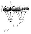
- FIG. 1is a schematic representation of the present invention
- FIG. 2is a schematic representation of an alternative rear illumination embodiment of the present invention.
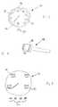
- FIG. 3is an alternative embodiment of the invention wherein divergent phosphor materials are utilized in conjunction with a single radiation generating LED;
- FIG. 4is a further exemplary embodiment of the invention wherein a patterned non-numeric or character display is provided.
- FIG. 5is an alternative embodiment of the invention wherein an LED array is utilized as the illumination source of a patterned phosphor display.
- a front illumination display device 10is depicted comprised of LEDs 12 , and display surface 14 containing patterned phosphor material 16 .
- the display surface 14can be comprised of any material typically utilized in the construction of a display such as wood, metal, polycarbonate or other polymeric material.
- the phosphorcan be molded therein, surface coated, or disposed in a film which is laminated on the substrate surface.
- ultraviolet, or blue light emitting semi-conductor devicessuch as those generated from silicon carbide or gallium nitride can be used.
- LEDblue light emitting semi-conductor devices
- the phosphormay be patterned or the panel may have the equivalent of an etched or punched mask with desired characters etched or stamped in.
- the phosphormay be disposed in a film in this case which bridges the etched character openings.
- unpackaged LEDsConventional LEDs can be used as well as new types of light emitting devices as such new types of LEDs are developed. However, the present invention is best suited, although not limited to, an unpackaged LED.
- the term “unpackaged”is meant to describe LEDs that are derived from the wafer state and may have some electrical connections patterned thereon. However, the unpackaged LEDs do not include an epoxy packaged phosphor containing layer adjacent the semiconductor itself
- any LEDcan be employed, i.e, red, yellow, green, etc., UV and blue are preferred
- a gallium nitride LED of the type described in U.S. Pat. No. 5,998,925 in combination with a phosphorare suitable examples.
- any phosphor excited by any suitable wavelength and emitting any wavelength of lighte.g. red, yellow, green
- the selection of phosphoris limited only by the wavelength of radiation generated by the LED and the desired ultimate viewable light.
- the ultimate visible lightcould be unobservable to the unaided eye but visible via a further device.
- infrared lightcould be generated by the excited phosphor and made visible via suitable view piece to provide observability only to the view piece wearer. This is particularly suited to covert applications
- display device 20includes the display surface 22 as the closest element of the apparatus to the viewer.
- Behind display surface 22is at least substantially 100% transmitting diffuser 24 of any type known to those skilled in the art to provide a coherent pattern upon the patterned phosphor material 26 illuminated surface of the display.
- Rearward of the diffuser 24are LEDs 28 .
- LEDs 28emit light in the blue or UV range.
- display surface 22it is preferably comprised of a material substantially transparent to the range of radiation generated by the LEDs and/or the phosphor creating the image.
- the patterned phosphor materialcan be disposed on the surface of the display closest to the LEDs, embedded in the display material, or disposed on the surface of the display distant from the LEDs.
- the translucence of the display materialfacilitates the transmittance of the electromagnetic radiation as necessary to excite the phosphor material and/or transmit the light generated by the phosphor material as appropriate.
- the phosphorcan be deposited onto the display as a coating, disposed therein, in a film laminated thereon, or via any other technique suitable to the skilled practitioner.
- a filtercan be used to shield the viewer from any wavelength generated by the LEDs.
- a display device 30is depicted wherein divergent phosphor materials are utilized in conjunction with a single wavelength radiation generating LED(s). More particularly, in this embodiment, a speedometer display 32 is provided including speed designation phosphor patterns on the surface 34 . In this embodiment, the phosphor selected for the even numbered speeds will emit in a first color range (e.g. red) and the phosphor selected for the odd number speeds and needle 36 will emit in a second color range (e.g. yellow). This embodiment also exemplifies application of the inventive technique for general illumination of a display surface. Moreover, a phosphor ring 38 is provided surrounding display surface 32 .
- a phosphor ring 38is provided surrounding display surface 32 .
- the phosphor forming ring 38can be used to provide general illumination of the display surface 32 , an effect which could be enhanced via a reflecting element (not shown) surrounding ring 38 . While the phosphors could be selected to be excitable at different radiation wavelengths (see FIG. 5 ) this embodiment uses phosphors exited at the same wavelength and therefore via the same LED(s) device 39 .
- FIG. 4the use of the invention in a general illumination pattern is depicted. Moreover, an LED (not shown) is provided within nob 40 of turning indicated 41 to illuminate a phosphor pattern forming a pair of rings 44 to facilitate location of the nob by the operator of a vehicle. In this embodiment, the light generated via the excitation of the phosphor ring patterns draws attention thereto.
- a display device 50is depicted which is illuminated via an LED array 52 .
- the LED array 52can be used to selectively provide electromagnetic radiation at various wavelengths—in accord with the physical design of the semi-conductor devices or voltage applied thereto—to selectively illuminate different phosphor materials used for miles per hour (MPH) display 54 or kilometers per hour (KPH) display 56 . Accordingly, LEDs A could radiate and excite phosphor material 54 while LEDs B could radiate and excite material 56 . Selectively powering the LEDs therefore selectively illuminates the display. Similarly, LED design or power can be used to provide dimmable capabilities.
- a suitable LED array for this embodimentis described in U.S. Ser. No. 09/258,935.
- a flexible and/or curved substratecan be used.
- the term “flexible”is intended to encompass substrates that are capable of being bent under normal conditions or substrates that can have their shapes altered by processes such as heat forming. In some situations, bending is facilitated by bonding or conforming a substrate to a curved surface. The degree of flexibility will depend on the material properties and the thickness of the substrate (which can be reduced by techniques such as grinding, for example) and, to a limited extent, on the properties of LEDs. Flexible substrates are useful for providing light sources according to the present invention that are conformal to airplane cockpits and automobile dashboards, for example. Similarly, the phosphor containing display device can be flexible.
- a reradiative componentcan be used, particularly, one comprised of a plurality of lenses with each lens being situated over a respective one of the LEDs.
- the reradiative componentcomprises a reradiative panel which may optionally be tinted to create a change in color of light emitted from LEDs.
- Reflector componentscan be used with or without reradiative panels. Although the reflector components are typically parabolic, other optimized reflector component shapes can alternatively be used. As one example, using a stepped profile or a geometric profile can aid in forming a specific pattern of light.
- a control systemcan be used for selecting the manner and timing of providing the electrical power to each respective one of the LEDs.
- a control systemmay be included within a control device, or a control system may be situated outside the substrate.
- AC (alternating current) line voltage(from a 120 volt or 140 volt power supply, for example) is rectified and filtered by rectifier and filter to provide DC voltage.
- a power conditionercan modulate the signal to supply power to LED array at different levels in accordance with a user input or automated selection This can provide flexibility if an operator wants the light source to be dimmed and/or a different display to be illuminated.
- the power conditioners of the control systemscan also aide in LED array cooling by creating a duty cycle for selectively providing power to predetermined LEDs for a set period of time and then switching the power to different ones of the LEDs. Duty cycles can be used both for controlling heat energy and for controlling the light output. For example, alternate row and column or alternate LEDs can be turned on and off per a schedule. If desired, the control system can be extended to accommodate power and/or control features such as shutters.
- a control systemwhether formed from active or passive electronics, can provide flexibility for the light source. For example, if old LEDs change color over time, the amount of power supplied to LEDs and/or the LEDs to which power is supplied can be varied to correct any undesired change in light or to allow the light source to be used in different forms.
- control systemcan also be used to affect tint control, light hue, and color shift by power modulation techniques. Additionally, phase modulation and phase array modulation in combination with a high persistence phosphor (not shown) can provide a lighting glow to remain during low cycles of the power curve.
- the LEDsmay be duty cycled or phased array to give a dimming effect for the display.
- Phosphors or lightcan be chosen to eliminate a non-visible spectra, for covert concealment purposes, such as airplane cockpit or concealed around different situations. In these situations, a heads up display apparatus can be provided to pick up the illumination of the phosphors.
Landscapes
- Engineering & Computer Science (AREA)
- Mechanical Engineering (AREA)
- Physics & Mathematics (AREA)
- General Physics & Mathematics (AREA)
- Theoretical Computer Science (AREA)
- Devices For Indicating Variable Information By Combining Individual Elements (AREA)
- Illuminated Signs And Luminous Advertising (AREA)
Abstract
Description
Claims (18)
Priority Applications (1)
| Application Number | Priority Date | Filing Date | Title |
|---|---|---|---|
| US10/207,317US6883926B2 (en) | 2000-07-25 | 2002-07-29 | Light emitting semi-conductor device apparatus for display illumination |
Applications Claiming Priority (2)
| Application Number | Priority Date | Filing Date | Title |
|---|---|---|---|
| US62512700A | 2000-07-25 | 2000-07-25 | |
| US10/207,317US6883926B2 (en) | 2000-07-25 | 2002-07-29 | Light emitting semi-conductor device apparatus for display illumination |
Related Parent Applications (1)
| Application Number | Title | Priority Date | Filing Date |
|---|---|---|---|
| US62512700AContinuation | 2000-07-25 | 2000-07-25 |
Publications (2)
| Publication Number | Publication Date |
|---|---|
| US20020186556A1 US20020186556A1 (en) | 2002-12-12 |
| US6883926B2true US6883926B2 (en) | 2005-04-26 |
Family
ID=24504697
Family Applications (1)
| Application Number | Title | Priority Date | Filing Date |
|---|---|---|---|
| US10/207,317Expired - LifetimeUS6883926B2 (en) | 2000-07-25 | 2002-07-29 | Light emitting semi-conductor device apparatus for display illumination |
Country Status (1)
| Country | Link |
|---|---|
| US (1) | US6883926B2 (en) |
Cited By (14)
| Publication number | Priority date | Publication date | Assignee | Title |
|---|---|---|---|---|
| US20040189483A1 (en)* | 2003-03-26 | 2004-09-30 | Stringfellow Steven A. | Instrument cluster flood lighting utilizing ultraviolet led |
| US20050207153A1 (en)* | 2004-03-16 | 2005-09-22 | Joel Leleve | Signalling device for automobiles |
| US20070240346A1 (en)* | 2006-03-08 | 2007-10-18 | Intematix Corporation | Light emitting sign and display surface therefor |
| US20090129107A1 (en)* | 2007-11-15 | 2009-05-21 | Novem Car Interior Design Gmbh | Luminous molded part, in particular a decorative part and/or trim part for a vehicle interior |
| US20100110707A1 (en)* | 2008-11-05 | 2010-05-06 | Visteon Global Technologies, Inc. | Ultraviolet Lighted Instrument Panel And Display |
| US20100110657A1 (en)* | 2008-11-05 | 2010-05-06 | Visteon Global Technologies, Inc. | Instrument Panel And Gauge With Ultraviolet Indicia |
| US20110180728A1 (en)* | 2010-01-28 | 2011-07-28 | Yazaki Corporation | Light emission structure for indication symbol in interior space of vehicle |
| USD711585S1 (en) | 2012-05-23 | 2014-08-19 | Paul Jabra | LED strip with flexible support |
| US8998433B2 (en) | 2006-03-08 | 2015-04-07 | Intematix Corporation | Light emitting device utilizing remote wavelength conversion with improved color characteristics |
| US20150226403A1 (en)* | 2013-11-21 | 2015-08-13 | Ford Global Technologies, Llc | Illuminating molding for a vehicle |
| US9347648B2 (en) | 2013-08-28 | 2016-05-24 | Avago Technologies General Ip (Singapore) Pte. Ltd. | Lighting apparatus with transmission control |
| US10023111B2 (en) | 2014-02-19 | 2018-07-17 | Erminia La Vecchia | Illumination device, in particular in a vehicle |
| US10366638B2 (en) | 2014-06-02 | 2019-07-30 | H-3 Group, Inc. | Hybrid photoluminescent lighting display |
| US11623562B2 (en) | 2020-01-15 | 2023-04-11 | Aptiv Technologies Limited | Light control apparatus and method |
Families Citing this family (7)
| Publication number | Priority date | Publication date | Assignee | Title |
|---|---|---|---|---|
| US20020176259A1 (en) | 1999-11-18 | 2002-11-28 | Ducharme Alfred D. | Systems and methods for converting illumination |
| WO2006047306A1 (en)* | 2004-10-22 | 2006-05-04 | Johnson Controls Technology Company | Lamp with emissive material outside of light source |
| US7216997B2 (en)* | 2004-10-26 | 2007-05-15 | Federal-Mogul World Wide, Inc. | Phosphor reactive instrument panel and gauges |
| DE102006029203B9 (en)* | 2006-06-26 | 2023-06-22 | OSRAM Opto Semiconductors Gesellschaft mit beschränkter Haftung | Light Emitting Device |
| US9327643B2 (en) | 2013-11-21 | 2016-05-03 | Ford Global Technologies, Llc | Photoluminescent lift gate lamp |
| DE102014005928A1 (en)* | 2014-04-24 | 2015-10-29 | Diehl Ako Stiftung & Co. Kg | Display device, in particular an electronic household appliance |
| US20160124539A1 (en)* | 2014-10-29 | 2016-05-05 | Whirlpool Corporation | Integrated user interfaces having decorative, touch and lighting elements |
Citations (22)
| Publication number | Priority date | Publication date | Assignee | Title |
|---|---|---|---|---|
| US4044708A (en)* | 1975-07-23 | 1977-08-30 | Mcdonnell Douglas Corporation | Transilluminated dial presentation |
| US4536656A (en) | 1982-04-02 | 1985-08-20 | Nippon Soken, Inc. | Phosphor indication device |
| US4882659A (en) | 1988-12-21 | 1989-11-21 | Delco Electronics Corporation | Vacuum fluorescent display having integral backlit graphic patterns |
| US4999936A (en) | 1988-04-24 | 1991-03-19 | Calamia Thomas J | Illuminated sign |
| US5130597A (en)* | 1991-04-19 | 1992-07-14 | The United States Of America As Represented By The Secretary Of The Army | Amplitude error compensated saw reflective array correlator |
| US5351255A (en) | 1992-05-12 | 1994-09-27 | North Carolina State University Of Raleigh | Inverted integrated heterostructure of group II-VI semiconductor materials including epitaxial ohmic contact and method of fabricating same |
| US5372087A (en) | 1992-08-24 | 1994-12-13 | Nippondenso Co., Ltd. | Analog indicator with self-luminescent pointer |
| US5416674A (en) | 1993-05-31 | 1995-05-16 | Nippon Makisen Kogyo Co., Ltd. | Black light display device |
| US5477430A (en) | 1995-03-14 | 1995-12-19 | Delco Electronics Corporation | Fluorescing keypad |
| US5607222A (en) | 1995-08-21 | 1997-03-04 | Woog; Gunter | Low power illumination device |
| US5614961A (en) | 1993-02-03 | 1997-03-25 | Nitor | Methods and apparatus for image projection |
| US5678917A (en) | 1993-04-29 | 1997-10-21 | Ultralux Ab | Method for providing a white color upon illumination of a fluorescent object with ultraviolet light |
| US5700076A (en) | 1994-07-25 | 1997-12-23 | Proxima Corporation | Laser illuminated image producing system and method of using same |
| US5793911A (en) | 1994-07-08 | 1998-08-11 | Pilkington P.E. Limited | Illumination device |
| US5833349A (en) | 1997-10-25 | 1998-11-10 | Apple; Wayne B. | Phosphorescent lamp shade |
| US5998925A (en) | 1996-07-29 | 1999-12-07 | Nichia Kagaku Kogyo Kabushiki Kaisha | Light emitting device having a nitride compound semiconductor and a phosphor containing a garnet fluorescent material |
| US5997161A (en)* | 1997-12-09 | 1999-12-07 | General Motors Corporation | Black light instrument cluster assembly |
| US6139174A (en) | 1998-08-25 | 2000-10-31 | Hewlett-Packard Company | Light source assembly for scanning devices utilizing light emitting diodes |
| US6299338B1 (en)* | 1998-11-30 | 2001-10-09 | General Electric Company | Decorative lighting apparatus with light source and luminescent material |
| US6357889B1 (en)* | 1999-12-01 | 2002-03-19 | General Electric Company | Color tunable light source |
| US6364498B1 (en)* | 1999-12-22 | 2002-04-02 | Astronics Corporation | Fail-safe illuminated display comprising multimodal illumination components |
| US6454437B1 (en)* | 1999-07-28 | 2002-09-24 | William Kelly | Ring lighting |
Family Cites Families (1)
| Publication number | Priority date | Publication date | Assignee | Title |
|---|---|---|---|---|
| US5988925A (en)* | 1998-10-26 | 1999-11-23 | Baggett; R. Sherman | Stacked paper fastener |
- 2002
- 2002-07-29USUS10/207,317patent/US6883926B2/ennot_activeExpired - Lifetime
Patent Citations (22)
| Publication number | Priority date | Publication date | Assignee | Title |
|---|---|---|---|---|
| US4044708A (en)* | 1975-07-23 | 1977-08-30 | Mcdonnell Douglas Corporation | Transilluminated dial presentation |
| US4536656A (en) | 1982-04-02 | 1985-08-20 | Nippon Soken, Inc. | Phosphor indication device |
| US4999936A (en) | 1988-04-24 | 1991-03-19 | Calamia Thomas J | Illuminated sign |
| US4882659A (en) | 1988-12-21 | 1989-11-21 | Delco Electronics Corporation | Vacuum fluorescent display having integral backlit graphic patterns |
| US5130597A (en)* | 1991-04-19 | 1992-07-14 | The United States Of America As Represented By The Secretary Of The Army | Amplitude error compensated saw reflective array correlator |
| US5351255A (en) | 1992-05-12 | 1994-09-27 | North Carolina State University Of Raleigh | Inverted integrated heterostructure of group II-VI semiconductor materials including epitaxial ohmic contact and method of fabricating same |
| US5372087A (en) | 1992-08-24 | 1994-12-13 | Nippondenso Co., Ltd. | Analog indicator with self-luminescent pointer |
| US5614961A (en) | 1993-02-03 | 1997-03-25 | Nitor | Methods and apparatus for image projection |
| US5678917A (en) | 1993-04-29 | 1997-10-21 | Ultralux Ab | Method for providing a white color upon illumination of a fluorescent object with ultraviolet light |
| US5416674A (en) | 1993-05-31 | 1995-05-16 | Nippon Makisen Kogyo Co., Ltd. | Black light display device |
| US5793911A (en) | 1994-07-08 | 1998-08-11 | Pilkington P.E. Limited | Illumination device |
| US5700076A (en) | 1994-07-25 | 1997-12-23 | Proxima Corporation | Laser illuminated image producing system and method of using same |
| US5477430A (en) | 1995-03-14 | 1995-12-19 | Delco Electronics Corporation | Fluorescing keypad |
| US5607222A (en) | 1995-08-21 | 1997-03-04 | Woog; Gunter | Low power illumination device |
| US5998925A (en) | 1996-07-29 | 1999-12-07 | Nichia Kagaku Kogyo Kabushiki Kaisha | Light emitting device having a nitride compound semiconductor and a phosphor containing a garnet fluorescent material |
| US5833349A (en) | 1997-10-25 | 1998-11-10 | Apple; Wayne B. | Phosphorescent lamp shade |
| US5997161A (en)* | 1997-12-09 | 1999-12-07 | General Motors Corporation | Black light instrument cluster assembly |
| US6139174A (en) | 1998-08-25 | 2000-10-31 | Hewlett-Packard Company | Light source assembly for scanning devices utilizing light emitting diodes |
| US6299338B1 (en)* | 1998-11-30 | 2001-10-09 | General Electric Company | Decorative lighting apparatus with light source and luminescent material |
| US6454437B1 (en)* | 1999-07-28 | 2002-09-24 | William Kelly | Ring lighting |
| US6357889B1 (en)* | 1999-12-01 | 2002-03-19 | General Electric Company | Color tunable light source |
| US6364498B1 (en)* | 1999-12-22 | 2002-04-02 | Astronics Corporation | Fail-safe illuminated display comprising multimodal illumination components |
Cited By (26)
| Publication number | Priority date | Publication date | Assignee | Title |
|---|---|---|---|---|
| US20040189483A1 (en)* | 2003-03-26 | 2004-09-30 | Stringfellow Steven A. | Instrument cluster flood lighting utilizing ultraviolet led |
| US20050207153A1 (en)* | 2004-03-16 | 2005-09-22 | Joel Leleve | Signalling device for automobiles |
| WO2007103394A3 (en)* | 2006-03-08 | 2007-12-06 | Intematix Corp | Light emitting sign and display surface therefor |
| US8539702B2 (en) | 2006-03-08 | 2013-09-24 | Intematix Corporation | Light emitting sign and display surface therefor |
| US8998433B2 (en) | 2006-03-08 | 2015-04-07 | Intematix Corporation | Light emitting device utilizing remote wavelength conversion with improved color characteristics |
| US20070240346A1 (en)* | 2006-03-08 | 2007-10-18 | Intematix Corporation | Light emitting sign and display surface therefor |
| US7937865B2 (en) | 2006-03-08 | 2011-05-10 | Intematix Corporation | Light emitting sign and display surface therefor |
| US8631598B2 (en) | 2006-03-08 | 2014-01-21 | Intematix Corporation | Light emitting sign and display surface therefor |
| US20110194272A1 (en)* | 2006-03-08 | 2011-08-11 | Intematix Corporation | Light emitting sign and display surface therefor |
| US20110209367A1 (en)* | 2006-03-08 | 2011-09-01 | Intematix Corporation | Light emitting sign and display surface therefor |
| US8302336B2 (en) | 2006-03-08 | 2012-11-06 | Intematix Corporation | Light emitting sign and display surface therefor |
| EP1999801A4 (en)* | 2006-03-08 | 2013-08-28 | Intematix Corp | Light emitting sign and display surface therefor |
| US20090129107A1 (en)* | 2007-11-15 | 2009-05-21 | Novem Car Interior Design Gmbh | Luminous molded part, in particular a decorative part and/or trim part for a vehicle interior |
| US8016465B2 (en)* | 2007-11-15 | 2011-09-13 | Novem Car Interior Design Gmbh | Luminous molded part, in particular a decorative part and/or trim part for a vehicle interior |
| US20100110657A1 (en)* | 2008-11-05 | 2010-05-06 | Visteon Global Technologies, Inc. | Instrument Panel And Gauge With Ultraviolet Indicia |
| US20100110707A1 (en)* | 2008-11-05 | 2010-05-06 | Visteon Global Technologies, Inc. | Ultraviolet Lighted Instrument Panel And Display |
| US20110180728A1 (en)* | 2010-01-28 | 2011-07-28 | Yazaki Corporation | Light emission structure for indication symbol in interior space of vehicle |
| US9616812B2 (en)* | 2010-01-28 | 2017-04-11 | Yazaki Corporation | Light emission structure for indication symbol in interior space of vehicle |
| USD711585S1 (en) | 2012-05-23 | 2014-08-19 | Paul Jabra | LED strip with flexible support |
| US9347648B2 (en) | 2013-08-28 | 2016-05-24 | Avago Technologies General Ip (Singapore) Pte. Ltd. | Lighting apparatus with transmission control |
| US20150226403A1 (en)* | 2013-11-21 | 2015-08-13 | Ford Global Technologies, Llc | Illuminating molding for a vehicle |
| US9499092B2 (en)* | 2013-11-21 | 2016-11-22 | Ford Global Technologies, Llc | Illuminating molding for a vehicle |
| US10023111B2 (en) | 2014-02-19 | 2018-07-17 | Erminia La Vecchia | Illumination device, in particular in a vehicle |
| US10366638B2 (en) | 2014-06-02 | 2019-07-30 | H-3 Group, Inc. | Hybrid photoluminescent lighting display |
| US11623562B2 (en) | 2020-01-15 | 2023-04-11 | Aptiv Technologies Limited | Light control apparatus and method |
| US11981257B2 (en) | 2020-01-15 | 2024-05-14 | Aptiv Technologies AG | Light control apparatus and method |
Also Published As
| Publication number | Publication date |
|---|---|
| US20020186556A1 (en) | 2002-12-12 |
Similar Documents
| Publication | Publication Date | Title |
|---|---|---|
| US6883926B2 (en) | Light emitting semi-conductor device apparatus for display illumination | |
| JP4306846B2 (en) | Lighting device | |
| CN107062115B (en) | Phosphorescent lighting assembly | |
| US5613750A (en) | Fluorescent backlighting device for an instrument panel | |
| US6050704A (en) | Liquid crystal device including backlight lamps having different spectral characteristics for adjusting display color and method of adjusting display color | |
| US7036946B1 (en) | LCD backlight with UV light-emitting diodes and planar reactive element | |
| US6439731B1 (en) | Flat panel liquid crystal display | |
| US6908220B2 (en) | Vehicle lamp | |
| US7309151B2 (en) | Light emitting panel | |
| US20070274093A1 (en) | LED backlight system for LCD displays | |
| US20060274526A1 (en) | Integrated sign illumination system | |
| US20150154896A1 (en) | Illuminating prismatic badge for a vehicle | |
| US20080066355A1 (en) | Display device | |
| US10235911B2 (en) | Illuminating badge for a vehicle | |
| KR20060054127A (en) | LED backlight unit | |
| JP3937644B2 (en) | Light source, lighting device, and liquid crystal device using the lighting device | |
| CN107150636B (en) | Vehicle badge | |
| US10118568B2 (en) | Vehicle badge having discretely illuminated portions | |
| CN105818755A (en) | Luminous prismatic vehicle logo | |
| KR101156748B1 (en) | Direct point-light type backlight module and liquid crystal display using the same | |
| KR100421900B1 (en) | back light of liquid grystal display device | |
| JP3714498B2 (en) | Vehicle display device | |
| JP4818348B2 (en) | Lighting device | |
| JP2003207372A (en) | Meter section light emitting device | |
| US20220373153A1 (en) | Vehicle signal light |
Legal Events
| Date | Code | Title | Description |
|---|---|---|---|
| FEPP | Fee payment procedure | Free format text:PAYOR NUMBER ASSIGNED (ORIGINAL EVENT CODE: ASPN); ENTITY STATUS OF PATENT OWNER: LARGE ENTITY | |
| STCF | Information on status: patent grant | Free format text:PATENTED CASE | |
| FPAY | Fee payment | Year of fee payment:4 | |
| FPAY | Fee payment | Year of fee payment:8 | |
| FPAY | Fee payment | Year of fee payment:12 | |
| AS | Assignment | Owner name:CURRENT LIGHTING SOLUTIONS, LLC F/K/A GE LIGHTING Free format text:ASSIGNMENT OF ASSIGNORS INTEREST;ASSIGNOR:GENERAL ELECTRIC COMPANY;REEL/FRAME:048791/0001 Effective date:20190401 Owner name:CURRENT LIGHTING SOLUTIONS, LLC F/K/A GE LIGHTING SOLUTIONS, LLC, OHIO Free format text:ASSIGNMENT OF ASSIGNORS INTEREST;ASSIGNOR:GENERAL ELECTRIC COMPANY;REEL/FRAME:048791/0001 Effective date:20190401 | |
| AS | Assignment | Owner name:ALLY BANK, AS COLLATERAL AGENT, NEW YORK Free format text:SECURITY AGREEMENT;ASSIGNOR:CURRENT LIGHTING SOLUTIONS, LLC;REEL/FRAME:049672/0294 Effective date:20190401 Owner name:ALLY BANK, AS COLLATERAL AGENT, NEW YORK Free format text:SECURITY AGREEMENT;ASSIGNOR:CURRENT LIGHTING SOLUTIONS, LLC;REEL/FRAME:051047/0210 Effective date:20190401 | |
| AS | Assignment | Owner name:ALLY BANK, AS COLLATERAL AGENT, NEW YORK Free format text:SECURITY AGREEMENT;ASSIGNOR:CURRENT LIGHTING SOLUTIONS, LLC;REEL/FRAME:052763/0643 Effective date:20190401 | |
| AS | Assignment | Owner name:ALLY BANK, AS COLLATERAL AGENT, NEW YORK Free format text:SECURITY AGREEMENT;ASSIGNORS:HUBBELL LIGHTING, INC.;LITECONTROL CORPORATION;CURRENT LIGHTING SOLUTIONS, LLC;AND OTHERS;REEL/FRAME:058982/0844 Effective date:20220201 | |
| AS | Assignment | Owner name:ATLANTIC PARK STRATEGIC CAPITAL FUND, L.P., AS COLLATERAL AGENT, NEW YORK Free format text:SECURITY INTEREST;ASSIGNORS:HUBBELL LIGHTING, INC.;LITECONTROL CORPORATION;CURRENT LIGHTING SOLUTIONS, LLC;AND OTHERS;REEL/FRAME:059034/0469 Effective date:20220201 | |
| AS | Assignment | Owner name:FORUM, INC., PENNSYLVANIA Free format text:RELEASE BY SECURED PARTY;ASSIGNOR:ALLY BANK;REEL/FRAME:059432/0592 Effective date:20220201 Owner name:CURRENT LIGHTING SOLUTIONS, LLC, OHIO Free format text:RELEASE BY SECURED PARTY;ASSIGNOR:ALLY BANK;REEL/FRAME:059432/0592 Effective date:20220201 Owner name:FORUM, INC., PENNSYLVANIA Free format text:RELEASE BY SECURED PARTY;ASSIGNOR:ALLY BANK;REEL/FRAME:059392/0079 Effective date:20220201 Owner name:CURRENT LIGHTING SOLUTIONS, LLC, OHIO Free format text:RELEASE BY SECURED PARTY;ASSIGNOR:ALLY BANK;REEL/FRAME:059392/0079 Effective date:20220201 | |
| AS | Assignment | Owner name:ALLY BANK, AS COLLATERAL AGENT, NEW YORK Free format text:CORRECTIVE ASSIGNMENT TO CORRECT THE PATENT NUMBER 10841994 TO PATENT NUMBER 11570872 PREVIOUSLY RECORDED ON REEL 058982 FRAME 0844. ASSIGNOR(S) HEREBY CONFIRMS THE SECURITY AGREEMENT;ASSIGNORS:HUBBELL LIGHTING, INC.;LITECONTROL CORPORATION;CURRENT LIGHTING SOLUTIONS, LLC;AND OTHERS;REEL/FRAME:066355/0455 Effective date:20220201 | |
| AS | Assignment | Owner name:ATLANTIC PARK STRATEGIC CAPITAL FUND, L.P., AS COLLATERAL AGENT, NEW YORK Free format text:CORRECTIVE ASSIGNMENT TO CORRECT THE PATENT NUMBER PREVIOUSLY RECORDED AT REEL: 059034 FRAME: 0469. ASSIGNOR(S) HEREBY CONFIRMS THE SECURITY INTEREST;ASSIGNORS:HUBBELL LIGHTING, INC.;LITECONTROL CORPORATION;CURRENT LIGHTING SOLUTIONS, LLC;AND OTHERS;REEL/FRAME:066372/0590 Effective date:20220201 |