US6883782B2 - Cable clamping apparatus and method - Google Patents
Cable clamping apparatus and methodDownload PDFInfo
- Publication number
- US6883782B2 US6883782B2US10/405,083US40508303AUS6883782B2US 6883782 B2US6883782 B2US 6883782B2US 40508303 AUS40508303 AUS 40508303AUS 6883782 B2US6883782 B2US 6883782B2
- Authority
- US
- United States
- Prior art keywords
- item
- teeth
- bore
- main body
- pivoting
- Prior art date
- Legal status (The legal status is an assumption and is not a legal conclusion. Google has not performed a legal analysis and makes no representation as to the accuracy of the status listed.)
- Expired - Fee Related, expires
Links
Images


Classifications
- H—ELECTRICITY
- H02—GENERATION; CONVERSION OR DISTRIBUTION OF ELECTRIC POWER
- H02G—INSTALLATION OF ELECTRIC CABLES OR LINES, OR OF COMBINED OPTICAL AND ELECTRIC CABLES OR LINES
- H02G1/00—Methods or apparatus specially adapted for installing, maintaining, repairing or dismantling electric cables or lines
- H02G1/06—Methods or apparatus specially adapted for installing, maintaining, repairing or dismantling electric cables or lines for laying cables, e.g. laying apparatus on vehicle
- H02G1/08—Methods or apparatus specially adapted for installing, maintaining, repairing or dismantling electric cables or lines for laying cables, e.g. laying apparatus on vehicle through tubing or conduit, e.g. rod or draw wire for pushing or pulling
- H02G1/081—Methods or apparatus specially adapted for installing, maintaining, repairing or dismantling electric cables or lines for laying cables, e.g. laying apparatus on vehicle through tubing or conduit, e.g. rod or draw wire for pushing or pulling using pulling means at cable ends, e.g. pulling eyes or anchors
- B—PERFORMING OPERATIONS; TRANSPORTING
- B66—HOISTING; LIFTING; HAULING
- B66C—CRANES; LOAD-ENGAGING ELEMENTS OR DEVICES FOR CRANES, CAPSTANS, WINCHES, OR TACKLES
- B66C1/00—Load-engaging elements or devices attached to lifting or lowering gear of cranes or adapted for connection therewith for transmitting lifting forces to articles or groups of articles
- B66C1/10—Load-engaging elements or devices attached to lifting or lowering gear of cranes or adapted for connection therewith for transmitting lifting forces to articles or groups of articles by mechanical means
- B66C1/42—Gripping members engaging only the external or internal surfaces of the articles
Definitions
- the inventionrelates to the field of releasably clamping and pulling elongated items such as, for example, wires and cables. More particularly, the apparatus relates to an apparatus and method for releasably clamping the end of an elongated item such as a wire or cable for the purpose of pulling the wire or cable through a path such as, for example, a path defined by a conduit.
- the wires or cablesare typically run through a path formed by a conduit that provides to the wire or cable structural protection as well as protection from environmental factors such as moisture.
- the conduitscan include, for example, typical metal or plastic type conduits which run throughout buildings. Other examples include metal or plastic conduits that run in building foundations and underground, overhead conduits, and even various conduits found inside vehicles such as aircraft. Conduits may also run overhead through power poles or up and down the length of power poles.
- linesmay be ultimately run through a conduit.
- linesFor example, in the case of telephone lines, up to three to five hundred pairs of lines may be found resulting in one cable that is one inch in diameter.
- the range of conduits found in industryis quite wide, and includes, by way of example only, typical conduits from 2 inches up to 6 inches. Wires ranging for example from number 6 copper to 750 mcm copper are often found.
- the copper wirewill be a twisted copper wire having a relatively thin insulation surrounding the copper which itself is surrounded by ABS plastic sheathing.
- Aluminum wiresmay have a similar two layer insulation and sheathing.
- the distance of the pullcan become quite significant, and the force of the pull can be on the order of 500-700 pounds per line, resulting in a total pull stress of 2,000-3,000 pounds.
- a clamping systemwhich clamps onto the end of the line being pulled to be able to accommodate the necessary force for the application.
- a clamp of this typeis used on each wire separately where multiple wires are pulled at once.
- a disadvantage of this systemis that the time required for insertion of the wire and proper tightening of the set screws in order to achieve satisfactory pulling can be relatively long. Moreover, if an operator does not spend sufficient time with the set screw process, or is not properly trained in setting up the system, wires may tend to slip out of the system. Moreover, some form of tightening tool such as a hex wrench is required to be present both for tightening the set screws and loosening them after the pull has been completed.
- Another type of cable clamping arrangementis a basket type grip having a woven mesh that tightens around the line upon pulling force in a fashion similar to a Chinese finger puzzle.
- a group of cablesWhen a group of cables is to be pulled, they are typically all wrapped together and pulled by a single length of mesh.
- this systemrequires the mesh to be significantly elongated in order to have sufficient frictional force. Since the gripped length of wire typically needs to be discarded, this method can lead to a greater waste of the end of the cable than the set screw apparatus.
- this systemrequires typically even more time and attention to attach to the end of the line or lines than the set screw device described above.
- the present inventionprovides an apparatus and method for releasably clamping elongated articles such as wires or cables.
- the inventionprovides an apparatus and method that can conveniently and securely clamp on the end of a line to be pulled through a path such as a conduit, and that can rapidly and conveniently be used without necessarily requiring an additional tool for the attachment and release steps.
- an apparatus for releasably clamping onto the end of an elongated itemhas a main body having a bore therethrough, and a plurality of pivoting teeth pivotedly mounted to the main body and projecting generally inward into the bore.
- an apparatus for releasably clamping onto the end of an elongated itemhas a main body having a bore therethrough, and pivoting means for gripping the item pivotedly mounted to the main body and projecting generally inward into the bore.
- a method for pulling an elongated item through a pathincludes inserting an end of the item into the bore of a body having pivoting teeth projecting generally radially inward in the bore, applying a pulling force to the item so that the pivoting teeth clamp on the item apply a resistive force in the pulling direction to pull the item, maintaining the pulling force to pull the item along the path, cutting the pulled end of the item off to form a cut end, and displacing the cut end of the item through the bore in the direction of original insertion to eject the cut end from the body.
- FIG. 1is a cutaway view showing a clamp device according to a preferred embodiment of the present invention clamped onto the end of a line being pulled through a conduit.
- FIG. 2is a cutaway view showing the end of the line being clamped while it is being cut off from the remainder of the line after having been pulled completely through the conduit.
- FIG. 3is a disassembled cutaway view showing a cap portion of the clamp disassembled from a body portion so that the cut end of the line can be pushed out one end of the body of the clamp.
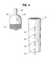
- FIG. 4is a disassembled perspective view of the cap and body of the clamp.
- FIG. 5is a perspective view showing four clamps according to an embodiment of the present invention attached to a common carabiner which is pulled by a tugger.
- FIG. 6is a side view, including hidden lines, of the cylindrical body and cap of the device assembled together.
- FIG. 7is a cross-sectional view taking through line 7 — 7 in FIG. 6 .
- FIG. 8is a side view of a tooth.
- FIG. 9is a top view of the tooth of FIG. 8 .
- Preferred embodiments of the present inventionprovide an apparatus and method for releasably clamping elongated items such as wires or cables.
- Some embodiments of the inventioncan conveniently and securely clamp on the end of a line to be pulled through a path such as a conduit, providing adequate pulling force as needed in industry.
- the clamping devicethat can rapidly and conveniently be used without necessarily requiring an additional tool for the attachment and release steps. Further, some embodiments of the device are durable and reusable.
- a clamping device 10which has a cylinder body 12 .
- the cylinder body 12has a first open end 14 and a second internally threaded open end 16 .
- a number of pivoting teeth 18are arranged in circumferential rings spaced from axially each other.
- the teeth 18project generally inwardly from the cylinder body 12 , and are mounted within slots 17 which penetrate entirely through the walls of the cylinder body 12 .
- the pivoting teeth 18are each retained by a pin 19 to pivot around the pin 19 .
- Slots 17are elongated and the rear or radially outwardmost portion of the pivoting teeth 18 move within the elongation of the slot 17 during pivoting of the respective tooth 18 .
- the rear portion 40 of a tooth 18is seen in FIGS. 8 and 9 .
- the bore 41 in the tooth 18receives the pin 19 .
- the teeth 18will tend to fall to a downward, or radial inwardmost resting position.
- the teeth 18are limited in their downward travel by the contact interference of the rear or radially outward most portion 40 of the tooth 18 with the end of the slot 17 .
- the resting place angleis preferably approximately 15 degrees relative to the plane perpendicular to the cylinder body 12 . However, it will be appreciated that the resting angle could be greater or lesser. It is generally preferred that the resting angle be selected such that insertion of wire W, as shown in FIG. 1 will cause the teeth 18 to pivot in the direction of insertion, such as upward as shown in FIG. 1 .
- the teeth 18may preferably have some degree of sharpening at their tip 42 (see FIGS. 8 and 9 ) so that they tend to dig to some extent into the outer surface of the wire W.
- FIGS. 8 and 9illustrate a teeth 18 having the radially outwardmost portion 40 that interferes with the slot 17 to locate the resting position, and a sharp tip 42 having a tip angle and to provide grip.
- the sharpened tip 42enhances the ability of the teeth 18 to provide a resistant force.
- the tips 42 at the teeth 18may have other suitable features and/or surface treatments for providing a frictional force against the outer surface of the wire W. Because in many instances the gripped end of the wire is simply discarded after the pull, however, any damaging effect on the wire at the location of the teeth 18 is not necessarily an undesirable result.
- the pulling device 10further has a removable cap 20 .
- the cap 20provides connection to a wire rope 22 , which may have a loop or other connector at its end distal from the cap 20 .
- the affixing of the ball 23 to the end of the wire rope 22can be accomplished by process as known in the art.
- the wire rope 22may be provided with a ball 23 , a knob, or some other suitable gripping feature, which is larger than a bore 25 which is provided through the end of the cap 20 and through which the rope 22 passes.
- the wire rope 22is further held to the cap 20 by for example, a pair of set screws 24 which may be opposed from each other and tightened and connected on to the end of the wire rope 22 .
- the set screwsare preferably allen headless type set screws.
- the set screws 24are not required to resist the pulling force, but rather if tightened will serve to prevent rotation about the longitudinal axis of the wire rope relative to the cap 20 .
- the set screws 24can be tightened to prevent the axial rotation of the clamping device about its axis, when desired, for example when retrieving a single line.
- the cap 20has an externally threaded end 26 which mates with the internal threads 16 of the cylinder body 12 .
- the sides of the cap 20 , and the sides of the threaded end 16 of the body 12may be provided with respective opposed flats to facilitate gripping of these two items by wrenches in order to tighten and loosen the cap 20 on to the cylinder body 12 .
- a userbegins with the device 10 configured as shown in FIG. 1 (but without any wire inserted) with the cylinder body 12 fully threaded onto the cap 20 .
- the pulling wire rope 22 at this stageis extending out of the cap 20 and may or may not be attached to a tugging device which will provide motive force for the eventual tugging.
- the end of the wire W to be pulledis then inserted, preferably as far as possible, into the interior of the cylinder body 12 through the end 14 . This causes the teeth 18 to pivot in the direction of the insertion into the condition shown in FIG. 1 .
- FIG. 6also illustrates the open end 14 of the cylinder body 12 having a tapered entrance, which facilitates smooth insertion of the wire W.
- the wire Wcan be cut generally by a tool T such as a conventional wire cutter. This will leave an end of the wire W 1 in a freshly cut and substantially undamaged condition and ready for splicing or connection to another item.
- the cut off end W 2will tend to stay held by the pulling device 10 because of its contact with the pivoting teeth 18 .
- a preferable stepis to unscrew the cap 20 off of the body 12 , and then push the cut end W 2 in the direction shown by the arrow A.
- the unscrewing of the cap 20may be done with hand pressure.
- a toolsuch as a wrench may be needed and is particularly suitable where flats are provided, such as flat 32 on the cylinder body 12 and flat 34 in the cap 20 as shown in FIG. 6 .
- the pushing on the wire end W 2 in direction Amay often be accomplished simply by orienting the cylinder body 12 so that the direction A downward so that the force of gravity on the wire end W 2 will cause the wire end W 2 to fall out.
- hand pressure at the end of W 2may be required to overcome any residual frictional gripping on the wire, and in other instances pushing with a tool or similar steps may be employed to free the wire W 2 .
- the illustrated embodimenthas sixteen pivoting teeth 18 , arranged in four bands of four teeth each.
- This number of teethhas been found preferable for certain sizes of wires and expected pull lengths and pull resisting forces. For example, this number of teeth is suitable for certain applications ranging from number 4 copper wire to 250 mcm copper wire with pulling forces up to 1,000 pounds per wire being pulled.
- different numbers of pivoting teethincluding different numbers of circular bands, and different numbers of radially spaced teeth within a band, may both be advantageously employed.
- the number of teeth employed around a single bandpreferably is even number so that pairs of teeth are directly opposed to each other, but odd numbers of teeth may also be advantageously employed.
- the pivot sweep of the teeth 18will permit a device 10 of a certain size, having a certain diameter of cylinder body 12 , to accommodate at least to some degree a range of sizes of wires W to be pulled.
- different sizes or diameters of wires W to be pulledwill involve the teeth 18 having a different gripping angle during the pulling process.
- the gripping angle for optimum pulling forceis generally approximately 45 degrees between the axis of the tooth and the sidewall of the wire W, however, many embodiments of the invention can perform their function at angles both greater and less than a 45 degrees gripping angle.
- FIG. 5illustrates an exemplary arrangement in which four clamping devices 10 are used.
- the four clamping devices 10are each connected by a respective wire rope 22 to a single loop or carabiner 36 , so that all of the devices 10 are pulled at the same rate.
- this tugging line 34may be attached to a power operated take-up roll by a power-operated device that can provide the pulling force necessary.
- FIG. 5illustrates an example where the clamping devices 10 are staggered so that the diameter of the conduit needs to be only be somewhat larger than the diameter of one of the devices 10 .
- the conduitneed only accommodate the diameter of a single device 10 and the three other wire ropes 22 in the illustrated embodiment.
- the deviceis shown pulling a wire it will be appreciated that other items can be gripped. Also, although the device is useful to pull items through conduit it can also be used to pull items through other paths and/or in other industries.
Landscapes
- Engineering & Computer Science (AREA)
- Mechanical Engineering (AREA)
- Electric Cable Installation (AREA)
- Clamps And Clips (AREA)
Abstract
Description
Claims (21)
Priority Applications (3)
| Application Number | Priority Date | Filing Date | Title |
|---|---|---|---|
| US10/405,083US6883782B2 (en) | 2002-08-30 | 2003-04-02 | Cable clamping apparatus and method |
| US11/068,386US7246789B2 (en) | 2002-08-30 | 2005-03-01 | Cable clamping apparatus and method |
| US11/094,471US7128306B2 (en) | 2002-08-30 | 2005-03-31 | Cable clamping apparatus and method |
Applications Claiming Priority (2)
| Application Number | Priority Date | Filing Date | Title |
|---|---|---|---|
| US40755902P | 2002-08-30 | 2002-08-30 | |
| US10/405,083US6883782B2 (en) | 2002-08-30 | 2003-04-02 | Cable clamping apparatus and method |
Related Child Applications (2)
| Application Number | Title | Priority Date | Filing Date |
|---|---|---|---|
| US11/068,386ContinuationUS7246789B2 (en) | 2002-08-30 | 2005-03-01 | Cable clamping apparatus and method |
| US11/094,471ContinuationUS7128306B2 (en) | 2002-08-30 | 2005-03-31 | Cable clamping apparatus and method |
Publications (2)
| Publication Number | Publication Date |
|---|---|
| US20040041136A1 US20040041136A1 (en) | 2004-03-04 |
| US6883782B2true US6883782B2 (en) | 2005-04-26 |
Family
ID=31981368
Family Applications (3)
| Application Number | Title | Priority Date | Filing Date |
|---|---|---|---|
| US10/405,083Expired - Fee RelatedUS6883782B2 (en) | 2002-08-30 | 2003-04-02 | Cable clamping apparatus and method |
| US11/068,386Expired - LifetimeUS7246789B2 (en) | 2002-08-30 | 2005-03-01 | Cable clamping apparatus and method |
| US11/094,471Expired - LifetimeUS7128306B2 (en) | 2002-08-30 | 2005-03-31 | Cable clamping apparatus and method |
Family Applications After (2)
| Application Number | Title | Priority Date | Filing Date |
|---|---|---|---|
| US11/068,386Expired - LifetimeUS7246789B2 (en) | 2002-08-30 | 2005-03-01 | Cable clamping apparatus and method |
| US11/094,471Expired - LifetimeUS7128306B2 (en) | 2002-08-30 | 2005-03-31 | Cable clamping apparatus and method |
Country Status (1)
| Country | Link |
|---|---|
| US (3) | US6883782B2 (en) |
Cited By (25)
| Publication number | Priority date | Publication date | Assignee | Title |
|---|---|---|---|---|
| US20050150681A1 (en)* | 2003-04-17 | 2005-07-14 | Charlie Sawyer | Glow rods with externally mountable anchoring members and related methods |
| US20050242331A1 (en)* | 2002-08-30 | 2005-11-03 | Ames William M | Cable clamping apparatus and method |
| US20060027795A1 (en)* | 2004-08-05 | 2006-02-09 | James Ernest Crawford | Apparatus and methods for disposing conduits, wires, and the like through structures |
| US7478794B1 (en)* | 2006-09-26 | 2009-01-20 | Rectorseal Corporation | Apparatus and methods for gripping an elongated item |
| US20090224220A1 (en)* | 2008-03-05 | 2009-09-10 | David Jordan | Device for gripping and installing wire |
| US20100258771A1 (en)* | 2009-04-09 | 2010-10-14 | White Christopher L | Wire pull assembly |
| USD630501S1 (en) | 2009-07-23 | 2011-01-11 | Southwire Company | Pulling eye |
| USD635450S1 (en) | 2009-07-23 | 2011-04-05 | Southwire Company | Pulling eye |
| US20110101290A1 (en)* | 2009-03-23 | 2011-05-05 | Carlson John R | Integrated Systems Facilitating Wire and Cable Installations |
| US20120043514A1 (en)* | 2010-08-23 | 2012-02-23 | Billy Pugh Company, Inc. | Push/pull tag line |
| US20120090145A1 (en)* | 2010-10-15 | 2012-04-19 | John Mezzalingua Associates Inc. | Elongate member attachment apparatus and method of use thereof |
| US8757594B2 (en) | 2008-10-23 | 2014-06-24 | Southwire Company, Llc | Pulling jacket for use while installing wires in conduit |
| US9027908B1 (en) | 2011-09-01 | 2015-05-12 | Southwire Company, Llc | Field-installable pulling eye |
| US9537293B2 (en) | 2012-02-29 | 2017-01-03 | Encore Wire Corporation | Wire pulling head apparatus with crimp zone indicators and method of using same |
| US9802785B2 (en) | 2008-01-21 | 2017-10-31 | Southwire Company, Llc | Systems and methods for facilitating wire and cable installations |
| US10003179B2 (en) | 2008-01-21 | 2018-06-19 | Southwire Company, Llc | Integrated systems facilitating wire and cable installations |
| USD842670S1 (en) | 2017-10-30 | 2019-03-12 | Derek M. Rose | Universal cable installation tool |
| US10437002B2 (en) | 2016-11-09 | 2019-10-08 | Derek M. Rose | Universal cable installation tool |
| US10461514B2 (en) | 2017-10-06 | 2019-10-29 | Quick Fitting, Inc. | Cable securing device |
| US11018481B1 (en) | 2020-01-29 | 2021-05-25 | Quick Fitting Holding Company, Llc | Cable securing device |
| US11428295B1 (en) | 2021-07-09 | 2022-08-30 | Quick Fitting Holding Company, Llc | Self-locking cable securing device with cartridge and locking element |
| US11639745B2 (en) | 2021-07-08 | 2023-05-02 | Quick Fitting Holding Company, Llc | Self-locking cable securing device, assembly and method |
| US20230291184A1 (en)* | 2020-08-06 | 2023-09-14 | Mes Bros. B.V. | Coupling device and method for pulling an electrical wire through a conduit |
| USD1029617S1 (en)* | 2021-06-03 | 2024-06-04 | Mianlong Chen | Parallel plane structure for cable railing terminals |
| USD1049828S1 (en)* | 2014-04-28 | 2024-11-05 | Itool Equipment Holding Llc | Connector component for a lanyard assembly for wire-pulling purposes |
Families Citing this family (27)
| Publication number | Priority date | Publication date | Assignee | Title |
|---|---|---|---|---|
| US7186038B2 (en)* | 2003-12-29 | 2007-03-06 | Adc Telecommunications, Inc. | Telecommunications connector protective device |
| GB0600445D0 (en)* | 2006-01-11 | 2006-02-15 | Ocean Cable Technologies Ltd | Cable Gripper |
| EP2076949A1 (en)* | 2006-10-06 | 2009-07-08 | Sharon Wright | Apparatus and method for drawing a cable through an opening |
| DE102007027753B4 (en)* | 2007-06-16 | 2009-06-25 | Faurecia Autositze Gmbh | Traction mechanism, in particular for adjustable vehicle seats |
| US8459611B2 (en)* | 2007-08-30 | 2013-06-11 | Wesco Distribution, Inc. | System for the simultaneous introduction of two items into a conduit |
| US8387954B2 (en)* | 2007-08-30 | 2013-03-05 | Wesco Distribution, Inc. | System for the simultaneous introduction of two items into a conduit |
| US7744287B2 (en)* | 2007-09-05 | 2010-06-29 | Adc Telecommunications, Inc. | Connector enclosure |
| US8385712B2 (en)* | 2008-02-29 | 2013-02-26 | Adc Telecommunications, Inc. | Cable pulling assembly |
| WO2010129785A1 (en) | 2009-05-08 | 2010-11-11 | Adc Telecommunications, Inc. | Cable pulling assembly |
| US8412017B2 (en)* | 2009-05-13 | 2013-04-02 | Adc Telecommunications, Inc. | Cable pulling assembly |
| WO2011066363A2 (en)* | 2009-11-25 | 2011-06-03 | Adc Telecommunications Inc. | Cable pulling assembly |
| US8657259B2 (en)* | 2009-12-14 | 2014-02-25 | James Pagliaroli | Fish tape leader |
| US10379308B2 (en) | 2012-03-19 | 2019-08-13 | Brian D. Coate | Apparatus and method for splicing all-dielectric self-supporting fiber optic cable |
| US9684144B2 (en) | 2012-09-28 | 2017-06-20 | Commscope Technologies Llc | Rapid deployment packaging for optical fiber |
| US8973235B2 (en) | 2012-10-19 | 2015-03-10 | Cerro Wire Llc | Pulling head work station |
| US9874238B2 (en) | 2013-04-24 | 2018-01-23 | Shimano Inc. | Bicycle end cap |
| US20140353561A1 (en)* | 2013-05-31 | 2014-12-04 | Verizon Patent And Licensing Inc. | System and method for guiding a cable |
| ES2547584B1 (en)* | 2014-03-07 | 2016-07-12 | Esteyco S.A.P. | Anchoring means with cable for a horizontal joint, and anchoring procedure with cable for a horizontal joint |
| CN104158108B (en)* | 2014-06-24 | 2017-01-18 | 国家电网公司 | cable pulling device |
| US10281005B2 (en) | 2015-05-29 | 2019-05-07 | Commscope Technologies Llc | Cable pulling assembly |
| KR102350622B1 (en)* | 2016-02-24 | 2022-01-11 | 엘에스전선 주식회사 | Pulling eye for submarine cable, method for installing for the same, and submarine cable having the same |
| US9874712B2 (en)* | 2016-06-09 | 2018-01-23 | Ofs Fitel, Llc | Module for optical fiber installation and storage at customer premises |
| US11038323B1 (en) | 2016-06-17 | 2021-06-15 | Southwire Company, Llc | Pulling grip assembly |
| US20180051826A1 (en)* | 2016-08-22 | 2018-02-22 | Kwon J. PARK | Pipe Pulling Head |
| CN107826872B (en)* | 2017-09-20 | 2019-07-09 | 国家电网公司 | A kind of pipeline cable conveying method with auxiliary supporting structure |
| CN107601141B (en)* | 2017-09-20 | 2019-07-09 | 国家电网公司 | A kind of spiral pipeline cable conveying method |
| CN112436443A (en)* | 2020-11-19 | 2021-03-02 | 中建八局轨道交通建设有限公司 | Auxiliary structure for pulling cable and pulling method thereof |
Citations (13)
| Publication number | Priority date | Publication date | Assignee | Title |
|---|---|---|---|---|
| US524035A (en) | 1894-08-07 | Cork-puller | ||
| US2231919A (en) | 1939-11-03 | 1941-02-18 | Bell Telephone Labor Inc | Grappling device |
| US3727967A (en) | 1971-06-17 | 1973-04-17 | Inst Proiectari Si Cercetari P | Universal overshot |
| US3906619A (en) | 1973-10-04 | 1975-09-23 | Frank E Shaffer | Method for securing cable puller connector to a cable |
| US4368910A (en) | 1980-12-08 | 1983-01-18 | Harvey Hubbell Incorporated | Grip for pulling fiber optic cable and method of inserting the cable into the grip |
| US4453291A (en) | 1982-06-21 | 1984-06-12 | Harvey Hubbell Incorporated | Grip for pulling fiber optic cable |
| US4736978A (en) | 1983-09-06 | 1988-04-12 | Katimex-Cielker Gmbh | Coupling device for inserting cables into cable-protecting pipes |
| US5245730A (en) | 1992-08-12 | 1993-09-21 | Martin Horace J | Rope connector having quick engaging and releasing means |
| US5283930A (en)* | 1993-02-12 | 1994-02-08 | American Cord & Webbing Co., Inc. | Cord clamp with hasp for folded cords and the like |
| US5513555A (en)* | 1994-01-21 | 1996-05-07 | Michael J. Plank | Quick-release cam lock with locking pin |
| US5868060A (en)* | 1994-01-24 | 1999-02-09 | Speed Shore Corp. | Quick-release cam lock |
| US6471268B1 (en) | 1999-04-20 | 2002-10-29 | Peter John Stenstrom | Device for displacing a pipe etc |
| US20040041136A1 (en)* | 2002-08-30 | 2004-03-04 | Ames William Mathew | Cable clamping apparatus and method |
Family Cites Families (1)
| Publication number | Priority date | Publication date | Assignee | Title |
|---|---|---|---|---|
| US2331919A (en)* | 1941-04-02 | 1943-10-19 | Emma C Maynes | Fishing reel |
- 2003
- 2003-04-02USUS10/405,083patent/US6883782B2/ennot_activeExpired - Fee Related
- 2005
- 2005-03-01USUS11/068,386patent/US7246789B2/ennot_activeExpired - Lifetime
- 2005-03-31USUS11/094,471patent/US7128306B2/ennot_activeExpired - Lifetime
Patent Citations (13)
| Publication number | Priority date | Publication date | Assignee | Title |
|---|---|---|---|---|
| US524035A (en) | 1894-08-07 | Cork-puller | ||
| US2231919A (en) | 1939-11-03 | 1941-02-18 | Bell Telephone Labor Inc | Grappling device |
| US3727967A (en) | 1971-06-17 | 1973-04-17 | Inst Proiectari Si Cercetari P | Universal overshot |
| US3906619A (en) | 1973-10-04 | 1975-09-23 | Frank E Shaffer | Method for securing cable puller connector to a cable |
| US4368910A (en) | 1980-12-08 | 1983-01-18 | Harvey Hubbell Incorporated | Grip for pulling fiber optic cable and method of inserting the cable into the grip |
| US4453291A (en) | 1982-06-21 | 1984-06-12 | Harvey Hubbell Incorporated | Grip for pulling fiber optic cable |
| US4736978A (en) | 1983-09-06 | 1988-04-12 | Katimex-Cielker Gmbh | Coupling device for inserting cables into cable-protecting pipes |
| US5245730A (en) | 1992-08-12 | 1993-09-21 | Martin Horace J | Rope connector having quick engaging and releasing means |
| US5283930A (en)* | 1993-02-12 | 1994-02-08 | American Cord & Webbing Co., Inc. | Cord clamp with hasp for folded cords and the like |
| US5513555A (en)* | 1994-01-21 | 1996-05-07 | Michael J. Plank | Quick-release cam lock with locking pin |
| US5868060A (en)* | 1994-01-24 | 1999-02-09 | Speed Shore Corp. | Quick-release cam lock |
| US6471268B1 (en) | 1999-04-20 | 2002-10-29 | Peter John Stenstrom | Device for displacing a pipe etc |
| US20040041136A1 (en)* | 2002-08-30 | 2004-03-04 | Ames William Mathew | Cable clamping apparatus and method |
Cited By (52)
| Publication number | Priority date | Publication date | Assignee | Title |
|---|---|---|---|---|
| US20050242331A1 (en)* | 2002-08-30 | 2005-11-03 | Ames William M | Cable clamping apparatus and method |
| US20060011899A1 (en)* | 2002-08-30 | 2006-01-19 | Bendyco Incorporated | Cable clamping apparatus and method |
| US7128306B2 (en)* | 2002-08-30 | 2006-10-31 | Rectorseal Corporation | Cable clamping apparatus and method |
| US7246789B2 (en)* | 2002-08-30 | 2007-07-24 | Rectorseal Corporation | Cable clamping apparatus and method |
| US20050150681A1 (en)* | 2003-04-17 | 2005-07-14 | Charlie Sawyer | Glow rods with externally mountable anchoring members and related methods |
| US6972377B2 (en)* | 2003-04-17 | 2005-12-06 | Bellsouth Intellectual Property Corporation | Glow rods with externally mountable anchoring members and related methods |
| US20060027795A1 (en)* | 2004-08-05 | 2006-02-09 | James Ernest Crawford | Apparatus and methods for disposing conduits, wires, and the like through structures |
| US7216846B2 (en)* | 2004-08-05 | 2007-05-15 | James Ernest Crawford | Apparatus and methods for disposing conduits, wires, and the like through structures |
| US7478794B1 (en)* | 2006-09-26 | 2009-01-20 | Rectorseal Corporation | Apparatus and methods for gripping an elongated item |
| US20090070966A1 (en)* | 2006-09-26 | 2009-03-19 | Rectorseal Corporation | Apparatus and methods for gripping an elongated item |
| US7934697B2 (en)* | 2006-09-26 | 2011-05-03 | Rectorseal Corporation | Apparatus and methods for gripping an elongated item |
| US9864381B2 (en) | 2007-02-15 | 2018-01-09 | Southwire Company, Llc | Integrated systems facilitating wire and cable installations |
| US10003179B2 (en) | 2008-01-21 | 2018-06-19 | Southwire Company, Llc | Integrated systems facilitating wire and cable installations |
| US9802785B2 (en) | 2008-01-21 | 2017-10-31 | Southwire Company, Llc | Systems and methods for facilitating wire and cable installations |
| US20090224220A1 (en)* | 2008-03-05 | 2009-09-10 | David Jordan | Device for gripping and installing wire |
| US8292267B2 (en) | 2008-03-05 | 2012-10-23 | Southwire Company | Device for gripping and installing wire |
| US8459612B2 (en) | 2008-03-05 | 2013-06-11 | Southwire Company | Device for gripping and installing wire |
| US8757594B2 (en) | 2008-10-23 | 2014-06-24 | Southwire Company, Llc | Pulling jacket for use while installing wires in conduit |
| US10707656B2 (en) | 2009-03-23 | 2020-07-07 | Southwire Company, Llc | Integrated systems facilitating wire and cable installations |
| US11611200B2 (en) | 2009-03-23 | 2023-03-21 | Southwire Company, Llc | Integrated systems facilitating wire and cable installations |
| US20110133141A1 (en)* | 2009-03-23 | 2011-06-09 | Carlson John R | Pulling Eye With Integrated Lug For Electrically Coupling Conductor To Terminating Equipment |
| US11228163B2 (en) | 2009-03-23 | 2022-01-18 | Southwire Company, Llc | Integrated systems facilitating wire and cable installations |
| US10569988B2 (en) | 2009-03-23 | 2020-02-25 | Southwire Company, Llc | Integrated systems facilitating wire and cable installations |
| US20110101290A1 (en)* | 2009-03-23 | 2011-05-05 | Carlson John R | Integrated Systems Facilitating Wire and Cable Installations |
| US8800967B2 (en) | 2009-03-23 | 2014-08-12 | Southwire Company, Llc | Integrated systems facilitating wire and cable installations |
| US8844905B2 (en) | 2009-03-23 | 2014-09-30 | Southwire Company, Llc | Pulling eye with integrated lug for electrically coupling conductor to terminating equipment |
| US20100258771A1 (en)* | 2009-04-09 | 2010-10-14 | White Christopher L | Wire pull assembly |
| US8091866B2 (en)* | 2009-04-09 | 2012-01-10 | Christopher L White | Wire pull assembly |
| USD632165S1 (en)* | 2009-07-23 | 2011-02-08 | Southwire Company | Pulling eye |
| USD635450S1 (en) | 2009-07-23 | 2011-04-05 | Southwire Company | Pulling eye |
| USD686061S1 (en) | 2009-07-23 | 2013-07-16 | Southwire Company | Pulling eye |
| USD630501S1 (en) | 2009-07-23 | 2011-01-11 | Southwire Company | Pulling eye |
| US8469339B2 (en)* | 2010-08-23 | 2013-06-25 | Billy Pugh Company, Inc. | Push/pull tag line |
| US20120043514A1 (en)* | 2010-08-23 | 2012-02-23 | Billy Pugh Company, Inc. | Push/pull tag line |
| US20120090145A1 (en)* | 2010-10-15 | 2012-04-19 | John Mezzalingua Associates Inc. | Elongate member attachment apparatus and method of use thereof |
| US9027908B1 (en) | 2011-09-01 | 2015-05-12 | Southwire Company, Llc | Field-installable pulling eye |
| US10374402B2 (en) | 2012-02-29 | 2019-08-06 | Encore Wire Corporation | Wire pulling head apparatus with crimp zone indicators and method of using same |
| US11670920B2 (en) | 2012-02-29 | 2023-06-06 | Encore Wire Corporation | Wire pulling head apparatus with crimp zone indicators and method of using same |
| US9923345B2 (en) | 2012-02-29 | 2018-03-20 | Encore Wire Corporation | Wire pulling head apparatus with crimp zone indicators and method of using same |
| US11228162B2 (en) | 2012-02-29 | 2022-01-18 | Encore Wire Corporation | Wire pulling head apparatus with crimp zone indicators and method of using same |
| US9537293B2 (en) | 2012-02-29 | 2017-01-03 | Encore Wire Corporation | Wire pulling head apparatus with crimp zone indicators and method of using same |
| USD1049828S1 (en)* | 2014-04-28 | 2024-11-05 | Itool Equipment Holding Llc | Connector component for a lanyard assembly for wire-pulling purposes |
| US10437002B2 (en) | 2016-11-09 | 2019-10-08 | Derek M. Rose | Universal cable installation tool |
| US10461514B2 (en) | 2017-10-06 | 2019-10-29 | Quick Fitting, Inc. | Cable securing device |
| USD842670S1 (en) | 2017-10-30 | 2019-03-12 | Derek M. Rose | Universal cable installation tool |
| US11018481B1 (en) | 2020-01-29 | 2021-05-25 | Quick Fitting Holding Company, Llc | Cable securing device |
| US11705698B2 (en) | 2020-01-29 | 2023-07-18 | Quick Fitting Holding Company, Llc | Cable securing device |
| US20230291184A1 (en)* | 2020-08-06 | 2023-09-14 | Mes Bros. B.V. | Coupling device and method for pulling an electrical wire through a conduit |
| US12308624B2 (en)* | 2020-08-06 | 2025-05-20 | Mes Bros. B.V. | Coupling device and method for pulling an electrical wire through a conduit |
| USD1029617S1 (en)* | 2021-06-03 | 2024-06-04 | Mianlong Chen | Parallel plane structure for cable railing terminals |
| US11639745B2 (en) | 2021-07-08 | 2023-05-02 | Quick Fitting Holding Company, Llc | Self-locking cable securing device, assembly and method |
| US11428295B1 (en) | 2021-07-09 | 2022-08-30 | Quick Fitting Holding Company, Llc | Self-locking cable securing device with cartridge and locking element |
Also Published As
| Publication number | Publication date |
|---|---|
| US7128306B2 (en) | 2006-10-31 |
| US20040041136A1 (en) | 2004-03-04 |
| US7246789B2 (en) | 2007-07-24 |
| US20050242331A1 (en) | 2005-11-03 |
| US20060011899A1 (en) | 2006-01-19 |
Similar Documents
| Publication | Publication Date | Title |
|---|---|---|
| US6883782B2 (en) | Cable clamping apparatus and method | |
| US9027908B1 (en) | Field-installable pulling eye | |
| US11705698B2 (en) | Cable securing device | |
| US4911572A (en) | Cable tie back clamp | |
| US7249540B1 (en) | Connector adapter | |
| KR100521349B1 (en) | Internal pipe pulling device | |
| US5787574A (en) | Method for processing the end of a shielded cable | |
| AU2017251002B2 (en) | Wire gripper and live-wire distributing tool utilizing wire gripper | |
| US5752551A (en) | Wire twisting apparatus | |
| KR102015350B1 (en) | Apparatus for twisting electric wire of replacing easily | |
| CN207509062U (en) | A kind of distribution tool tong | |
| US20010029814A1 (en) | Fiber optic cable ripcord tool and method of use | |
| US11264786B2 (en) | Apparatus for securing together a bundle of conductors | |
| US2380725A (en) | Cable tool | |
| KR100604575B1 (en) | Cable Gripping Device and Cable Traction Device | |
| KR200489056Y1 (en) | Cap for cable installation | |
| AU2020426002B2 (en) | Cable securing device | |
| US6526690B2 (en) | Mount for rigging treble and single-barb fishhooks | |
| US20210288478A1 (en) | J-Hook Device for Untwisting Wire | |
| JP6805403B2 (en) | Tool collet for fixing hand tools to tool lanyards | |
| US7210379B1 (en) | Rigging tool | |
| JPH05316628A (en) | Connecting bracket that connects the cable support line to the cable support | |
| CN210224315U (en) | Cable extrusion molding operation conductor lead wire conversion connector | |
| US20080078087A1 (en) | Stripping device for bundled cable | |
| AU723411B2 (en) | Cable feeding apparatus |
Legal Events
| Date | Code | Title | Description |
|---|---|---|---|
| CC | Certificate of correction | ||
| AS | Assignment | Owner name:BENDYCO INCORPORATED, CALIFORNIA Free format text:ASSIGNMENT OF ASSIGNORS INTEREST;ASSIGNORS:ARNES, WILLIAM MATTHEW;WHEATON, JEREMY DANIEL;REEL/FRAME:016608/0557 Effective date:20050225 | |
| AS | Assignment | Owner name:RECTORSEAL CORPORATION, TEXAS Free format text:ASSIGNMENT OF ASSIGNORS INTEREST;ASSIGNOR:BENDYCO, INCORPORATED;REEL/FRAME:017353/0363 Effective date:20060315 | |
| FPAY | Fee payment | Year of fee payment:4 | |
| FEPP | Fee payment procedure | Free format text:PAT HOLDER NO LONGER CLAIMS SMALL ENTITY STATUS, ENTITY STATUS SET TO UNDISCOUNTED (ORIGINAL EVENT CODE: STOL); ENTITY STATUS OF PATENT OWNER: LARGE ENTITY | |
| SULP | Surcharge for late payment | ||
| FPAY | Fee payment | Year of fee payment:8 | |
| AS | Assignment | Owner name:JPMORGAN CHASE BANK, N.A., AS ADMINISTRATIVE AGENT Free format text:SECURITY INTEREST;ASSIGNOR:THE RECTORSEAL CORPORATION;REEL/FRAME:037411/0005 Effective date:20151211 | |
| AS | Assignment | Owner name:RECTORSEAL, LLC, TEXAS Free format text:CONVERSION, FORMATION;ASSIGNOR:THE RECTORSEAL CORPORATION;REEL/FRAME:040665/0755 Effective date:20161121 | |
| AS | Assignment | Owner name:JPMORGAN CHASE BANK, N.A., AS ADMINISTRATIVE AGENT Free format text:SECURITY INTEREST;ASSIGNOR:RECTORSEAL, LLC FORMERLY KNOWN AS THE RECTORSEAL CORPORATION;REEL/FRAME:040818/0086 Effective date:20161130 | |
| REMI | Maintenance fee reminder mailed | ||
| LAPS | Lapse for failure to pay maintenance fees | ||
| STCH | Information on status: patent discontinuation | Free format text:PATENT EXPIRED DUE TO NONPAYMENT OF MAINTENANCE FEES UNDER 37 CFR 1.362 | |
| FP | Lapsed due to failure to pay maintenance fee | Effective date:20170426 |