US6883627B1 - Engine hood for motor vehicles for the protection of pedestrians - Google Patents
Engine hood for motor vehicles for the protection of pedestriansDownload PDFInfo
- Publication number
- US6883627B1 US6883627B1US09/692,722US69272200AUS6883627B1US 6883627 B1US6883627 B1US 6883627B1US 69272200 AUS69272200 AUS 69272200AUS 6883627 B1US6883627 B1US 6883627B1
- Authority
- US
- United States
- Prior art keywords
- engine hood
- regions
- region
- bearer
- predominantly
- Prior art date
- Legal status (The legal status is an assumption and is not a legal conclusion. Google has not performed a legal analysis and makes no representation as to the accuracy of the status listed.)
- Expired - Fee Related
Links
- 239000011324beadSubstances0.000claimsabstractdescription48
- 239000011257shell materialSubstances0.000claimsdescription66
- 239000000463materialSubstances0.000claimsdescription8
- 230000007935neutral effectEffects0.000claimsdescription3
- 230000000630rising effectEffects0.000claims5
- 230000003014reinforcing effectEffects0.000abstractdescription3
- 239000002184metalSubstances0.000description6
- 239000004033plasticSubstances0.000description6
- 229920003023plasticPolymers0.000description6
- 239000000872bufferSubstances0.000description3
- 241000264877Hippospongia communisSpecies0.000description2
- 208000027418Wounds and injuryDiseases0.000description2
- 239000006096absorbing agentSubstances0.000description2
- 239000002131composite materialSubstances0.000description2
- 238000010276constructionMethods0.000description2
- 230000006378damageEffects0.000description2
- 239000002657fibrous materialSubstances0.000description2
- 208000014674injuryDiseases0.000description2
- 238000012986modificationMethods0.000description2
- 230000004048modificationEffects0.000description2
- 239000002984plastic foamSubstances0.000description2
- 230000035939shockEffects0.000description2
- 238000010521absorption reactionMethods0.000description1
- 230000006978adaptationEffects0.000description1
- 238000005352clarificationMethods0.000description1
- 230000000694effectsEffects0.000description1
- 230000005484gravityEffects0.000description1
- 238000000034methodMethods0.000description1
- 230000035515penetrationEffects0.000description1
- 230000002787reinforcementEffects0.000description1
- 238000012916structural analysisMethods0.000description1
- 238000003466weldingMethods0.000description1
Images


Classifications
- B—PERFORMING OPERATIONS; TRANSPORTING
- B60—VEHICLES IN GENERAL
- B60R—VEHICLES, VEHICLE FITTINGS, OR VEHICLE PARTS, NOT OTHERWISE PROVIDED FOR
- B60R21/00—Arrangements or fittings on vehicles for protecting or preventing injuries to occupants or pedestrians in case of accidents or other traffic risks
- B60R21/34—Protecting non-occupants of a vehicle, e.g. pedestrians
- B60R2021/343—Protecting non-occupants of a vehicle, e.g. pedestrians using deformable body panel, bodywork or components
Definitions
- the inventionrelates to an engine hood for motor vehicles, and more specifically to an engine hood having a deformable head impact zone for the protection of pedestrians in the event of a collision with the motor vehicle.
- U.S. Pat. No. 5,706,908discloses an engine hood having an energy-absorbing impact body under the outer panel.
- the design of the engine hoodis such that the energy generated during impact against components in the engine space is absorbed by virtue of the outer engine hood panel undergoing ideal deformation to absorb the impact energy.
- a disadvantage to be seen hereis that it is always necessary to have an additional impact body and energy absorption takes place mainly due to local plastic deformation.
- Japanese Patent Document 05 155 355discloses an engine hood stiffened by means of regularly arranged reinforcing profiles, in such a way that it undergoes plastic deformation in a controlled manner in the event of a head impact.
- the rigid junction points of the reinforcing profilesare weakened by holes and cutouts in order to reduce rigidity peaks in these regions.
- the impact energyis absorbed solely in the form of local plastic deformation.
- the engine hoodhas a substantially softer behavior in the middle of the hood as compared with the supported edges of the hood.
- An object of the inventionis to provide an engine hood which, in the event of a head impact against any place on the engine hood, always has essentially similar rigidity, in order to implement a uniform deformation behavior over the entire engine hood, taking into account minimal penetration parameters.
- the engine hood according to the inventionhas relatively high flexural strength in its middle region.
- the momentum of the impactis transmitted to the largest part of the engine hood, that is to say almost the entire mass of the engine hood counteracts the impact and thus leads to the desired deceleration.
- the engine hoodbehaves a priori in a substantially more rigid way, since the nearby bearers form a virtually rigid support.
- the engine hoodis designed with lower flexural strength, with the result that the head impact energy is conducted to only a small part of the engine hood. This leads to lower deceleration due to the mass inertia of the hood and therefore compensates for the rigid behavior of the engine hood at the bearers.
- the above-described functioning of the engine hoodaffords the following profile of flexural strengths: next to the bearers, the flexural strength is predominantly lower than or equal to a first value B1; in the middle region of the hood, the flexural strength is predominantly higher than or equal to a second value B2, B2 being greater than B1; and in the intermediate regions, the flexural strength if predominantly higher than the value B1 and lower than the value B2.
- This basic profile of flexural strengthscan be implemented in various design-related ways.
- the flexural strengthmay be adapted by the distribution of the shell thicknesses.
- the sum of all the shell thicknessesis then greater in the middle than at the edges and, in turn, greater at the edges than in the regions directly next to the bearers.
- the inventive flexural strength distributionmay likewise be achieved by varying the distance between the outer shell and inner shell in the region of the head impact zone. A small distance between the shells is then obtained next to the bearers. This value rises along the edges of the hood between the bearers, and the greatest distance is reached in the middle of the engine hood.
- the inner shellsare designed with beads.
- the beadshave flanges which bear against the outer shell and at which the inner shell is connected to the outer shell.
- the inventive flexural strength profileis adopted. Since the beads constitute discrete individual strips, thus making it difficult to calculate the flexural strength of the engine hood, this flexural strength is determined, instead, by means of the inherent rigidities of the beads. This is permissible, because the advantageous embodiment of the engine hood requires a large number of regularly distributed beads.
- the desired flexural strength profileis then achieved by adapting the flexural strength of each individual bead. This is determined at a section perpendicular to the neutral axis of the bead, all the load-bearing shells present in this section being taken into account in the calculation.
- the neutral axis of the beadis a line connecting two junction points where three or more beads converge.
- the flexural strengthmay also be adapted by means of the width of the beads.
- the beads next to the bearersare designed with a very small width. This width has a higher value at the edges of the engine hood between the bearers, and the width of the beads is greatest in the middle of the engine hood.
- the beadsare advantageously designed as hat profiles, the profile flanges being connected to the outer shell.
- the hat profiles of the beads and the convergence of three beads at the junction pointscombine to achieve a uniform support of the outer shell. Rigidity peaks on the engine hood are consequently avoided.
- the average weight per unit area of the engine hoodis obtained by dividing the mass of the engine hood without bearers by the total area of the engine hood.
- a reference surface elementis defined as a circular portion of the hood having a diameter of 25 cm., the approximate size of the contact area of a human head.
- the weight per unit area of a reference surface elementis determined by taking the total mass of all the shells lying below a vertical projection of the reference surface element, and dividing by the area of the reference surface element. The weight per unit area thus obtained for each reference surface element should differ from the average weight per unit area of the engine hood by no more than 20%.
- individual regions of the engine hoodmay also be provided with additional supporting shells arranged between the inner shell and outer shell.
- additional supporting shellssuch as plastic foams or metal honeycombs
- a uniform mass distributionmay be achieved by adapting the density of the material of the supporting shells.
- the material of the supporting shellhas different densities as follows: in the middle of the engine hood predominantly a low density, next to the bearers a predominantly high density and at the edges located between the bearers and between the bearers and the middle of the engine hood a medium density.
- FIG. 1shows an illustration of the head impact zone on the engine hood
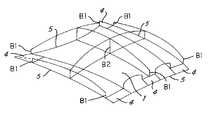
- FIG. 2shows a diagrammatic flexural strength profile over the engine hood
- FIG. 3shows a profile of the shell thicknesses in a cross section through the engine hood
- FIG. 4shows a profile of the shell distances in a cross section through the engine hood
- FIG. 5shows a profile of the bead widths over the cross section of an engine hood
- FIG. 6shows a top view of an engine hood inner shell with beads
- FIG. 7shows a cross-section taken along line 7 — 7 of FIG. 6 ;
- FIG. 8shows a cross-section through an engine hood with an additional supporting shell
- FIG. 9shows a cross section through an engine hood with a homogeneous supporting shell of varying density
- FIG. 10shows a view of the engine hood for determining the uniform mass distribution.
- FIG. 1shows the typical head impact region 2 for an engine hood 1 .
- the front edge 3 of the head impact regionis shifted forward to a greater or lesser extent.
- the bearer regions 4where the engine hood 1 is supported very rigidly relative to the vehicle during the head impact.
- the bearer regions 4coincide with components such as hinges, locks, and stop buffers arranged under the engine hood.
- the general profile of flexural strengths over the engine hood 1is illustrated in FIG. 2 .
- the flexural strengthAdjacent the bearer regions 4 , the flexural strength has approximately the value B1; in the middle region, the flexural strength is predominantly higher than or equal to the value B2; and in the regions between the bearer regions 4 and the middle region, the flexural strength is predominantly higher than the value B1 and lower than the value B2.
- the strength profileis to the greatest possible extent continuous.
- FIGS. 3 to 5show, by means of cross sections through the engine hood, several examples of how the flexural strength profile of the hood may be adapted.
- FIG. 3illustrates an outer shell 6 and an inner shell 7 having a varying thickness profile.
- the inner shell 7is composed of metal sheets of three different thicknesses. This may be achieved by welding together the various sheet-metal thicknesses, as in so-called taylor-welded blanks, or by adhesively bonding individual doubler sheets locally one on the other. In this case, the sheet thickness is the least at the edge and the greatest in the middle of the engine hood.
- a continuous thickness profile without jumpsmay be implemented, both for the inner shell and for the outer shell, by means of a component made of plastic or of composite fiber material.
- the inner shell 8 in FIG. 4is stiffened by means of regular beads 9 which all have the same width.
- the inner shell 8is connected to the outer shell 11 at the upper bead flanges 10 .
- the flexural strengthis adapted by varying the height of the beads 9 : the height 12 is small at the edge of the engine hood, while the height 13 is greatest in the middle of the engine hood.
- the section through the engine hood in FIG. 5shows basically the same makeup as in FIG. 4 .
- the outer shell 14 and inner shell 15are connected via the bead flanges 16 .
- the flexural strengthsare adapted by varying the width of the beads: the bead width is small at the edge of the engine hood, as indicated at 17 , and the bead width is greatest in the middle of the engine hood, as indicated at 18 .
- the flexural strengthmay also be adapted by means of any desired combination of the methods shown in FIGS. 3 , 4 and 5 .
- FIG. 6shows a inner shell 19 for an engine hood in a currently conventional sheet-metal form of construction for motor vehicles, in which the engine hood outer shell (not shown) is typically crimped together with the inner shell 19 and adhesively bonded to the latter.
- the hinge regions 20 , the lock region 21 and the region of the stop buffers 22act as bearers, rigidly supporting the hood relative to the vehicle and thus limiting deflection of the hood.
- plastic deformation regions 23are provided at the location of the shock absorber strut domes. In the event of a head impact in these regions, the deformation regions 23 absorb the energy of the impact and thereby provide a degree of protection from the rigid shock absorber strut.
- junction points 26act as rigid local reinforcements, which should be avoided as far as possible in the head impact region.
- the cross section of bead 24is illustrated by way of example in FIG. 7 .
- This sectionis taken perpendicular to an imaginary axis 25 connecting junction points 26 .
- Inner shell 19is adhesively bonded to the outer shell 28 via the bead flanges 27 .
- the width of the bead 24is obtained from the dimensions of the bead bottom 29 and the height from the dimensions of the bead webs 30 .
- the flexural strength for the bead in this sectioncan be calculated using these dimensions and known structural analysis formulae. The flexural strength thus determined at the locations of the individual beads is used to determine the flexural strength profile of the hood.
- FIG. 8shows a cross section through an engine hood with an additional supporting shell 31 disposed between the outer shell 32 and the inner shell 33 .
- the supporting shell 31fulfills essentially a supporting function, it may be designed as a thin-walled shell, stiffened by means of beads or cups, or else as a homogeneous shell consisting of a material of low specific gravity.
- FIG. 9shows, in cross section, a supporting shell formed of a homogeneous material, such as plastic foam or metal honeycomb, with the density of the material varying over the area of the engine hood.
- the supporting shellis divided into three regions: the supporting shell has a high specific density in the edge region 34 of the engine hood, a medium specific density in the inner region 35 and a low specific density in the middle region 36 of the engine hood.
- This varying density profileallows the engine hood to have an approximately uniform mass distribution over the surface area of the hood, so that any part of the hood that may be impacted by a head will have a nearly identical mass.
- FIG. 10shows how the uniform mass distribution described above is checked for the head impact region 2 of the engine hood 1 .
- a reference surface element 37is defined as a circular portion of the hood having a diameter of 25 cm., the approximate size of the contact area between a human head and the hood.
- the weight per unit area of a reference surface element 37is determined by taking the total mass of all the shells lying below a vertical projection of the reference surface element, and dividing by the area of the reference surface element.
- Reference surfaces 37may be defined at any desired position in the head impact region 2 .
- the weight per unit area of the reference surface elementshould differ from the averaged weight per unit area of the engine hood itself by no more than 20%.
- the average weight per unit area of the engine hoodis obtained by dividing the mass of the engine hood without bearers by the total area of the engine hood.
Landscapes
- Engineering & Computer Science (AREA)
- Mechanical Engineering (AREA)
- Superstructure Of Vehicle (AREA)
Abstract
Description
Claims (15)
Applications Claiming Priority (1)
| Application Number | Priority Date | Filing Date | Title |
|---|---|---|---|
| EP99121009AEP1093980B1 (en) | 1999-10-21 | 1999-10-21 | Bonnet for motor vehicles with pedestrian protection |
Publications (1)
| Publication Number | Publication Date |
|---|---|
| US6883627B1true US6883627B1 (en) | 2005-04-26 |
Family
ID=8239252
Family Applications (1)
| Application Number | Title | Priority Date | Filing Date |
|---|---|---|---|
| US09/692,722Expired - Fee RelatedUS6883627B1 (en) | 1999-10-21 | 2000-10-19 | Engine hood for motor vehicles for the protection of pedestrians |
Country Status (5)
| Country | Link |
|---|---|
| US (1) | US6883627B1 (en) |
| EP (1) | EP1093980B1 (en) |
| JP (1) | JP2001151159A (en) |
| DE (1) | DE59901135D1 (en) |
| ES (1) | ES2175889T3 (en) |
Cited By (32)
| Publication number | Priority date | Publication date | Assignee | Title |
|---|---|---|---|---|
| US20030098192A1 (en)* | 2001-10-05 | 2003-05-29 | Gary Brown | Large vehicle hood or trunk lid bodyshell element |
| US20040182616A1 (en)* | 2003-03-18 | 2004-09-23 | Ford Global Technologies Llc | Motor vehicle hood with pedestrian protection |
| US20050082875A1 (en)* | 2003-09-25 | 2005-04-21 | Koki Ikeda | Vehicle hood structure |
| US20050088016A1 (en)* | 2003-10-27 | 2005-04-28 | Toyota Jidosha Kabushiki Kaisha | Hood structure for vehicle |
| US20050212331A1 (en)* | 2004-03-23 | 2005-09-29 | Nissan Motor Co., Ltd. | Engine hood for automobiles |
| US20060006698A1 (en)* | 2004-07-09 | 2006-01-12 | Honda Motor Co., Ltd. | Automobile hood |
| US20080048471A1 (en)* | 2006-08-28 | 2008-02-28 | Seksaria Dinesh C | Lightweight hybrid material truck hood |
| US20080315626A1 (en)* | 2005-08-30 | 2008-12-25 | Frank Lutter | Passive Protection Device for a Motor Vehicle |
| US20090026807A1 (en)* | 2007-07-24 | 2009-01-29 | Gm Global Technology Operations, Inc. | Energy-Absorbing Vehicle Hood Assembly with Cushion Inner Structure |
| US20090025995A1 (en)* | 2007-07-24 | 2009-01-29 | Gm Global Technology Operations, Inc. | Vehicle Hood With Sandwich Inner Structure |
| US20090026793A1 (en)* | 2007-07-27 | 2009-01-29 | Honda Motor Co., Ltd. | Trunk lid frame structure |
| US20090065277A1 (en)* | 2007-09-11 | 2009-03-12 | Gm Global Technology Operations, Inc. | Vehicle Hood Assembly with Rippled Cushion Support |
| US20100140979A1 (en)* | 2007-03-07 | 2010-06-10 | Alcoa Inc. | Pedestrian safe automotive hood having reinforcing foam |
| US20100194148A1 (en)* | 2007-10-11 | 2010-08-05 | Kabushiki Kaisha Kobe Seiko Sho (Kobe Steel, Ltd.) | Inner panel for vehicle |
| US20100244482A1 (en)* | 2005-09-12 | 2010-09-30 | Montagna John C | Tonneau Cover |
| US20110214932A1 (en)* | 2010-03-05 | 2011-09-08 | Daniel Ralston | Hood pedestrian energy absorber |
| US8424629B2 (en) | 2011-03-09 | 2013-04-23 | Shape Corp. | Vehicle energy absorber for pedestrian's upper leg |
| CN103118924A (en)* | 2010-12-03 | 2013-05-22 | 日产自动车株式会社 | Hood inner panel |
| US20140110971A1 (en)* | 2011-04-26 | 2014-04-24 | Mahindra & Mahindra Limited | Ladder Honeycomb Hood Structure For A Motor Vehicle For Pedestrian Protection |
| JP2015024738A (en)* | 2013-07-26 | 2015-02-05 | ダイハツ工業株式会社 | Hood structure of vehicle |
| US9248866B2 (en)* | 2014-06-13 | 2016-02-02 | Toyota Motor Engineering & Manufacturing North America, Inc. | Hood assembly |
| GB2531643A (en)* | 2014-10-21 | 2016-04-27 | Gm Global Tech Operations | Hood for motor vehicle body |
| US9376145B2 (en) | 2012-10-01 | 2016-06-28 | Kobe Steel, Ltd. | Vehicle hood panel |
| US9415812B2 (en) | 2014-04-09 | 2016-08-16 | Kobe Steel, Ltd. | Vehicle hood |
| US20170158163A1 (en)* | 2015-12-04 | 2017-06-08 | Kabushiki Kaisha Kobe Seiko Sho (Kobe Steel, Ltd.) | Vehicle hood |
| CN107054476A (en)* | 2015-12-04 | 2017-08-18 | 株式会社神户制钢所 | Engine cover for vehicle |
| US10144457B2 (en) | 2016-03-31 | 2018-12-04 | Kobe Steel, Ltd. | Vehicle hood |
| US10155546B2 (en)* | 2016-03-31 | 2018-12-18 | Kobe Steel, Ltd. | Vehicle hood |
| US10207749B2 (en)* | 2014-12-16 | 2019-02-19 | Sabic Global Technologies B.V. | Polymeric engine hood assembly, vehicle front end module, vehicles comprising the same and methods of making the same |
| US10315589B2 (en) | 2017-10-05 | 2019-06-11 | Ford Global Technologies, Llc | Reinforced vehicle component cover |
| US10495024B2 (en) | 2017-10-05 | 2019-12-03 | Ford Global Technologies, Llc | Reinforced vehicle component cover |
| US11685336B1 (en) | 2021-12-20 | 2023-06-27 | Ford Global Technologies, Llc | Vehilce-hood assembly including energy absorbers |
Families Citing this family (20)
| Publication number | Priority date | Publication date | Assignee | Title |
|---|---|---|---|---|
| DE10224423B4 (en)* | 2002-06-01 | 2006-02-16 | Thyssenkrupp Stahl Ag | Sheet-like component for car bodies in shell construction, in particular front flap |
| DE10259591A1 (en)* | 2002-12-19 | 2004-07-15 | Daimlerchrysler Ag | Bonnet with pedestrian protection |
| DE10303994A1 (en)* | 2003-02-01 | 2004-08-19 | Daimlerchrysler Ag | Front hood for a motor vehicle |
| DE10321294A1 (en)* | 2003-05-13 | 2004-12-09 | Daimlerchrysler Ag | Stem of a motor vehicle |
| DE10331066A1 (en)* | 2003-07-09 | 2005-02-17 | Dr.Ing.H.C. F. Porsche Ag | Body part, in particular bonnet, for a motor vehicle |
| FR2873086B1 (en) | 2004-07-16 | 2007-12-14 | Univ Pasteur | MULTILAYER HOOD WITH EXTERNALLY FRANGIBLE SKIN WITH REDUCED AGGRESSIVITY IN THE EVENT OF COLLISION WITH A PIETON |
| JP2006044543A (en)* | 2004-08-06 | 2006-02-16 | Kanto Auto Works Ltd | Automotive hood structure |
| DE102004044550B4 (en)* | 2004-09-15 | 2006-11-30 | Dr. Mirtsch Gmbh | Process for honeycomb-structured, energy-absorbing reinforcing and crumple shell for shell-shaped body parts for the protection of pedestrians |
| FR2875777B1 (en)* | 2004-09-24 | 2008-08-15 | Renault Sas | MOTOR VEHICLE COVER WITH REINFORCED LINING |
| DE102005015057A1 (en)* | 2005-03-31 | 2006-10-19 | Benteler Automobiltechnik Gmbh | Front hood for a motor vehicle |
| DE102005044818A1 (en)* | 2005-09-20 | 2007-04-05 | GM Global Technology Operations, Inc., Detroit | Support frame for automobile engine hood has star pattern support within surrounding peripheral zone |
| JP4719039B2 (en)* | 2006-03-15 | 2011-07-06 | 株式会社神戸製鋼所 | Automotive hood |
| FR2914266B1 (en) | 2007-03-28 | 2010-01-08 | Peugeot Citroen Automobiles Sa | HOOD WITH REINFORCED LINING FOR VEHICLE. |
| JP4905898B2 (en)* | 2007-10-11 | 2012-03-28 | 株式会社神戸製鋼所 | Inner panel for vehicle |
| JP4407755B2 (en) | 2008-02-04 | 2010-02-03 | トヨタ自動車株式会社 | Vehicle hood structure |
| JP4760865B2 (en)* | 2008-06-25 | 2011-08-31 | トヨタ自動車株式会社 | Vehicle hood structure |
| DE102009020087A1 (en)* | 2009-05-06 | 2010-11-11 | Volkswagen Ag | Front flap for motor vehicles |
| DE102009023534B4 (en) | 2009-05-30 | 2021-10-07 | Bayerische Motoren Werke Aktiengesellschaft | Body part with an outer skin and a substructure |
| JP5717509B2 (en)* | 2011-03-31 | 2015-05-13 | 株式会社神戸製鋼所 | Hood panel for vehicle |
| CN114750719B (en)* | 2022-03-26 | 2023-02-03 | 小飞鱼智能科技(广东)有限公司 | Intelligent sharing kart safety protection device |
Citations (8)
| Publication number | Priority date | Publication date | Assignee | Title |
|---|---|---|---|---|
| US5115878A (en)* | 1989-07-26 | 1992-05-26 | Mazda Motor Corporation | Hood structure for a vehicle |
| US5124191A (en)* | 1991-03-11 | 1992-06-23 | Aluminum Company Of America | Structural panel |
| US5155878A (en) | 1991-04-15 | 1992-10-20 | Dellis Edward A | Moldable hand grip |
| JPH05155356A (en) | 1991-12-03 | 1993-06-22 | Toyota Motor Corp | Engine hood structure |
| JPH05155355A (en) | 1991-12-03 | 1993-06-22 | Toyota Motor Corp | Engine hood structure |
| JPH0880873A (en) | 1994-09-14 | 1996-03-26 | Nissan Motor Co Ltd | Car hood |
| US5706908A (en)* | 1994-04-18 | 1998-01-13 | Nissan Motor Co., Ltd. | Front upper structure of automotive vehicle |
| US6179364B1 (en)* | 1998-05-13 | 2001-01-30 | Honda Giken Kogyo Kabushiki Kaisha | Bonnet for automobile |
- 1999
- 1999-10-21ESES99121009Tpatent/ES2175889T3/ennot_activeExpired - Lifetime
- 1999-10-21DEDE59901135Tpatent/DE59901135D1/ennot_activeExpired - Fee Related
- 1999-10-21EPEP99121009Apatent/EP1093980B1/ennot_activeExpired - Lifetime
- 2000
- 2000-10-19USUS09/692,722patent/US6883627B1/ennot_activeExpired - Fee Related
- 2000-10-20JPJP2000320564Apatent/JP2001151159A/enactivePending
Patent Citations (9)
| Publication number | Priority date | Publication date | Assignee | Title |
|---|---|---|---|---|
| US5115878A (en)* | 1989-07-26 | 1992-05-26 | Mazda Motor Corporation | Hood structure for a vehicle |
| US5124191A (en)* | 1991-03-11 | 1992-06-23 | Aluminum Company Of America | Structural panel |
| US5155878A (en) | 1991-04-15 | 1992-10-20 | Dellis Edward A | Moldable hand grip |
| JPH05155356A (en) | 1991-12-03 | 1993-06-22 | Toyota Motor Corp | Engine hood structure |
| JPH05155355A (en) | 1991-12-03 | 1993-06-22 | Toyota Motor Corp | Engine hood structure |
| US5706908A (en)* | 1994-04-18 | 1998-01-13 | Nissan Motor Co., Ltd. | Front upper structure of automotive vehicle |
| US5988305A (en)* | 1994-04-18 | 1999-11-23 | Nissan Motor Co., Ltd. | Front upper structure of automotive vehicle |
| JPH0880873A (en) | 1994-09-14 | 1996-03-26 | Nissan Motor Co Ltd | Car hood |
| US6179364B1 (en)* | 1998-05-13 | 2001-01-30 | Honda Giken Kogyo Kabushiki Kaisha | Bonnet for automobile |
Cited By (53)
| Publication number | Priority date | Publication date | Assignee | Title |
|---|---|---|---|---|
| US20030098192A1 (en)* | 2001-10-05 | 2003-05-29 | Gary Brown | Large vehicle hood or trunk lid bodyshell element |
| US20040182616A1 (en)* | 2003-03-18 | 2004-09-23 | Ford Global Technologies Llc | Motor vehicle hood with pedestrian protection |
| US7467680B2 (en) | 2003-03-18 | 2008-12-23 | Ford Global Technologies, Llc | Motor vehicle hood with pedestrian protection |
| US20050082875A1 (en)* | 2003-09-25 | 2005-04-21 | Koki Ikeda | Vehicle hood structure |
| US7147273B2 (en)* | 2003-09-25 | 2006-12-12 | Toyota Jidosha Kabushiki Kaisha | Vehicle hood structure |
| AU2004212614B2 (en)* | 2003-09-25 | 2007-12-06 | Toyota Jidosha Kabushiki Kaisha | Vehicle hood structure |
| US20050088016A1 (en)* | 2003-10-27 | 2005-04-28 | Toyota Jidosha Kabushiki Kaisha | Hood structure for vehicle |
| US7140673B2 (en)* | 2003-10-27 | 2006-11-28 | Toyota Jidosha Kabushiki Kaisha | Hood structure for vehicle |
| US20050212331A1 (en)* | 2004-03-23 | 2005-09-29 | Nissan Motor Co., Ltd. | Engine hood for automobiles |
| US7390055B2 (en)* | 2004-03-23 | 2008-06-24 | Nissan Motor Co., Ltd. | Engine hood for automobiles |
| US20060006698A1 (en)* | 2004-07-09 | 2006-01-12 | Honda Motor Co., Ltd. | Automobile hood |
| US7114765B2 (en)* | 2004-07-09 | 2006-10-03 | Honda Motor Co., Ltd. | Automobile hood |
| US20080315626A1 (en)* | 2005-08-30 | 2008-12-25 | Frank Lutter | Passive Protection Device for a Motor Vehicle |
| US20100244482A1 (en)* | 2005-09-12 | 2010-09-30 | Montagna John C | Tonneau Cover |
| US20080048471A1 (en)* | 2006-08-28 | 2008-02-28 | Seksaria Dinesh C | Lightweight hybrid material truck hood |
| US20110001338A1 (en)* | 2006-08-28 | 2011-01-06 | Seksaria Dinesh C | Lightweight hybrid material truck hoods |
| US7815249B2 (en)* | 2006-08-28 | 2010-10-19 | Alcoa Inc. | Lightweight hybrid material truck hood |
| US8128159B2 (en)* | 2006-08-28 | 2012-03-06 | Alcoa Inc. | Lightweight hybrid material truck hoods |
| US8052198B2 (en) | 2007-03-07 | 2011-11-08 | Alcoa Inc. | Pedestrian safe automotive hood having reinforcing foam |
| US20100140979A1 (en)* | 2007-03-07 | 2010-06-10 | Alcoa Inc. | Pedestrian safe automotive hood having reinforcing foam |
| US20090026807A1 (en)* | 2007-07-24 | 2009-01-29 | Gm Global Technology Operations, Inc. | Energy-Absorbing Vehicle Hood Assembly with Cushion Inner Structure |
| US20090025995A1 (en)* | 2007-07-24 | 2009-01-29 | Gm Global Technology Operations, Inc. | Vehicle Hood With Sandwich Inner Structure |
| US7735908B2 (en) | 2007-07-24 | 2010-06-15 | Gm Global Technology Operations, Inc. | Vehicle hood with sandwich inner structure |
| US20090026793A1 (en)* | 2007-07-27 | 2009-01-29 | Honda Motor Co., Ltd. | Trunk lid frame structure |
| US7597378B2 (en)* | 2007-07-27 | 2009-10-06 | Honda Motor Co., Ltd. | Trunk lid frame structure |
| US7635157B2 (en) | 2007-09-11 | 2009-12-22 | GM Global Technology Operation, INC | Vehicle hood assembly with rippled cushion support |
| US20090065277A1 (en)* | 2007-09-11 | 2009-03-12 | Gm Global Technology Operations, Inc. | Vehicle Hood Assembly with Rippled Cushion Support |
| US8007036B2 (en) | 2007-10-11 | 2011-08-30 | Kobe Steel, Ltd. | Inner panel for vehicle |
| US20100194148A1 (en)* | 2007-10-11 | 2010-08-05 | Kabushiki Kaisha Kobe Seiko Sho (Kobe Steel, Ltd.) | Inner panel for vehicle |
| US8356857B2 (en) | 2010-03-05 | 2013-01-22 | Shape Corp. | Hood pedestrian energy absorber |
| US20110214932A1 (en)* | 2010-03-05 | 2011-09-08 | Daniel Ralston | Hood pedestrian energy absorber |
| US8740291B2 (en) | 2010-12-03 | 2014-06-03 | Nissan Motor Co., Ltd. | Hood inner panel |
| CN103118924A (en)* | 2010-12-03 | 2013-05-22 | 日产自动车株式会社 | Hood inner panel |
| CN103118924B (en)* | 2010-12-03 | 2015-06-17 | 日产自动车株式会社 | Hood inner panel |
| US8424629B2 (en) | 2011-03-09 | 2013-04-23 | Shape Corp. | Vehicle energy absorber for pedestrian's upper leg |
| US20140110971A1 (en)* | 2011-04-26 | 2014-04-24 | Mahindra & Mahindra Limited | Ladder Honeycomb Hood Structure For A Motor Vehicle For Pedestrian Protection |
| US9283923B2 (en)* | 2011-04-26 | 2016-03-15 | Mahindra And Mahindra Limited | Ladder honeycomb hood structure for a motor vehicle for pedestrian protection |
| US9376145B2 (en) | 2012-10-01 | 2016-06-28 | Kobe Steel, Ltd. | Vehicle hood panel |
| JP2015024738A (en)* | 2013-07-26 | 2015-02-05 | ダイハツ工業株式会社 | Hood structure of vehicle |
| US9415812B2 (en) | 2014-04-09 | 2016-08-16 | Kobe Steel, Ltd. | Vehicle hood |
| US9248866B2 (en)* | 2014-06-13 | 2016-02-02 | Toyota Motor Engineering & Manufacturing North America, Inc. | Hood assembly |
| US20160096552A1 (en)* | 2014-06-13 | 2016-04-07 | Toyota Motor Engineering & Manufacturing North America, Inc. | Hood assembly |
| US9586626B2 (en)* | 2014-06-13 | 2017-03-07 | Toyota Motor Engineering & Manufacturing North America, Inc. | Hood assembly |
| GB2531643A (en)* | 2014-10-21 | 2016-04-27 | Gm Global Tech Operations | Hood for motor vehicle body |
| US9701274B2 (en) | 2014-10-21 | 2017-07-11 | GM Global Technology Operations LLC | Hood for a motor vehicle body |
| US10207749B2 (en)* | 2014-12-16 | 2019-02-19 | Sabic Global Technologies B.V. | Polymeric engine hood assembly, vehicle front end module, vehicles comprising the same and methods of making the same |
| US20170158163A1 (en)* | 2015-12-04 | 2017-06-08 | Kabushiki Kaisha Kobe Seiko Sho (Kobe Steel, Ltd.) | Vehicle hood |
| CN107054476A (en)* | 2015-12-04 | 2017-08-18 | 株式会社神户制钢所 | Engine cover for vehicle |
| US10144457B2 (en) | 2016-03-31 | 2018-12-04 | Kobe Steel, Ltd. | Vehicle hood |
| US10155546B2 (en)* | 2016-03-31 | 2018-12-18 | Kobe Steel, Ltd. | Vehicle hood |
| US10315589B2 (en) | 2017-10-05 | 2019-06-11 | Ford Global Technologies, Llc | Reinforced vehicle component cover |
| US10495024B2 (en) | 2017-10-05 | 2019-12-03 | Ford Global Technologies, Llc | Reinforced vehicle component cover |
| US11685336B1 (en) | 2021-12-20 | 2023-06-27 | Ford Global Technologies, Llc | Vehilce-hood assembly including energy absorbers |
Also Published As
| Publication number | Publication date |
|---|---|
| JP2001151159A (en) | 2001-06-05 |
| ES2175889T3 (en) | 2002-11-16 |
| EP1093980B1 (en) | 2002-04-03 |
| EP1093980A1 (en) | 2001-04-25 |
| DE59901135D1 (en) | 2002-05-08 |
Similar Documents
| Publication | Publication Date | Title |
|---|---|---|
| US6883627B1 (en) | Engine hood for motor vehicles for the protection of pedestrians | |
| KR100666578B1 (en) | Bumper beam for cars | |
| US7533912B2 (en) | Hybrid energy absorber for automobile bumper | |
| KR101754174B1 (en) | Asymmetric energy absorber and method of making and using the same | |
| JP2004359230A (en) | Fender support for automobile | |
| CN101360638A (en) | Energy-absorbing vehicle buffers | |
| JP4787728B2 (en) | Body bumper beam and body shock absorber | |
| RU2686287C1 (en) | Design of the rear area of the vehicle | |
| JP2004509798A (en) | Floating bumper beam system | |
| US20070029840A1 (en) | Energy absorbing vehicle fender | |
| KR20080080108A (en) | Automotive Energy Absorption Fenders | |
| CN101360636A (en) | Energy-absorbing vehicle buffers | |
| JP2008013124A (en) | Energy absorbing member for personal protection | |
| JP3149675B2 (en) | Protection structure for occupants in the upper part of the car body | |
| JP4956081B2 (en) | Body bumper beam and body shock absorber | |
| US6764117B2 (en) | Bumper for a vehicle | |
| JP4473537B2 (en) | Energy absorber for personal protection | |
| JP3109427B2 (en) | Car body superstructure | |
| JP3723289B2 (en) | Guard beam for automobile door | |
| CN214451341U (en) | Front reinforcing plate of engine cover inner plate and automobile | |
| JPH0433654B2 (en) |
Legal Events
| Date | Code | Title | Description |
|---|---|---|---|
| AS | Assignment | Owner name:FORD GLOBAL TECHNOLOGIES, LLC, MICHIGAN Free format text:MERGER;ASSIGNOR:FORD GLOBAL TECHNOLOGIES, INC.;REEL/FRAME:013987/0838 Effective date:20030301 Owner name:FORD GLOBAL TECHNOLOGIES, LLC,MICHIGAN Free format text:MERGER;ASSIGNOR:FORD GLOBAL TECHNOLOGIES, INC.;REEL/FRAME:013987/0838 Effective date:20030301 | |
| AS | Assignment | Owner name:FORD GLOBAL TECHNOLOGIES, LLC, MICHIGAN Free format text:ASSIGNMENT OF ASSIGNORS INTEREST;ASSIGNOR:FORD MOTOR COMPANY;REEL/FRAME:014253/0792 Effective date:20030630 Owner name:FORD MOTOR COMPANY, MICHIGAN Free format text:ASSIGNMENT OF ASSIGNORS INTEREST;ASSIGNORS:STAINES, BRADLEY;VEITH, BETTINA;ROETH, THILO;REEL/FRAME:014254/0341;SIGNING DATES FROM 20001016 TO 20001018 | |
| FPAY | Fee payment | Year of fee payment:4 | |
| REMI | Maintenance fee reminder mailed | ||
| LAPS | Lapse for failure to pay maintenance fees | ||
| STCH | Information on status: patent discontinuation | Free format text:PATENT EXPIRED DUE TO NONPAYMENT OF MAINTENANCE FEES UNDER 37 CFR 1.362 | |
| FP | Lapsed due to failure to pay maintenance fee | Effective date:20130426 |