US6883610B2 - Straddle packer systems - Google Patents
Straddle packer systemsDownload PDFInfo
- Publication number
- US6883610B2 US6883610B2US10/021,085US2108501AUS6883610B2US 6883610 B2US6883610 B2US 6883610B2US 2108501 AUS2108501 AUS 2108501AUS 6883610 B2US6883610 B2US 6883610B2
- Authority
- US
- United States
- Prior art keywords
- pressure
- hydraulic pressure
- hydraulic
- pressure switch
- threshold
- Prior art date
- Legal status (The legal status is an assumption and is not a legal conclusion. Google has not performed a legal analysis and makes no representation as to the accuracy of the status listed.)
- Expired - Lifetime, expires
Links
- 238000011282treatmentMethods0.000claimsabstractdescription36
- 238000007789sealingMethods0.000claimsabstractdescription20
- 238000000034methodMethods0.000claimsabstractdescription10
- 230000003213activating effectEffects0.000claimsabstractdescription3
- 239000012530fluidSubstances0.000claimsdescription30
- 238000005086pumpingMethods0.000claimsdescription19
- 238000000429assemblyMethods0.000claimsdescription9
- 230000000712assemblyEffects0.000claimsdescription8
- 238000004891communicationMethods0.000claimsdescription6
- 230000000717retained effectEffects0.000claimsdescription4
- 230000015572biosynthetic processEffects0.000claimsdescription2
- 238000012856packingMethods0.000claimsdescription2
- 230000003247decreasing effectEffects0.000claims1
- 238000002955isolationMethods0.000abstractdescription7
- 238000013461designMethods0.000description15
- 229920001971elastomerPolymers0.000description15
- 238000010586diagramMethods0.000description5
- 125000006850spacer groupChemical group0.000description5
- 230000007246mechanismEffects0.000description4
- 238000005516engineering processMethods0.000description3
- 230000003628erosive effectEffects0.000description3
- 230000009471actionEffects0.000description2
- 230000008901benefitEffects0.000description2
- 238000011109contaminationMethods0.000description2
- 230000000694effectsEffects0.000description2
- 239000004576sandSubstances0.000description2
- 230000008859changeEffects0.000description1
- 239000000356contaminantSubstances0.000description1
- 238000013016dampingMethods0.000description1
- 230000007423decreaseEffects0.000description1
- 238000006073displacement reactionMethods0.000description1
- 239000000806elastomerSubstances0.000description1
- 238000002637fluid replacement therapyMethods0.000description1
- 230000002706hydrostatic effectEffects0.000description1
- 238000012423maintenanceMethods0.000description1
- 238000004519manufacturing processMethods0.000description1
- 238000012986modificationMethods0.000description1
- 230000004048modificationEffects0.000description1
- 230000008569processEffects0.000description1
- 230000001012protectorEffects0.000description1
- 239000007787solidSubstances0.000description1
- 238000013022ventingMethods0.000description1
Images


Classifications
- E—FIXED CONSTRUCTIONS
- E21—EARTH OR ROCK DRILLING; MINING
- E21B—EARTH OR ROCK DRILLING; OBTAINING OIL, GAS, WATER, SOLUBLE OR MELTABLE MATERIALS OR A SLURRY OF MINERALS FROM WELLS
- E21B33/00—Sealing or packing boreholes or wells
- E21B33/10—Sealing or packing boreholes or wells in the borehole
- E21B33/12—Packers; Plugs
- E21B33/124—Units with longitudinally-spaced plugs for isolating the intermediate space
- E—FIXED CONSTRUCTIONS
- E21—EARTH OR ROCK DRILLING; MINING
- E21B—EARTH OR ROCK DRILLING; OBTAINING OIL, GAS, WATER, SOLUBLE OR MELTABLE MATERIALS OR A SLURRY OF MINERALS FROM WELLS
- E21B43/00—Methods or apparatus for obtaining oil, gas, water, soluble or meltable materials or a slurry of minerals from wells
- E21B43/25—Methods for stimulating production
- E21B43/26—Methods for stimulating production by forming crevices or fractures
Definitions
- straddle packer designsare based primarily on cup technology which has many disadvantages.
- straddle packers of this designare limited with respect to the depth and pressure conditions that they can operate under.
- theyare not suitable for highly deviated or horizontal wells with complex profiles.
- straddle packerstend to be primarily mechanical or a combination of mechanical/hydraulic. Many designs are mechanical interlocking slips or dropped balls to synchronize and control packer operation. These types of devices however, are prone to contamination within the operating environment from contaminants such as sand which can enter the devices and cause the devices to fail.
- the retrievablility of packer toolsis also particularly important.
- the cost of both the tool and/or the time associated with attempting to retrieve a jammed toolare significant.
- there is a continuing need to design tools that minimize the risk of the tool becoming jammed downhole which will result in operator expense from lost time or a lost toolFurthermore, in that traditional devices generally have only one method of retrieval, there is also a need for tools which have a variety of retrieval methods such that if one method of retrieval fails, other retrieval methods are possible.
- a straddle packer systemincludes a pair of hydraulic-set packers. Simultaneous setting and releasing of these packers is controlled by a single hydraulic setting mechanism.
- This assemblywith various lengths of straddle tubing between the pair of hydraulic set packers, is used to straddle sections of well bore perforations to be treated.
- the SPSis connected to the coiled tubing and run to the desired depth.
- the packeris set and sealed automatically by increasing the pumping pressure in the coiled tubing, which above a threshold value, allows fracturing treatments to be performed.
- Setting, releasing the packer, and circulating/reverse-circulating across the packeris controlled by the operator by changing the pressure/pumping rate inside the coiled tubing.
- filters and wiper sealsare used.
- the filters and wiper sealsprevent contamination of the tool with sand or any other fine solids that are pumped through the coiled tubing or present in the well bore during the treatment.
- Technology used in the design of the straddle packercan be further developed into the design of the through-tubing packer.
- a straddle packer and fracturing treatment systemcomprising:
- the pressure switch systemis responsive to a third hydraulic pressure threshold between the first and second hydraulic pressure thresholds for closing the at least one frac valve.
- the first hydraulic pressure thresholdis preferably 1000-1200 psi
- the second hydraulic pressure thresholdis preferably 1700-2500 psi
- the third hydraulic pressure thresholdis preferably 1200-1500 psi.
- control system and pressure switch systeminclude:
- the pressure switch systemfurther comprises a hydraulic channel operatively connected between the first high pressure piston chamber and second low pressure piston chamber, wherein the hydraulic channel is open when the pressure switch is in the open position and/or the control system includes circulation nozzles in fluid communication between the interior and exterior of the system for allowing a circulating fluid to be run from the interior to the exterior of the systems.
- the control systemfurther comprises a check valve assembly in fluid communication with the at least on frac valve, the check valve assembly for enabling a circulating fluid to flow from the exterior to the interior of the system while bypassing the circulation nozzles.
- the systemincludes a power shear assembly operatively and hydraulically connected to the lower seal system for hydraulically pressurizing the lower seal element from the underside of the lower seal system.
- the first high pressure piston chamberfurther comprises a second high volume piston chamber and wherein the first high pressure piston chamber is in hydraulic communication with the second high volume piston chamber when the pressure switch is in the closed position and wherein the second high volume piston chamber is vented to the wellbore above the first sealing element when the pressure switch is in the open position and wherein the first high pressure piston chamber and second high volume piston chamber are sealed from one another when the pressure switch is in the open position.
- the inventionprovides a method of treating a formation with a straddle packer through a wellbore comprising the steps of:
- FIG. 1is a schematic diagram of the straddle packer system in accordance with the invention.
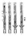
- FIG. 2is a schematic diagram of the straddle packer system in the wash/circulation phase in accordance with the invention
- FIG. 3is a schematic diagram, of the straddle packer system in the setting phase in accordance with the invention.
- FIG. 4is a schematic diagram of the straddle packer system in the treatment phase in accordance with the invention.
- FIG. 5is a schematic diagram of the straddle packer system in the releasing phase in accordance with the invention.
- FIGS. 6A and 6Bare a detailed assembly drawing of the upper packer assembly and control assembly, disposed on the upper mandrel of the tool;
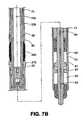
- FIGS. 7A and 7Bare a detailed assembly drawing of the blast joint, lower packer assembly and power shear assembly, disposed on the lower mandrel of the tool;
- FIG. 8is a detailed drawing of the valve section of the straddle packer system in the circulation, setting, treating and releasing phases;
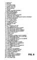
- FIG. 9is a legend identifying reference characters used in FIGS. 1 through 8 .
- FIG. 10is a schematic drawing of the effect of various threshold pressures on the operation of the straddle packer system.
- the straddle packer system (SPS) 100includes five main sub-assemblies including an upper packer assembly 101 , a control assembly 102 , a blast joint 103 , a lower packer assembly 104 and a power shear assembly 105 .
- the SPSallows a zone of interest to be isolated for fracturing treatment.
- the SPSis connected to a coiled tubing string and pushed downhole.
- the upper packer assembly 101 and lower packer assembly 104are set against the well bore or well bore casing to seal the zone of interest by increasing the pumping pressure of fluid circulating through the coiled tubing 200 , SPS and isolated zone 201 (FIG. 3 ).
- a further increase in the pumping pressureopens a valve in the control assembly 102 allowing a fracturing treatment to be applied to the isolated zone 201 (FIG. 4 ).
- the blast joint assembly 103is a section of the SPS of variable length allowing zones of different lengths to be sealed and treated.
- the upper and lower packer assemblies 101 and 104are preferably identical in design as shown in FIG. 6 allowing interchangeability between each assembly for operational and maintenance purposes.
- the upper and lower packer assembliesinclude upper and lower sealing elements 26 a, 26 b (a and b subscripts used for distinguishing between upper and lower packer assembly components typically constructed from a rubber elastomer having sealing and deformation properties suitable for use at high pressures and temperatures.
- the upper sealing element 26 ais installed on a main mandrel 1 and is retained on an upper end of the main mandrel 1 by a top shear ring 3 , upper casing adaptor 4 a and upper piston adaptor 5 a.
- the lower sealing element 26 bis installed on a separate mandrel 1 a and is retained by bottom shear ring 20 lower casing adapter 4 b and lower piston adapter 5 b.
- the upper hydraulic setting mechanismincludes upper piston 7 a, upper piston barrel 6 a and upper barrel adapter assembly 8 a on mandrel 1 .
- the upper piston 7 aattaches to the mandrel 1 with shear pins.
- the lower hydraulic setting mechanismincludes lower piston 7 b, and lower piston barrel 6 b on mandrel 1 a.
- the lower piston 7 battaches to the mandrel 1 a with shear pins.
- High-pressure piston port 33 ajoins the coiled tubing internal volume 30 with the upper high-pressure piston chamber 34 a located between the upper piston 7 a and the upper piston adapter 5 a.
- Low-pressure channel 32 ajoins upper low-pressure piston chamber 35 a on the other side of the upper piston 7 a with the wellbore annulus 31 of the upper packer assembly above seal element 26 a via a shear ring filter 27 a under the top shear ring 3 .
- Lower packer assembly 104has a similar configuration where a lower low-pressure piston channel 32 b extends through the lower packer assembly 104 from the lower low pressure chamber 35 b to the lower side of the bottom shear ring 20 .
- Upper and lower protector sleeves 9 a, 9 bprotect the outside surface of the mandrel 1 from erosion and damage.
- the control assembly 102generally includes a frac sub assembly 10 , a pressure switch housing 12 , a return spring 29 and a pressure switch assembly 15 which operatively interact with each other to open frac ports 38 in the frac sub assembly 10 above a hydraulic threshold pressure to enable fracturing treatment of a zone of interest.
- the frac sub assembly 10includes a poppet seat 37 that provides a sealing surface for a poppet 11 and two large frac ports 38 .
- the poppet 11contains circulation nozzles 36 for enabling a low volume of circulation fluid to flow from inside the mandrel to the annulus during setting. During low Volume circulation, circulation fluid flows through the circulation nozzles 36 and out through ports 36 a at the base of the poppet. The size of the circulation nozzles 36 is restricted to enable pressure build up for setting the SPS and for high pressure frac operations.
- a check valve assembly 56is provided.
- the check valve assemblyincludes a valve 56 a normally biased to a closed position by a valve spring 56 b.
- fluidenters ports 36 a and pushes check valve assembly 56 a to an open position against the biasing pressure of the valve spring 56 b which thereby allows higher volumes of circulating fluid to bypass the circulation nozzles 36 .
- the control assembly 102further includes high 41 and low 40 pressure channels which direct hydraulic fluid through the control assembly for frac valve operation.
- the high-pressure valve channel 41extends between the coiled tubing internal volume 30 of the upper packer assembly 101 (across mandrel filter 28 ) to the lower packer assembly 104 .
- the high pressure valve channel 41also communicates with a first high-pressure chamber 43 and a second pressure chamber 47 via a pressure switch 15 .
- the low-pressure frac valve channel 40is an extension of the low-pressure piston channel 32 and is vented to the wellbore annulus 31 above rubber element 26 Through vent 32 c.
- control assemblyoperates to open a valve in the frac sub assembly to enable fracturing treatment of a zone of interest above a hydraulic threshold pressure.
- control assembly 102functions to:
- sub-systems of springs, pistons and hydraulic channels within the control assemblyinteract to channel hydraulic fluid to different sub-systems depending on the uphole hydraulic pressure.
- These sub-systemsinclude inter aila a high pressure piston 42 , a low pressure piston 46 , a return spring 29 , a switch return spring 14 and associated hydraulic channels and chambers as will be described in greater detail below.
- FIGS. 2 , 3 , 4 , 5 , 8 and 10an overview of the operation of the sub-systems is described with respect to changes in the uphole hydraulic pressure shown as threshold pressures A, B ace, C in FIG. 8 .
- the low pressure pistonmaintains the pressure switch assembly 15 in the open position, thus preventing hydraulic fluid from entering the second high pressure chamber 47 .
- the switch return springovercomes the low pressure piston causing the pressure switch assembly 15 to displace to the closed position
- the high pressure channelis opened and directs high pressure fluid to the second high pressure chamber 47 and simultaneously closes the low pressure channel 32 .
- hydraulic pressureis balanced on both sides of the poppet 11 and the return spring closes the frac valve.
- the SPSis lowered to the desired depth typically on the end of the coiled tubing.
- the circulation/reverse circulation through the coiled tubing and the SPSis possible at all times (FIG. 2 ).
- the top shear ring 3 and the bottom shear ring 20 and the casing adapters 4provide protection for the seal element 26 while running into or pulling out of the well.
- the SPShas built in several safety mechanisms to enable retrieval from the well bore in case of becoming stuck in the hole or if the maximum allowable treatment pressure is exceeded. Consideration is given to both jamming of the upper and lower packer assemblies.
- the force in case of ring 3is compensated via spacer 2 and by the coiled tubing disconnect 2 a.
- the top shear ring 3is supported from the top via spacer 2 by the collar of the coiled tubing disconnect 2 a which is rigidly screwed to the top of the SPS.
- the top shear ring 3can be sheared only by pulling the SPS with the coiled tubing upward.
- the bottom she ring 20is supported from the bottom by the power shear assembly 105 .
- the force applied to this shear ringis neutralized by the action of two pistons in the power shear assembly an upper power shear piston 21 and lower power shear piston 24 which together support the bottom shear ring 20 .
- the pressureis passed through power shear high pressure channel 49 to a first high pressure power shear chamber 50 and a second high pressure power shear chamber 52 through upper and lower power shear piston ports 51 and 53 .
- the pressure differential across the power shear upper piston 21 and power shear lower piston 24supports the bottom shear ring 20 against the combined opposite forces caused by the pressure differential during the treatment across the sealing rubber element 26 and the compressive action of the piston adapter 5 .
- the shear force at which the top shear ring 3 and the bottom shear ring 20 would be shearedis not affected by the pressures experienced by the SPS during treatment.
- the top shear ring 3 and the bottom shear ring 20are easily sheared, which subsequently releases the rubber elements 26 unsetting and freeing the packer.
- the independence of the shear value to shear of the shear rings 3 , 20 from the pressures experienced by the SPS during the treatmentallows an operator to preset the shear at minimum reasonable/required values based only on the strength of the coiled tubing and the depth of the attempted treatment in the well bore.
- the design of the SPSdoes not require the tool to be removed from the well bore even if at some point of the treatment in the well bore, the shear rings 3 , 20 were sheared off.
- an increase in pressure inside the toolresults in the movement of the piston adapter 5 upwards. This movement slides the rubber elements 26 and the sheared top shear ring 3 and the spacer 2 up, until the spacer encounters and is supported on the coiled tubing disconnect 2 a. Since further movement up of the spacer 2 and the top shear ring 3 is not possible, the rubber element 26 is compressed which in turn sets the SPS.
- a further safety feature in the SPSis that, by using a specified number and/or type of shear pins in the pistons 7 a, 7 b the SPS can be set in such that a predetermined maximum pressure inside the SPS and a maximum allowable treatment pressure will not be exceeded. For example, at the moment when the specified maximum operating pressure during treatment with the SPS is exceeded, the shear pins in pistons 7 a, 7 b will shear due to excessive differential pressure across these pistons and the piston adapters 5 a, 5 b release compressed rubber elements 26 a, 26 b, which in turn will unset the SPS.
- This featureprotects the integrity of the SPS and can be also used to protect treated well bore from exposing it to excessive pressures.
- shear pins in pistons 7 a, 7 bare additional shear points, which can be used to free a stuck tool by pulling the tool up with the coiled tubing.
- the flexibility of the rubber elements 26 a, 26 b and the free independent axial movement of casing adapters 6assist in helping to free a stuck SPS if the coiled tubing is manipulated by pulling and/or pushing.
Landscapes
- Life Sciences & Earth Sciences (AREA)
- Engineering & Computer Science (AREA)
- Geology (AREA)
- Mining & Mineral Resources (AREA)
- Physics & Mathematics (AREA)
- Environmental & Geological Engineering (AREA)
- Fluid Mechanics (AREA)
- General Life Sciences & Earth Sciences (AREA)
- Geochemistry & Mineralogy (AREA)
- Consolidation Of Soil By Introduction Of Solidifying Substances Into Soil (AREA)
- Processing Of Solid Wastes (AREA)
- Fluid-Pressure Circuits (AREA)
Abstract
Description
- 1. The SPS is ideally suited for multi zone coiled tubing fracturing but is also suited for any other type of operation requiring zonal isolation or segregated isolation between two points of any bore.
- 2. The SPS allows safe and economical single trip multi zone coiled tubing fracturing in the demanding fracturing operations environment. Also, in contrast to present cup designs of the straddle packers, the SPS does not block circulation across the sealing elements when it is not set.
- 3. The SPS is suitable for use at differential pressures up to 20,000 psi at temperatures up to 800° F. in vertical, highly deviated and horizontal wells or those with complex profiles.
- 4. The SPS provides setting and releasing without the necessity of mandrel movement, but rather automatic setting and releasing controlled by the coiled tubing internal pressure.
- 5. The SPS designed specifically for fracturing with coiled tubing but is not limited to use with coiled tubing. It may be operable even with a limited amount of hydraulic leaking in the SPS hydraulics.
- 6. The SPS provides a better seal with an increase of the treatment pressure.
- 7. The SPS includes frac ports designed to minimize erosion damage to the well bore casing wall and to the frac sub caused by treatment fluid at high pumping rates. The frac ports are hydrodynamically streamlined along the long axis of the packer and generally direct fluid in a downhole direction. This reduces turbulence of the treatment fluid at the frac port and erosion is minimized by not requiring treatment fluids to change direction through 180 degrees as in past systems. Also, hydrodynamic streamlining of the frac ports minimizes the pumping energy losses to the fluid, which results in more efficient and safer fracturing operations.
- 8. The SPS can be applied to but not limited to various sizes of inner bore well diameters including for 2⅜″×4½″, 2⅞″×5½″, 3½″×7″, and 4½″×9⅝″ through tubing/casing applications. The design of the SPS can be modified to meet the requirements of the packer for through tubing applications. This technology be applied to but not limited to casing sizes for 4½″, 5½″, 6⅝, 7″ and 9″.
- 9. The SPS can straddle considerable lengths of well bore because the fluid is discharged at the up-hole seal section. In this configuration the hydrostatic pressure assists by pushing the fluid into perforations, which result in efficient fracturing treatments.
- upper and lower seal systems having resiliently flexible sealing elements hydraulically and operatively connected to one another, the upper and lower packing systems responsive to an increase in hydraulic pressure for setting the sealing elements at a first hydraulic pressure threshold;
- a control system hydraulically and operatively connected between the upper and lower packer systems, the control system responsive to an increase in hydraulic pressure at a second hydraulic pressure threshold higher than the first hydraulic pressure for activating a pressure switch system within the control system for opening at least one frac valve in the control system.
- a pressure switch operatively retained in the control system, the pressure switch having a first high pressure piston and chamber and a second low pressure piston and chamber, the pressure switch operable between a closed and an open position;
- a pressure switch return spring for biasing the pressure switch to a closed position when the hydraulic pressure is below the second hydraulic pressure threshold;
- a return spring for biasing the at least one frac valve to a closed position when the hydraulic pressure is below the second hydraulic pressure threshold and the pressure switch is in the closed position;
- wherein hydraulic pressure at the second hydraulic pressure threshold acting on the first high pressure piston causes the pressure switch to move to the open position.
- a) lowering a system as in
claim 1 downhole to a zone of interest; - b) increasing pumping pressure to the system to the first hydraulic pressure threshold to seal the upper and lower seal assemblies against the well bore;
- c) increasing the pumping pressure to the system to the second hydraulic pressure threshold to open the at least one frac port; and
- d) increasing the pumping pressure to the system above the second hydraulic pressure threshold to apply a fracturing treatment to the zone of interest.
- a) lowering a system as in
- 1. Open the
frac ports 38 as hydraulic pressure rises above a threshold value; - 2. Keep the
frac ports 38 open when the hydraulic pressure drops below the threshold value until a lower threshold pressure is reached, and - 3. Close the
frac ports 38 when the hydraulic pressure drops below the lower threshold pressure.
- 1. Open the
- 1. Moderate pumping rates (typically up to 2 bpm) will result in a pressure inside the SPS of up to approximately 1000 psi, and allow a free circulation across the
circulation nozzles 36 in the poppet11 (FIG.2). Reverse-circulation is not restricted by thecirculation nozzles 36 as a result of thecheck valve assembly 56 incorporated into thepoppet 11. Accordingly, a wash treatment or fluid replacement in the well bore may be undertaken prior to the isolating the chosen length of the well casing. While circulating/reverse-circulating, thefrac ports 38 are closed by the seal between thepoppet 11 and thepoppet seat 37 inside thevalve assembly poppet 11 and thepoppet seat 37 inside thevalve assembly preloaded return spring 29 presses thepoppet 11 against thepoppet seat 37 in thevalve sub 10 at the beginning of the pumping or at low pumping rates through the coiled tubing and the SPS. - 2. As the pumping rate increases, there is a pressure differential created across the circulating
nozzles 36, which in turn increases the pressure inside the coiled tubing and inside the SPS. This increased pressure inside the SPS is passed via high-pressurefrac valve channel 41 to the high-pressurefrac valve chamber 43 and to thesecond pressure chamber 47 behind thepressure switch assembly 15. Thepressure switch assembly 15 with its seals acts as a pressure balanced piston. Because there is no pressure difference across thepressure switch assembly 15, thepreloaded return spring 29 presses thepoppet 11 with thepressure switch assembly 15 against thepoppet seat 37 independently of what pressure is present in the coiled tubing and SPS. As a result, the seal is maintained, thefrac ports 38 remain closed and the pressure build up inside the SPS activates the up-hole and down-hole seal sections. That is, there is a pressure differential across thepistons piston adapters rubber elements rubber elements piston adapters 5a5b.As a result, therubber elements SPS mandrel 1 at approximately 1,500 to 1,800 psi (FIG.3). - 3. The
frac ports 38 are closed until approximately 2000-2,500 psi of pressure inside the SPS is exceeded. At approximately 2,000-2,500 psi, the force created across the high-pressure piston 42 of thepressure switch 15 exceeds the opposite force of the pressureswitch return spring 14. Thepressure switch 15 shifts and, as a result, high-pressure inside thepressure chamber 47 is lowered to that of outside theisolated zone 201. Thepressure switch 15 by damping pressure from thesecond pressure chamber 47 through low-pressurefrac valve channel 40 causes the shift in the position of thepressure switch housing 12 together with thepoppet 11 and opens thefrac ports 38. The pressure differential created across thepressure switch assembly 15 compresses thereturn spring 14. Simultaneously as thepressure switch 15 shifts, the high-pressure is trapped by low-pressure piston 46. The low-pressure piston 46 has a bigger area than the high-pressure piston 42. Thus, pressure in the SPS and in the coiled tubing can drop down below setting pressure of 2000-2,500 psi, as low as 1,000 psi, and thefrac ports 38 will remain open. Thepressure switch 15 with its twopistons frac ports 38 at 2,500 psi and to remain activated until the pressure drops below 1,000 psi. Thus, the SPS is insensitive to the pressure fluctuations during the treatment (FIG.10). After the SPS is set, frac treatment of this section of the well bore can proceed as is known by those skilled in the art. - 4. Releasing the pressure inside the coiled tubing simultaneously decreases the pressure inside the SPS after the packer is set. A drop in pressure results in pressure equalization across the straddle seal element26, i.e. the pressure in the straddle zone equalizes to the rest of the well annulus. The sealing/rubber elements26 are free to come back to the pre-squeezed shape because there is no pressure differential across the
pistons 7a7b.Also because of the pressure equalization across thepressure switch 15 and thepressure switch housing 12, the return springs29 and14 reset thepressure switch 15 and push thepressure switch housing 12 withpoppet 11 towards thepoppet seat 37 and close thefrac ports 38.
Other Features
- 1. Moderate pumping rates (typically up to 2 bpm) will result in a pressure inside the SPS of up to approximately 1000 psi, and allow a free circulation across the
Claims (16)
Priority Applications (1)
| Application Number | Priority Date | Filing Date | Title |
|---|---|---|---|
| US10/021,085US6883610B2 (en) | 2000-12-20 | 2001-12-19 | Straddle packer systems |
Applications Claiming Priority (2)
| Application Number | Priority Date | Filing Date | Title |
|---|---|---|---|
| US25645700P | 2000-12-20 | 2000-12-20 | |
| US10/021,085US6883610B2 (en) | 2000-12-20 | 2001-12-19 | Straddle packer systems |
Publications (2)
| Publication Number | Publication Date |
|---|---|
| US20020162660A1 US20020162660A1 (en) | 2002-11-07 |
| US6883610B2true US6883610B2 (en) | 2005-04-26 |
Family
ID=22972311
Family Applications (1)
| Application Number | Title | Priority Date | Filing Date |
|---|---|---|---|
| US10/021,085Expired - LifetimeUS6883610B2 (en) | 2000-12-20 | 2001-12-19 | Straddle packer systems |
Country Status (2)
| Country | Link |
|---|---|
| US (1) | US6883610B2 (en) |
| CA (1) | CA2365554C (en) |
Cited By (38)
| Publication number | Priority date | Publication date | Assignee | Title |
|---|---|---|---|---|
| US20070056750A1 (en)* | 2005-06-09 | 2007-03-15 | Schlumberger Technology Corporation | Deployable Zonal Isolation System |
| US20070068676A1 (en)* | 2005-09-27 | 2007-03-29 | Smith International, Inc. | Wellbore fluid saver assembly |
| US20080277122A1 (en)* | 2005-03-11 | 2008-11-13 | Bard Martin Tinnen | Apparatus and a Method For Deployment of a Well Intervention Tool String Into a Subsea Well |
| US20090159299A1 (en)* | 2007-12-21 | 2009-06-25 | Robert Kratochvil | Dual-stage valve straddle packer for selective stimulation of wells |
| WO2009093913A1 (en)* | 2008-01-24 | 2009-07-30 | Well Technology As | Device and method for isolating a section of a wellbore |
| US20090242211A1 (en)* | 2008-03-28 | 2009-10-01 | Fagley Iv Walter Stone Thomas | Methods and apparatus for a downhole tool |
| US20090283280A1 (en)* | 2001-11-19 | 2009-11-19 | Halliburton Energy Services, Inc. | Hydraulic open hole packer |
| US20100243270A1 (en)* | 2009-03-25 | 2010-09-30 | Ingram Gary D | Method and apparatus for a packer assembly |
| US20100243254A1 (en)* | 2009-03-25 | 2010-09-30 | Robert Murphy | Method and apparatus for isolating and treating discrete zones within a wellbore |
| US20100319928A1 (en)* | 2009-06-22 | 2010-12-23 | Baker Hughes Incorporated | Through tubing intelligent completion and method |
| US20110000547A1 (en)* | 2009-07-02 | 2011-01-06 | Baker Hughes Incorporated | Tubular valving system and method |
| US20110000679A1 (en)* | 2009-07-02 | 2011-01-06 | Baker Hughes Incorporated | Tubular valve system and method |
| US20110000660A1 (en)* | 2009-07-02 | 2011-01-06 | Baker Hughes Incorporated | Modular valve body and method of making |
| US20110000674A1 (en)* | 2009-07-02 | 2011-01-06 | Baker Hughes Incorporated | Remotely controllable manifold |
| US20110000680A1 (en)* | 2009-07-02 | 2011-01-06 | Baker Hughes Incorporated | Remotely controllable variable flow control configuration and method |
| US20110073323A1 (en)* | 2009-09-29 | 2011-03-31 | Baker Hughes Incorporated | Line retention arrangement and method |
| US20110108285A1 (en)* | 2009-11-06 | 2011-05-12 | Fagley Iv Walter Stone Thomas | Method and apparatus for a wellbore assembly |
| US20110174491A1 (en)* | 2009-07-27 | 2011-07-21 | John Edward Ravensbergen | Bottom hole assembly with ported completion and methods of fracturing therewith |
| US8695716B2 (en) | 2009-07-27 | 2014-04-15 | Baker Hughes Incorporated | Multi-zone fracturing completion |
| US20140374120A1 (en)* | 2013-06-21 | 2014-12-25 | Tam International, Inc. | Downhole Valve for Fluid Energized Packers |
| US8944167B2 (en) | 2009-07-27 | 2015-02-03 | Baker Hughes Incorporated | Multi-zone fracturing completion |
| US8955603B2 (en) | 2010-12-27 | 2015-02-17 | Baker Hughes Incorporated | System and method for positioning a bottom hole assembly in a horizontal well |
| US9163493B2 (en) | 2012-12-28 | 2015-10-20 | Halliburton Energy Services, Inc. | Wellbore servicing assemblies and methods of using the same |
| US9267348B2 (en) | 2010-10-15 | 2016-02-23 | Weatherford Technology Holdings, Llc | Method and apparatus for isolating and treating discrete zones within a wellbore |
| US9494010B2 (en) | 2014-06-30 | 2016-11-15 | Baker Hughes Incorporated | Synchronic dual packer |
| US9580990B2 (en) | 2014-06-30 | 2017-02-28 | Baker Hughes Incorporated | Synchronic dual packer with energized slip joint |
| US9683424B2 (en) | 2015-02-06 | 2017-06-20 | Comitt Well Solutions Us Holding Inc. | Apparatus for injecting a fluid into a geological formation |
| US10030474B2 (en) | 2008-04-29 | 2018-07-24 | Packers Plus Energy Services Inc. | Downhole sub with hydraulically actuable sleeve valve |
| US10053957B2 (en) | 2002-08-21 | 2018-08-21 | Packers Plus Energy Services Inc. | Method and apparatus for wellbore fluid treatment |
| US10119365B2 (en) | 2015-01-26 | 2018-11-06 | Baker Hughes, A Ge Company, Llc | Tubular actuation system and method |
| US10138704B2 (en) | 2014-06-27 | 2018-11-27 | Weatherford Technology Holdings, Llc | Straddle packer system |
| US10900320B2 (en) | 2019-03-01 | 2021-01-26 | Exacta-Frac Energy Services, Inc | Uphole end for a compression-set straddle packer |
| US10900319B2 (en) | 2017-12-14 | 2021-01-26 | Exacta-Frac Energy Services, Inc. | Cased bore straddle packer |
| US10920513B2 (en) | 2016-07-19 | 2021-02-16 | Halliburton Energy Services, Inc. | Composite permanent packer spacer system |
| US11035189B2 (en) | 2019-04-01 | 2021-06-15 | Exacta-Frac Energy Services, Inc. | Compression-set straddle packer with fluid pressure-boosted packer set |
| US11098543B2 (en)* | 2019-08-12 | 2021-08-24 | Exacta-Frac Energy Services, Inc. | Hydraulic pressure converter with modular force multiplier for downhole tools |
| US11168537B2 (en) | 2020-04-06 | 2021-11-09 | Exacta-Frac Energy Services, Inc. | Fluid-pressure-set uphole end for a hybrid straddle packer |
| US11268377B2 (en)* | 2017-10-12 | 2022-03-08 | China University Of Mining And Technology | Measurement-while-drilling method and device for obtaining coal seam gas parameter |
Families Citing this family (24)
| Publication number | Priority date | Publication date | Assignee | Title |
|---|---|---|---|---|
| US7011157B2 (en)* | 2002-10-31 | 2006-03-14 | Schlumberger Technology Corporation | Method and apparatus for cleaning a fractured interval between two packers |
| US7128157B2 (en)* | 2003-07-09 | 2006-10-31 | Weatherford/Lamb, Inc. | Method and apparatus for treating a well |
| US7647980B2 (en)* | 2006-08-29 | 2010-01-19 | Schlumberger Technology Corporation | Drillstring packer assembly |
| CA2670218A1 (en)* | 2009-06-22 | 2010-12-22 | Trican Well Service Ltd. | Method for providing stimulation treatments using burst disks |
| MX366242B (en)* | 2010-01-29 | 2019-07-03 | Schlumberger Tech B V Star | Mechanical tube wave sources and methods of use for liquid filled boreholes. |
| US9841523B2 (en) | 2010-01-29 | 2017-12-12 | Schlumberger Technology Corporation | Tube wave generation |
| CA2749636C (en) | 2010-02-18 | 2014-05-06 | Ncs Oilfield Services Canada Inc. | Downhole tool assembly with debris relief, and method for using same |
| CA2713611C (en)* | 2010-09-03 | 2011-12-06 | Ncs Oilfield Services Canada Inc. | Multi-function isolation tool and method of use |
| US9045953B2 (en)* | 2011-03-14 | 2015-06-02 | Baker Hughes Incorporated | System and method for fracturing a formation and a method of increasing depth of fracturing of a formation |
| CA2798343C (en) | 2012-03-23 | 2017-02-28 | Ncs Oilfield Services Canada Inc. | Downhole isolation and depressurization tool |
| US8931557B2 (en)* | 2012-07-09 | 2015-01-13 | Halliburton Energy Services, Inc. | Wellbore servicing assemblies and methods of using the same |
| US9528353B1 (en)* | 2015-08-27 | 2016-12-27 | William Jani | Wellbore perforating tool |
| CN106481326A (en)* | 2015-09-02 | 2017-03-08 | 中国石油化工股份有限公司 | The no chock pressure difference fracturing strings of self controllable supercharging |
| US10590758B2 (en) | 2015-11-12 | 2020-03-17 | Schlumberger Technology Corporation | Noise reduction for tubewave measurements |
| WO2017119877A1 (en)* | 2016-01-06 | 2017-07-13 | Halliburton Energy Services, Inc. | Downhole hydraulic fracturing tool |
| WO2018004369A1 (en) | 2016-07-01 | 2018-01-04 | Шлюмберже Канада Лимитед | Method and system for locating downhole objects which reflect a hydraulic signal |
| US10119376B2 (en)* | 2016-09-15 | 2018-11-06 | Comitt Well Solutions Us Holding Inc. | Methods and systems for maintaining a pressure differential between pairs of packers |
| CN108999586A (en)* | 2018-08-10 | 2018-12-14 | 中国地震局地壳应力研究所 | Minor diameter rock mass hydrofracturing tests straddle packer |
| CN111963135A (en)* | 2020-09-14 | 2020-11-20 | 中国石油集团渤海钻探工程有限公司 | Throttling-free self-service deblocking two-layer fracturing string and fracturing method thereof |
| US11952858B2 (en)* | 2021-01-15 | 2024-04-09 | Per Angman | Isolation tool and methods of use thereof |
| CN113027408B (en)* | 2021-05-08 | 2022-09-09 | 山东博赛特石油技术有限公司 | Integrated damping switch layered fracturing device and method |
| CN113338841B (en)* | 2021-06-29 | 2022-07-22 | 大庆市天顺和泰石油科技有限公司 | Mechanical packer |
| CN114542011B (en)* | 2022-02-16 | 2023-06-23 | 西南石油大学 | A acidizing ball seat suitable for ultra-deep carbonate gas reservoirs and its application method |
| CN116658116B (en)* | 2023-07-31 | 2024-01-30 | 成都若克石油技术开发有限公司 | Packer for positioning perforations and method of use |
Citations (8)
| Publication number | Priority date | Publication date | Assignee | Title |
|---|---|---|---|---|
| US2738014A (en) | 1954-07-23 | 1956-03-13 | Oil Recovery Corp | Oil well packer construction |
| US2776014A (en)* | 1953-12-14 | 1957-01-01 | Socony Mobil Oil Co Inc | Tool for fracturing earth formations |
| US3382930A (en)* | 1966-03-09 | 1968-05-14 | Keystone Valve Corp | Blast joint |
| US5000265A (en) | 1990-01-23 | 1991-03-19 | Otis Engineering Corporation | Packing assembly for use with reeled tubing and method of operating and removing same |
| US5277253A (en) | 1992-04-03 | 1994-01-11 | Halliburton Company | Hydraulic set casing packer |
| US5295393A (en)* | 1991-07-01 | 1994-03-22 | Schlumberger Technology Corporation | Fracturing method and apparatus |
| US5501281A (en) | 1994-08-26 | 1996-03-26 | Halliburton Company | Torque-resistant, seal setting force-limited, hydraulically settable well packer structure and associated methods |
| US5782306A (en) | 1995-12-14 | 1998-07-21 | Site Oil Tools, Inc. | Open hole straddle system |
- 2001
- 2001-12-19CACA002365554Apatent/CA2365554C/ennot_activeExpired - Lifetime
- 2001-12-19USUS10/021,085patent/US6883610B2/ennot_activeExpired - Lifetime
Patent Citations (8)
| Publication number | Priority date | Publication date | Assignee | Title |
|---|---|---|---|---|
| US2776014A (en)* | 1953-12-14 | 1957-01-01 | Socony Mobil Oil Co Inc | Tool for fracturing earth formations |
| US2738014A (en) | 1954-07-23 | 1956-03-13 | Oil Recovery Corp | Oil well packer construction |
| US3382930A (en)* | 1966-03-09 | 1968-05-14 | Keystone Valve Corp | Blast joint |
| US5000265A (en) | 1990-01-23 | 1991-03-19 | Otis Engineering Corporation | Packing assembly for use with reeled tubing and method of operating and removing same |
| US5295393A (en)* | 1991-07-01 | 1994-03-22 | Schlumberger Technology Corporation | Fracturing method and apparatus |
| US5277253A (en) | 1992-04-03 | 1994-01-11 | Halliburton Company | Hydraulic set casing packer |
| US5501281A (en) | 1994-08-26 | 1996-03-26 | Halliburton Company | Torque-resistant, seal setting force-limited, hydraulically settable well packer structure and associated methods |
| US5782306A (en) | 1995-12-14 | 1998-07-21 | Site Oil Tools, Inc. | Open hole straddle system |
Cited By (65)
| Publication number | Priority date | Publication date | Assignee | Title |
|---|---|---|---|---|
| US9366123B2 (en) | 2001-11-19 | 2016-06-14 | Packers Plus Energy Services Inc. | Method and apparatus for wellbore fluid treatment |
| US9963962B2 (en) | 2001-11-19 | 2018-05-08 | Packers Plus Energy Services Inc. | Method and apparatus for wellbore fluid treatment |
| US10822936B2 (en) | 2001-11-19 | 2020-11-03 | Packers Plus Energy Services Inc. | Method and apparatus for wellbore fluid treatment |
| US20090283280A1 (en)* | 2001-11-19 | 2009-11-19 | Halliburton Energy Services, Inc. | Hydraulic open hole packer |
| US9303501B2 (en) | 2001-11-19 | 2016-04-05 | Packers Plus Energy Services Inc. | Method and apparatus for wellbore fluid treatment |
| US10087734B2 (en) | 2001-11-19 | 2018-10-02 | Packers Plus Energy Services Inc. | Method and apparatus for wellbore fluid treatment |
| US7832472B2 (en) | 2001-11-19 | 2010-11-16 | Halliburton Energy Services, Inc. | Hydraulic open hole packer |
| US10487624B2 (en) | 2002-08-21 | 2019-11-26 | Packers Plus Energy Services Inc. | Method and apparatus for wellbore fluid treatment |
| US10053957B2 (en) | 2002-08-21 | 2018-08-21 | Packers Plus Energy Services Inc. | Method and apparatus for wellbore fluid treatment |
| US20080277122A1 (en)* | 2005-03-11 | 2008-11-13 | Bard Martin Tinnen | Apparatus and a Method For Deployment of a Well Intervention Tool String Into a Subsea Well |
| US7870909B2 (en)* | 2005-06-09 | 2011-01-18 | Schlumberger Technology Corporation | Deployable zonal isolation system |
| US20070056750A1 (en)* | 2005-06-09 | 2007-03-15 | Schlumberger Technology Corporation | Deployable Zonal Isolation System |
| US20070068676A1 (en)* | 2005-09-27 | 2007-03-29 | Smith International, Inc. | Wellbore fluid saver assembly |
| US7401651B2 (en)* | 2005-09-27 | 2008-07-22 | Smith International, Inc. | Wellbore fluid saver assembly |
| US20090159299A1 (en)* | 2007-12-21 | 2009-06-25 | Robert Kratochvil | Dual-stage valve straddle packer for selective stimulation of wells |
| US7789163B2 (en)* | 2007-12-21 | 2010-09-07 | Extreme Energy Solutions, Inc. | Dual-stage valve straddle packer for selective stimulation of wells |
| US20100307774A1 (en)* | 2008-01-24 | 2010-12-09 | Tinnen Baard Martin | Device and method for isolating a section of a wellbore |
| WO2009093913A1 (en)* | 2008-01-24 | 2009-07-30 | Well Technology As | Device and method for isolating a section of a wellbore |
| US20110030960A1 (en)* | 2008-03-28 | 2011-02-10 | Fagley Iv Walter Stone Thomas | Methods and apparatus for a downhole tool |
| US7836962B2 (en) | 2008-03-28 | 2010-11-23 | Weatherford/Lamb, Inc. | Methods and apparatus for a downhole tool |
| US20090242211A1 (en)* | 2008-03-28 | 2009-10-01 | Fagley Iv Walter Stone Thomas | Methods and apparatus for a downhole tool |
| US8316943B2 (en) | 2008-03-28 | 2012-11-27 | Weatherford/Lamb, Inc. | Methods and apparatus for a downhole tool |
| US10704362B2 (en) | 2008-04-29 | 2020-07-07 | Packers Plus Energy Services Inc. | Downhole sub with hydraulically actuable sleeve valve |
| US10030474B2 (en) | 2008-04-29 | 2018-07-24 | Packers Plus Energy Services Inc. | Downhole sub with hydraulically actuable sleeve valve |
| US9291044B2 (en) | 2009-03-25 | 2016-03-22 | Weatherford Technology Holdings, Llc | Method and apparatus for isolating and treating discrete zones within a wellbore |
| US20100243254A1 (en)* | 2009-03-25 | 2010-09-30 | Robert Murphy | Method and apparatus for isolating and treating discrete zones within a wellbore |
| US8186446B2 (en) | 2009-03-25 | 2012-05-29 | Weatherford/Lamb, Inc. | Method and apparatus for a packer assembly |
| US20100243270A1 (en)* | 2009-03-25 | 2010-09-30 | Ingram Gary D | Method and apparatus for a packer assembly |
| US20100319928A1 (en)* | 2009-06-22 | 2010-12-23 | Baker Hughes Incorporated | Through tubing intelligent completion and method |
| US20110000679A1 (en)* | 2009-07-02 | 2011-01-06 | Baker Hughes Incorporated | Tubular valve system and method |
| US20110000547A1 (en)* | 2009-07-02 | 2011-01-06 | Baker Hughes Incorporated | Tubular valving system and method |
| US20110000660A1 (en)* | 2009-07-02 | 2011-01-06 | Baker Hughes Incorporated | Modular valve body and method of making |
| US20110000674A1 (en)* | 2009-07-02 | 2011-01-06 | Baker Hughes Incorporated | Remotely controllable manifold |
| US20110000680A1 (en)* | 2009-07-02 | 2011-01-06 | Baker Hughes Incorporated | Remotely controllable variable flow control configuration and method |
| US8267180B2 (en) | 2009-07-02 | 2012-09-18 | Baker Hughes Incorporated | Remotely controllable variable flow control configuration and method |
| US8281865B2 (en) | 2009-07-02 | 2012-10-09 | Baker Hughes Incorporated | Tubular valve system and method |
| US8944167B2 (en) | 2009-07-27 | 2015-02-03 | Baker Hughes Incorporated | Multi-zone fracturing completion |
| US20110174491A1 (en)* | 2009-07-27 | 2011-07-21 | John Edward Ravensbergen | Bottom hole assembly with ported completion and methods of fracturing therewith |
| US8695716B2 (en) | 2009-07-27 | 2014-04-15 | Baker Hughes Incorporated | Multi-zone fracturing completion |
| US8613321B2 (en)* | 2009-07-27 | 2013-12-24 | Baker Hughes Incorporated | Bottom hole assembly with ported completion and methods of fracturing therewith |
| US20110073323A1 (en)* | 2009-09-29 | 2011-03-31 | Baker Hughes Incorporated | Line retention arrangement and method |
| US10030481B2 (en) | 2009-11-06 | 2018-07-24 | Weatherford Technology Holdings, Llc | Method and apparatus for a wellbore assembly |
| US10753179B2 (en) | 2009-11-06 | 2020-08-25 | Weatherford Technology Holdings, Llc | Wellbore assembly with an accumulator system for actuating a setting tool |
| US20110108285A1 (en)* | 2009-11-06 | 2011-05-12 | Fagley Iv Walter Stone Thomas | Method and apparatus for a wellbore assembly |
| US8931569B2 (en) | 2009-11-06 | 2015-01-13 | Weatherford/Lamb, Inc. | Method and apparatus for a wellbore assembly |
| US9267348B2 (en) | 2010-10-15 | 2016-02-23 | Weatherford Technology Holdings, Llc | Method and apparatus for isolating and treating discrete zones within a wellbore |
| US8955603B2 (en) | 2010-12-27 | 2015-02-17 | Baker Hughes Incorporated | System and method for positioning a bottom hole assembly in a horizontal well |
| US9163493B2 (en) | 2012-12-28 | 2015-10-20 | Halliburton Energy Services, Inc. | Wellbore servicing assemblies and methods of using the same |
| US9644451B2 (en)* | 2013-06-21 | 2017-05-09 | Tam International, Inc. | Downhole valve for fluid energized packers |
| US20140374120A1 (en)* | 2013-06-21 | 2014-12-25 | Tam International, Inc. | Downhole Valve for Fluid Energized Packers |
| US10138704B2 (en) | 2014-06-27 | 2018-11-27 | Weatherford Technology Holdings, Llc | Straddle packer system |
| US9580990B2 (en) | 2014-06-30 | 2017-02-28 | Baker Hughes Incorporated | Synchronic dual packer with energized slip joint |
| US9494010B2 (en) | 2014-06-30 | 2016-11-15 | Baker Hughes Incorporated | Synchronic dual packer |
| US10119365B2 (en) | 2015-01-26 | 2018-11-06 | Baker Hughes, A Ge Company, Llc | Tubular actuation system and method |
| US9683424B2 (en) | 2015-02-06 | 2017-06-20 | Comitt Well Solutions Us Holding Inc. | Apparatus for injecting a fluid into a geological formation |
| US10920513B2 (en) | 2016-07-19 | 2021-02-16 | Halliburton Energy Services, Inc. | Composite permanent packer spacer system |
| US11268377B2 (en)* | 2017-10-12 | 2022-03-08 | China University Of Mining And Technology | Measurement-while-drilling method and device for obtaining coal seam gas parameter |
| US10900319B2 (en) | 2017-12-14 | 2021-01-26 | Exacta-Frac Energy Services, Inc. | Cased bore straddle packer |
| US11454085B2 (en) | 2017-12-14 | 2022-09-27 | Exacta-Frac Energy Services, Inc. | Cased bore straddle packer |
| US10900320B2 (en) | 2019-03-01 | 2021-01-26 | Exacta-Frac Energy Services, Inc | Uphole end for a compression-set straddle packer |
| US11293255B2 (en) | 2019-03-01 | 2022-04-05 | Exacta-Frac Energy Services, Inc. | Uphole end for a compression-set straddle packer |
| US11643901B2 (en) | 2019-03-01 | 2023-05-09 | Exacta-Frac Energy Services, Inc. | Uphole end for a compression-set straddle packer |
| US11035189B2 (en) | 2019-04-01 | 2021-06-15 | Exacta-Frac Energy Services, Inc. | Compression-set straddle packer with fluid pressure-boosted packer set |
| US11098543B2 (en)* | 2019-08-12 | 2021-08-24 | Exacta-Frac Energy Services, Inc. | Hydraulic pressure converter with modular force multiplier for downhole tools |
| US11168537B2 (en) | 2020-04-06 | 2021-11-09 | Exacta-Frac Energy Services, Inc. | Fluid-pressure-set uphole end for a hybrid straddle packer |
Also Published As
| Publication number | Publication date |
|---|---|
| US20020162660A1 (en) | 2002-11-07 |
| CA2365554A1 (en) | 2002-06-20 |
| CA2365554C (en) | 2005-08-02 |
Similar Documents
| Publication | Publication Date | Title |
|---|---|---|
| US6883610B2 (en) | Straddle packer systems | |
| US9976384B2 (en) | Toe sleeve isolation system for cemented casing in borehole | |
| US6474419B2 (en) | Packer with equalizing valve and method of use | |
| US7025146B2 (en) | Alternative packer setting method | |
| US5782306A (en) | Open hole straddle system | |
| EP1437480B1 (en) | High expansion non-elastomeric straddle tool | |
| US7896091B2 (en) | Convertible seal | |
| US5947204A (en) | Production fluid control device and method for oil and/or gas wells | |
| US5279370A (en) | Mechanical cementing packer collar | |
| US8720561B2 (en) | Sliding stage cementing tool and method | |
| AU636883B2 (en) | Method and apparatus for treatment of subterranean well bores | |
| EP2960429B1 (en) | Straddle packer system | |
| US9664015B2 (en) | Fracturing system and method | |
| US4969524A (en) | Well completion assembly | |
| US20100051276A1 (en) | Stage cementing tool | |
| US5615741A (en) | Packer inflation system | |
| GB2388855A (en) | Cementing a production string | |
| US20180320478A1 (en) | Method and apparatus for wellbore fluid treatment | |
| WO2021242910A2 (en) | Stage cementing system | |
| CA2342657C (en) | Zero drill completion and production system | |
| RU2777032C1 (en) | Set of equipment for multi-stage hydraulic fracturing | |
| CA2846755A1 (en) | Fracturing system and method |
Legal Events
| Date | Code | Title | Description |
|---|---|---|---|
| AS | Assignment | Owner name:PROGESSIVE TECHNOLOGY, ALBERTA Free format text:ASSIGNMENT OF ASSIGNORS INTEREST;ASSIGNOR:DEPIAK, KAROL;REEL/FRAME:013710/0096 Effective date:20021219 Owner name:PROGRESSIVE TECHNOLOGY, CANADA Free format text:ASSIGNMENT OF ASSIGNORS INTEREST;ASSIGNOR:JAGERT, FRED;REEL/FRAME:013710/0348 Effective date:20021217 | |
| AS | Assignment | Owner name:DEPIAK INDUSTRIAL TECHNOLOGY CORPORATION, CANADA Free format text:ASSIGNMENT OF ASSIGNORS INTEREST;ASSIGNOR:PROGRESSIVE TECHNOLOGY LTD.;REEL/FRAME:015208/0855 Effective date:20040227 | |
| STCF | Information on status: patent grant | Free format text:PATENTED CASE | |
| FPAY | Fee payment | Year of fee payment:4 | |
| FEPP | Fee payment procedure | Free format text:PAT HOLDER NO LONGER CLAIMS SMALL ENTITY STATUS, ENTITY STATUS SET TO UNDISCOUNTED (ORIGINAL EVENT CODE: STOL); ENTITY STATUS OF PATENT OWNER: LARGE ENTITY | |
| REFU | Refund | Free format text:REFUND - PAYMENT OF MAINTENANCE FEE, 8TH YR, SMALL ENTITY (ORIGINAL EVENT CODE: R2552); ENTITY STATUS OF PATENT OWNER: LARGE ENTITY | |
| FPAY | Fee payment | Year of fee payment:8 | |
| FPAY | Fee payment | Year of fee payment:12 |