US6883065B1 - System and method for a redundant communication channel via storage area network back-end - Google Patents
System and method for a redundant communication channel via storage area network back-endDownload PDFInfo
- Publication number
- US6883065B1 US6883065B1US10/183,979US18397902AUS6883065B1US 6883065 B1US6883065 B1US 6883065B1US 18397902 AUS18397902 AUS 18397902AUS 6883065 B1US6883065 B1US 6883065B1
- Authority
- US
- United States
- Prior art keywords
- controllers
- storage
- controller
- slave
- master controller
- Prior art date
- Legal status (The legal status is an assumption and is not a legal conclusion. Google has not performed a legal analysis and makes no representation as to the accuracy of the status listed.)
- Expired - Lifetime, expires
Links
Images


Classifications
- G—PHYSICS
- G06—COMPUTING OR CALCULATING; COUNTING
- G06F—ELECTRIC DIGITAL DATA PROCESSING
- G06F11/00—Error detection; Error correction; Monitoring
- G06F11/07—Responding to the occurrence of a fault, e.g. fault tolerance
- G06F11/16—Error detection or correction of the data by redundancy in hardware
- G06F11/20—Error detection or correction of the data by redundancy in hardware using active fault-masking, e.g. by switching out faulty elements or by switching in spare elements
- G06F11/2053—Error detection or correction of the data by redundancy in hardware using active fault-masking, e.g. by switching out faulty elements or by switching in spare elements where persistent mass storage functionality or persistent mass storage control functionality is redundant
- G06F11/2089—Redundant storage control functionality
- G06F11/2092—Techniques of failing over between control units
- G—PHYSICS
- G06—COMPUTING OR CALCULATING; COUNTING
- G06F—ELECTRIC DIGITAL DATA PROCESSING
- G06F11/00—Error detection; Error correction; Monitoring
- G06F11/07—Responding to the occurrence of a fault, e.g. fault tolerance
- G06F11/0703—Error or fault processing not based on redundancy, i.e. by taking additional measures to deal with the error or fault not making use of redundancy in operation, in hardware, or in data representation
- G06F11/0706—Error or fault processing not based on redundancy, i.e. by taking additional measures to deal with the error or fault not making use of redundancy in operation, in hardware, or in data representation the processing taking place on a specific hardware platform or in a specific software environment
- G06F11/0727—Error or fault processing not based on redundancy, i.e. by taking additional measures to deal with the error or fault not making use of redundancy in operation, in hardware, or in data representation the processing taking place on a specific hardware platform or in a specific software environment in a storage system, e.g. in a DASD or network based storage system
- G—PHYSICS
- G06—COMPUTING OR CALCULATING; COUNTING
- G06F—ELECTRIC DIGITAL DATA PROCESSING
- G06F11/00—Error detection; Error correction; Monitoring
- G06F11/07—Responding to the occurrence of a fault, e.g. fault tolerance
- G06F11/0703—Error or fault processing not based on redundancy, i.e. by taking additional measures to deal with the error or fault not making use of redundancy in operation, in hardware, or in data representation
- G06F11/0766—Error or fault reporting or storing
- G06F11/0784—Routing of error reports, e.g. with a specific transmission path or data flow
- G—PHYSICS
- G06—COMPUTING OR CALCULATING; COUNTING
- G06F—ELECTRIC DIGITAL DATA PROCESSING
- G06F12/00—Accessing, addressing or allocating within memory systems or architectures
- G06F12/02—Addressing or allocation; Relocation
- G06F12/08—Addressing or allocation; Relocation in hierarchically structured memory systems, e.g. virtual memory systems
- G06F12/0802—Addressing of a memory level in which the access to the desired data or data block requires associative addressing means, e.g. caches
- G06F12/0866—Addressing of a memory level in which the access to the desired data or data block requires associative addressing means, e.g. caches for peripheral storage systems, e.g. disk cache
- G—PHYSICS
- G06—COMPUTING OR CALCULATING; COUNTING
- G06F—ELECTRIC DIGITAL DATA PROCESSING
- G06F3/00—Input arrangements for transferring data to be processed into a form capable of being handled by the computer; Output arrangements for transferring data from processing unit to output unit, e.g. interface arrangements
- G06F3/06—Digital input from, or digital output to, record carriers, e.g. RAID, emulated record carriers or networked record carriers
- G06F3/0601—Interfaces specially adapted for storage systems
- G06F3/0602—Interfaces specially adapted for storage systems specifically adapted to achieve a particular effect
- G06F3/0614—Improving the reliability of storage systems
- G06F3/0617—Improving the reliability of storage systems in relation to availability
- G—PHYSICS
- G06—COMPUTING OR CALCULATING; COUNTING
- G06F—ELECTRIC DIGITAL DATA PROCESSING
- G06F3/00—Input arrangements for transferring data to be processed into a form capable of being handled by the computer; Output arrangements for transferring data from processing unit to output unit, e.g. interface arrangements
- G06F3/06—Digital input from, or digital output to, record carriers, e.g. RAID, emulated record carriers or networked record carriers
- G06F3/0601—Interfaces specially adapted for storage systems
- G06F3/0628—Interfaces specially adapted for storage systems making use of a particular technique
- G06F3/0662—Virtualisation aspects
- G06F3/0664—Virtualisation aspects at device level, e.g. emulation of a storage device or system
- G—PHYSICS
- G06—COMPUTING OR CALCULATING; COUNTING
- G06F—ELECTRIC DIGITAL DATA PROCESSING
- G06F3/00—Input arrangements for transferring data to be processed into a form capable of being handled by the computer; Output arrangements for transferring data from processing unit to output unit, e.g. interface arrangements
- G06F3/06—Digital input from, or digital output to, record carriers, e.g. RAID, emulated record carriers or networked record carriers
- G06F3/0601—Interfaces specially adapted for storage systems
- G06F3/0668—Interfaces specially adapted for storage systems adopting a particular infrastructure
- G06F3/067—Distributed or networked storage systems, e.g. storage area networks [SAN], network attached storage [NAS]
- G—PHYSICS
- G06—COMPUTING OR CALCULATING; COUNTING
- G06F—ELECTRIC DIGITAL DATA PROCESSING
- G06F3/00—Input arrangements for transferring data to be processed into a form capable of being handled by the computer; Output arrangements for transferring data from processing unit to output unit, e.g. interface arrangements
- G06F3/06—Digital input from, or digital output to, record carriers, e.g. RAID, emulated record carriers or networked record carriers
- G06F3/0601—Interfaces specially adapted for storage systems
- G06F3/0668—Interfaces specially adapted for storage systems adopting a particular infrastructure
- G06F3/0671—In-line storage system
- G06F3/0683—Plurality of storage devices
- G06F3/0689—Disk arrays, e.g. RAID, JBOD
- G—PHYSICS
- G06—COMPUTING OR CALCULATING; COUNTING
- G06F—ELECTRIC DIGITAL DATA PROCESSING
- G06F11/00—Error detection; Error correction; Monitoring
- G06F11/07—Responding to the occurrence of a fault, e.g. fault tolerance
- G06F11/0703—Error or fault processing not based on redundancy, i.e. by taking additional measures to deal with the error or fault not making use of redundancy in operation, in hardware, or in data representation
- G06F11/0751—Error or fault detection not based on redundancy
- G06F11/0754—Error or fault detection not based on redundancy by exceeding limits
- G06F11/0757—Error or fault detection not based on redundancy by exceeding limits by exceeding a time limit, i.e. time-out, e.g. watchdogs
- G—PHYSICS
- G06—COMPUTING OR CALCULATING; COUNTING
- G06F—ELECTRIC DIGITAL DATA PROCESSING
- G06F11/00—Error detection; Error correction; Monitoring
- G06F11/07—Responding to the occurrence of a fault, e.g. fault tolerance
- G06F11/16—Error detection or correction of the data by redundancy in hardware
- G06F11/20—Error detection or correction of the data by redundancy in hardware using active fault-masking, e.g. by switching out faulty elements or by switching in spare elements
- G06F11/2002—Error detection or correction of the data by redundancy in hardware using active fault-masking, e.g. by switching out faulty elements or by switching in spare elements where interconnections or communication control functionality are redundant
- G06F11/2007—Error detection or correction of the data by redundancy in hardware using active fault-masking, e.g. by switching out faulty elements or by switching in spare elements where interconnections or communication control functionality are redundant using redundant communication media
- G06F11/201—Error detection or correction of the data by redundancy in hardware using active fault-masking, e.g. by switching out faulty elements or by switching in spare elements where interconnections or communication control functionality are redundant using redundant communication media between storage system components
- G—PHYSICS
- G06—COMPUTING OR CALCULATING; COUNTING
- G06F—ELECTRIC DIGITAL DATA PROCESSING
- G06F3/00—Input arrangements for transferring data to be processed into a form capable of being handled by the computer; Output arrangements for transferring data from processing unit to output unit, e.g. interface arrangements
- G06F3/06—Digital input from, or digital output to, record carriers, e.g. RAID, emulated record carriers or networked record carriers
- G06F3/0601—Interfaces specially adapted for storage systems
Definitions
- the present inventionrelates to storage area networks and, more particularly, to fault-tolerant storage area networks.
- Mass storagehas typically been implemented as hard disk drives connected to an internal bus, or backplane, of an individual workstation.
- SCSI or IDE drivesthat range from hundreds of megabytes to gigabytes, are attached to controller interface cards or chips that plug into a workstation's bus.
- This type of local mass storageis accessed by way of the workstation's operating system which recognizes the filesystem commands generated by user applications and translates them into low-level bus protocols for accessing the hardware of the local mass storage.
- These hardware accessestypically are performed in predetermined block sizes and are, therefore, often called block protocols.
- NASNetworked attached storage
- SANsstorage area networks
- NASnetworked attached storage
- SANsstorage area networks
- NASnetworked attached storage
- SANsstorage area networks
- the storage deviceconnects directly to the network medium and does not require an intermediate server to provide access to the storage.
- a separate network of storage devicesforms storage space that is allocated to different workstations and this separate network is itself connected to the network medium which connects the different workstations.
- the MAGNITUDE®SANaggregates physical drives into a centralized “virtualized” storage pool and has the ability to stripe across and utilize all available space in a centralized storage pool. From this pool, a user carves out storage into “virtualized disks” and assigns that storage to whichever workstation that needs it. Within the SAN, the workstations see the MAGNITUDE®SAN's virtual disks as Logical Unit Numbers (LUNs). Within MAGNITUDE®SAN, virtualization refers to different levels of logical constructs rather than to physical storage devices (e.g. SCSI hard disk drives).
- LUNsLogical Unit Numbers
- the basic MAGNITUDE®SAN systemincludes up to 32 SCSI hard drives on plural SCSI busses, although an expansion box is available to double the system size.
- a configurable number of virtual disks and virtual RAID devices (or arrays)are arranged across these drives.
- a virtual diskcan comprise one or more of the virtual RAID devices.
- Each of these virtual disksare presented to one or more remote workstations on a Fibre Channel network as an addressable disk drive that appears and acts like local storage (i.e., an available local drive).
- RAID arraysare well-known and according to the typical rules defining various RAID levels, data is “striped” across more than one physical drive.
- a “stripe”refers to the number of disk sectors written to each physical drive before data is written to the next drive in the RAID array.
- Each driveis divided into stripes with data being written to the first stripe in each of the drives and then to the second stripe in each drive, until the drives have reached capacity.
- stripescan be mirrored or can have parity stripes interspersed among the data stripes in different patterns.
- RAID deviceOne recent extension to conventional RAID is that more than one similar RAID device can be arrayed across the same physical disks.
- each physical driveis identically partitioned into multiple partitions irrespective of the available capacity.
- One RAID deviceis arrayed across each of similarly numbered partitions among the physical drives; another RAID device can be arrayed across other similarly numbered partitions among the same physical drives.
- the rules and techniques for striping and mirroringremain the same, the difference being that the partitions are considered as the boundaries of a RAID device rather than the physical drives themselves.
- RAID devicesare “virtualized” arrays as well.
- the selected RAID levelmay specify that two data stripes will occur and then the third stripe will be a parity stripe. In a traditional RAID array, this would mean that three physical hard drives are used.
- the “virtualized” RAID devicecan use all the physical devices (e.g., 30) having sufficient capacity to stripe the data and parity irrespective of the selected RAID level. The striping occurs according to the selected RAID level but is not dependent on the particular physical arrangement of the drives.
- a sizeis specified.
- the specified sizeis divided by the number of available physical drives to determine the maximum amount of space needed on each physical drive for the virtualized disk. Those physical drives that have sufficient capacity are made part of a virtualized RAID device. If a physical drive does not have the required capacity, then that physical drive is not included in the virtualized RAID device.
- the MAGNITUDE®SANis responsible for presenting the available virtualized disks as addressable devices on the Fibre Channel fabric. As a result, the remote workstations need only generate a typical block-level command (e.g., SCSI-3 command) to access blocks on an available logical drive.
- the MAGNITUDE®SANreceives this conventional protocol request and converts it into a virtual request packet (VRP) for internal processing.
- VRPvirtual request packet
- the MAGNITUDE®SANinternally unencapsulates, parses and processes a VRP message utilizing translation tables in order to eventually generate SCSI commands to access multiple SCSI devices.
- the MAGNITUDE®SANfirst translates the data request within the VRP message to a request involving the particular virtualized disk that corresponds to that target drive for that requester (e.g., Fibre Channel device #7 requests access to their E: drive which corresponds to virtual disk 71 ).
- the MAGNITUDE®SANthen translates the identified virtualized disk data request into a request for the specified data from a particular virtualized RAID device on which the virtualized disk is arrayed (e.g., virtualized RAID device 37 corresponds to virtualized disk 71 ); and another translation then takes place to convert the data request into appropriate sector requests from individual, physical SCSI hard drives that make up the particular virtualized RAID device (e.g., virtualized RAID device 37 is comprised of physical SCSI drives 1 , 3 , 5 , 7 , 15 , 16 , 8 , 19 , 24 , 26 , and 30 ; and the requested data is within sectors striped on physical SCSI drives 18 , 19 , 24 and 26 ).
- the MAGNITUDE®SANenforces access controls at the virtualized disk level. Individual virtualized disks can be assigned to a specific workstation to allow the workstation and its storage to be isolated from another workstation and its storage.
- MAGNITUDE®SANthere is a single controller that performs the many levels of translations needed to permit receiving a request involving a virtualized drive and actually performing data accesses to multiple physical devices.
- RAIDprovides some failure protection for the data, fail-over or fail-safe behavior is not implemented at the system level as the controller is a single point of failure.
- embodiments of the present inventionwhich provide virtualized storage via a SAN and include plural controllers and communication paths to allow for fail-safe and fail-over operation.
- the plural controllersare loosely-coupled to provide n-way redundancy and have plural, independent channels for communicating with one another.
- respective portions from each of the back-end physical disk drives within the SANare used as one of these alternative communication channels to pass messages between controllers.
- Such an alternative communications channelprovides even further redundancy and robustness in the system.
- One aspect of the present inventionrelates to a storage area network that includes more than one loosely-coupled storage controllers arranged in a redundant configuration so as to provide, to a plurality of servers, access to virtualized storage.
- one of the storage controllersoperates as a master controller and the other storage controller or controllers operate as slave controllers.
- the storage area networkalso includes means for communicating among the storage controllers on an alternative communications channel.
- Another aspect of the present inventionrelates to a storage area network that includes plural, loosely-coupled storage controllers that are arranged in a redundant configuration to provide, to a plurality of servers, access to virtualized storage, wherein one of the storage controllers operates as a master controller and the other storage controller or controllers operate as slave controllers.
- the storage area networkalso includes a communications channel coupled to each of the controllers for communicating among the controllers.
- the communications channelitself, includes a memory device that is accessible by all of the storage controllers and is configured to store one or more messages between the master controller and the slave controllers.
- a further aspect of the present inventionrelates to a method for providing a back-end message channel within a storage area network comprising plural, loosely-coupled redundant controllers that are arranged to include a master controller and one or more slave controllers.
- a storage portion on each of a plurality of physical disk drives which are coupled to a respective back-end of each controlleris allocated for storage.
- the messageis written to each of the storage portions by the first slave controller; and when the master controller has a second message to forward to a second slave controller it is written to each of the storage portions by the master controller.
- FIG. 1illustrates an exemplary fibre channel storage area network (SAN);
- SANfibre channel storage area network
- FIG. 2illustrates an exemplary storage controller in accordance with an embodiment of the present invention
- FIG. 3illustrates and exemplary configuration and control board (CCB) in accordance with an embodiment of the present invention that is useful in the storage controller of FIG. 2 ;
- CCAconfiguration and control board
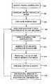
- FIG. 4depicts an exemplary logical flow diagram of a method for configuring plural loosely-coupled storage controllers in accordance with an embodiment of the present invention
- FIG. 5illustrates an exemplary virtual controller group (VCG) in accordance with an embodiment of the present invention
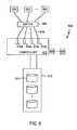
- FIG. 6illustrates an exemplary single controller able to move interface attached target in accordance with an embodiment of the present invention
- FIG. 7illustrates an exemplary SAN that includes redundant front-end connections, redundant controllers, and redundant back-end connections in accordance with an embodiment of the present invention.
- FIGS. 8A-8Cillustrate an exemplary scheme for cache mirroring in accordance with an embodiment of the present invention
- FIG. 9Aillustrates a VCG controller table in accordance with an embodiment of the present invention
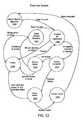
- FIG. 9Billustrates the VCG controllers arranged in a heartbeat tree in accordance with an embodiment of the present invention
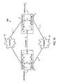
- FIG. 10illustrates a schematic view of the connections between controllers of a VCG in accordance with an embodiment of the present invention
- FIG. 11illustrates an exemplary layout of the reserved area in accordance with an embodiment of the present invention.
- FIG. 12depicts an exemplary state diagram of the master controller election process in accordance with an embodiment of the present invention.
- FIG. 1depicts an exemplary storage area network environment 100 .
- Embodiments of the present inventioncan provide conventional functionality and operation within this environment 100 .
- a number of individual disk drives 110 a - 110 dare connected together to form a storage subsystem 108 .
- This storage subsystem 108is connected via fibre channel media 106 and protocols to different back-end interfaces 116 of a controller 102 .
- the disk storage subsystem connections as depicted in FIG. 1are schematic in nature.
- the actual physical connection topology of the different disk drives 110 a - 110 d to the controller 102is not explicitly depicted in FIG. 1 , as numerous different topologies are recognized to be functionally equivalent.
- One exemplary topologymay be to have four fibre channel loops, each loop having plural hard drives and each loop connected to a different interface 116 of the controller 116 .
- the exemplary network environment 100is implemented using fibre channel; however, the use of other present and future-developed networking technologies providing similar functionality are also contemplated.
- a number of servers 120 - 124are connected to various front-end interfaces 118 of the controller 102 . These connections also utilize fibre channel media 104 to provide various connection topologies between the servers 120 - 124 and the controller 102 .
- the fibre channel media 104can include one or more switches having respective output ports connected to a front-end controller interface 118 and input ports connected to individual servers 120 - 124 or loops of individual servers.
- the controller 102is responsible for presenting storage space to the servers 120 - 124 by directing and controlling access to the disk storage subsystem 108 . This access is not dependent on the underlying physical arrangement and structure of the disk drives 110 a - 110 d ; but, rather, is provided in a virtual (or logical) manner so as to simplify maintenance and management of the storage space made available to the servers 120 - 124 .
- the controller 102presents to each server 120 - 124 respective logical disk drives which can be accessed as if they were physical disk drives connected to the server.
- the servers 120 - 124send data access requests (e.g., read, write, copy, etc.) to the controller 102 directed to a particular logical disk drive and the controller 102 translates the request into commands that access data on the physical drives 110 a - 110 d .
- data access requestse.g., read, write, copy, etc.
- the controller 102also arranges any retrieved data and provides it back to the requesting server 120 - 124 .
- the creation and modification of the storage configuration implemented by the controller 102is accomplished via a workstation 112 .
- the workstation 112connects to the controller 102 via a network connection 104 , such as Ethernet, and interfaces with a storage configuration routine that executes within the controller 102 .
- the storage configuration routinefor example, can be presented via a web server and a user can configure the controller 102 using a web browser on workstation 112 .
- the storage configuration routinecan be a standalone application that communicates with the workstation 112 via TELNET or possibly a proprietary client application.
- a usersuch as a system manager or administrator can define the storage space (and its configuration) that is allocated to each of the servers 120 - 124 .
- a userinterfaces with the storage configuration routine to specify that a new disk is needed; this new disk is a logical, or virtual, disk rather than a physical disk.
- the userassigns this new disk a logical unit number (LUN) associated with the particular server 122 and specifies the capacity of the virtual disk (e.g., 2 Gigabytes).
- LUNlogical unit number
- the useralso specifies which interface 118 will appear to have the virtual disk connected to it.
- the userspecifies the RAID level for the new virtual disk so as to provide some assurance of data availability.
- the RAID levelcan specify striping arrangements such as stripe levels, parity stripes, data stripe size, and even mirroring levels.
- the controller 102determines, and maintains a table that reflects, which sections of the physical drives 110 a - 110 d are used to construct the new virtual disk.
- the controller 102maintains this table information for all the virtual disks that are defined and services data requests from the servers 120 - 124 using this information.
- Each of these virtual disksare, in general, said to be “owned” by the controller 102 and, more particular, are “owned” by the respective interface 118 associated with it.
- fibre channelallows automatic retries when a request times out; uses acknowledgment signals to track the completion of a request; allows automatic path discovery (for example, between the controller 102 and the disk drives 110 a - 110 d ); and allows devices newly added to a medium to be announced and discovered by the other devices on that medium.
- the fibre channel protocolalso utilizes the concept of a “target”. A target is a uniquely identified endpoint for a communication request.
- a fibre channel devicewhen a fibre channel device initiates a request, it will specify a target for that request using the unique target identifier.
- the most simple exampleis a target having a one-to-one correspondence to a physical device such as a disk drive or a workstation.
- a single physical devicecan have multiple ports (logical or physical) and each of these ports can be a distinct target.
- WWNworldwide names
- the WWNis a configurable hardware identifier associated with a fibre channel interface.
- the controller 102provides a different target identifier for each virtual disk that it owns. Accordingly, the table information which implements the storage configuration for a controller 102 includes the following relationships:
- the servers 120 - 124are able to determine which interface 118 to send a particular request to (based on the target identifier).
- the controller 102receives a data request on an interface 118 and, through a process of multiple translations using the configuration information, accesses the appropriate physical drives 110 a - 110 d to satisfy the request.
- FIG. 2provides a more detailed view of an embodiment of a SAN controller 201 .
- the controller 201comprises three major processors—the front-end processor 212 , the back-end processor 208 , and the configuration and control board (CCB) 202 .
- NVRAM 228or other functionally equivalent storage, that is accessible by the front-end 212 and back-end 208 processors to retain a copy of the storage configuration information.
- the front-end processor 212is coupled via a bus 224 to plural fibre channel host bus adapters (HBAs) 220 a - 220 c and executes firmware code to perform its operations.
- the bus 224is a PCI bus and the HBAs 220 a - 220 c are Qlogic® Fibre Channel interface boards.
- Each HBA 220 a - 220 cconnects with one or more of the servers 120 - 124 .
- This side of the controller 102is referred to as the “front-end” or the “host end” which makes the HBAs 220 a - 220 c “host interfaces”.
- the front-end processor 212also includes memory 210 having a section that caches incoming and outgoing commands and data, and another section of memory 210 that stores the front-end processor's firmware. Incoming disk access requests are received via the host interfaces 220 a - 220 c . The front-end processor 212 uses the configuration information in NVRAM 228 to determine which blocks of the virtual disk the access request relates to and then passes this information to the back-end processor 208 .
- the front-end processor 212 and back-end processor 208are connected via a bus 216 , such as a PCI bus.
- the back-end processor 208is coupled via a bus 226 to plural fibre channel host bus adapters (HBAs) 222 a - 222 c and executes its own firmware code to perform its operations.
- the bus 226is a PCI bus.
- HBA 222 a - 222 cconnects with one or more of the physical disks 110 a - 110 d ;
- a HBAis synonymous with a host adapter board (HAB) which reflects terminology used by some vendors.
- HBAhost adapter board
- the back-end processor 208also includes memory 206 having a section that caches incoming and outgoing commands and data; another section of the memory 206 stores the back-end processor's firmware.
- the back-end processor 208will receive from the front-end processor 212 information about a virtual disk access request and generate the actual, physical disk access commands to access the various blocks of the physical disk drives 110 a - 110 d which correspond to the requested blocks of the virtual disk access request.
- the CCB 202is connected to both the front-end 212 and back-end 208 processors, respectively, by busses 214 and 218 which, for example, can be PCI busses.
- busses 214 and 218which, for example, can be PCI busses.
- One alternative to the separate busses 214 - 218 depicted in FIG. 2is a single bus that connects all three components 202 , 208 and 212 .
- the CCB 208includes a number of executable routines that allow monitoring of the health of the different controller components, collecting statistics regarding the storage system 108 , reporting the status of the controller 201 and the storage subsystem 108 to the workstation 112 , performing automatic scripts such as backing-up, copying or mirroring data within the storage system 108 , and allow a user to configure the storage space owned by the controller 201 .
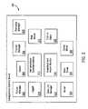
- FIG. 3depicts a more detailed view of exemplary executable applications or routines that run on the CCB 202 according to one embodiment of the present invention.
- the actual hardware of a CCB 202is not depicted in FIG. 3 but will typically comprise a network interface (such as an i82559 Ethernet Controller), a processor (such as an Intel i960), memory (e.g. RAM, Flash RAM, NVRAM), timer circuitry, and interface circuitry for communicating with the front-end 212 and back-end 208 processors over busses 214 and 218 .
- the CCB 202includes management functionality similar to that available from conventional SAN controllers.
- the CCB 202includes an interface for receiving configuration instructions and performing all the complex steps needed for allocating and provisioning storage space accordingly.
- the functions of the CCB 202can include, for example, configuring and controlling RAID devices, configuring and managing server connections, maintaining system event logs, monitoring environmental and power conditions, recording operation statistics, providing notification of failures, and performing diagnostics.
- the CCB 202also includes an executable kernel that works with the front-end 212 and back-end 208 processors to provide control of a SAN (e.g., SAN 500 of FIG. 5 ) during operation.
- a SANe.g., SAN 500 of FIG. 5
- processors 208 , 212typically resident on a processor board and providing data I/O, permit detection of failures of any physical disk drives 110 a - 110 d and identification and substitution of a hot spare.
- the processor boardindicates to the CCB 202 that there is a problem and/or identifies a hot spare, the CCB 202 can perform its functions of logging, notification and reconfiguration as appropriate.
- the CCB 202works with the processor board to provide link and path discovery to determine a) if a complete, working communications channel exists between an front-end HBA 220 a - 220 c and another connected endpoint; b) if a complete working communications channel exists between each back-end HBA 222 a - 222 c and physical disk drives 110 a - 110 d ; and c) if an end-to-end channel exists between the front-end and the back-end processors.
- a complete, working communications channelexists between an front-end HBA 220 a - 220 c and another connected endpoint
- an end-to-end channelexists between the front-end and the back-end processors.
- the operation of the CCB 202is controlled by the kernel 322 .
- This kernel 322provides the operating environment in which the other applications and routines in the CCB 202 will function. As described later, a controller 102 can operate in one of two modes (i.e., a master controller mode and a slave controller mode). Based on which mode the controller 201 is operating in, the kernel 322 determines which routines and applications can execute and which ones are disabled.
- the CCB 202includes a network protocol stack 320 such as a TCP/IP network protocol stack. This stack allows the CCB 202 to communicate over a network in addition to any connections involving fibre channel protocols.
- the CCB 202also includes a web server 310 that provides an interface to a user to configure the SAN. The user will typically connect to the web server 310 via a workstation coupled to the TCP/IP network and then define the virtual disks that are presented on the SAN's front-end. Logging of the controller's ongoing operations is provided by a logger 314 that locally stores log information or can send messages indicating critical log events to external personnel. If more than one controller is working together, the logger 314 in one controller can forward log messages to another controller's logger which, in turn, can consolidate all the, messages and send them to a user's workstation connected to the TCP/IP network.
- a network protocol stack 320such as a TCP/IP network protocol stack. This stack allows the CCB 202 to communicate
- a failure manager 302that is responsible to handle a detected failure or, if unable to handle the failure, forward the failure notification to another failure manager in another controller that can handle the failure.
- the failure manager 302works closely with the resource manager 308 .
- the resource manager 308determines what configuration changes must occur in response to the detected failure.
- the resource manager 308then ensures that these configuration changes are shared with every controller that may be operating in a cooperative, fault-tolerant arrangement.
- the elector 304executes to perform an election process among all cooperatively operating controllers to identify a “master” controller and, thus, provides means for cooperatively determining which of the devices will operate as the master device.
- the election processensures that a master controller is chosen and that only one master controller is chosen. It is on the CCB 202 of this master controller that the resource manager 308 runs. As a result, contention among plural controllers 201 is avoided by limiting the generation of any configuration changes to only a single controller 201 .
- Embodiments of the present inventionpermit portions of the physical hard drives to be utilized for message passing and configuration storage involving any controllers connected to those hard drives. Access and use of these reserved areas of the hard drives are controlled by a channel manager application 306 that operates to permit a controller 201 to read and write data to the reserved areas.
- the CCB 202 of controller 201also includes a communications manager that allows reading and writing of data via the front-end fibre channel links; this manager is the data link manager (DLM) 316 .
- a shim driver 324is included in embodiments of the present invention to allow the data link manager 316 to use some of the features of the TCP/IP stack 320 .
- the CCB 202also includes heartbeat and health monitors 318 (HAH). Although using “heartbeats” to detect the continuing operation of a connected device is a common practice, embodiments of the present invention include heartbeats that involve intra-controller operations as well as inter-controller operations.
- a cache mirror manager 326is also a helpful routine that can be used to improve-performance of disk access operations.
- the cache which is managed by the cache mirror manager 326is typically the front-end write cache that stores data to be written to a virtual disk (and eventually to the physical disk drives). Instead of forcing every routine shown in FIG. 3 to be designed for all external and internal communications involved with a controller, these routines can take advantage of an inter-process communications library 312 that includes the functions and routines necessary for robust communication within, and between, different controllers.
- embodiments of the present inventioninclude redundant controllers specifically arranged and coupled within a storage area network environment so as to simply, easily and extensibly support improved fault and failure tolerance.
- redundant processorsare arranged in such a manner as to nearly double the hardware, costs and complexity without providing any additional performance benefit.
- a redundant processor or other component“shadows” the operations of the active component. When the active component fails, the redundant component steps into its place and continues operation. However, while the active component is functioning properly, the redundant component is not performing any independently beneficial activity such as increasing data throughput.
- Nearly all computing platform related redundant systemsare known as “tightly-coupled”. This means that each of the redundant components is specially designed to operate in conjunction with the other redundant component.
- the other system components which are used by the redundant componentsare also specially designed for their purpose.
- the processors and their bus structuresare not designed the same as a stand-alone processor but are specially designed to work so that either processor can seamlessly perform the functions of the other in case of a failure.
- Thisrequires precise storage of state information after each atomic action by the system and the need for memory and other components to be dual-ported so that access from both processors can easily occur.
- any benefits of a tightly-coupled redundant systemcome at a high premium with respect to both cost and complexity.
- the increase in complexityis exponential as the number of any redundant component is increased. Accordingly, redundant systems do not scale well and most are implemented so that redundancy is provided by only a pair of redundant components.
- embodiments of the present inventionprovide plural controllers in a “loosely-coupled” system.
- a loosely-coupled systemis characterized in that each of the plural components (i.e., the controllers) is an independently operable component, which is to say that each controller can function to provide storage access without requiring that another redundant controller exist.
- Each of plural controllerscan perform their own storage related functions but also include communication channels to exchange messages with any other controllers that happen to exist.
- higher throughput of data between the servers 120 - 124 and the storage system 108is achievable over a single controller arrangement because the plural controllers can perform parallel, independent accesses to the storage system 108 .
- each controlleris substantially similar to an individual controller 102 and, therefore, design complexity and costs are not significantly different.
- This arrangement of loosely-coupled plural controllerswhich is more easily referred to as a “virtual controller group” (VCG) is easily extensible so that 3, 4, 5, . . . n-way redundancy is achieved simply by connecting additional plural controllers as described herein with respect to different embodiments of the present invention.
- VCGvirtual controller group
- FIG. 4depicts a logical flow diagram of the operation of plural controllers in accordance with an embodiment of the present invention.
- the description of FIG. 4references FIG. 5 which illustrates a SAN 500 advantageously employing one of the many plural controller arrangements that are in accordance with embodiments of the present invention.
- FIG. 5illustrates an exemplary environment in which more than one controller 201 (see FIGS. 2 and 3 ) operate together to provide redundancy.
- the first and second controllers 518 , 522are connected in the SAN 500 to form a virtual controller group 524 .
- these controllersare substantially similar in functionality to the exemplary single controller 201 described in relation to FIGS. 2 and 3 .
- the different controllers 518 , 522act like peers in the sense that each can perform their own storage access functions.
- the conventional terminology of “slave” and “master”is helpful when describing the VCG 524 to distinguish between a current master controller and the other controllers.
- a controllernormally stores regarding the virtual storage it controls, this configuration information, in the plural controller environment 500 , will now include the identities and the configurations of the other, different controllers in the VCG 524 .
- each CCB of the first and second controllers 518 , 522 in the VCG 524can potentially be a source of configuration information, coordination of failure detection and reporting, and SAN resource management.
- permitting one and only one CCB to be responsible for all configuration requests (and, in turn, failure management and resource management)will greatly simplify the implementation of the different embodiments of the present invention.
- Each controller 518 , 522essentially includes an identical copy of the system-wide configuration for the VCG 524 and SAN 500 , which includes, among other things, the target/interface mappings for all the different interfaces within the VCG 524 .
- a controller's 518 , 522 stored configuration informationwill, therefore, include definitions for one or more interfaces which it does not own; these configuration definitions are simply ignored during operation of that controller 518 , 522 .
- each controller 518 , 522By providing the system-wide configuration on each controller 518 , 522 , the role of master controller can be freely moved from controller to controller in the VCG 524 (as long as only one master controller exists at a time) because each controller 518 , 522 already has the entire configuration for the SAN 500 .
- the master controller( 518 or: 522 ) needs to implement configuration changes, these changes are simply propagated from the master controller ( 518 or 522 ) to all the other controllers ( 518 or 522 ) which can conveniently be labeled “slave” controllers although they operate essentially as peers.
- Embodiments of the present inventioninclude an election process, described in detail later, whereby the controllers 518 , 522 ensure that only one controller is operating as the master controller.
- the VCG 524relies on an administrative network 520 being provided to which every controller 518 , 522 in the VCG 524 can attach.
- an administrative network 520being provided to which every controller 518 , 522 in the VCG 524 can attach.
- the specific, exemplary environment of an Ethernet network using TCP/IPwill be described to allow for the inclusion of concrete examples to help with the understanding of the aspects of the present invention; accordingly, the inclusion of this specific network technology is not intended to limit the various embodiments of the present invention to only this type of networking technology.
- all the first and second controllers 518 , 522are located on the same IP subnet so as to simplify routing tables, simplify routing decisions, and to allow Address Resolution Protocol (ARP) requests.
- ARPAddress Resolution Protocol
- the controllers 518 , 522are coupled to disk arrangement 534 and plural servers 502 - 508 . From the perspective of the back-end, all physical devices 536 on the back-end interfaces of one controller are also visible to all other controllers in the VCG 524 . This can be accomplished, in a two controller arrangement, by one controller 518 connecting 530 to Port A and one controller 522 connecting 532 to Port B which are available on typical fibre channel disk drives 536 . If more than two controllers are included in the VCG 524 , then an appropriate cross-connected switching arrangement can be used.
- each controller 518 , 522 within a VCGneeds to be able to contact all other controllers in the VCG through the front-end channels 526 , 528 and all the front-end channels 526 , 528 are capable of seeing an identical set of servers 502 - 508 .
- This latter characteristiccan be accomplished using redundant cross-connected switches 510 , 512 as shown in FIG. 5 or through dual independent arbitrated loops (not shown) connected to each controller 510 , 512 in the VCG 524 .
- the first and second controllers 518 , 522 in the VCG 524have at least three different communication channels for communicating with each other.
- the master controller ( 518 or 522 ) in the VCG 524must have a functioning Ethernet connection because a user interfaces with the VCG 524 using that connection.
- the other slave controllers within the VCG 524are not necessarily required to have a functioning Ethernet connection to remain members of the VCG 524 .
- the CCB 202includes a TCP/IP protocol stack having an IP address (e.g., 10.10.10.1) that connects with an Ethernet hardware interface.
- the second communication channelis the front-end fibre channel network.
- conventional SAN controllersalready include some type of functionality (e.g., a data link manager (DLM) 316 ) for testing fibre channel connectivity and “end-to-end” testing of the controller 518 , 522 as it operates.
- DLMdata link manager
- Embodiments of the present inventionalso use this channel, or DLM 316 , as a back-up channel for inter-controller communications. Loss of this channel 316 is sufficient cause to remove a controller from the VCG 524 .
- One exemplary method of implementing this alternative communication channel 316is to utilize as much of the TCP/IP protocol stack 320 as possible.
- a shim driver 324is used that is assigned a different TCP/IP address (e.g., 10.10.10.2).
- TCP/IP addresse.g. 10.10.10.2.
- this second communication channelincludes redundancy in that there is more than one communication data link or data path available for inter-processor communications.
- the third communication channelis a “reserved area” (not shown) on the physical disk drives 536 that each controller 518 , 522 can write information to and read information from.
- This informationfor example, can include configuration information, system logs, controller status, etc.
- the reserved areaprovides a low bandwidth method of communication between controllers that have lost both front-end and Ethernet connectivity. Because there are plural disk drives 536 , this third communication channel, itself, actually provides many separate, redundant paths or links over which the controllers 518 , 522 can communicate.
- the SAN 500and other embodiments of the present invention, are not necessarily limited to only these three communication channels just described. If more communications redundancy is desired between controllers 518 , 522 , then other and/or additional channels might be utilized. For example, additional IP links could be included or automatically generated and parsed e-mail messages might be used. Almost any type of communications link or path can be used that does not overly impact disk I/O performance in the SAN 500 but still provides sufficient speed and bandwidth to be useful for inter-processor communication.
- the SAN 500 depicted in FIG. 5shows only two controllers 518 , 522 being included in the VCG 524 . As indicated earlier, there can be more than two controllers in a VCG.
- the loosely-coupled nature employed in embodiments of the present inventionallows additional controllers to be added merely by providing connections to the servers 502 - 508 , to the network 520 , and to the storage arrangement 534 .
- n controllerscan be arranged in a fault-tolerant manner nearly as easily as two controllers so arranged.
- a userconfigures the SAN 500 and the VCG 524 in step 404 .
- the user interfacewhich is accessed by a user to perform configuration for a SAN 500 , is augmented to include options for creating a virtual controller group (VCG) 524 that comprises plural physical controllers 518 , 522 .
- VCGvirtual controller group
- Conventional user interfaceswere tied to only a single controller and showed the available disk drives, available front-end and back-end HBAs, and servers. Using a drop-down menu or similar functionality a user was able to specify how a virtual disk was configured.
- the configuration interfacenow includes an option to identify which ones of the multiple available controllers 518 , 522 are to be grouped together into the VCG 524 .
- the self-discovery feature permitted by the fibre channel protocolallows the controllers 518 , 522 that have been grouped into the VCG 524 to recognize they are connected together through their front-ends.
- the userwill arbitrarily connect to one of the controllers 518 , 522 to begin the configuration process.
- the userwill be presented with a list of identified controllers available for inclusion in the VCG 524 .
- the usercan then define a VCG 524 by indicating which controllers 518 , 522 are to be part of the group.
- Each of the first and second controllers 518 , 522maintains the typical SAN configuration information about SAN 500 that is conventionally maintained by a storage controller; however, in addition, the first and second controllers further store an indication that a VCG 524 exists and also the identities and parameters of its member controllers (e.g., controllers 518 , 522 ). In certain embodiments, this information includes IP addresses for each controller, the WWN for the controller, or explicit back-up controller information.
- step 406the user continues with configuring the SAN 500 by creating virtual disks for particular servers and assigning them to the interfaces available on the controller.
- the interfaces the user has available for assigning virtual disks toare not limited to residing on only a single controller but include all of the interfaces from all of the controllers 518 , 522 in the VCG 524 .
- One variation to the above-described stepsis when another controller is added to an existing SAN 500 within an existing VCG 524 .
- the userconnects to the master controller from the group of controllers 518 , 522 which is the master controller and uses the configuration routine's interface to modify the stored VCG definition by adding the new controller to the existing VCG 524 .
- the new controller and its interfacesnow available, the user can redistribute virtual disks among all the interfaces if desired.
- serversaccess disks by utilizing target identifiers that are based on WWNs related to a hardware identifier of a controller that owns the target.
- Each controller in a virtual controller groupe.g., 524
- Embodiments of the present inventionuse a system serial number that is unique to a VCG, rather than a controller serial number that is unique to a controller, to form the target identifiers. As controllers are added to a VCG, the system serial number, which is written into each new controller's NVRAM, to be later used in any operation that would have used the controller serial number.
- step 408the new or revised configuration information regarding the SAN 500 is propagated to all controllers 518 , 522 within the VCG 524 .
- the Ethernet network 520is the preferred method to share the configuration information, although both the DLM 316 and the communication channels of the reserved area can be utilized as well.
- Each controller 518 , 522therefore maintains the new SAN configuration for the entire VCG 524 .
- Some of that SAN configuration informationis not used in the operation of an individual controller because the configuration information involves interfaces physically residing on other controllers.
- each controllercan perform a reset so that the new configuration information guides its behavior and to ensure that the servers 502 - 508 are notified as to which interface provides access to which targets.
- the controllers 518 , 522will operate normally most of the time as shown in step 410 . This operation will be in accordance with the SAN configuration information and service disk access requests from the various servers 502 - 508 to the storage arrangement 534 .
- the controllers 518 , 522 in the VCG 524will also monitor, in step 512 , the health of their own internal components such as the front-end processor, the back-end processor, the CCB processor and routines, and the PCI links between the different processors.
- the failure manager routine 302 on the CCB 202 on the detecting controller( 518 or 522 ) is sent a message so that the fault can be handled. While each controller 518 , 522 has the same failure manager routine 302 , the respective behaviors of these routines depend on whether the controller 518 , 522 is a slave controller or the master controller. In the case of a slave controller, the slave failure manager behaves more like a message pipeline and simply passes the failure indication to the failure manager on the master controller. The master failure manager then handles any failure according to predetermined rules. Typically, a failure in one of the controllers 518 , 522 will result in an election or re-allocating SAN resources.
- the master failure managermay call for an election.
- the election processdetermines which controllers 518 , 522 in the VCG 524 are still available for operation and, of these controllers 518 , 522 , which is going to be master controller.
- step 418the resource manager 308 on the master controller ( 518 or 522 ) is executed in order to re-allocate SAN resources and modify the SAN configuration information accordingly. While each controller 518 , 522 in the VCG 524 includes a resource manager routine 308 , this routine is only permitted to run on the master controller ( 518 or 522 ) in response to messages from the master failure manager 302 .
- the resource manager 308runs in response to an election process (step 416 ) that results in discovery of either unavailable controllers or a new master controller, and in response to a fault or failure message (step 414 ) that requires re-allocating SAN resources.
- a failed interface or a failed controllerare examples of faults that will make the master failure manager send a message to the resource manager to make a change that will require re-allocating SAN resources.
- the resource manager 308will need to redistribute the virtual disks assigned to those failed interfaces to other interfaces still available within the VCG 524 .
- the SAN configuration information stored on each controller 518 , 522provides enough information to decide what resources must be re-mapped and what possible destination can they be mapped to. This redistribution of virtual disks is accomplished by changing the mapping regarding which interface owns a particular target.
- mapping relationshipOnce this mapping relationship is changed, the other relationships involving such parameters as virtual disks, LUNs, servers, virtual RAID devices, and physical disk drives do not need any modification as they remain the same even though the target is now owned by a different interface (possibly on a different controller).
- FIG. 5does not explicitly label each interface on a controller 515 , 522 ; however, these interfaces are similar in construction and operation to the interfaces 220 a - 220 c shown in FIG. 2 depicting an exemplary controller 201 .
- One possibilityis that when a user first defines the VCG 524 using the configuration interface, the user is required to explicitly identify and assign a back-up interface for each interface.
- This explicit selection of a back-up interfacecould also require selection of a tertiary interface if another level of safety was desired. Also, because the back-up interface also has its own back-up interface explicitly identified, the targets on the failed interface could merely cascade through all the back-up interfaces until an available one is found. Back-up interfaces could also be defined based on controller-to-controller back-up without specifying a specific interface relationship. In this arrangement, when an interface fails its targets are redistributed to the first available interface on the specified back-up controller.
- the resource manager 308 rulescan also be established to require that targets of a failed interface are first moved to another interface on the same controller and only if all of those interfaces are unavailable on that controller will the targets be moved to another controller 518 , 522 .
- These rulescould also include logical groups such that redistribution of targets first considers whether the interfaces are on the same controller; if not, are the controllers housed in a single computer chassis; if not, are the controllers housed in different chassis that are in the same building; if not, which back-up interface is geographically closer, etc.
- moving targets to interfaces which are not near the failed interfaceis a way to ensure that a single catastrophic failure (e.g., flood, fire, earthquake) does not also cause a failure of the preferred back-up interface.
- the rulescan also rely on the load already on the other interfaces to decide where best to redistribute targets of a failed interface.
- SAN controllersconventionally include some type of statistic gathering function that monitors I/O traffic and determines such parameters as Megabytes transferred per second.
- Other measures of loadcould be more qualitative and merely reflect how many targets are currently assigned to an interface. Using any of these measure of load, the resource manager's 308 rules can redistribute the targets to interfaces with the goal of more evenly distributing the load among all the interfaces in the VCG 524 .
- the new SAN configurationis generated by the resource manager 308 , then it is implemented just as if it was created using the user interface.
- the same control routines that allow the user to manually provision and re-allocate SAN resourcesare used to respond to a failure within the VCG 524 . However, these routines are automatically initiated by the resource manager 308 instead of manual user interaction.
- the new configurationis passed, in step 408 , from the master controller ( 518 or 522 ) to all the remaining controllers in the VCG 524 to control operation of the SAN 500 according to the new configuration.
- Each of the controllers 518 , 522 in the VCG 524include the web server 310 which provides the interface for the user to modify the configuration of the SAN 500 . Only the master controller ( 518 or 522 ), however, is allowed to modify the SAN configuration information as it is a copy of the configuration information from the master controller's NVRAM that is propagated to all the slave controllers when they must update their SAN configuration information. If slave controllers were allowed to be independently changed, then different versions of configuration information would exist among the controllers 518 , 522 within a VCG 524 .
- the master controller ( 518 or 522 )is assigned a unique IP address on the administrative network 520 . This IP address is always associated with the master controller ( 518 or 522 ) regardless of which controller is fulfilling that role. As a result, the user's workstation is configured to connect to this unique IP address so that when it looks for the configuration web server 310 , it is always directed to the master controller ( 518 or 522 ).
- the TCP/IP stack 320 of the controller 518 , 522has the conventional capability of being able to support multi-homing.
- any controller 518 , 522can have its Ethernet network interface (not shown) configured to respond not only to the IP addresses earlier assigned but also respond to the “special” master controller IP address.
- Such a configurationis usually accomplished by changing a network table entry in the controller 518 , 522 and re-initializing the TCP/IP stack 320 to read the new table.
- a master controller( 518 or 522 ) discovers that it can no longer serve as a master controller as part of an election process, which includes a new SAN configuration being determined and implemented among all the controllers 518 , 522 . Accordingly, when a controller resets with a new configuration, it always checks its network setup to see if it is configured to respond to the “special” master controller IP address. If a slave controller determines it is set to respond to the master IP address, then it removes that entry from its network interface configuration; if the master controller ( 518 or 522 ) determines it will not respond to the master IP address, then it adds that address to its network interface configuration.
- This “special” master controller IP addressis part of the VCG configuration information that can be stored in the reserved area maintained by channel manager 306 that is accessible by all controllers 518 , 522 .
- One benefit of this arrangement of the user configuration interface being a part of the web server 310 on every controller 518 , 522is that redundant copies of the SAN configuration routines exist and can be utilized without requiring the user to keep track of any changes within a VCG 524 . Accordingly, in case of a failure of the master controller ( 518 or 522 ), the new master controller ( 518 or 522 ) has its own copy of the configuration application that can be interfaced with by the user without the user knowing that the physical identity of the master controller ( 518 or 522 ) has changed.
- the interface 310is not necessarily limited to being a web server. Equivalent functionality can be implemented in other embodiments using, for example, TELNET or a customized client/server software application.
- FIG. 6illustrates an embodiment of the present invention that does not utilize plural controllers.
- one controller 610has plural interfaces 616 a - 616 d .
- the controller 610is substantially similar in to the controller 201 described in relation to FIGS. 2 and 3 .
- Each of these interfacesare connected through respective fibre channel media 618 to switch 608 which is connected to plural servers 602 - 606 .
- any sever 602 - 606has a potential path to any interface 616 a - 616 d .
- the controller 610connects to storage assembly 612 comprising plural physical disk drives 614 .
- the controller 610also includes interface 620 that allows a user on workstation 624 to configure the SAN 600 .
- the userconfigures which virtual disks are assigned to which servers and provisions the parameters of these disks such as their RAID levels and which interface owns which virtual disk.
- the controller 610converts this configuration into tables of relationships that are used to allow a server's access request to be satisfied by the appropriate physical disks 614 in the SAN 600 .
- a resource manager 308 running on controller 610can operate even without other plural controllers 610 being present. In the event that the controller 610 detects a failure of one of the interfaces 616 a - 616 d , then the resource manager 308 is notified of this failure. The resource manager 308 then determines what targets were owned by the failed interface and reassigns those targets to one of the remaining interfaces 616 a - 616 d . Modifying only the interface/target relationship table will be sufficient to have that target become available using one of the remaining interfaces. There is no need to modify any of the relationship tables involving LUNs, servers, virtual disks, RAID devices, or virtual disks. Once the targets are moved to a new interface, that interface can be reset to allow the new configuration to become active and to inform the servers 602 - 606 of the new path to reach the moved targets.
- the SAN 500 in FIG. 5illustrates an embodiment of plural controllers being grouped to form a virtual controller group 524 .
- the SAN 700 of FIG. 7is similar in that respect but illustrates an embodiment that includes plural data paths between the SAN components.
- the controllers, the switches and the data pathsare redundant to provide an assurance of high data availability.
- Most aspects of this SAN 700are not described in great detail as its operation is similar to that of SAN 500 .
- the third and fourth controllers 726 , 730are similar in construction and operation to the exemplary controller 201 described in relation to FIGS. 2 and 3 .
- Each server, or host, 702 , 704is connected to both fibre channel switches 714 , 716 through respective links 706 - 712 .
- the respective links 718 and 720 between switch A 714 and the third and fourth controllers 726 , 730are dual links to provide redundant paths between the switch A 714 and each controller 726 , 730 .
- Similar dual links 722 , 724are provided between switch B 716 and the controllers 726 , 730 .
- the third and fourth controllers 726 , 730similar to the previously described SAN 500 , are connected to a network 728 to provide control and configuration interfaces. As discussed earlier, these front-end links 718 - 724 provide a redundant communication channel for intercontroller communications.
- the back-end of the controllers 726 , 730have respective pairs of dual links 732 , 734 , 736 and 738 to each of the back-end switches 740 and 746 . These links provide redundant paths to each switch 740 , 746 from each controller 726 , 730 .
- Switch C 740is connected via link 742 to a first disk cabinet 752 and via link 744 to a second disk cabinet 754 .
- Switch D 746is connected via link 748 to the disk cabinet 752 and via link 750 to the disk cabinet 754 .
- the useris given the opportunity while configuring the VCG to explicitly indicate back-up interfaces. For example, if an interface on controller 726 connected to one of the links 718 were to fail, the most likely interface to move targets to would be the other interface on controller 726 that connects to the other one of links 718 .
- the useris not required to configure the interfaces in this way, the resource manager 308 of the VCG can be relied on to dynamically pick the replacement interface; however, the user is provided the opportunity for explicit control if desired.
- One common way to improve write performance to the physical disk drivesis to cache write requests in a cache memory on the front-end and then perform the writes during opportune periods.
- the front end cacheis often mirrored to an area in the back-end's memory in order to provide some data security in case of a cache memory failure on the front-end.
- this entryis also entered in the mirror typically by a routine called a cache manager 326 .
- a cache manager 326typically by a routine called a cache manager 326 .
- embodiments of the present inventiondistribute these cache mirrors to other controllers to further improve the data availability.
- FIGS. 8A-8Cdepict the sequence of how cache mirroring can be implemented according to embodiments of the present invention.
- the cache manager 326 of the master controller within a VCGis responsible for ensuring the cache managers 326 of the slave controllers are given information regarding their respective cache “pairings”.
- FIG. 8Athe front-end cache of controller A is mirrored (as depicted by the arrow) in the back-end of controller B.
- the front-end cache of controller Bis mirrored in the back-end of controller C, and the front-end cache of controller C is mirrored in the back-end of controller A.
- FIG. 8Bdepicts the state when controller C fails and is no longer a member of the VCG.
- FIG. 8Cdepicts the end result as the VCG reconfigures cache/mirror partners to include only those controllers which remain in the VCG.
- This cache mirroring arrangementcan be implemented regardless of the number of controllers within a VCG.
- Inter-processor communications (IPC) 312includes functionality that different applications and routines executing on a controller 201 can use to communicate with another controller 201 in a VCG.
- the IPC 312can include a routine, or function call, to send a packet to another controller 201 .
- This routine, or functionis designed to try the Ethernet channel 520 first and if it “times out”, to try all the links in the DLM channel 316 and if those “time out”, then to use the message passing area of the “reserved area” (not shown) as needed.
- each application running on a controller 201does not need to be designed to independently try all the possible communications paths, they merely need to be designed to call the IPC 312 .
- subsequent requests to send packetscan rely on the previous results, which the IPC remembers, to avoid wasting efforts on failed communication channels.
- Packets between controllers 201can, in some embodiments of the present invention, include authentication and verification techniques to prevent intentional and unintentional errors.
- messages between controllers 201can be signed (e.g., MD5) so that only authenticated messages are relied upon.
- the reserved area(not shown) is a preferred, secure area in which to exchange the keys that are needed by the controllers 201 to perform signature and authentication routines.
- controllersAs only one master controller is allowed within a VCG and it is this master controller that is exclusively allowed to configure the storage space owned by the VCG, there are certain commands that slave controllers are not allowed to perform themselves but instead must request from the master controller. Additionally, there are health monitoring commands and messages that controllers can exchange to help identify when a controller 201 has had a fault or failure. Below are some exemplary packets that can be exchanged between controllers.
- SAN configuration informationinvolves changes to, for example, the different mapping tables involving LUNs, virtual disks, target, interfaces as well as the creation or deletion of a virtual disk and/or RAID devices. These changes can result from fail-over operation initiated by the resource manager 308 or from user interaction with the configuration interface.
- the SAN configurationshould be updated on all the controllers in a VCG as simultaneously as possible.
- the resource manager 308uses this packet to inform the slave controllers that a new SAN configuration has been generated and stored in the configuration area of the reserved area (see description of FIG. 11 , infra).
- each slave controllerreads the new configuration information into its NVRAM and resets its interfaces to use the new SAN configuration.
- One alternative to the command to reset interfacescan be a separate message sent by the master controller, which is sent a predetermined period of time after the configuration update message is sent, so that the reconfiguration process on each controller appears to be a two-step synchronized process.
- the failure manager 302 on a slave controllercan detect a physical disk failure that can be corrected by employing a hot spare. Instead of allowing every slave controller to provision hot spares when they detect such a failure, the slave controller requests that the master controller's resource manager 308 allocate a hot spare.
- the master controllerreceives from the slave controller an indication of the virtual RAID device affected and the physical disk ID that failed and behaves as if had discovered the need for a hot spare itself.
- the resource manager 308then sends to all slave controllers in the VCG a message indicating the new physical disk ID of the hot spare.
- Each slave controller, and the master controlleris then responsible for moving any data they control, which is affected by the failure, to the hot spare as is typically done in the event of provisioning a hot spare in a single-controller SAN.
- This packetcan be sent out from any of the controllers to the other controllers in a VCG to call for an election.
- the election processensures that one, and only one, controller in a VCG is configured as the master controller.
- each controllerreturns information regarding its configuration such as the available interfaces and the respective targets. Other data can be returned as well such as its MAC address, whether it considers itself to be the master controller and how many other controllers it has successfully contacted within the VCG. This information is useful in determining which controller will be elected master.
- the informationis cached on the receiving controller's CCB and if the controller is the master controller after completion of the election, then this information is maintained as a global resource list that the master controller revises as interfaces or controllers in the VCG fail.
- election packetsare preferably sent to all controllers in a VCG rather than using the heartbeat tree arrangement.
- Each slave controller failure manager 302should report to the master controller failure manager 302 an internal failure (if possible) without waiting to be polled by another controller.
- This message, or packetcan include a field to indicate whether the failure involved the slave's Ethernet link, the DLM link, the cache memory, the main memory, the NVRAM, or a fibre channel interface. These are exemplary types of failures only and the controller can detect a number of other failures that might also be reported to the master failure manager.
- Acknowledgment PacketIn response to commands or requests, the routines on the slave and master controller can positively send acknowledgment packets to indicate receipt, or the status, of a command or request.
- Heartbeat PacketsThis packet is sent from one controller to another in a VCG to determine the health of the receiving controller.
- VCG controller table 900depicted in FIG. 9 A.
- This tableconsists of a number of entries 902 , each of which corresponds to a controller in the VCG.
- heartbeat packetsare sent between controllers using a binary tree structure 910 as shown in FIG. 9 B.
- This tree 910is constructed so that the master controller is the root node (i.e., 0) which has two children nodes (i.e., 1 and 2) corresponding to the first and second slave controllers in the table 900 . Each of these nodes have two children nodes and the tree structure 910 can continue for as many slave controllers as are in table 900 .
- Every controller in the tree 910 that has children nodesperiodically sends heartbeat packets to each of the controllers corresponding to its children nodes in tree structure 910 .
- An exemplary periodmay be every 5 seconds or every 1 second.
- a “child” controllerresponds with a packet that includes a) the number of children aggregated to it (i.e., the number of children nodes along more than one tree generation) and b) the status of each of these children.
- This status information for each childcan include a) the child controller ID, b) the timestamp of its last heartbeat response, and c) statistics for that controller.
- the statistics for each controllercan include such parameters as a) number of I/O requests per second of all interfaces, b) megabytes/second transferred for all interfaces and c) depth of data access request queue.
- This schema for heartbeat packetsresults in the master controller receiving the status of all slave controllers immediately upon the first two slave controllers receiving a heartbeat packet. There is no need for the slave controllers to poll down their tree branches and then wait for all responses as each slave controller always has the status of all children. This status information can be used by the resource manager of the master controller when determining how to redistribute targets in the event of a controller failure.
- a controllermay not necessarily be able to detect that it has failed while another controller connected to it may be able to detect the first controller's failure.
- the detecting controllercan instruct the first controller to go off-line.
- the first controllercan shut down as gracefully as possible.
- This messagecan also be received as the result of an election process to remove a controller that erroneously believes itself to be the master controller.
- Log EventThe user of a SAN will be inconvenienced if they have to connect to every controller in a VCG to get separate log messages from each one of the controllers.
- a more user-friendly solutionis to have the logger routine 314 of each slave controller locally store log events but also notify the master controller's logger 314 routine of any log events.
- Ping MessageThe level of detail included in response to a heartbeat message is not always needed. Therefore, a ping message can be sent between different controllers wherein the expected response is a simple “alive” acknowledgment. This message can be used to quickly test connectivity between controllers over a given channel.
- Cache Mirror AssignmentAs described earlier, the cache mirroring in a VCG provides redundancy among different controllers.
- the cache manager 326 of a slave controllersends this message to the master controller to request and receive cache mirror assignments.
- the master controlleridentifies to the slave controller both a) who's cache it should be mirroring and b) who is mirroring its cache. This identification of the controllers could be accomplished using WWN numbers or simply the ordinal position of the controller in the table 900 .
- Monitoring the health of devices external to a controller 201can be accomplished by either of two methods.
- the heartbeat messages described earliercan be passed between controllers 201 .
- the heartbeat response(or lack of a response) will contain enough information to determine whether a controller 201 has suffered a severe failure.
- the controller 201may fail in such a way that it can inform the master failure manager 302 that it is going off-line.
- a controller 201 that goes off-lineshould place its interface cards 220 a - 220 c , 222 a - 222 c at reset and stop participating in elections and heartbeat trees.
- a front-end interface 220 a - 220 c of a controller 201may fail in a manner that is not easily detected by that particular controller 201 but can easily be detected by another, connected controller.
- the DLM 316 of typical SAN controllersroutinely send datagrams down each link to each target on that link to collect data about the link and, if a response to the datagram “times-out”, the loss of a path is logged. Within embodiments of the present invention, this functionality of the DLM 316 is relied upon to indicate interface failures and to report such failures to the failure manager 302 (not just log them as before). Because the DLM 316 sends this datagram on its own, no additional heartbeat or monitoring logic is required at some other level to determine interface failures on remote controllers.
- the CCB 201 , front-end 212 and back-nd 208 processorsparticipate in monitoring each other's health and the health of the links connecting them.
- a processor208 or 212
- the timercan be implemented by placing a “shut-down” process on each of the front-end and back-end processors in a wait mode. Every time a ping message is received from the CCB, the processor responds to indicate its continued functioning and also resets the timer. If the timer fails to be reset (indicating that no ping message was received), then the shut-down process runs which results in reporting the failure (e.g., via a log message) and gracefully ending operations of the controller so that it is unresponsive as quickly as possible. Its inactivity will soon be detected by the other members of the VCG once it stops responding to heartbeat packets.
- each controller 201the failure manager 302 receives inputs from both the heartbeat routines and the internal health monitoring routines 318 .
- Each failure manager 302is preferably includes two portions—a slave failure manager and a master failure manager. In operation, the failure manager 302 executing on a slave controller 201 will utilize only the slave manager functions; however, on a master controller, both portions of the failure manager 302 will be utilized. Thus, any controller 201 has the capability of assuming the role of a slave controller or a master controller as needed by the VCG.
- the failure manager 302 of a slave controller 201is substantially passive and will pass failure reports onto the failure manager 302 on the master controller 201 .
- a slave failure manageris also executing but instead of having to pass messages to a separate controller, it can merely pass the message internally to the master failure manager.
- the master failure manager 302will evaluate the error message to determine what appropriate message to pass to the resource manager 308 .
- the resource manager 308will need to determine if redistribution of targets among interfaces or controllers is necessary and perform the appropriate reconfiguration of the SAN.
- the table belowprovides a list of failures that can occur within a single controller (e.g., 201 ) and between the multiple controllers (i.e., controller 1 and controller 2 ) in the exemplary SAN environment 1000 of FIG. 10 .
- the first and second controllers of FIG. 11i.e., controller 1 and controller 2
- FIGS. 2 and 3The details of the storage 40 , servers 30 and fibre channel links 7 , 9 and 11 are not critical and therefore are only shown schematically.
- first and second controllerscontroller 1 and controller 2
- controller 1 and controller 2The details of first and second controllers (controller 1 and controller 2 ), however, are shown in enough detail to depict the three processors ( 1 , 2 , 3 and 4 , 5 , 6 ) on each controller, the respective links ( 12 , 13 , 14 , 15 , 16 , 17 ) between these processors, and the Ethernet link 8 .
- the failure managers 302 and resource manager 308do not need to know what particular PCI bus error occurred on a controller; it is sufficient for the master failure manager 302 to “hard” fail that controller and then the resource manager 308 will redistribute the targets owned by its interfaces. Later, in-depth diagnostics or troubleshooting by a technician can pinpoint the exact error if necessary. In the meantime, the VCG is able to continue providing data access without interruption.
- the first six entries in the tablediffer in that they are detected by internal error handling mechanisms within one of the first and second controllers (controller, or controllers). Embodiments of the present invention advantageously take advantage of the master and slave failure managers 302 to report these internal error-handling messages to the master controller (one of either controller, or controllers) so that the resource manager 308 can fail-over the affected controller.
- the remaining entries in the tableindicate faults that can be detected by the heartbeat (internal and external) mechanism described herein, any such faults result in a slave or master failure manager 302 handling the problem. For that reason, the second column of the table differs in that for the first six entries the internal error handler is described and for the remaining entries, the identity of the controller which discovers the fault is provided.
- Each entry in the first column of the tablerefers to a particular data link (e.g., 2 - 14 - 1 ) in the environment 1000 of FIG. 10 .
- the tablethen reveals the outcome of what happens if that data link were to fail.
- the third columnindicates what a slave failure manager 302 does that discovers the data link error and then the last column indicates what the master failure manager 302 does to a controller based on the failure which is also reported to the resource manager 308 .
- the above tableis provided to show how the slave and master failure managers 302 work together to determine what action is reported to the resource manager 308 so that redistribution of targets can take place if needed. It is not intended to provide an example of every possible error that might be detected within all embodiments of the present invention.
- One purpose of the reserved areais to store data regarding the configuration of the SAN, including security data. This information can also include master election logs and system event logs. Another purpose of the reserved area is to provide a back-up communication channel between controllers in case of the failure of the primary communication paths (e.g., Ethernet network 520 and DLM channel 316 ).
- the disk storage used for the reserved arearesides in the disk drives on the back-end of the SAN that are used to provide virtual storage.
- the reserved areacould reside on any memory that is accessible to the back-end of each controller such as one or more specific disks, semiconductor memory, or the like.
- the reserved areais duplicated on every physical disk in the SAN back-end but in other embodiments might reside on only a subset of these disks.
- FIG. 11illustrates an exemplary arrangement of the reserved area 1100 on a disk.
- the reserved area 1100 on each diskis divided into the master area 1102 , the logging area 1104 and the communications area 1106 .
- the master area 1102can only be written by the master controller but includes information useful for all controllers to read.
- this area 1102can include, but is not limited to, the VCG serial number that provides a unique identification of the VCG, an election serial number that allow a controller to determine if they are participating in the latest election, the ID of the master controller of the VCG, the number of controllers in the VCG, the secure communications key, the IP address of the master controller, IP routing information for all controllers, licensing parameters and firmware updates for CCBs.
- the area 1102can include local network settings for each controller in the VCG such as their MAC address, their IP address, the IP address of their shim driver, and their controller serial number.
- the logging area 1104is used by the master controller to record all the log event messages received from slave controllers.
- the communications area 1106has a separate section (e.g., 1110 and 1112 ) for each controller in the VCG.
- Each of these separate sectionsincludes a receive area 1120 for receiving messages from the master controller, a transmit area 1122 for storing messages for the master controller to read, an election area 1124 that indicates the election state seen by the controller during an election, and a failure state area that allows the controller to receive an indication from another controller that it should enter a “failed” state.
- the channel manager 306 on each controllerprovides the mechanism to transfer and receive packets through the reserved area's communication area 1106 .
- This channel manager 306is responsible for determining if any outbound messages are to be sent and if any inbound messages are ready for receipt.
- the channel manager 306 on the master controlleris responsible for checking for these messages regarding all slave controllers while each slave controller's channel manager 306 is responsible only for its own messages.
- the election processhas been mentioned above in reference to determining the master controller for the VCG, typically based on the occurrence of some type of failure.
- the elector 304 in conjunction with a failure manager 302can initiate an election, for example, under the failure conditions in the detailed error table described above or, for example, when the master controller fails such that it can no longer be master controller. More generally, the election process can be initiated whenever a controller 201 determines that an apparently operational controller 201 can no longer be communicated with over any communications channel. The elector 304 on each controller then carries out the operation of the election process.
- FIG. 12depicts a state diagram of the different states that occur during an election process.
- the election process of FIG. 12is described below in relation to a SAN environment having plural controllers working together to provide virtual storage (such as that in FIGS. 5 and 7 ).
- this election processis not limited in its application to only this environment, but is beneficial in any environment that includes plural, cooperating devices that are connected by more than one data path and that must have one of the cooperating devices assume a role different than the other devices.
- One exemplary embodiment outside of the SAN environmentis that of redundant Ethernet switches that provide redundant data paths between the two “sides” of the switches. Such switches are typically connected along a front-end management connection, in addition to the common Ethernet medium that they connect with. Accordingly, these switches can utilize the present election method as well to elect a primary, or master, switch.
- the master controller in a VCGis typically running in normal operation mode 1202 and the slave controllers are typically running in normal operation mode 1204 . Either one of these types of controllers can leave those normal operation states and call for an election.
- the call for an electioncauses the “calling” controller to contact, in state 1206 , all the other controllers using the Election Packet described earlier. These attempts are made using the Ethernet (e.g., 520 of FIG. 5 ) or Fibre Channel communications channels (e.g., DLM 316 ) until success (or failure) is achieved.
- a controllercan determine how to attempt to contact all the other controllers in a VCG using, for example, the information in the reserved area of FIG. 11 . If the controller cannot access the reserved area, then it takes itself off-line to prevent itself from participating in the election.
- a controllerWhen a controller receives an Election Packet it responds to the sending controller with information about itself and then exits its own normal operation state 1202 or 1204 to enter the contact all controllers state 1206 . As a result, all the controllers that can be contacted enter the election process. Each controller waits in state 1206 until it receives a reply from all controllers or a predetermined time period (e.g., 10 seconds) has transpired.
- a predetermined time periode.g. 10 seconds
- a controllerhas two exits from state 1206 , it can fail out of state 1206 by detecting some error that prevents it from participating in the VCG such as an internal error, a failed front-end, or if it cannot read or write to the reserved area 1100 .
- the other exit from state 1206occurs once all the replies are received or timed-out, so that a controller can enter state 1214 .
- the controllereither realizes it is not the master controller of the VCG and, thus enters state 1210 , or it realizes it is possible that it is the master controller and enters state 1216 .
- the controllermust have a functioning Ethernet link and the front-end fiber link to other controllers must be operational.
- the controllerWhen the controller realizes it will be a slave controller, the controller enters state 1210 and waits until it is contacted by the master controller which will likely include information regarding a new SAN configuration as well.
- the controller in state 1210also can time-out waiting for the master contact and, as a result, fail over to state 1208 .
- the controllers that enter step 1216check to see who should be the master controller.
- the competing controllersshare information to determine who can contact the most other controllers. Based on this information, the controller who can contact the most other controllers is determined to be the master and the other controllers are failed to state 1208 .
- This explicit failure of the losing controlleris to ensure that only one master controller exists and that the one with the most connections is elected and enters state 1218 to contact the slaves. It is possible that the different controllers coincidentally have the same number of connections; in this case their MAC addresses are compared to arbitrarily determine that the master controller will be the controller, for example, with the lowest MAC. As this hardware address is unique among devices, one controller will enter state 1218 and the other controllers will fail to state 1208 .
- the master controllerthen contacts the slave controllers to inform them of the election outcome.
- the master controllerin participating in the election and based on the reserved area information, is able to determine which controllers remain from the original VCG group and which controllers can no longer be reached.
- the elector 304 in conjunction with the master failure manager 302then informs the resource manager 308 of the controllers that are no longer available and, therefore, need to have their targets redistributed.
- the resource manager 308then initiates a configuration update of the SAN, propagates it to the remaining slave controllers who return to normal operation state 1204 , and causes the master controller to return to normal operation state 1202 .
- the losing controller(s)will fail to state 1208 in order not to corrupt the SAN configuration of the VCG.
- any slave controllers in the losing orphan treeare also inactivated so that only the surviving master controller and the slave controllers within its tree are available to manage the SAN.
- Any controller in a VCGmust be able to function as a storage controller with access to the servers and disks within the SAN.
- a controller to be the master controller within a VCGits Ethernet network link must be functional and its front-end fibre link connections to other controllers must be operating properly.
- the master controlleris the controller which connects to more controllers via the Ethernet interface than any other controller.
- the master controlleris the controller having the largest, or smallest, MAC address of all potential master controllers.
- the master controllerfunctions as a storage controller to service I/O requests to connected disks and servers.
- the master controlleralso controls the configuration by providing the master configuration console, or interface, for manipulating the VCG and its configuration.
- the master controllerprovides control for provisioning hot-spares for all controllers in the VCG and manages the redistribution of SAN resources following a failure.
- the master controllerstarts and monitors the heartbeat process to detect new failures within the VCG and is responsible for propagating and configuration changes to all controllers in the VCG.
- the master controlleralso is responsible for receiving log events and statistics from all the slave controllers and presenting these to a user.
- a slave controlleris required to have a functioning front-end fibre channel connection that can communicate with the next higher controller in the heartbeat tree.
- the slave controllerfunctions as a storage controller to service I/O requests to connected disks and servers.
- the slave controlleralso participates in the propagation of heartbeat messages and participates in the election for a new master controller.
- the slave controllersends log events and statistics to the master controller and reports local statistics when appropriate.
Landscapes
- Engineering & Computer Science (AREA)
- Theoretical Computer Science (AREA)
- Physics & Mathematics (AREA)
- General Engineering & Computer Science (AREA)
- General Physics & Mathematics (AREA)
- Human Computer Interaction (AREA)
- Quality & Reliability (AREA)
- Computer Networks & Wireless Communication (AREA)
- Information Retrieval, Db Structures And Fs Structures Therefor (AREA)
Abstract
Description
- a) which areas of which physical drives correspond to a particular virtual RAID device;
- b) which virtual RAID device(s) corresponds to which areas of a particular virtual disk;
- c) which virtual disk corresponds to a particular server/LUN pair;
- d) which server/LUN pair corresponds to a target; and
- e) which interface owns a particular target.
- a) master controller informs all slave controllers to stop I/O operation (this can force flushing of any caches);
- b) wait for acknowledgment for all controllers;
- c) make the configuration change in the master controller NVRAM;
- d) write the NVRAM to the reserved area
- e) master controller sends Configuration Update packet to all slave controllers in the VCG (in response to receiving this packet, the slave controllers read the information from the reserved area into their NVRAMs);
- f) wait for acknowledgment from all controllers; and
- g) master controller send command to reset interfaces by telling them to restart I/O operations.
| ACTION BY | |||
| MASTER | |||
| ACTION BY | FAILURE | ||
| SLAVE | MANAGER TO | ||
| ERROR | FAILURE | RESOURCE | |
| LOCATION | MANAGER | MANAGER | |
| ERROR | |||
| HANDLER | |||
| Any PCI bus | place controller | report heartbeat | fail |
| failure or | in reset | failure | controller |
| NVRAM failure | to master | ||
| front-end or | retry and if | report heartbeat | fail |
| back-end | fail then reset | failure | controller |
| processor | to master | ||
| interrupt error | |||
| HBA firmware | retry and | none | none |
| error or | then change | ||
| DLM error | error to | ||
| “no loop” | |||
| no loop detected | reset HBA | slave failure | fail |
| or no HBA | and write | manager report | interface |
| response | failed state | chip failure | |
| to NVRAM | to master | ||
| loop down | reinitialize | none | none |
| single bit | internal handler | none | none |
| error correction | fixes | ||
| code error | |||
| DISCOVERED | |||
| BY | |||
| 2-14-1 | controller1 | report heartbeat | fail |
| then | failure to | controller | |
| controller2 | master | ||
| 3-14-1 | controller1 | report heartbeat | fail |
| then | failure to | controller | |
| controller2 | master | ||
| 4-8-1 | controller2 | start | none |
| election | [participates | ||
| in election] | |||
| 1-14-2 | controller1 | report heartbeat | fail |
| then | failure to | controller | |
| controller2 | master | ||
| 3-12-2 | controller1 | report heartbeat | fail controller |
| then | failure to | ||
| controller2 | master | ||
| 5-7-2 | controller2 | start election | none |
| 1-15-3 | controller1 | report heartbeat | fail controller |
| then | failure to | ||
| controller2 | master | ||
| 2-12-3 | controller1 | report heartbeat | fail controller |
| then | failure to | ||
| controller2 | master | ||
| 6-(9 or 11)-3 | Don't Care | none | none |
| 40-9-3 | controller1 | request spare | provide hot |
| from master | spare if one | ||
| drive, else | |||
| fail controller | |||
| 1-8-4 | controller1 | start | none |
| election | |||
| 5-16-4 | controller2 | report heartbeat | fail |
| then | failure to | controller | |
| controller1 | master | ||
| 6-17-4 | controller2 | report heartbeat | fail |
| then | failure to | controller | |
| controller1 | master | ||
| 2-7-5 | controller1 | start | none |
| election | |||
| 4-16-5 | controller2 | report heartbeat | fail |
| then | failure to | controller | |
| controller1 | master | ||
| 6-13-5 | controller2 | report heartbeat | fail |
| then | failure to | controller | |
| controller1 | master | ||
| 3-(9 or 11)-6 | Don't Care | none | none |
| 4-17-6 | controller2 | report heartbeat | fail |
| then | failure to | controller | |
| controller1 | master | ||
| 5-13-6 | controller2 | report heartbeat | fail |
| then | failure to | controller | |
| controller1 | master | ||
| 40-1-6 | controller2 | request hot | provide hot |
| spare from | spare if one | ||
| master | drive, else | ||
| fail controller | |||
| 3-9-40 | controller1 | request hot | provide hot |
| spare from | spare if one | ||
| master | drive, else | ||
| fail controller | |||
| 6-11-40 | controller2 | request hot | provide hot |
| spare from | spare if one | ||
| master | drive, else | ||
| fail controller | |||
| 2-7-30 | controller1 | report | fail |
| chip/loop | interface | ||
| failure to | |||
| master | |||
| 5-7-30 | controller1 | report | fail |
| chip/loop | interface | ||
| failure to | |||
| master | |||
Claims (26)
Priority Applications (1)
| Application Number | Priority Date | Filing Date | Title |
|---|---|---|---|
| US10/183,979US6883065B1 (en) | 2001-11-15 | 2002-06-28 | System and method for a redundant communication channel via storage area network back-end |
Applications Claiming Priority (3)
| Application Number | Priority Date | Filing Date | Title |
|---|---|---|---|
| US33265301P | 2001-11-15 | 2001-11-15 | |
| US33209701P | 2001-11-15 | 2001-11-15 | |
| US10/183,979US6883065B1 (en) | 2001-11-15 | 2002-06-28 | System and method for a redundant communication channel via storage area network back-end |
Publications (1)
| Publication Number | Publication Date |
|---|---|
| US6883065B1true US6883065B1 (en) | 2005-04-19 |
Family
ID=34437646
Family Applications (1)
| Application Number | Title | Priority Date | Filing Date |
|---|---|---|---|
| US10/183,979Expired - LifetimeUS6883065B1 (en) | 2001-11-15 | 2002-06-28 | System and method for a redundant communication channel via storage area network back-end |
Country Status (1)
| Country | Link |
|---|---|
| US (1) | US6883065B1 (en) |
Cited By (96)
| Publication number | Priority date | Publication date | Assignee | Title |
|---|---|---|---|---|
| US20030120743A1 (en)* | 2001-12-21 | 2003-06-26 | Coatney Susan M. | System and method of implementing disk ownership in networked storage |
| US20030126315A1 (en)* | 2001-12-28 | 2003-07-03 | Choon-Seng Tan | Data storage network with host transparent failover controlled by host bus adapter |
| US20030130833A1 (en)* | 2001-04-20 | 2003-07-10 | Vern Brownell | Reconfigurable, virtual processing system, cluster, network and method |
| US20030187987A1 (en)* | 2002-03-29 | 2003-10-02 | Messick Randall E. | Storage area network with multiple pathways for command paths |
| US20040015722A1 (en)* | 2002-07-22 | 2004-01-22 | Finisar Corporation | Scalable network attached storage (NAS) testing tool |
| US20040019740A1 (en)* | 2002-07-25 | 2004-01-29 | Hitachi, Ltd. | Destaging method for storage apparatus system, and disk control apparatus, storage apparatus system and program |
| US20040103220A1 (en)* | 2002-10-21 | 2004-05-27 | Bill Bostick | Remote management system |
| US20040195460A1 (en)* | 2003-01-23 | 2004-10-07 | Supercomputing System Ag | Fault tolerant computer controlled system |
| US20040221036A1 (en)* | 2003-05-01 | 2004-11-04 | Sun Microsystems, Inc. | Control status register access to enable domain reconfiguration |
| US20050010709A1 (en)* | 2003-04-23 | 2005-01-13 | Dot Hill Systems Corporation | Application server blade for embedded storage appliance |
| US20050021908A1 (en)* | 2003-07-24 | 2005-01-27 | Hitachi, Ltd. | Storage system and setting method for storage configuration information |
| US20050081068A1 (en)* | 2003-10-09 | 2005-04-14 | Yasuhiro Sakakibara | Disk array system |
| US20050080989A1 (en)* | 2003-10-09 | 2005-04-14 | Yasuhiro Sakakibara | Disk array system and disk drive unit |
| US20050089012A1 (en)* | 2003-10-24 | 2005-04-28 | Brocade Communications Systems, Inc. | Circuit synchronization over asynchronous links |
| US20050102549A1 (en)* | 2003-04-23 | 2005-05-12 | Dot Hill Systems Corporation | Network storage appliance with an integrated switch |
| US20050141184A1 (en)* | 2003-12-25 | 2005-06-30 | Hiroshi Suzuki | Storage system |
| US20050172043A1 (en)* | 2004-01-29 | 2005-08-04 | Yusuke Nonaka | Storage system having a plurality of interfaces |
| US20050204104A1 (en)* | 2004-03-15 | 2005-09-15 | Tatsundo Aoshima | Server and method for managing volume storing digital archive |
| US20050204044A1 (en)* | 2004-02-20 | 2005-09-15 | Yuichi Araki | Network system, distributed processing method and information processing apparatus |
| US20050207105A1 (en)* | 2003-04-23 | 2005-09-22 | Dot Hill Systems Corporation | Apparatus and method for deterministically performing active-active failover of redundant servers in a network storage appliance |
| US20050240681A1 (en)* | 2004-04-27 | 2005-10-27 | Hitachi, Ltd. | Communication device, storage system and a communication method |
| US20050246568A1 (en)* | 2003-04-23 | 2005-11-03 | Dot Hill Systems Corporation | Apparatus and method for deterministically killing one of redundant servers integrated within a network storage appliance chassis |
| US20060031489A1 (en)* | 2004-04-21 | 2006-02-09 | Microsoft Corporation | Smart shares and transports |
| US20060171321A1 (en)* | 2005-01-28 | 2006-08-03 | Samsung Electronics Co., Ltd. | Communication system, method and apparatus for providing mirroring service in the communication system |
| US7149923B1 (en)* | 2003-01-17 | 2006-12-12 | Unisys Corporation | Software control using the controller as a component to achieve resiliency in a computer system utilizing separate servers for redundancy |
| US7155638B1 (en)* | 2003-01-17 | 2006-12-26 | Unisys Corporation | Clustered computer system utilizing separate servers for redundancy in which the host computers are unaware of the usage of separate servers |
| US7159080B1 (en)* | 2001-12-20 | 2007-01-02 | Network Appliance, Inc. | System and method for storing storage operating system data in switch ports |
| US7178057B1 (en)* | 2003-01-17 | 2007-02-13 | Unisys Corporation | Method for allowing a clustered computer systems manager to use disparate hardware on each of the separate servers utilized for redundancy |
| US7181642B1 (en)* | 2003-01-17 | 2007-02-20 | Unisys Corporation | Method for distributing the processing among multiple synchronization paths in a computer system utilizing separate servers for redundancy |
| US7194519B1 (en)* | 2002-03-15 | 2007-03-20 | Network Appliance, Inc. | System and method for administering a filer having a plurality of virtual filers |
| US20070160022A1 (en)* | 2005-06-09 | 2007-07-12 | Whirlpool Corporation | Software architecture system and method for discovering components within an appliance using fuctionality identifiers |
| US7246255B1 (en)* | 2003-01-17 | 2007-07-17 | Unisys Corporation | Method for shortening the resynchronization time following failure in a computer system utilizing separate servers for redundancy |
| US20070226777A1 (en)* | 2002-07-29 | 2007-09-27 | International Business Machines Corporation | System and method for authenticating and configuring computing devices |
| US20070234332A1 (en)* | 2006-02-22 | 2007-10-04 | Dell Products L.P. | Firmware update in an information handling system employing redundant management modules |
| US20070240173A1 (en)* | 2005-06-09 | 2007-10-11 | Whirlpool Corporation | Data acquisition engine and system for an appliance |
| US20070250672A1 (en)* | 2006-04-21 | 2007-10-25 | Christopher Stroberger | Distributed storage array |
| US20070266198A1 (en)* | 2004-09-13 | 2007-11-15 | Koninklijke Philips Electronics, N.V. | Method of Managing a Distributed Storage System |
| US20070288251A1 (en)* | 2005-06-09 | 2007-12-13 | Whirlpool Corporation | Method of providing product demonstrations |
| US7313650B2 (en) | 2004-08-30 | 2007-12-25 | Hitachi, Ltd. | Server and method for managing volume storing digital archive |
| US20070298405A1 (en)* | 2006-06-08 | 2007-12-27 | Whirlpool Corporation | Product demonstration system |
| US20080091877A1 (en)* | 2006-05-24 | 2008-04-17 | Klemm Michael J | Data progression disk locality optimization system and method |
| US7366765B1 (en)* | 2003-01-17 | 2008-04-29 | Unisys Corporation | Outboard clustered computer systems manager utilizing commodity components |
| US20080104208A1 (en)* | 2005-06-09 | 2008-05-01 | Whirlpool Corporation | Appliance network with a client driver |
| US20080100695A1 (en)* | 2006-06-08 | 2008-05-01 | Whirlpool Corporation | Product Demonstration System and Method |
| US20080109243A1 (en)* | 2005-06-09 | 2008-05-08 | Whirlpool Corporation | Product Demonstration System and Method |
| US20080109601A1 (en)* | 2006-05-24 | 2008-05-08 | Klemm Michael J | System and method for raid management, reallocation, and restriping |
| US20080109310A1 (en)* | 2005-06-09 | 2008-05-08 | Whirlpool Corporation | Product Demonstration System and Method |
| US20080127325A1 (en)* | 2005-06-09 | 2008-05-29 | Whirlpool Corporation | Network System with Electronic Credentials and Authentication for Appliances |
| US20080130520A1 (en)* | 2005-06-09 | 2008-06-05 | Whirlpool Corporation | Network for communicating information related to a consumable to an appliance |
| US20080143489A1 (en)* | 2005-06-09 | 2008-06-19 | Whirlpool Corporation | Smart coupling device |
| US20080143550A1 (en)* | 2005-06-09 | 2008-06-19 | Whirlpool Corporation | Recipe wand and recipe book for use with a networked appliance |
| US20080154444A1 (en)* | 2006-12-22 | 2008-06-26 | Boeing Company A Corporation Of Delaware | Apparatus and method for cooperative employment with installed airborne application control system |
| WO2008121873A1 (en)* | 2007-03-29 | 2008-10-09 | Vmware, Inc. | Synchronization and customization of a clone computer |
| US20080276033A1 (en)* | 2004-04-02 | 2008-11-06 | Seagate Technology Llc | Multipath redundant storage system architecture and method |
| US20090006885A1 (en)* | 2007-06-28 | 2009-01-01 | Pattabhiraman Ramesh V | Heartbeat distribution that facilitates recovery in the event of a server failure during a user dialog |
| US20090089504A1 (en)* | 2003-08-14 | 2009-04-02 | Soran Philip E | Virtual Disk Drive System and Method |
| US7565568B1 (en)* | 2004-02-27 | 2009-07-21 | Veritas Operating Corporation | Method and system for virtualization switch failover |
| US7574630B1 (en)* | 2006-08-14 | 2009-08-11 | Network Appliance, Inc. | Method and system for reliable access of expander state information in highly available storage devices |
| US20090327643A1 (en)* | 2008-06-27 | 2009-12-31 | International Business Machines Corporation | Information Handling System Including Dynamically Merged Physical Partitions |
| US20100023725A1 (en)* | 2008-07-23 | 2010-01-28 | International Business Machines Corporation | Generation and update of storage groups constructed from storage devices distributed in storage subsystems |
| US20100043006A1 (en)* | 2008-08-13 | 2010-02-18 | Egenera, Inc. | Systems and methods for a configurable deployment platform with virtualization of processing resource specific persistent settings |
| US20100082793A1 (en)* | 2008-01-12 | 2010-04-01 | Harold Woods | Server-Embedded Distributed Storage System |
| US7707459B2 (en) | 2007-03-08 | 2010-04-27 | Whirlpool Corporation | Embedded systems debugging |
| US7761738B2 (en) | 2006-09-07 | 2010-07-20 | International Business Machines Corporation | Establishing communications across virtual enclosure boundaries |
| US7788361B2 (en) | 2001-12-21 | 2010-08-31 | Netapp, Inc. | System and method for transferring volume ownership in networked storage |
| US7831321B2 (en) | 2005-06-09 | 2010-11-09 | Whirlpool Corporation | Appliance and accessory for controlling a cycle of operation |
| US20110078490A1 (en)* | 2009-09-30 | 2011-03-31 | International Business Machines Corporation | Svc cluster configuration node failover system and method |
| US7921429B2 (en) | 2005-06-09 | 2011-04-05 | Whirlpool Corporation | Data acquisition method with event notification for an appliance |
| US20110231602A1 (en)* | 2010-03-19 | 2011-09-22 | Harold Woods | Non-disruptive disk ownership change in distributed storage systems |
| US8027752B2 (en) | 2005-06-09 | 2011-09-27 | Whirlpool Corporation | Network for changing resource consumption in an appliance |
| US20120185643A1 (en)* | 2011-01-14 | 2012-07-19 | Lsi Corporation | Systems configured for improved storage system communication for n-way interconnectivity |
| US20120278550A1 (en)* | 2011-04-26 | 2012-11-01 | Byungcheol Cho | System architecture based on raid controller collaboration |
| US20120278526A1 (en)* | 2011-04-26 | 2012-11-01 | Byungcheol Cho | System architecture based on asymmetric raid storage |
| US20120278527A1 (en)* | 2011-04-26 | 2012-11-01 | Byungcheol Cho | System architecture based on hybrid raid storage |
| US8468292B2 (en) | 2009-07-13 | 2013-06-18 | Compellent Technologies | Solid state drive data storage system and method |
| US20130325994A1 (en)* | 2010-09-17 | 2013-12-05 | Hongfeng Chai | Ethernet communication system and method based on mmc/sd interface |
| US8615332B2 (en) | 2005-06-09 | 2013-12-24 | Whirlpool Corporation | Smart current attenuator for energy conservation in appliances |
| EP2648101A4 (en)* | 2010-12-29 | 2014-01-01 | Huawei Tech Co Ltd | CONNECTION CONFIGURATION METHOD AND DEVICE FOR STORAGE SYSTEM AND STORAGE SYSTEM AND ASSOCIATED METHODS |
| US20140277608A1 (en)* | 2013-03-14 | 2014-09-18 | GM Global Technology Operations LLC | Fault Tolerant Control System |
| US8856481B1 (en)* | 2009-09-17 | 2014-10-07 | Emc Corporation | Data processing system having host-controlled provisioning of data storage resources |
| US8984175B1 (en)* | 2004-04-26 | 2015-03-17 | Symantec Operating Corporation | Method and apparatus for providing redundant paths to a storage volume |
| US20150195167A1 (en)* | 2014-01-03 | 2015-07-09 | Horatio Lo | Availability device, storage area network system with availability device and methods for operation thereof |
| US9122788B2 (en) | 2005-06-09 | 2015-09-01 | Whirlpool Corporation | Appliance network for a networked appliance with a network binder accessory |
| US9146851B2 (en) | 2012-03-26 | 2015-09-29 | Compellent Technologies | Single-level cell and multi-level cell hybrid solid state drive |
| US9369403B2 (en) | 2011-11-18 | 2016-06-14 | Amazon Technologies, Inc. | Virtual network interface objects |
| US9489150B2 (en) | 2003-08-14 | 2016-11-08 | Dell International L.L.C. | System and method for transferring data between different raid data storage types for current data and replay data |
| US20170074930A1 (en)* | 2015-09-15 | 2017-03-16 | Texas Instruments Incorporated | Integrated circuit chip with multiple cores |
| US20180167495A1 (en)* | 2016-12-12 | 2018-06-14 | Inventec (Pudong) Technology Corp. | Server system |
| US10275325B2 (en)* | 2016-06-17 | 2019-04-30 | Weixu Technology Co., Ltd. | Method of site isolation protection, electronic device and system using the same method |
| US10333731B2 (en) | 2005-06-09 | 2019-06-25 | Whirlpool Corporation | Methods and apparatus for communicatively coupling internal components within appliances, and appliances with external components and accessories |
| US10409736B2 (en) | 2017-05-15 | 2019-09-10 | Seagate Technology Llc | Multi-host Intelligent block level provisioning |
| US10524022B2 (en) | 2017-05-02 | 2019-12-31 | Seagate Technology Llc | Data storage system with adaptive data path routing |
| US10728086B2 (en) | 2017-03-23 | 2020-07-28 | Dell Products, L.P. | System and method for providing a redundant communication path between a server rack controller and one or more server controllers |
| USRE48222E1 (en)* | 2010-10-01 | 2020-09-22 | Pure Storage, Inc. | Reconstruct reads in a raid array with dynamic geometries |
| US11048556B2 (en)* | 2018-04-12 | 2021-06-29 | International Business Machines Corporation | Multi-channel, multi-control logical partition migration |
| US20220222155A1 (en)* | 2021-01-12 | 2022-07-14 | EMC IP Holding Company LLC | Alternative storage node communication channel using storage devices group in a distributed storage system |
Citations (20)
| Publication number | Priority date | Publication date | Assignee | Title |
|---|---|---|---|---|
| US4858152A (en) | 1987-01-23 | 1989-08-15 | International Business Machines Corp. | Operator access to monitoring applications |
| US5499340A (en) | 1994-01-12 | 1996-03-12 | Isogon Corporation | Method and apparatus for computer program usage monitoring |
| US5715389A (en) | 1993-01-29 | 1998-02-03 | Honda Giken Kogyo Kabushikikaisha | On-line monitoring system for computer system |
| US5726910A (en) | 1995-03-20 | 1998-03-10 | Fuji Photo Film Co., Ltd. | Color correcting device |
| US5745692A (en) | 1995-10-23 | 1998-04-28 | Ncr Corporation | Automated systems administration of remote computer servers |
| US5748874A (en) | 1995-06-05 | 1998-05-05 | Mti Technology Corporation | Reserved cylinder for SCSI device write back cache |
| US5774643A (en) | 1995-10-13 | 1998-06-30 | Digital Equipment Corporation | Enhanced raid write hole protection and recovery |
| US6023507A (en) | 1997-03-17 | 2000-02-08 | Sun Microsystems, Inc. | Automatic remote computer monitoring system |
| US6148414A (en)* | 1998-09-24 | 2000-11-14 | Seek Systems, Inc. | Methods and systems for implementing shared disk array management functions |
| US6289368B1 (en) | 1995-12-27 | 2001-09-11 | First Data Corporation | Method and apparatus for indicating the status of one or more computer processes |
| US6304980B1 (en) | 1996-03-13 | 2001-10-16 | International Business Machines Corporation | Peer-to-peer backup system with failure-triggered device switching honoring reservation of primary device |
| US6327677B1 (en) | 1998-04-27 | 2001-12-04 | Proactive Networks | Method and apparatus for monitoring a network environment |
| US6425006B1 (en) | 1997-05-13 | 2002-07-23 | Micron Technology, Inc. | Alert configurator and manager |
| US6519677B1 (en) | 1999-04-20 | 2003-02-11 | International Business Machines Corporation | Managing access to shared data in data processing networks |
| US6567889B1 (en) | 1997-12-19 | 2003-05-20 | Lsi Logic Corporation | Apparatus and method to provide virtual solid state disk in cache memory in a storage controller |
| US6578158B1 (en) | 1999-10-28 | 2003-06-10 | International Business Machines Corporation | Method and apparatus for providing a raid controller having transparent failover and failback |
| US20030204539A1 (en) | 2002-04-30 | 2003-10-30 | Bergsten James R. | Facility protection utilizing fault tolerant storage controllers |
| US20030212864A1 (en) | 2002-05-08 | 2003-11-13 | Hicken Michael S. | Method, apparatus, and system for preserving cache data of redundant storage controllers |
| US6681339B2 (en) | 2001-01-16 | 2004-01-20 | International Business Machines Corporation | System and method for efficient failover/failback techniques for fault-tolerant data storage system |
| US20040068591A1 (en) | 2002-10-03 | 2004-04-08 | Workman Michael Lee | Systems and methods of multiple access paths to single ported storage devices |
- 2002
- 2002-06-28USUS10/183,979patent/US6883065B1/ennot_activeExpired - Lifetime
Patent Citations (20)
| Publication number | Priority date | Publication date | Assignee | Title |
|---|---|---|---|---|
| US4858152A (en) | 1987-01-23 | 1989-08-15 | International Business Machines Corp. | Operator access to monitoring applications |
| US5715389A (en) | 1993-01-29 | 1998-02-03 | Honda Giken Kogyo Kabushikikaisha | On-line monitoring system for computer system |
| US5499340A (en) | 1994-01-12 | 1996-03-12 | Isogon Corporation | Method and apparatus for computer program usage monitoring |
| US5726910A (en) | 1995-03-20 | 1998-03-10 | Fuji Photo Film Co., Ltd. | Color correcting device |
| US5748874A (en) | 1995-06-05 | 1998-05-05 | Mti Technology Corporation | Reserved cylinder for SCSI device write back cache |
| US5774643A (en) | 1995-10-13 | 1998-06-30 | Digital Equipment Corporation | Enhanced raid write hole protection and recovery |
| US5745692A (en) | 1995-10-23 | 1998-04-28 | Ncr Corporation | Automated systems administration of remote computer servers |
| US6289368B1 (en) | 1995-12-27 | 2001-09-11 | First Data Corporation | Method and apparatus for indicating the status of one or more computer processes |
| US6304980B1 (en) | 1996-03-13 | 2001-10-16 | International Business Machines Corporation | Peer-to-peer backup system with failure-triggered device switching honoring reservation of primary device |
| US6023507A (en) | 1997-03-17 | 2000-02-08 | Sun Microsystems, Inc. | Automatic remote computer monitoring system |
| US6425006B1 (en) | 1997-05-13 | 2002-07-23 | Micron Technology, Inc. | Alert configurator and manager |
| US6567889B1 (en) | 1997-12-19 | 2003-05-20 | Lsi Logic Corporation | Apparatus and method to provide virtual solid state disk in cache memory in a storage controller |
| US6327677B1 (en) | 1998-04-27 | 2001-12-04 | Proactive Networks | Method and apparatus for monitoring a network environment |
| US6148414A (en)* | 1998-09-24 | 2000-11-14 | Seek Systems, Inc. | Methods and systems for implementing shared disk array management functions |
| US6519677B1 (en) | 1999-04-20 | 2003-02-11 | International Business Machines Corporation | Managing access to shared data in data processing networks |
| US6578158B1 (en) | 1999-10-28 | 2003-06-10 | International Business Machines Corporation | Method and apparatus for providing a raid controller having transparent failover and failback |
| US6681339B2 (en) | 2001-01-16 | 2004-01-20 | International Business Machines Corporation | System and method for efficient failover/failback techniques for fault-tolerant data storage system |
| US20030204539A1 (en) | 2002-04-30 | 2003-10-30 | Bergsten James R. | Facility protection utilizing fault tolerant storage controllers |
| US20030212864A1 (en) | 2002-05-08 | 2003-11-13 | Hicken Michael S. | Method, apparatus, and system for preserving cache data of redundant storage controllers |
| US20040068591A1 (en) | 2002-10-03 | 2004-04-08 | Workman Michael Lee | Systems and methods of multiple access paths to single ported storage devices |
Cited By (247)
| Publication number | Priority date | Publication date | Assignee | Title |
|---|---|---|---|---|
| US20070233825A1 (en)* | 2001-04-20 | 2007-10-04 | Vern Brownell | Reconfigurable, virtual processing system, cluster, network and method |
| US20030130833A1 (en)* | 2001-04-20 | 2003-07-10 | Vern Brownell | Reconfigurable, virtual processing system, cluster, network and method |
| US7231430B2 (en)* | 2001-04-20 | 2007-06-12 | Egenera, Inc. | Reconfigurable, virtual processing system, cluster, network and method |
| US20070233809A1 (en)* | 2001-04-20 | 2007-10-04 | Egenera, Inc. | Reconfigurable, virtual processing system, cluster, network and method |
| US20070233810A1 (en)* | 2001-04-20 | 2007-10-04 | Vern Brownell | Reconfigurable, virtual processing system, cluster, network and method |
| US7159080B1 (en)* | 2001-12-20 | 2007-01-02 | Network Appliance, Inc. | System and method for storing storage operating system data in switch ports |
| US20070061526A1 (en)* | 2001-12-20 | 2007-03-15 | Coatney Susan M | System and method for storing storage operating system data in switch ports |
| US7987323B2 (en) | 2001-12-20 | 2011-07-26 | Netapp, Inc. | System and method for storing storage operating system data in switch ports |
| US8380824B1 (en) | 2001-12-21 | 2013-02-19 | Netapp, Inc. | System and method of implementing disk ownership in networked storage |
| US20030120743A1 (en)* | 2001-12-21 | 2003-06-26 | Coatney Susan M. | System and method of implementing disk ownership in networked storage |
| US7650412B2 (en) | 2001-12-21 | 2010-01-19 | Netapp, Inc. | Systems and method of implementing disk ownership in networked storage |
| US7788361B2 (en) | 2001-12-21 | 2010-08-31 | Netapp, Inc. | System and method for transferring volume ownership in networked storage |
| US7111084B2 (en)* | 2001-12-28 | 2006-09-19 | Hewlett-Packard Development Company, L.P. | Data storage network with host transparent failover controlled by host bus adapter |
| US20030126315A1 (en)* | 2001-12-28 | 2003-07-03 | Choon-Seng Tan | Data storage network with host transparent failover controlled by host bus adapter |
| US7917598B1 (en) | 2002-03-15 | 2011-03-29 | Netapp, Inc. | System and method for administering a filer having a plurality of virtual filers |
| US7194519B1 (en)* | 2002-03-15 | 2007-03-20 | Network Appliance, Inc. | System and method for administering a filer having a plurality of virtual filers |
| US20030187987A1 (en)* | 2002-03-29 | 2003-10-02 | Messick Randall E. | Storage area network with multiple pathways for command paths |
| US7114106B2 (en)* | 2002-07-22 | 2006-09-26 | Finisar Corporation | Scalable network attached storage (NAS) testing tool |
| US20040015722A1 (en)* | 2002-07-22 | 2004-01-22 | Finisar Corporation | Scalable network attached storage (NAS) testing tool |
| US7213110B2 (en)* | 2002-07-25 | 2007-05-01 | Hitachi, Ltd. | Destaging method for storage apparatus system, and disk control apparatus, storage apparatus system and program |
| US20040019740A1 (en)* | 2002-07-25 | 2004-01-29 | Hitachi, Ltd. | Destaging method for storage apparatus system, and disk control apparatus, storage apparatus system and program |
| US20080066153A1 (en)* | 2002-07-29 | 2008-03-13 | Burton David A | System and method for authenticating and configuring computing devices |
| US7945944B2 (en)* | 2002-07-29 | 2011-05-17 | International Business Machines Corporation | System and method for authenticating and configuring computing devices |
| US20070226777A1 (en)* | 2002-07-29 | 2007-09-27 | International Business Machines Corporation | System and method for authenticating and configuring computing devices |
| US7287269B2 (en)* | 2002-07-29 | 2007-10-23 | International Buiness Machines Corporation | System and method for authenticating and configuring computing devices |
| US20040103220A1 (en)* | 2002-10-21 | 2004-05-27 | Bill Bostick | Remote management system |
| US7366765B1 (en)* | 2003-01-17 | 2008-04-29 | Unisys Corporation | Outboard clustered computer systems manager utilizing commodity components |
| US7246255B1 (en)* | 2003-01-17 | 2007-07-17 | Unisys Corporation | Method for shortening the resynchronization time following failure in a computer system utilizing separate servers for redundancy |
| US7178057B1 (en)* | 2003-01-17 | 2007-02-13 | Unisys Corporation | Method for allowing a clustered computer systems manager to use disparate hardware on each of the separate servers utilized for redundancy |
| US7155638B1 (en)* | 2003-01-17 | 2006-12-26 | Unisys Corporation | Clustered computer system utilizing separate servers for redundancy in which the host computers are unaware of the usage of separate servers |
| US7149923B1 (en)* | 2003-01-17 | 2006-12-12 | Unisys Corporation | Software control using the controller as a component to achieve resiliency in a computer system utilizing separate servers for redundancy |
| US7181642B1 (en)* | 2003-01-17 | 2007-02-20 | Unisys Corporation | Method for distributing the processing among multiple synchronization paths in a computer system utilizing separate servers for redundancy |
| US20040195460A1 (en)* | 2003-01-23 | 2004-10-07 | Supercomputing System Ag | Fault tolerant computer controlled system |
| US7263630B2 (en)* | 2003-01-23 | 2007-08-28 | Supercomputing System Ag | Fault tolerant computer controlled system |
| US20050021605A1 (en)* | 2003-04-23 | 2005-01-27 | Dot Hill Systems Corporation | Apparatus and method for storage controller to deterministically kill one of redundant servers integrated within the storage controller chassis |
| US20050102549A1 (en)* | 2003-04-23 | 2005-05-12 | Dot Hill Systems Corporation | Network storage appliance with an integrated switch |
| US20050010709A1 (en)* | 2003-04-23 | 2005-01-13 | Dot Hill Systems Corporation | Application server blade for embedded storage appliance |
| US7464214B2 (en) | 2003-04-23 | 2008-12-09 | Dot Hill Systems Corporation | Application server blade for embedded storage appliance |
| US7464205B2 (en) | 2003-04-23 | 2008-12-09 | Dot Hill Systems Corporation | Application server blade for embedded storage appliance |
| US7565566B2 (en) | 2003-04-23 | 2009-07-21 | Dot Hill Systems Corporation | Network storage appliance with an integrated switch |
| US7401254B2 (en) | 2003-04-23 | 2008-07-15 | Dot Hill Systems Corporation | Apparatus and method for a server deterministically killing a redundant server integrated within the same network storage appliance chassis |
| US7627780B2 (en) | 2003-04-23 | 2009-12-01 | Dot Hill Systems Corporation | Apparatus and method for deterministically performing active-active failover of redundant servers in a network storage appliance |
| US20050246568A1 (en)* | 2003-04-23 | 2005-11-03 | Dot Hill Systems Corporation | Apparatus and method for deterministically killing one of redundant servers integrated within a network storage appliance chassis |
| US7380163B2 (en)* | 2003-04-23 | 2008-05-27 | Dot Hill Systems Corporation | Apparatus and method for deterministically performing active-active failover of redundant servers in response to a heartbeat link failure |
| US7661014B2 (en) | 2003-04-23 | 2010-02-09 | Dot Hill Systems Corporation | Network storage appliance with integrated server and redundant storage controllers |
| US20050207105A1 (en)* | 2003-04-23 | 2005-09-22 | Dot Hill Systems Corporation | Apparatus and method for deterministically performing active-active failover of redundant servers in a network storage appliance |
| US7676600B2 (en) | 2003-04-23 | 2010-03-09 | Dot Hill Systems Corporation | Network, storage appliance, and method for externalizing an internal I/O link between a server and a storage controller integrated within the storage appliance chassis |
| US7437604B2 (en) | 2003-04-23 | 2008-10-14 | Dot Hill Systems Corporation | Network storage appliance with integrated redundant servers and storage controllers |
| US7334064B2 (en) | 2003-04-23 | 2008-02-19 | Dot Hill Systems Corporation | Application server blade for embedded storage appliance |
| US8185777B2 (en) | 2003-04-23 | 2012-05-22 | Dot Hill Systems Corporation | Network storage appliance with integrated server and redundant storage controllers |
| US20070100964A1 (en)* | 2003-04-23 | 2007-05-03 | Dot Hill Systems Corporation | Application server blade for embedded storage appliance |
| US20070100933A1 (en)* | 2003-04-23 | 2007-05-03 | Dot Hill Systems Corporation | Application server blade for embedded storage appliance |
| US7330999B2 (en) | 2003-04-23 | 2008-02-12 | Dot Hill Systems Corporation | Network storage appliance with integrated redundant servers and storage controllers |
| US20050027751A1 (en)* | 2003-04-23 | 2005-02-03 | Dot Hill Systems Corporation | Network, storage appliance, and method for externalizing an internal I/O link between a server and a storage controller integrated within the storage appliance chassis |
| US7320083B2 (en) | 2003-04-23 | 2008-01-15 | Dot Hill Systems Corporation | Apparatus and method for storage controller to deterministically kill one of redundant servers integrated within the storage controller chassis |
| US20050021606A1 (en)* | 2003-04-23 | 2005-01-27 | Dot Hill Systems Corporation | Network storage appliance with integrated redundant servers and storage controllers |
| US9176835B2 (en) | 2003-04-23 | 2015-11-03 | Dot Hill Systems Corporation | Network, storage appliance, and method for externalizing an external I/O link between a server and a storage controller integrated within the storage appliance chassis |
| US20050010838A1 (en)* | 2003-04-23 | 2005-01-13 | Dot Hill Systems Corporation | Apparatus and method for deterministically performing active-active failover of redundant servers in response to a heartbeat link failure |
| US20050010715A1 (en)* | 2003-04-23 | 2005-01-13 | Dot Hill Systems Corporation | Network storage appliance with integrated server and redundant storage controllers |
| US7409722B2 (en)* | 2003-05-01 | 2008-08-05 | Sun Microsystems, Inc. | Control status register access to enable domain reconfiguration |
| US20040221036A1 (en)* | 2003-05-01 | 2004-11-04 | Sun Microsystems, Inc. | Control status register access to enable domain reconfiguration |
| US7610508B2 (en) | 2003-07-24 | 2009-10-27 | Hitachi, Ltd. | Storage system and setting method for storage configuration information |
| US20050021908A1 (en)* | 2003-07-24 | 2005-01-27 | Hitachi, Ltd. | Storage system and setting method for storage configuration information |
| US20080307176A1 (en)* | 2003-07-24 | 2008-12-11 | Hitachi, Ltd. | Storage System and Setting Method for Storage Configuration Information |
| US7370229B2 (en) | 2003-07-24 | 2008-05-06 | Hitachi, Ltd. | Storage system and setting method for storage configuration information |
| US20070074069A1 (en)* | 2003-07-24 | 2007-03-29 | Hitachi, Ltd. | Storage system and setting method for storage configuration information |
| US7941695B2 (en) | 2003-08-14 | 2011-05-10 | Compellent Technolgoies | Virtual disk drive system and method |
| US7849352B2 (en) | 2003-08-14 | 2010-12-07 | Compellent Technologies | Virtual disk drive system and method |
| US9436390B2 (en) | 2003-08-14 | 2016-09-06 | Dell International L.L.C. | Virtual disk drive system and method |
| US9047216B2 (en) | 2003-08-14 | 2015-06-02 | Compellent Technologies | Virtual disk drive system and method |
| US9021295B2 (en) | 2003-08-14 | 2015-04-28 | Compellent Technologies | Virtual disk drive system and method |
| US8560880B2 (en) | 2003-08-14 | 2013-10-15 | Compellent Technologies | Virtual disk drive system and method |
| US20090138755A1 (en)* | 2003-08-14 | 2009-05-28 | Soran Philip E | Virtual disk drive system and method |
| US20090132617A1 (en)* | 2003-08-14 | 2009-05-21 | Soran Philip E | Virtual disk drive system and method |
| US20090089504A1 (en)* | 2003-08-14 | 2009-04-02 | Soran Philip E | Virtual Disk Drive System and Method |
| US20090300412A1 (en)* | 2003-08-14 | 2009-12-03 | Soran Philip E | Virtual disk drive system and method |
| US9489150B2 (en) | 2003-08-14 | 2016-11-08 | Dell International L.L.C. | System and method for transferring data between different raid data storage types for current data and replay data |
| US8555108B2 (en) | 2003-08-14 | 2013-10-08 | Compellent Technologies | Virtual disk drive system and method |
| US20100050013A1 (en)* | 2003-08-14 | 2010-02-25 | Soran Philip E | Virtual disk drive system and method |
| US8473776B2 (en) | 2003-08-14 | 2013-06-25 | Compellent Technologies | Virtual disk drive system and method |
| US7962778B2 (en)* | 2003-08-14 | 2011-06-14 | Compellent Technologies | Virtual disk drive system and method |
| US10067712B2 (en) | 2003-08-14 | 2018-09-04 | Dell International L.L.C. | Virtual disk drive system and method |
| US8321721B2 (en) | 2003-08-14 | 2012-11-27 | Compellent Technologies | Virtual disk drive system and method |
| US20110078119A1 (en)* | 2003-08-14 | 2011-03-31 | Soran Philip E | Virtual disk drive system and method |
| US7945810B2 (en) | 2003-08-14 | 2011-05-17 | Compellent Technologies | Virtual disk drive system and method |
| US8020036B2 (en) | 2003-08-14 | 2011-09-13 | Compellent Technologies | Virtual disk drive system and method |
| US7296166B2 (en) | 2003-10-09 | 2007-11-13 | Hitachi, Ltd. | Disk array system for starting destaging process of unwritten cache memory data to disk drive upon detecting DC voltage level falling below predetermined value |
| US7447816B2 (en) | 2003-10-09 | 2008-11-04 | Hitachi, Ltd. | Disk array system and disk drive unit |
| US20080034158A1 (en)* | 2003-10-09 | 2008-02-07 | Hironori Yasukawa | Disk array system |
| US7669066B2 (en) | 2003-10-09 | 2010-02-23 | Hitachi, Ltd. | Disk array system having plural disk drives that controls supplying of power to a disk drive having finished a destaging process on a disk drive by disk drive basis |
| US7100059B2 (en) | 2003-10-09 | 2006-08-29 | Hitachi, Ltd. | Disk array system having a first and second disk control unit each having cache memory, shared memory, a plurality of power units, a plurality of hard disks, and an AC/DC power supply |
| US7069358B2 (en)* | 2003-10-09 | 2006-06-27 | Hitachi, Ltd. | Disk array system and disk drive unit |
| US20050080989A1 (en)* | 2003-10-09 | 2005-04-14 | Yasuhiro Sakakibara | Disk array system and disk drive unit |
| US7206946B2 (en) | 2003-10-09 | 2007-04-17 | Hitachi, Ltd. | Disk drive system for starting destaging of unwritten cache memory data to disk drive upon detection of DC voltage level falling below predetermined value |
| US20050081068A1 (en)* | 2003-10-09 | 2005-04-14 | Yasuhiro Sakakibara | Disk array system |
| US20070143639A1 (en)* | 2003-10-09 | 2007-06-21 | Yasuhiro Sakakibara | Disk array system |
| US20050089012A1 (en)* | 2003-10-24 | 2005-04-28 | Brocade Communications Systems, Inc. | Circuit synchronization over asynchronous links |
| US7415002B2 (en)* | 2003-10-24 | 2008-08-19 | Brocade Communications, Inc. | Circuit synchronization over asynchronous links |
| US7671485B2 (en) | 2003-12-25 | 2010-03-02 | Hitachi, Ltd. | Storage system |
| US20070063587A1 (en)* | 2003-12-25 | 2007-03-22 | Hiroshi Suzuki | Storage system |
| US7423354B2 (en) | 2003-12-25 | 2008-09-09 | Hitachi, Ltd. | Storage system |
| US20050141184A1 (en)* | 2003-12-25 | 2005-06-30 | Hiroshi Suzuki | Storage system |
| US20070170782A1 (en)* | 2003-12-25 | 2007-07-26 | Hiroshi Suzuki | Storage system |
| US20070011413A1 (en)* | 2004-01-29 | 2007-01-11 | Yusuke Nonaka | Storage system having a plurality of interfaces |
| US7120742B2 (en) | 2004-01-29 | 2006-10-10 | Hitachi, Ltd. | Storage system having a plurality of interfaces |
| US7404038B2 (en) | 2004-01-29 | 2008-07-22 | Hitachi, Ltd. | Storage system having a plurality of interfaces |
| US20070124550A1 (en)* | 2004-01-29 | 2007-05-31 | Yusuke Nonaka | Storage system having a plurality of interfaces |
| US6981094B2 (en)* | 2004-01-29 | 2005-12-27 | Hitachi, Ltd. | Storage system having a plurality of interfaces |
| US7191287B2 (en) | 2004-01-29 | 2007-03-13 | Hitachi, Ltd. | Storage system having a plurality of interfaces |
| US20060069868A1 (en)* | 2004-01-29 | 2006-03-30 | Yusuke Nonaka | Storage system having a plurality of interfaces |
| US20050172043A1 (en)* | 2004-01-29 | 2005-08-04 | Yusuke Nonaka | Storage system having a plurality of interfaces |
| US20050204044A1 (en)* | 2004-02-20 | 2005-09-15 | Yuichi Araki | Network system, distributed processing method and information processing apparatus |
| US7487221B2 (en)* | 2004-02-20 | 2009-02-03 | Sony Corporation | Network system, distributed processing method and information processing apparatus |
| US7565568B1 (en)* | 2004-02-27 | 2009-07-21 | Veritas Operating Corporation | Method and system for virtualization switch failover |
| US20050204104A1 (en)* | 2004-03-15 | 2005-09-15 | Tatsundo Aoshima | Server and method for managing volume storing digital archive |
| US20080276033A1 (en)* | 2004-04-02 | 2008-11-06 | Seagate Technology Llc | Multipath redundant storage system architecture and method |
| US8024602B2 (en)* | 2004-04-02 | 2011-09-20 | Seagate Technology Llc | Multipath redundant storage system architecture and method |
| US7620685B2 (en)* | 2004-04-21 | 2009-11-17 | Microsoft Corporation | Smart shares and transports |
| US20060031489A1 (en)* | 2004-04-21 | 2006-02-09 | Microsoft Corporation | Smart shares and transports |
| US8984175B1 (en)* | 2004-04-26 | 2015-03-17 | Symantec Operating Corporation | Method and apparatus for providing redundant paths to a storage volume |
| US7092982B2 (en) | 2004-04-27 | 2006-08-15 | Hitachi, Ltd. | Storage system with method of minimizing redundant transmissions over a plurality of communication paths |
| US20050240681A1 (en)* | 2004-04-27 | 2005-10-27 | Hitachi, Ltd. | Communication device, storage system and a communication method |
| US7313650B2 (en) | 2004-08-30 | 2007-12-25 | Hitachi, Ltd. | Server and method for managing volume storing digital archive |
| US20070266198A1 (en)* | 2004-09-13 | 2007-11-15 | Koninklijke Philips Electronics, N.V. | Method of Managing a Distributed Storage System |
| US8094564B2 (en)* | 2005-01-28 | 2012-01-10 | Samsung Electronics Co., Ltd | Communication system, method and apparatus for providing mirroring service in the communication system |
| US20060171321A1 (en)* | 2005-01-28 | 2006-08-03 | Samsung Electronics Co., Ltd. | Communication system, method and apparatus for providing mirroring service in the communication system |
| US8676656B2 (en) | 2005-06-09 | 2014-03-18 | Whirlpool Corporation | Method for product demonstration |
| US20080127325A1 (en)* | 2005-06-09 | 2008-05-29 | Whirlpool Corporation | Network System with Electronic Credentials and Authentication for Appliances |
| US11025447B2 (en) | 2005-06-09 | 2021-06-01 | Whirlpool Corporation | User controllable filter system for an appliance |
| US10333731B2 (en) | 2005-06-09 | 2019-06-25 | Whirlpool Corporation | Methods and apparatus for communicatively coupling internal components within appliances, and appliances with external components and accessories |
| US20080104208A1 (en)* | 2005-06-09 | 2008-05-01 | Whirlpool Corporation | Appliance network with a client driver |
| US20080157936A1 (en)* | 2005-06-09 | 2008-07-03 | Whirlpool Corporation | Appliance Network for a Networked Appliance and a Remote User Interface |
| US8571942B2 (en) | 2005-06-09 | 2013-10-29 | Whirlpool Corporation | Method of product demonstration |
| US20070240173A1 (en)* | 2005-06-09 | 2007-10-11 | Whirlpool Corporation | Data acquisition engine and system for an appliance |
| US20070160022A1 (en)* | 2005-06-09 | 2007-07-12 | Whirlpool Corporation | Software architecture system and method for discovering components within an appliance using fuctionality identifiers |
| US8615332B2 (en) | 2005-06-09 | 2013-12-24 | Whirlpool Corporation | Smart current attenuator for energy conservation in appliances |
| US9264252B2 (en) | 2005-06-09 | 2016-02-16 | Whirlpool Corporation | Client for an appliance network |
| US20080109243A1 (en)* | 2005-06-09 | 2008-05-08 | Whirlpool Corporation | Product Demonstration System and Method |
| US20090132070A1 (en)* | 2005-06-09 | 2009-05-21 | Whirlpool Corporation | Client for an appliance network |
| US20080143550A1 (en)* | 2005-06-09 | 2008-06-19 | Whirlpool Corporation | Recipe wand and recipe book for use with a networked appliance |
| US7808368B2 (en) | 2005-06-09 | 2010-10-05 | Whirlpool Corporation | Appliance network for a networked appliance and an audio communication accessory |
| US7831321B2 (en) | 2005-06-09 | 2010-11-09 | Whirlpool Corporation | Appliance and accessory for controlling a cycle of operation |
| US20080143490A1 (en)* | 2005-06-09 | 2008-06-19 | Whirlpool Corporation | Appliance network for a networked appliance and a cooking accessory |
| US8856036B2 (en) | 2005-06-09 | 2014-10-07 | Whirlpool Corporation | Method of providing product demonstrations |
| US7917914B2 (en) | 2005-06-09 | 2011-03-29 | Whirlpool Corporation | Event notification system for an appliance |
| US20080143489A1 (en)* | 2005-06-09 | 2008-06-19 | Whirlpool Corporation | Smart coupling device |
| US9164867B2 (en) | 2005-06-09 | 2015-10-20 | Whirlpool Corporation | Network for communicating information related to a consumable to an appliance |
| US20080140862A1 (en)* | 2005-06-09 | 2008-06-12 | Whirlpool Corporation | Appliance network for a networked appliance and a clock accessory |
| US7921429B2 (en) | 2005-06-09 | 2011-04-05 | Whirlpool Corporation | Data acquisition method with event notification for an appliance |
| US20080130520A1 (en)* | 2005-06-09 | 2008-06-05 | Whirlpool Corporation | Network for communicating information related to a consumable to an appliance |
| US20080122648A1 (en)* | 2005-06-09 | 2008-05-29 | Whirlpool Corporation | Appliance network for a networked appliance and an audio communication accessory |
| US8786412B2 (en) | 2005-06-09 | 2014-07-22 | Whirlpool Corporation | Appliance network for a networked appliance and a remote user interface |
| US8816828B2 (en) | 2005-06-09 | 2014-08-26 | Whirlpool Corporation | Recipe wand and recipe book for use with a networked appliance |
| US8849430B2 (en) | 2005-06-09 | 2014-09-30 | Whirlpool Corporation | Appliance network for a networked appliance and a cooking sensor accessory |
| US9124444B2 (en) | 2005-06-09 | 2015-09-01 | Whirlpool Corporation | Method of facilitating servicing an appliance |
| US20080109310A1 (en)* | 2005-06-09 | 2008-05-08 | Whirlpool Corporation | Product Demonstration System and Method |
| US9122788B2 (en) | 2005-06-09 | 2015-09-01 | Whirlpool Corporation | Appliance network for a networked appliance with a network binder accessory |
| US20070288251A1 (en)* | 2005-06-09 | 2007-12-13 | Whirlpool Corporation | Method of providing product demonstrations |
| US8027752B2 (en) | 2005-06-09 | 2011-09-27 | Whirlpool Corporation | Network for changing resource consumption in an appliance |
| US8040234B2 (en) | 2005-06-09 | 2011-10-18 | Whirlpool Corporation | Method and apparatus for remote service of an appliance |
| US8250163B2 (en) | 2005-06-09 | 2012-08-21 | Whirlpool Corporation | Smart coupling device |
| US8155120B2 (en) | 2005-06-09 | 2012-04-10 | Whirlpool Corporation | Software architecture system and method for discovering components within an appliance using fuctionality identifiers |
| US9009811B2 (en) | 2005-06-09 | 2015-04-14 | Whirlpool Corporation | Network system with electronic credentials and authentication for appliances |
| US8707290B2 (en)* | 2006-02-22 | 2014-04-22 | Dell Products L.P. | Firmware update in an information handling system employing redundant management modules |
| US20070234332A1 (en)* | 2006-02-22 | 2007-10-04 | Dell Products L.P. | Firmware update in an information handling system employing redundant management modules |
| US7376805B2 (en) | 2006-04-21 | 2008-05-20 | Hewlett-Packard Development Company, L.P. | Distributed storage array |
| US7487311B2 (en) | 2006-04-21 | 2009-02-03 | Hewlett-Packard Development Company, L.P. | System and method for asynchronous backup of virtual disks in a distributed storage array |
| US20070250672A1 (en)* | 2006-04-21 | 2007-10-25 | Christopher Stroberger | Distributed storage array |
| US20080162812A1 (en)* | 2006-04-21 | 2008-07-03 | Christopher Stroberger | Distributed storage array |
| US8230193B2 (en) | 2006-05-24 | 2012-07-24 | Compellent Technologies | System and method for raid management, reallocation, and restriping |
| US20110167219A1 (en)* | 2006-05-24 | 2011-07-07 | Klemm Michael J | System and method for raid management, reallocation, and restripping |
| US20080109601A1 (en)* | 2006-05-24 | 2008-05-08 | Klemm Michael J | System and method for raid management, reallocation, and restriping |
| US20080091877A1 (en)* | 2006-05-24 | 2008-04-17 | Klemm Michael J | Data progression disk locality optimization system and method |
| US7886111B2 (en) | 2006-05-24 | 2011-02-08 | Compellent Technologies | System and method for raid management, reallocation, and restriping |
| US9244625B2 (en) | 2006-05-24 | 2016-01-26 | Compellent Technologies | System and method for raid management, reallocation, and restriping |
| US10296237B2 (en) | 2006-05-24 | 2019-05-21 | Dell International L.L.C. | System and method for raid management, reallocation, and restripping |
| US20080109312A1 (en)* | 2006-06-08 | 2008-05-08 | Whirlpool Corporation | Product Demonstration Systems |
| US20070298405A1 (en)* | 2006-06-08 | 2007-12-27 | Whirlpool Corporation | Product demonstration system |
| US8688530B2 (en) | 2006-06-08 | 2014-04-01 | Whirlpool Corporation | System for product demonstration |
| US20080100695A1 (en)* | 2006-06-08 | 2008-05-01 | Whirlpool Corporation | Product Demonstration System and Method |
| US20080109311A1 (en)* | 2006-06-08 | 2008-05-08 | Whirlpool Corporation | Method of Providing Product Demonstrations |
| US7742951B2 (en) | 2006-06-08 | 2010-06-22 | Whirlpool Corporation | Method of demonstrating a household appliance |
| US8682733B2 (en) | 2006-06-08 | 2014-03-25 | Whirlpool Corporation | System for product demonstration |
| US8682735B2 (en) | 2006-06-08 | 2014-03-25 | Whirlpool Corporation | Method for product demonstration |
| US7574630B1 (en)* | 2006-08-14 | 2009-08-11 | Network Appliance, Inc. | Method and system for reliable access of expander state information in highly available storage devices |
| US7761738B2 (en) | 2006-09-07 | 2010-07-20 | International Business Machines Corporation | Establishing communications across virtual enclosure boundaries |
| US20080154444A1 (en)* | 2006-12-22 | 2008-06-26 | Boeing Company A Corporation Of Delaware | Apparatus and method for cooperative employment with installed airborne application control system |
| US7707459B2 (en) | 2007-03-08 | 2010-04-27 | Whirlpool Corporation | Embedded systems debugging |
| WO2008121873A1 (en)* | 2007-03-29 | 2008-10-09 | Vmware, Inc. | Synchronization and customization of a clone computer |
| US20090006885A1 (en)* | 2007-06-28 | 2009-01-01 | Pattabhiraman Ramesh V | Heartbeat distribution that facilitates recovery in the event of a server failure during a user dialog |
| US8201016B2 (en)* | 2007-06-28 | 2012-06-12 | Alcatel Lucent | Heartbeat distribution that facilitates recovery in the event of a server failure during a user dialog |
| US10572188B2 (en)* | 2008-01-12 | 2020-02-25 | Hewlett Packard Enterprise Development Lp | Server-embedded distributed storage system |
| US20100082793A1 (en)* | 2008-01-12 | 2010-04-01 | Harold Woods | Server-Embedded Distributed Storage System |
| US20090327643A1 (en)* | 2008-06-27 | 2009-12-31 | International Business Machines Corporation | Information Handling System Including Dynamically Merged Physical Partitions |
| US7743375B2 (en) | 2008-06-27 | 2010-06-22 | International Business Machines Corporation | Information handling system including dynamically merged physical partitions |
| US8725966B2 (en)* | 2008-07-23 | 2014-05-13 | International Business Machines Corporation | Generation and update of storage groups constructed from storage devices distributed in storage subsystems |
| US20100023725A1 (en)* | 2008-07-23 | 2010-01-28 | International Business Machines Corporation | Generation and update of storage groups constructed from storage devices distributed in storage subsystems |
| US20100043006A1 (en)* | 2008-08-13 | 2010-02-18 | Egenera, Inc. | Systems and methods for a configurable deployment platform with virtualization of processing resource specific persistent settings |
| US8819334B2 (en) | 2009-07-13 | 2014-08-26 | Compellent Technologies | Solid state drive data storage system and method |
| US8468292B2 (en) | 2009-07-13 | 2013-06-18 | Compellent Technologies | Solid state drive data storage system and method |
| US8856481B1 (en)* | 2009-09-17 | 2014-10-07 | Emc Corporation | Data processing system having host-controlled provisioning of data storage resources |
| US8296600B2 (en)* | 2009-09-30 | 2012-10-23 | International Business Machines Corporation | SVC cluster configuration node failover system and method |
| US9940209B2 (en) | 2009-09-30 | 2018-04-10 | International Business Machines Corporation | SVC cluster configuration node failover |
| US8868966B2 (en) | 2009-09-30 | 2014-10-21 | International Business Machines Corporation | SVC cluster configuration node failover |
| US8868965B2 (en) | 2009-09-30 | 2014-10-21 | International Business Machines Corporation | SVC cluster configuration node failover |
| US8495414B2 (en)* | 2009-09-30 | 2013-07-23 | International Business Machines Corporation | SVC cluster configuration node failover system and method |
| US20110078490A1 (en)* | 2009-09-30 | 2011-03-31 | International Business Machines Corporation | Svc cluster configuration node failover system and method |
| US20120297243A1 (en)* | 2009-09-30 | 2012-11-22 | International Business Machines Corporation | Svc cluster configuration node failover system and method |
| US9286169B2 (en) | 2009-09-30 | 2016-03-15 | International Business Machines Corporation | SVC cluster configuration node failover |
| US20110231602A1 (en)* | 2010-03-19 | 2011-09-22 | Harold Woods | Non-disruptive disk ownership change in distributed storage systems |
| US9503309B2 (en)* | 2010-09-17 | 2016-11-22 | China Unionpay Co., Ltd. | Ethernet communication system and method based on MMC/SD interface |
| US20130325994A1 (en)* | 2010-09-17 | 2013-12-05 | Hongfeng Chai | Ethernet communication system and method based on mmc/sd interface |
| USRE48222E1 (en)* | 2010-10-01 | 2020-09-22 | Pure Storage, Inc. | Reconstruct reads in a raid array with dynamic geometries |
| US10203963B2 (en) | 2010-12-29 | 2019-02-12 | Huawei Technologies Co., Ltd. | Method for configuring storage system connection, device and storage system |
| EP2648101A4 (en)* | 2010-12-29 | 2014-01-01 | Huawei Tech Co Ltd | CONNECTION CONFIGURATION METHOD AND DEVICE FOR STORAGE SYSTEM AND STORAGE SYSTEM AND ASSOCIATED METHODS |
| US9170959B2 (en) | 2010-12-29 | 2015-10-27 | Huawei Technologies Co., Ltd. | Method and device for configuring storage system connection |
| US8788753B2 (en)* | 2011-01-14 | 2014-07-22 | Lsi Corporation | Systems configured for improved storage system communication for N-way interconnectivity |
| US20120185643A1 (en)* | 2011-01-14 | 2012-07-19 | Lsi Corporation | Systems configured for improved storage system communication for n-way interconnectivity |
| US9176670B2 (en)* | 2011-04-26 | 2015-11-03 | Taejin Info Tech Co., Ltd. | System architecture based on asymmetric raid storage |
| US20120278527A1 (en)* | 2011-04-26 | 2012-11-01 | Byungcheol Cho | System architecture based on hybrid raid storage |
| US20120278526A1 (en)* | 2011-04-26 | 2012-11-01 | Byungcheol Cho | System architecture based on asymmetric raid storage |
| US20120278550A1 (en)* | 2011-04-26 | 2012-11-01 | Byungcheol Cho | System architecture based on raid controller collaboration |
| RU2646343C1 (en)* | 2011-11-18 | 2018-03-02 | Амазон Текнолоджис, Инк. | Objects of virtual network interface |
| US10367753B2 (en) | 2011-11-18 | 2019-07-30 | Amazon Technologies, Inc. | Virtual network interface records |
| US12355637B2 (en) | 2011-11-18 | 2025-07-08 | Amazon Technologies, Inc. | Virtual network interface objects |
| US11218420B2 (en) | 2011-11-18 | 2022-01-04 | Amazon Technologies, Inc. | Virtual network interface objects |
| US9369403B2 (en) | 2011-11-18 | 2016-06-14 | Amazon Technologies, Inc. | Virtual network interface objects |
| US10848431B2 (en) | 2011-11-18 | 2020-11-24 | Amazon Technologies, Inc. | Virtual network interface objects |
| RU2595517C2 (en)* | 2011-11-18 | 2016-08-27 | Амазон Текнолоджис, Инк. | Objects of virtual network interface |
| US9146851B2 (en) | 2012-03-26 | 2015-09-29 | Compellent Technologies | Single-level cell and multi-level cell hybrid solid state drive |
| US20140277608A1 (en)* | 2013-03-14 | 2014-09-18 | GM Global Technology Operations LLC | Fault Tolerant Control System |
| US9740178B2 (en)* | 2013-03-14 | 2017-08-22 | GM Global Technology Operations LLC | Primary controller designation in fault tolerant systems |
| US20150195167A1 (en)* | 2014-01-03 | 2015-07-09 | Horatio Lo | Availability device, storage area network system with availability device and methods for operation thereof |
| CN104811348A (en)* | 2014-01-03 | 2015-07-29 | 罗后群 | Availability device, storage area network system with availability device and methods for operation thereof |
| US10649865B2 (en) | 2015-09-15 | 2020-05-12 | Texas Instruments Incorporated | Integrated circuit chip with cores asymmetrically oriented with respect to each other |
| US20170074930A1 (en)* | 2015-09-15 | 2017-03-16 | Texas Instruments Incorporated | Integrated circuit chip with multiple cores |
| US10002056B2 (en)* | 2015-09-15 | 2018-06-19 | Texas Instruments Incorporated | Integrated circuit chip with cores asymmetrically oriented with respect to each other |
| US11269742B2 (en) | 2015-09-15 | 2022-03-08 | Texas Instruments Incorporated | Integrated circuit chip with cores asymmetrically oriented with respect to each other |
| US11698841B2 (en) | 2015-09-15 | 2023-07-11 | Texas Instruments Incorporated | Integrated circuit chip with cores asymmetrically oriented with respect to each other |
| US10275325B2 (en)* | 2016-06-17 | 2019-04-30 | Weixu Technology Co., Ltd. | Method of site isolation protection, electronic device and system using the same method |
| US20180167495A1 (en)* | 2016-12-12 | 2018-06-14 | Inventec (Pudong) Technology Corp. | Server system |
| US10728086B2 (en) | 2017-03-23 | 2020-07-28 | Dell Products, L.P. | System and method for providing a redundant communication path between a server rack controller and one or more server controllers |
| US10524022B2 (en) | 2017-05-02 | 2019-12-31 | Seagate Technology Llc | Data storage system with adaptive data path routing |
| US10409736B2 (en) | 2017-05-15 | 2019-09-10 | Seagate Technology Llc | Multi-host Intelligent block level provisioning |
| US11048556B2 (en)* | 2018-04-12 | 2021-06-29 | International Business Machines Corporation | Multi-channel, multi-control logical partition migration |
| US20220222155A1 (en)* | 2021-01-12 | 2022-07-14 | EMC IP Holding Company LLC | Alternative storage node communication channel using storage devices group in a distributed storage system |
| US11481291B2 (en)* | 2021-01-12 | 2022-10-25 | EMC IP Holding Company LLC | Alternative storage node communication channel using storage devices group in a distributed storage system |
Similar Documents
| Publication | Publication Date | Title |
|---|---|---|
| US6883065B1 (en) | System and method for a redundant communication channel via storage area network back-end | |
| US7127633B1 (en) | System and method to failover storage area network targets from one interface to another | |
| US7043663B1 (en) | System and method to monitor and isolate faults in a storage area network | |
| US7003688B1 (en) | System and method for a reserved memory area shared by all redundant storage controllers | |
| US7069468B1 (en) | System and method for re-allocating storage area network resources | |
| US6996741B1 (en) | System and method for redundant communication between redundant controllers | |
| US6609213B1 (en) | Cluster-based system and method of recovery from server failures | |
| US6757753B1 (en) | Uniform routing of storage access requests through redundant array controllers | |
| US7111084B2 (en) | Data storage network with host transparent failover controlled by host bus adapter | |
| US8443232B1 (en) | Automatic clusterwide fail-back | |
| US8516294B2 (en) | Virtual computer system and control method thereof | |
| US6732104B1 (en) | Uniform routing of storage access requests through redundant array controllers | |
| US7447933B2 (en) | Fail-over storage system | |
| US7640451B2 (en) | Failover processing in a storage system | |
| US6553408B1 (en) | Virtual device architecture having memory for storing lists of driver modules | |
| US7565566B2 (en) | Network storage appliance with an integrated switch | |
| US6816917B2 (en) | Storage system with LUN virtualization | |
| US7730267B2 (en) | Selecting storage clusters to use to access storage | |
| JP5523468B2 (en) | Active-active failover for direct attached storage systems | |
| US11226753B2 (en) | Adaptive namespaces for multipath redundancy in cluster based computing systems | |
| US20050193238A1 (en) | System and method for providing automatic data restoration after a storage device failure | |
| US20120192006A1 (en) | Methods and systems for improved storage replication management and service continuance in a computing enterprise | |
| JP2007072571A (en) | Computer system, management computer, and access path management method | |
| CN101651559A (en) | Failover method of storage service in double controller storage system | |
| JP2010113707A (en) | Method, device, system, and program for dynamically managing physical and virtual multipath input/output |
Legal Events
| Date | Code | Title | Description |
|---|---|---|---|
| AS | Assignment | Owner name:XIOTECH CORPORATION, MINNESOTA Free format text:ASSIGNMENT OF ASSIGNORS INTEREST;ASSIGNORS:PITTLEKOW, MICHAEL HENRY;OLSON, MARK DAVID;REEL/FRAME:013302/0021 Effective date:20020812 | |
| AS | Assignment | Owner name:XIOTECH CORPORATION, MINNESOTA Free format text:CORRECTIVE ASSIGNMENT TO CORRECT THE SPELLING OF THE FIRST ASSIGNOR PREVIOUSLY RECORDED ON REEL 013302 FRAME 0021;ASSIGNORS:PITTELKOW, MICHAEL HENRY;OLSON, MARK DAVID;REEL/FRAME:013755/0007 Effective date:20020812 | |
| STCF | Information on status: patent grant | Free format text:PATENTED CASE | |
| AS | Assignment | Owner name:SILICON VALLEY BANK,CALIFORNIA Free format text:SECURITY AGREEMENT;ASSIGNOR:XIOTECH CORPORATION;REEL/FRAME:017586/0070 Effective date:20060222 Owner name:SILICON VALLEY BANK, CALIFORNIA Free format text:SECURITY AGREEMENT;ASSIGNOR:XIOTECH CORPORATION;REEL/FRAME:017586/0070 Effective date:20060222 | |
| AS | Assignment | Owner name:HORIZON TECHNOLOGY FUNDING COMPANY V LLC, CONNECTI Free format text:SECURITY AGREEMENT;ASSIGNOR:XIOTECH CORPORATION;REEL/FRAME:020061/0847 Effective date:20071102 Owner name:SILICON VALLEY BANK, CALIFORNIA Free format text:SECURITY AGREEMENT;ASSIGNOR:XIOTECH CORPORATION;REEL/FRAME:020061/0847 Effective date:20071102 Owner name:HORIZON TECHNOLOGY FUNDING COMPANY V LLC,CONNECTIC Free format text:SECURITY AGREEMENT;ASSIGNOR:XIOTECH CORPORATION;REEL/FRAME:020061/0847 Effective date:20071102 Owner name:SILICON VALLEY BANK,CALIFORNIA Free format text:SECURITY AGREEMENT;ASSIGNOR:XIOTECH CORPORATION;REEL/FRAME:020061/0847 Effective date:20071102 | |
| REMI | Maintenance fee reminder mailed | ||
| FPAY | Fee payment | Year of fee payment:4 | |
| SULP | Surcharge for late payment | ||
| FEPP | Fee payment procedure | Free format text:PAT HOLDER CLAIMS SMALL ENTITY STATUS, ENTITY STATUS SET TO SMALL (ORIGINAL EVENT CODE: LTOS); ENTITY STATUS OF PATENT OWNER: SMALL ENTITY | |
| FPAY | Fee payment | Year of fee payment:8 | |
| FEPP | Fee payment procedure | Free format text:PAYER NUMBER DE-ASSIGNED (ORIGINAL EVENT CODE: RMPN); ENTITY STATUS OF PATENT OWNER: SMALL ENTITY Free format text:PAYOR NUMBER ASSIGNED (ORIGINAL EVENT CODE: ASPN); ENTITY STATUS OF PATENT OWNER: SMALL ENTITY | |
| FPAY | Fee payment | Year of fee payment:12 | |
| AS | Assignment | Owner name:XIOTECH CORPORATION, COLORADO Free format text:RELEASE BY SECURED PARTY;ASSIGNOR:HORIZON TECHNOLOGY FUNDING COMPANY V LLC;REEL/FRAME:044883/0095 Effective date:20171214 Owner name:XIOTECH CORPORATION, COLORADO Free format text:RELEASE BY SECURED PARTY;ASSIGNOR:SILICON VALLEY BANK;REEL/FRAME:044891/0322 Effective date:20171214 | |
| AS | Assignment | Owner name:VIOLIN SYSTEMS LLC, CALIFORNIA Free format text:ASSIGNMENT OF ASSIGNORS INTEREST;ASSIGNOR:XIOTECH CORPORATION;REEL/FRAME:047484/0869 Effective date:20181108 | |
| AS | Assignment | Owner name:VIOLIN SYSTEMS LLC, CALIFORNIA Free format text:CORRECTIVE ASSIGNMENT TO CORRECT THE RECEIVING ADDRESS PREVIOUSLY RECORDED AT REEL: 047484 FRAME: 0869. ASSIGNOR(S) HEREBY CONFIRMS THE ASSIGNMENT;ASSIGNOR:XIOTECH CORPORATION;REEL/FRAME:049547/0469 Effective date:20181108 | |
| AS | Assignment | Owner name:VSIP HOLDINGS LLC, NEW YORK Free format text:CHANGE OF NAME;ASSIGNOR:VIOLIN SYSTEMS LLC;REEL/FRAME:056366/0849 Effective date:20201029 | |
| FEPP | Fee payment procedure | Free format text:ENTITY STATUS SET TO UNDISCOUNTED (ORIGINAL EVENT CODE: BIG.); ENTITY STATUS OF PATENT OWNER: LARGE ENTITY | |
| AS | Assignment | Owner name:INNOVATIONS IN MEMORY LLC, DELAWARE Free format text:ASSIGNMENT OF ASSIGNORS INTEREST;ASSIGNOR:VSIP HOLDINGS LLC (F/K/A VIOLIN SYSTEMS LLC);REEL/FRAME:064272/0249 Effective date:20210618 | |
| AS | Assignment | Owner name:INNOVATIONS IN MEMORY LLC, DELAWARE Free format text:CORRECTIVE ASSIGNMENT TO REMOVE US PATENT NO. 9013874 PREVIOUSLY RECORDED UNDER REEL AND FRAME 064272/0249. ASSIGNOR(S) HEREBY CONFIRMS THE ASSIGNMENT;ASSIGNOR:VSIP HOLDINGS LLC (F/K/A VIOLIN SYSTEMS LLC);REEL/FRAME:068998/0780 Effective date:20210618 |