US6882923B2 - Adaptive cruise control system using shared vehicle network data - Google Patents
Adaptive cruise control system using shared vehicle network dataDownload PDFInfo
- Publication number
- US6882923B2 US6882923B2US10/065,440US6544002AUS6882923B2US 6882923 B2US6882923 B2US 6882923B2US 6544002 AUS6544002 AUS 6544002AUS 6882923 B2US6882923 B2US 6882923B2
- Authority
- US
- United States
- Prior art keywords
- vehicle
- value
- reference vehicle
- target vehicle
- target
- Prior art date
- Legal status (The legal status is an assumption and is not a legal conclusion. Google has not performed a legal analysis and makes no representation as to the accuracy of the status listed.)
- Expired - Lifetime, expires
Links
Images


Classifications
- B—PERFORMING OPERATIONS; TRANSPORTING
- B60—VEHICLES IN GENERAL
- B60W—CONJOINT CONTROL OF VEHICLE SUB-UNITS OF DIFFERENT TYPE OR DIFFERENT FUNCTION; CONTROL SYSTEMS SPECIALLY ADAPTED FOR HYBRID VEHICLES; ROAD VEHICLE DRIVE CONTROL SYSTEMS FOR PURPOSES NOT RELATED TO THE CONTROL OF A PARTICULAR SUB-UNIT
- B60W30/00—Purposes of road vehicle drive control systems not related to the control of a particular sub-unit, e.g. of systems using conjoint control of vehicle sub-units
- B60W30/14—Adaptive cruise control
- B60W30/16—Control of distance between vehicles, e.g. keeping a distance to preceding vehicle
- B—PERFORMING OPERATIONS; TRANSPORTING
- B60—VEHICLES IN GENERAL
- B60K—ARRANGEMENT OR MOUNTING OF PROPULSION UNITS OR OF TRANSMISSIONS IN VEHICLES; ARRANGEMENT OR MOUNTING OF PLURAL DIVERSE PRIME-MOVERS IN VEHICLES; AUXILIARY DRIVES FOR VEHICLES; INSTRUMENTATION OR DASHBOARDS FOR VEHICLES; ARRANGEMENTS IN CONNECTION WITH COOLING, AIR INTAKE, GAS EXHAUST OR FUEL SUPPLY OF PROPULSION UNITS IN VEHICLES
- B60K31/00—Vehicle fittings, acting on a single sub-unit only, for automatically controlling vehicle speed, i.e. preventing speed from exceeding an arbitrarily established velocity or maintaining speed at a particular velocity, as selected by the vehicle operator
- B60K31/0008—Vehicle fittings, acting on a single sub-unit only, for automatically controlling vehicle speed, i.e. preventing speed from exceeding an arbitrarily established velocity or maintaining speed at a particular velocity, as selected by the vehicle operator including means for detecting potential obstacles in vehicle path
- B—PERFORMING OPERATIONS; TRANSPORTING
- B60—VEHICLES IN GENERAL
- B60K—ARRANGEMENT OR MOUNTING OF PROPULSION UNITS OR OF TRANSMISSIONS IN VEHICLES; ARRANGEMENT OR MOUNTING OF PLURAL DIVERSE PRIME-MOVERS IN VEHICLES; AUXILIARY DRIVES FOR VEHICLES; INSTRUMENTATION OR DASHBOARDS FOR VEHICLES; ARRANGEMENTS IN CONNECTION WITH COOLING, AIR INTAKE, GAS EXHAUST OR FUEL SUPPLY OF PROPULSION UNITS IN VEHICLES
- B60K31/00—Vehicle fittings, acting on a single sub-unit only, for automatically controlling vehicle speed, i.e. preventing speed from exceeding an arbitrarily established velocity or maintaining speed at a particular velocity, as selected by the vehicle operator
- B60K31/0058—Vehicle fittings, acting on a single sub-unit only, for automatically controlling vehicle speed, i.e. preventing speed from exceeding an arbitrarily established velocity or maintaining speed at a particular velocity, as selected by the vehicle operator responsive to externally generated signalling
- G—PHYSICS
- G08—SIGNALLING
- G08G—TRAFFIC CONTROL SYSTEMS
- G08G1/00—Traffic control systems for road vehicles
- G08G1/16—Anti-collision systems
- G08G1/161—Decentralised systems, e.g. inter-vehicle communication
- G08G1/163—Decentralised systems, e.g. inter-vehicle communication involving continuous checking
- B—PERFORMING OPERATIONS; TRANSPORTING
- B60—VEHICLES IN GENERAL
- B60K—ARRANGEMENT OR MOUNTING OF PROPULSION UNITS OR OF TRANSMISSIONS IN VEHICLES; ARRANGEMENT OR MOUNTING OF PLURAL DIVERSE PRIME-MOVERS IN VEHICLES; AUXILIARY DRIVES FOR VEHICLES; INSTRUMENTATION OR DASHBOARDS FOR VEHICLES; ARRANGEMENTS IN CONNECTION WITH COOLING, AIR INTAKE, GAS EXHAUST OR FUEL SUPPLY OF PROPULSION UNITS IN VEHICLES
- B60K28/00—Safety devices for propulsion-unit control, specially adapted for, or arranged in, vehicles, e.g. preventing fuel supply or ignition in the event of potentially dangerous conditions
- B60K28/02—Safety devices for propulsion-unit control, specially adapted for, or arranged in, vehicles, e.g. preventing fuel supply or ignition in the event of potentially dangerous conditions responsive to conditions relating to the driver
- B60K28/06—Safety devices for propulsion-unit control, specially adapted for, or arranged in, vehicles, e.g. preventing fuel supply or ignition in the event of potentially dangerous conditions responsive to conditions relating to the driver responsive to incapacity of driver
- B—PERFORMING OPERATIONS; TRANSPORTING
- B60—VEHICLES IN GENERAL
- B60W—CONJOINT CONTROL OF VEHICLE SUB-UNITS OF DIFFERENT TYPE OR DIFFERENT FUNCTION; CONTROL SYSTEMS SPECIALLY ADAPTED FOR HYBRID VEHICLES; ROAD VEHICLE DRIVE CONTROL SYSTEMS FOR PURPOSES NOT RELATED TO THE CONTROL OF A PARTICULAR SUB-UNIT
- B60W50/00—Details of control systems for road vehicle drive control not related to the control of a particular sub-unit, e.g. process diagnostic or vehicle driver interfaces
- B60W50/08—Interaction between the driver and the control system
- B60W50/14—Means for informing the driver, warning the driver or prompting a driver intervention
- B60W2050/143—Alarm means
- B—PERFORMING OPERATIONS; TRANSPORTING
- B60—VEHICLES IN GENERAL
- B60W—CONJOINT CONTROL OF VEHICLE SUB-UNITS OF DIFFERENT TYPE OR DIFFERENT FUNCTION; CONTROL SYSTEMS SPECIALLY ADAPTED FOR HYBRID VEHICLES; ROAD VEHICLE DRIVE CONTROL SYSTEMS FOR PURPOSES NOT RELATED TO THE CONTROL OF A PARTICULAR SUB-UNIT
- B60W2530/00—Input parameters relating to vehicle conditions or values, not covered by groups B60W2510/00 or B60W2520/00
- B60W2530/10—Weight
- B—PERFORMING OPERATIONS; TRANSPORTING
- B60—VEHICLES IN GENERAL
- B60W—CONJOINT CONTROL OF VEHICLE SUB-UNITS OF DIFFERENT TYPE OR DIFFERENT FUNCTION; CONTROL SYSTEMS SPECIALLY ADAPTED FOR HYBRID VEHICLES; ROAD VEHICLE DRIVE CONTROL SYSTEMS FOR PURPOSES NOT RELATED TO THE CONTROL OF A PARTICULAR SUB-UNIT
- B60W2530/00—Input parameters relating to vehicle conditions or values, not covered by groups B60W2510/00 or B60W2520/00
- B60W2530/20—Tyre data
- B—PERFORMING OPERATIONS; TRANSPORTING
- B60—VEHICLES IN GENERAL
- B60W—CONJOINT CONTROL OF VEHICLE SUB-UNITS OF DIFFERENT TYPE OR DIFFERENT FUNCTION; CONTROL SYSTEMS SPECIALLY ADAPTED FOR HYBRID VEHICLES; ROAD VEHICLE DRIVE CONTROL SYSTEMS FOR PURPOSES NOT RELATED TO THE CONTROL OF A PARTICULAR SUB-UNIT
- B60W2540/00—Input parameters relating to occupants
- B60W2540/229—Attention level, e.g. attentive to driving, reading or sleeping
- B—PERFORMING OPERATIONS; TRANSPORTING
- B60—VEHICLES IN GENERAL
- B60W—CONJOINT CONTROL OF VEHICLE SUB-UNITS OF DIFFERENT TYPE OR DIFFERENT FUNCTION; CONTROL SYSTEMS SPECIALLY ADAPTED FOR HYBRID VEHICLES; ROAD VEHICLE DRIVE CONTROL SYSTEMS FOR PURPOSES NOT RELATED TO THE CONTROL OF A PARTICULAR SUB-UNIT
- B60W2552/00—Input parameters relating to infrastructure
- B60W2552/05—Type of road, e.g. motorways, local streets, paved or unpaved roads
- B—PERFORMING OPERATIONS; TRANSPORTING
- B60—VEHICLES IN GENERAL
- B60W—CONJOINT CONTROL OF VEHICLE SUB-UNITS OF DIFFERENT TYPE OR DIFFERENT FUNCTION; CONTROL SYSTEMS SPECIALLY ADAPTED FOR HYBRID VEHICLES; ROAD VEHICLE DRIVE CONTROL SYSTEMS FOR PURPOSES NOT RELATED TO THE CONTROL OF A PARTICULAR SUB-UNIT
- B60W2552/00—Input parameters relating to infrastructure
- B60W2552/10—Number of lanes
- B—PERFORMING OPERATIONS; TRANSPORTING
- B60—VEHICLES IN GENERAL
- B60W—CONJOINT CONTROL OF VEHICLE SUB-UNITS OF DIFFERENT TYPE OR DIFFERENT FUNCTION; CONTROL SYSTEMS SPECIALLY ADAPTED FOR HYBRID VEHICLES; ROAD VEHICLE DRIVE CONTROL SYSTEMS FOR PURPOSES NOT RELATED TO THE CONTROL OF A PARTICULAR SUB-UNIT
- B60W2552/00—Input parameters relating to infrastructure
- B60W2552/15—Road slope, i.e. the inclination of a road segment in the longitudinal direction
- B—PERFORMING OPERATIONS; TRANSPORTING
- B60—VEHICLES IN GENERAL
- B60W—CONJOINT CONTROL OF VEHICLE SUB-UNITS OF DIFFERENT TYPE OR DIFFERENT FUNCTION; CONTROL SYSTEMS SPECIALLY ADAPTED FOR HYBRID VEHICLES; ROAD VEHICLE DRIVE CONTROL SYSTEMS FOR PURPOSES NOT RELATED TO THE CONTROL OF A PARTICULAR SUB-UNIT
- B60W2552/00—Input parameters relating to infrastructure
- B60W2552/30—Road curve radius
- B—PERFORMING OPERATIONS; TRANSPORTING
- B60—VEHICLES IN GENERAL
- B60W—CONJOINT CONTROL OF VEHICLE SUB-UNITS OF DIFFERENT TYPE OR DIFFERENT FUNCTION; CONTROL SYSTEMS SPECIALLY ADAPTED FOR HYBRID VEHICLES; ROAD VEHICLE DRIVE CONTROL SYSTEMS FOR PURPOSES NOT RELATED TO THE CONTROL OF A PARTICULAR SUB-UNIT
- B60W2552/00—Input parameters relating to infrastructure
- B60W2552/40—Coefficient of friction
- B—PERFORMING OPERATIONS; TRANSPORTING
- B60—VEHICLES IN GENERAL
- B60W—CONJOINT CONTROL OF VEHICLE SUB-UNITS OF DIFFERENT TYPE OR DIFFERENT FUNCTION; CONTROL SYSTEMS SPECIALLY ADAPTED FOR HYBRID VEHICLES; ROAD VEHICLE DRIVE CONTROL SYSTEMS FOR PURPOSES NOT RELATED TO THE CONTROL OF A PARTICULAR SUB-UNIT
- B60W2554/00—Input parameters relating to objects
- B60W2554/80—Spatial relation or speed relative to objects
- B60W2554/802—Longitudinal distance
- B—PERFORMING OPERATIONS; TRANSPORTING
- B60—VEHICLES IN GENERAL
- B60W—CONJOINT CONTROL OF VEHICLE SUB-UNITS OF DIFFERENT TYPE OR DIFFERENT FUNCTION; CONTROL SYSTEMS SPECIALLY ADAPTED FOR HYBRID VEHICLES; ROAD VEHICLE DRIVE CONTROL SYSTEMS FOR PURPOSES NOT RELATED TO THE CONTROL OF A PARTICULAR SUB-UNIT
- B60W2754/00—Output or target parameters relating to objects
- B60W2754/10—Spatial relation or speed relative to objects
- B60W2754/30—Longitudinal distance
Definitions
- the present inventionis related to U.S. Pat. No. 6,609,066 entitled “Method and Apparatus for Activating A Crash Countermeasure In Response To The Braking Capability Of A Vehicle” issued on Aug. 19, 2003 and hereby incorporated by reference.
- the present inventionrelates to adaptive cruise control sensing systems for automotive vehicles, and more particularly, to a method and apparatus for adjusting vehicle speed and inhibiting vehicle headway distance to a detected vehicle in response to shared vehicle network data such as the braking potential of proximate vehicles.
- Adaptive Cruise Controlhas reached a level of technical and business readiness such that it is beginning to appear in the consumer market as a comfort and convenience system. Consumer technical enthusiasm for ACC has increased because of their interest in intelligent vehicles and systems such as collision warning and collision avoidance. ACC performs as an enhancement to traditional cruise control by automatically adjusting a set speed, which is set by the vehicle operator, to allow a vehicle to adapt to moving traffic.
- the ACC systemUnder normal driving conditions the ACC system is engaged with a set speed equal to a maximum autonomous speed that is desired by the operator and the ACC system operates in a conventional cruise control mode.
- the ACC systemautomatically adjusts the set speed to follow the traffic at a desired headway distance. This is usually a fixed parameter such as a one-second lead time.
- the ACC systemslowly resumes the speed of the vehicle to the set speed.
- the ACC systemis automatically disengaged and the operator manually follows slower vehicles in the slow traffic.
- the slow trafficis no longer in front of the vehicle, the operator pushes the resume button and the ACC system accelerates the vehicle back to the set speed.
- known systemsemploy combinations of radar, lidar and vision systems to detect the presence of an object in front of the vehicle a predetermined time before an actual crash occurs.
- Other systemsbroadcast their positions to other vehicles via an inter-vehicle wireless network, and the positions are displayed to the vehicle operator.
- the present inventionprovides an improved adaptive cruise control (ACC) system that employs shared vehicle data to optimize the desired headway distance.
- ACCadaptive cruise control
- a method of adaptively controlling the speed of a reference vehicle having a controllerincludes detecting a target vehicle, setting a reference vehicle headway distance indicative of a desired separation between the reference vehicle and the target vehicle, receiving at the reference vehicle, target vehicle data from the target vehicle, and modifying the reference vehicle headway distance as a function of the target vehicle data.
- the target vehicle dataincludes a braking capability value (BC T ) of the target vehicle.
- a braking capability value (BC R ) for the reference vehicleis also determined. If the BC R or BC T indicates a less than optimum braking capability for the reference or target vehicles, the reference vehicle headway distance is increased. In this way, the relative braking capability of the two vehicles is used to modify the reference vehicle headway distance during adaptive cruise control operation.
- an adaptive cruise control system for a reference vehicleincludes a memory for storing reference vehicle data, a detection system for detecting a target vehicle, a receiver for receiving target vehicle data from the detected target vehicle, and a controller coupled to the memory.
- the controlleris adapted to control a speed of the reference vehicle to maintain a reference vehicle headway distance indicative of a desired separation between the reference vehicle and the target vehicle.
- the reference vehicle headway distanceis generated as a function of the reference vehicle data and the target vehicle data.
- the reference and target vehicle datacan include a braking capability value (BC R ) for the reference vehicle, and a braking capability value (BC T ) for the target vehicle, respectively.
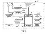
- FIG. 1is a simplified block diagrammatic view of an ACC system in accordance with one embodiment of the present invention.
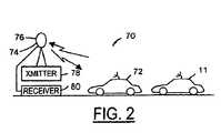
- FIG. 2is a block diagrammatic view of one embodiment of a vehicle network established by the present system.
- FIG. 3is a block diagrammatic view of a vehicle pre-crash sensing system including an ACC system according to one embodiment of the present invention.
- FIG. 4is a perspective view of an automotive vehicle instrument panel display for use with the present invention.
- FIG. 5is a flow chart of the operation of an ACC system according to one embodiment of the present invention.
- While the present inventionis described with respect to an apparatus and method for adaptively adjusting the speed of an automotive vehicle using a control system
- the following apparatus and methodis capable of being adapted for various purposes and is not limited to the following applications: cruise control systems, forward collision warning systems, collision avoidance systems, vehicle systems, or other systems that may require adaptive speed control.
- FIG. 1a block diagrammatic view of a control system 15 located in an automotive vehicle 11 according to an embodiment of the present invention is shown.
- the system 10includes a vehicle controller 12 that is preferably microprocessor-based. Controller 12 is illustrated having a memory 14 therein for storing information related to vehicle position, object detection, and vehicle data. However, memory 14 may also be a separate component. The controller 12 receives signals from several sensors and systems.
- the controller 12receives a detected object profile from a detection system 42 .
- the detection system 42 of the present inventionis preferably radar-based the detection system 42 may be laser based, infrared based, x-ray based, or based off other detection methods known in the art.
- the object profileconsists of an object location relative to the vehicle 11 and a road the vehicle 11 is being operated on.
- the object profilealso consists of distance between the object and the vehicle 11 and the speed of the object relative to the speed of the vehicle 11 .
- the controlleris coupled to a receiver 22 coupled to a receiving antenna 24 and may also be coupled to a transmitter 26 coupled to a transmitting antenna 28 to establish a vehicle-to-vehicle network as described in more detail below with respect to FIG. 3 .
- the controller 12is also coupled to a sensor block 20 that represents various vehicle sensors.
- the controller 12measures the yaw rate of the vehicle 11 using a yaw rate sensor, which represents the level of curvature of a road that the vehicle 11 is being operated on.
- a curved roadmay be an entrance ramp, an exit ramp, or other curved road.
- the controller 12also determines the velocity of the vehicle 11 using a speed signal provided by speed sensor 56 .
- speed sensor 56is illustrated as a single sensor, various numbers of sensors may be employed.
- a suitable speed sensoremploys four sensors, each located at a respective wheel. The speed of the vehicle may be obtained therefrom in a known way similar to that of an anti-lock braking system.
- the controller 12receives a navigation signal from a navigation system 18 .
- the navigation signalmay include vehicle position and location as determined by a Global Positioning System.
- the navigation signalmay also include but is not limited to: vehicle position, speed category, future vehicle path, landmark location, road curvature, overhead object location, bridge location, construction zone, number of lanes, road type, road inclination, road conditions or other data that may effect whether to adjust the speed of the vehicle.
- the controller 12in response to the object profile, the yaw rate, the speed of the vehicle 11 , and the navigation signal determines an operating mode of the system 10 .
- Some of the operating modesare as follows: follow mode, cruise mode, auto resume mode, or inhibit resume mode.
- follow modeis when the system 10 is continuously adjusting the speed of the vehicle 11 to remain a headway or predetermined distance from a target vehicle in the future path of the vehicle 11 .
- cruise modethe system 10 is continuously adjusting the speed of the vehicle 11 to remain at a set speed.
- auto resume modethe system 10 is slowly accelerating the vehicle 11 to a set speed.
- inhibit resume modethe system 10 is not accelerating the vehicle 11 .
- the system 10After determining the system operating mode, the system 10 using the vehicle accelerator 66 or brakes 48 adjusts the speed of the vehicle 11 accordingly.
- the system 10may use the vehicle accelerator 66 or may use a mechanical or electrical throttle control device in adjusting the speed of the vehicle 11 .
- the controller 12may use a warning system 30 to alert the operator of impeding objects in response to the object profile, the yaw rate, the speed at the vehicle, the navigation signal, and the operating mode.
- vehicle 11may be part of a network 70 in conjunction with a second vehicle or various numbers of vehicles represented by reference numeral 72 .
- Vehicle 72preferably is configured in a similar manner to that of vehicle 11 shown in FIG. 1 .
- Vehicle 72may communicate directly with vehicle 11 through transmitter 26 ′ and receiver 22 ′ to form a wireless local area network.
- the network 70may also include a repeater 74 through which vehicle 11 and vehicle 72 may communicate.
- Repeater 74has an antenna 76 coupled to a transmitter 78 and a receiver 80 .
- Various informationcan be communicated through network 70 .
- vehicle data, position data, and sensor datamay all be transmitted to other vehicles throughout network 70 .
- vehicle 11is referred to as the reference vehicle and vehicle 72 is referred to as the target vehicle.
- FIG. 3there is shown one example of a vehicle pre-crash sensing system which includes the ACC system 10 of the present invention as described with reference to FIGS. 1 and 2 .
- the example of FIG. 3provides specific details regarding a preferred vehicle pre-crash sensing system which includes a vehicle-to-vehicle shared data network.
- the present ACC systemis not limited to use in such a vehicle pre-crash sensing system. Rather, the present ACC system may be implemented in any vehicle which includes share vehicle braking data across a wireless network.
- the example of FIG. 3is one such system. To the extent like components have been described with reference to FIG. 1 , reference is made thereto. To the extent further details are beneficial, they will be described herein with respect to FIG. 3 .
- Controller 12is preferably a microprocessor-based controller that is coupled to a memory 14 .
- Controller 12has a CPU 13 that is programmed to perform various tasks.
- Memory 14is illustrated as a separate component from that of controller 12 . However, those skilled in the art will recognize that memory may be incorporated into controller 12 .
- Memory 14may comprise various types of memory including read only memory, random access memory, electrically erasable programmable read only memory, and keep alive memory. Memory 14 is used to store various thresholds and parameters including vehicle data 16 as illustrated.
- Controller 12is coupled to a global positioning system 18 that receives position data triangulated from satellites as is known to those skilled in the art.
- Controller 12is coupled to a sensor data block 20 that represents various sensors located throughout the vehicle. The various sensors will be further described below.
- Controller 12may also be coupled to a receiver 22 coupled to a receiving antenna 24 and a transmitter 26 coupled to a transmitting antenna 28 .
- Controller 12is also coupled to a display 30 that may include various types of displays including a vehicle network display, a warning display 34 , and a counter-measure display 36 .
- display 30may be a single display with different display features or may be individual displays and may include audible warnings as well.
- Controller 12has various functional blocks illustrated within CPU 13 . Although these functional blocks may be represented in software, they may also be carried out in hardware. As will be further described below, controller 12 has a proximity detector 42 that is used to determine the proximity of the various vehicles around automotive vehicle 11 . The proximity detector generates an object detection signal which is used, as described below, to control the headway distance of the ACC. A vehicle trajectory block 44 is used to determine the trajectory of the vehicle and surrounding vehicles. Based upon the vehicle trajectory block 44 , a threat assessment is made in functional block 46 . Of course, threat assessment 46 takes into consideration various vehicle data 16 and sensor data from sensor block 20 . Threat assessment 46 may be made based upon the braking capability of the present vehicle and surrounding vehicles in block 48 and also road conditions of the present vehicle and surrounding vehicles in block 50 . As will be further described below, the road conditions of block 50 may be used to determine the braking capability in block 48 .
- Vehicle datarepresents data that does not change rapidly during operation and thus can be fixed into memory. Various information may change only infrequently and thus may also be fixed into memory 14 .
- Vehicle dataincludes but is not limited to the vehicle type, which may be determined from the vehicle identification number, the weight of the vehicle and various types of tire information.
- Tire informationmay include the tire and type of tread. Such data may be loaded initially during vehicle build and may then manually be updated by a service technician should information such as the tire information change.
- Global positioning system (GPS) 18generates a position signal for the vehicle 11 .
- Global positioning system 18updates its position at a predetermined interval. Typical interval update periods may, for example, be one second. Although this interval may seem long, the vehicle position may be determined based upon the last up update from the GPS and velocity and acceleration information measured within the vehicle.
- Sensor data 20may be coupled to various sensors used in various systems within vehicle 11 .
- Sensor data 20may include a speed sensor 56 that determines the speed of the vehicle.
- Speed sensormay for example be a speed sensor used in an anti-lock brake system. Such sensors are typically comprised of a toothed wheel from which the speed of each wheel can be determined. The speed of each wheel is then averaged to determine the vehicle speed. Of course, those skilled in the art will recognize that the vehicle acceleration can be determined directly from the change in speed of the vehicle.
- a road surface detector 58may also be used as part of sensor data 20 .
- Road surface detector 58may be a millimeter radar that is used to measure the road condition. Road surface detector 58 may also be a detector that uses information from an anti-lock brake system or control system.
- road conditionssuch as black ice, snow, slippery or wet surfaces may be determined.
- slippagecan be determined and therefore the road conditions may be inferred therefrom.
- Such informationmay be displayed to the driver of the vehicle.
- the surface conditionsmay also be transmitted to other vehicles.
- Vehicle data 16has a block 52 coupled thereto representing the information stored therein.
- vehicle datainclude the type, weight, tire information, tire size and tread. Of course, other information may be stored therein.
- Sensor data 20may also include a tire temperature sensor 62 and a tire pressure sensor 64 .
- the road condition and the braking capability of the vehiclemay be determined therefrom.
- Other system sensors 66may generate sensor data 20 including steering wheel angle sensor, lateral acceleration sensor, yaw sensor, longitudinal acceleration sensor, gyroscopic sensors and other types of sensors.
- Other system sensors 66may additionally include an operator attention system which provides a modifying value to the braking capability system 48 if the driver of the reference vehicle is distracted. Thus, the attention of the driver can be factored into the braking capability value.
- the operator attention systemcan indicate that the driver is potentially distracted and, thus, less likely to react to a vehicle braking situation. In such cases, the vehicle headway distance can be increased with respect to the target vehicle.
- Distraction indicatorscan include operation of the audio controls, wireless phone operation, manipulation of any of the vehicle comfort features (seat or mirror adjustments in progress) or other, similar indicators of potential operator distraction. In a similar manner, any distractions on the part of the target vehicle operator can be accounted for in the target vehicle braking capability value.
- Similar vehicle data 16 and sensor data 20is received from detected vehicles within the vehicle network by way of the receiver 22 .
- the vehicle type, weight, tire information, tire size, tire pressure, tire temperature, road conditions, vehicle speed, and braking capability of the vehicle being followed by the reference vehicleis received.
- a braking capability value for the target vehiclecan be determined by the controller 13 .
- the target vehiclecan transmit only a braking capability value to the reference vehicle 11 .
- This valuerepresents a scaling factor by which the ACC system of the vehicle 11 adjusts its reference headway distance value to account for the braking capability of the target vehicle. Headway distance modification is described in more detail below with reference to FIG. 5 .
- an instrument panel 82having a first display 84 and a second display 86 .
- Either displays 84 , 86may be used generate various information related to the pre-crash sensing system and ACC system. For example, when the braking capability of either the reference vehicle 11 or target vehicle 72 is less than optimum due to road conditions or otherwise, the displays 84 , 86 may indicate a warning or notice.
- the vehicle network display 32may include a map 88 , a reference vehicle indicator, and a target vehicle indicator.
- First vehicle indicatorcorresponds to the vehicle in which the pre-crash sensing system is while target vehicle indicator corresponds to an approaching vehicle.
- Vehicle network display 32may be displayed when a vehicle is near but beyond a certain distance or threat level.
- Warning display 34in addition to the display information shown in vehicle network display in FIG. 3 , can include a warning indicator and a distance indicator.
- the distance indicatorprovides the vehicle operator with an indication of the distance from a target vehicle.
- the warning display 34may be indicated when the vehicle is within a predetermined distance or threat level more urgent than that of vehicle network display 32 .
- a counter-measure display 36can indicate to the vehicle operator that a counter-measure is being activated because the threat level is high or the distance from the target vehicle is within a predetermined distance less than the distances needed for activation of the other displays.
- step 100the various sensors for the system are read.
- step 102various vehicle data is read.
- decision block 104it is determined whether the ACC system is activated. If the ACC system is active, in step 106 , the information from a detected, second vehicle is obtained.
- the second vehicleis the target vehicle, ahead of the reference vehicle, which is followed at a headway distance according to known ACC operating principles.
- the second vehicle information receivedis the braking capability of the second vehicle as described above. It may also be various information such as the speed, heading, vehicle type, position, tire data, and road conditions from the other vehicle or vehicles in the network.
- the proximity of the first vehicle and second vehicleis determined.
- the proximityis merely a distance calculation.
- the first vehicle trajectory relative to the second vehicleis determined.
- the first vehicle trajectoryuses the information such as the positions and various sensors to predict a path for the first vehicle and the second vehicle.
- the vehicle headway distanceis modified as a function of the braking capabilities of the first vehicle and/or second vehicle. Headway distance may also be modified based upon conditions of the vehicle trajectory and vehicle type as well as based upon tire information which may provide indication as to the braking capability of the first vehicle and/or the second vehicle. Thus, the headway distance may be adjusted accordingly. Also, the road surface condition may also be factored into the headway adjustment. On clear, dry roads the headway distance may be shorter as compared with when the vehicle is operating under the same conditions with wet or snowy roads.
- headway distancemay be adjusted accordingly.
- the braking capability of the reference vehiclemay also be used in the headway distance modification.
- the displaysmay also be updated in step 114 based upon the braking capabilities of the target vehicle and/or the reference vehicle.
- the braking capabilitiesmay be determined from various tire type, size, tread, tire pressure, tire temperature, outside temperature as well as the road condition, vehicle speed and vehicle weight.
- the braking capabilitycan also include a driver attention factor as described above. For example, the reference headway distance may be increased if either or both the reference and target vehicle operators are determined to be distracted from giving their full attention to driving.
- the reference vehicle ACC systemUnder normal operating conditions, when the reference vehicle ACC system is active, the system maintains a reference headway distance with a target vehicle. This is typically on the order of a one second separation.
- the relative and absolute speeds of the respective vehicles as well as the trajectories of both vehicles as determined by vehicle sensor data and shared vehicle data,is used to maintain the reference vehicle at the set speed while maintaining the reference headway distance.
- the reference headway distanceis then modified, in accordance with the present invention, as follows. If the braking capability of the reference vehicle is less than optimum, the reference headway distance is increased. Any number of factors, some of which are mentioned above as sensor data points, can compromise braking capability including, but not limited to: slippery road conditions, low tire pressure, excessive tire temperature, worn brakes, increased vehicle speed, or increased vehicle loading (weight). These factors or data points can be summed and/or weighted to determine a braking capability value (BC R ) for the reference vehicle. In a similar manner, either the sensor data from the target vehicle or, preferably, a braking capability value (BC T ) for the target vehicle is also received by the reference vehicle.
- BC Rbraking capability value
- the reference headway distancecan be increased or safely decreased.
- the systemtakes into account the relative instantaneous potential stopping distances of the target vehicle and reference vehicle and adjusts the headway distance value such that a safe distance is maintained between the vehicles at all times during normal ACC operation.
- the more compromised the braking capability of the reference vehicle, or the more distracted the reference vehicle operatorthe greater the headway distance.
- the more compromised the target vehicle braking capability vis-à-vis the reference vehiclethe shorter the headway distance.
- a distracted target vehicle operatormay also result in an increased headway distance with respect to a reference headway distance as a distracted driver may be more likely to react strongly or more unpredictably to a situation.
- various informationmay be known to drivers of other nearby vehicles.
- the presence of black ice and other slippery conditions not readily apparentmay be transmitted to other vehicles for avoidance thereof.
Landscapes
- Engineering & Computer Science (AREA)
- Transportation (AREA)
- Mechanical Engineering (AREA)
- Chemical & Material Sciences (AREA)
- Combustion & Propulsion (AREA)
- Automation & Control Theory (AREA)
- Physics & Mathematics (AREA)
- General Physics & Mathematics (AREA)
- Traffic Control Systems (AREA)
- Control Of Driving Devices And Active Controlling Of Vehicle (AREA)
- Regulating Braking Force (AREA)
Abstract
Description
Claims (20)
Priority Applications (1)
| Application Number | Priority Date | Filing Date | Title |
|---|---|---|---|
| US10/065,440US6882923B2 (en) | 2002-10-17 | 2002-10-17 | Adaptive cruise control system using shared vehicle network data |
Applications Claiming Priority (1)
| Application Number | Priority Date | Filing Date | Title |
|---|---|---|---|
| US10/065,440US6882923B2 (en) | 2002-10-17 | 2002-10-17 | Adaptive cruise control system using shared vehicle network data |
Publications (2)
| Publication Number | Publication Date |
|---|---|
| US20040078133A1 US20040078133A1 (en) | 2004-04-22 |
| US6882923B2true US6882923B2 (en) | 2005-04-19 |
Family
ID=32092187
Family Applications (1)
| Application Number | Title | Priority Date | Filing Date |
|---|---|---|---|
| US10/065,440Expired - LifetimeUS6882923B2 (en) | 2002-10-17 | 2002-10-17 | Adaptive cruise control system using shared vehicle network data |
Country Status (1)
| Country | Link |
|---|---|
| US (1) | US6882923B2 (en) |
Cited By (20)
| Publication number | Priority date | Publication date | Assignee | Title |
|---|---|---|---|---|
| US20040138814A1 (en)* | 2003-01-13 | 2004-07-15 | Konkan Railway Corporation Ltd. | Anti-collision device |
| US20060015241A1 (en)* | 2004-07-16 | 2006-01-19 | Nissan Motor Co., Ltd. | Preceding vehicle following cruise control system |
| US20070164896A1 (en)* | 2005-11-10 | 2007-07-19 | Hitachi, Ltd. | In-vehicle radar device and communication device |
| US20080243334A1 (en)* | 2007-03-29 | 2008-10-02 | Bujak Christopher R | Vehicle Control System With Advanced Tire Monitoring |
| US20090237293A1 (en)* | 2008-03-21 | 2009-09-24 | Denso Corporation | Recognition system for vehicle |
| US20090237291A1 (en)* | 2008-03-21 | 2009-09-24 | Denso Corporation | Recognition system for vehicle |
| US20110071746A1 (en)* | 2009-09-21 | 2011-03-24 | Ford Global Technologies, Llc | Assisted direct start engine control for enhanced launch performance |
| US20110106364A1 (en)* | 2003-04-30 | 2011-05-05 | Goetz Braeuchle | Device for speed control and distance control in motor vehicles |
| US20110153178A1 (en)* | 2009-12-23 | 2011-06-23 | Honda Motor Co., Ltd. | Vehicle driver coaching system and method |
| US8014928B2 (en) | 2008-06-17 | 2011-09-06 | Ford Global Technologies, Llc | Automotive slipstreaming support system |
| US20120283928A1 (en)* | 2009-11-30 | 2012-11-08 | Volvo Lastvagnar Ab | Method and system for controlling a vehicle cruise control |
| US20130090802A1 (en)* | 2011-10-07 | 2013-04-11 | Southwest Research Institute | Waypoint splining for autonomous vehicle following |
| US20130173114A1 (en)* | 2011-12-30 | 2013-07-04 | Unnikrishna Sreedharan Pillai | Method and apparatus for automobile accident reduction using localized dynamic swarming |
| US8725342B2 (en)* | 2012-04-27 | 2014-05-13 | Google Inc. | Safely navigating on roads through maintaining safe distance from other vehicles |
| US20150178998A1 (en)* | 2013-12-20 | 2015-06-25 | Ford Global Technologies, Llc | Fault handling in an autonomous vehicle |
| US20180148050A1 (en)* | 2015-06-12 | 2018-05-31 | Hitachi Construction Machinery Co., Ltd. | On-board terminal device and vehicle collision prevention method |
| US10520321B1 (en)* | 2015-12-10 | 2019-12-31 | Lytx, Inc. | Route safety score |
| US11285810B2 (en) | 2005-11-17 | 2022-03-29 | Invently Automotive Inc. | Vehicle power management system |
| US11370302B2 (en) | 2005-11-17 | 2022-06-28 | Invently Automotive Inc. | Electric vehicle power management system |
| WO2023168216A1 (en)* | 2022-03-01 | 2023-09-07 | Continental Autonomous Mobility US, LLC | Dynamically adjusting adaptive cruise control |
Families Citing this family (62)
| Publication number | Priority date | Publication date | Assignee | Title |
|---|---|---|---|---|
| US7689230B2 (en)* | 2004-04-01 | 2010-03-30 | Bosch Rexroth Corporation | Intelligent transportation system |
| US20090118908A1 (en)* | 2004-06-21 | 2009-05-07 | Fuller Bros., Inc. | Vehicle Safety Zone System |
| DE502005010775D1 (en)* | 2004-10-29 | 2011-02-10 | Continental Teves Ag & Co Ohg | PROCESS FOR INCREASING THE SAFETY AND / OR COMFORT OF A MOTOR VEHICLE |
| JP4127403B2 (en)* | 2005-02-28 | 2008-07-30 | 独立行政法人 宇宙航空研究開発機構 | Method and apparatus for stabilizing control of vehicle traffic |
| DE102005026065A1 (en)* | 2005-06-07 | 2006-12-21 | Robert Bosch Gmbh | Adaptive speed controller with situation-dependent dynamic adaptation |
| JP2009511321A (en)* | 2005-10-07 | 2009-03-19 | イートン コーポレーション | Adaptive cruise control for heavy duty vehicles |
| US20070083318A1 (en)* | 2005-10-07 | 2007-04-12 | Parikh Jayendra S | Adaptive cruise control using vehicle-to-vehicle wireless communication |
| WO2008043842A2 (en)* | 2006-10-13 | 2008-04-17 | Continental Teves Ag & Co. Ohg | Vehicle and method for identifying vehicles located in the surroundings of the vehicle |
| US8355852B2 (en)* | 2007-05-04 | 2013-01-15 | GM Global Technology Operations LLC | Slow or stopped vehicle ahead advisor with digital map integration |
| DE102008036131B4 (en) | 2007-08-29 | 2023-08-24 | Continental Autonomous Mobility Germany GmbH | Method and device for detecting the traffic situation in a vehicle environment |
| DE102008014771A1 (en)* | 2008-03-18 | 2009-09-24 | Wabco Gmbh | Adaptive cruise control |
| WO2011013202A1 (en) | 2009-07-28 | 2011-02-03 | トヨタ自動車株式会社 | Vehicle control device, vehicle control method, and vehicle control system |
| EP2461304A4 (en) | 2009-07-28 | 2013-02-27 | DEVICE, METHOD AND CONTROL SYSTEM FOR VEHICLE | |
| JP5435034B2 (en)* | 2009-07-29 | 2014-03-05 | トヨタ自動車株式会社 | Vehicle control apparatus, vehicle control method, and vehicle control system |
| JP5453048B2 (en)* | 2009-10-22 | 2014-03-26 | 富士重工業株式会社 | Vehicle driving support control device |
| FR2970210B1 (en)* | 2011-01-10 | 2013-08-02 | Peugeot Citroen Automobiles Sa | SYSTEM FOR CONTROLLING THE SPEED OF A VEHICLE BASED ON THE CONDITION OF TIRES |
| US10520952B1 (en) | 2011-07-06 | 2019-12-31 | Peloton Technology, Inc. | Devices, systems, and methods for transmitting vehicle data |
| US10520581B2 (en) | 2011-07-06 | 2019-12-31 | Peloton Technology, Inc. | Sensor fusion for autonomous or partially autonomous vehicle control |
| US20170242443A1 (en) | 2015-11-02 | 2017-08-24 | Peloton Technology, Inc. | Gap measurement for vehicle convoying |
| US9582006B2 (en) | 2011-07-06 | 2017-02-28 | Peloton Technology, Inc. | Systems and methods for semi-autonomous convoying of vehicles |
| WO2018039114A1 (en) | 2016-08-22 | 2018-03-01 | Peloton Technology, Inc. | Systems for vehicular platooning and methods therefor |
| US11334092B2 (en) | 2011-07-06 | 2022-05-17 | Peloton Technology, Inc. | Devices, systems, and methods for transmitting vehicle data |
| DE102011118252A1 (en)* | 2011-11-11 | 2013-05-16 | Audi Ag | Method for operating a start-stop system of a motor vehicle and motor vehicle |
| DE102012002695B4 (en)* | 2012-02-14 | 2024-08-01 | Zf Cv Systems Hannover Gmbh | Procedure for determining an emergency braking situation of a vehicle |
| US9620014B2 (en)* | 2012-11-29 | 2017-04-11 | Nissan North America, Inc. | Vehicle intersection monitoring system and method |
| US11294396B2 (en) | 2013-03-15 | 2022-04-05 | Peloton Technology, Inc. | System and method for implementing pre-cognition braking and/or avoiding or mitigation risks among platooning vehicles |
| US20180210463A1 (en) | 2013-03-15 | 2018-07-26 | Peloton Technology, Inc. | System and method for implementing pre-cognition braking and/or avoiding or mitigation risks among platooning vehicles |
| KR20150056000A (en)* | 2013-11-14 | 2015-05-22 | 주식회사 만도 | Adaptive cruise control apparatus of vehicle with sensing distance regulation function and method for thereof |
| US10583700B2 (en)* | 2014-12-26 | 2020-03-10 | The Yokohama Rubber Co., Ltd. | Tire state monitoring system |
| CN107406077B (en)* | 2015-02-26 | 2021-06-01 | 沃尔沃卡车集团 | Method of controlling the gap between vehicles in a fleet |
| US9869560B2 (en) | 2015-07-31 | 2018-01-16 | International Business Machines Corporation | Self-driving vehicle's response to a proximate emergency vehicle |
| US9785145B2 (en) | 2015-08-07 | 2017-10-10 | International Business Machines Corporation | Controlling driving modes of self-driving vehicles |
| US9721397B2 (en) | 2015-08-11 | 2017-08-01 | International Business Machines Corporation | Automatic toll booth interaction with self-driving vehicles |
| US9718471B2 (en)* | 2015-08-18 | 2017-08-01 | International Business Machines Corporation | Automated spatial separation of self-driving vehicles from manually operated vehicles |
| US9896100B2 (en) | 2015-08-24 | 2018-02-20 | International Business Machines Corporation | Automated spatial separation of self-driving vehicles from other vehicles based on occupant preferences |
| US9731726B2 (en) | 2015-09-02 | 2017-08-15 | International Business Machines Corporation | Redirecting self-driving vehicles to a product provider based on physiological states of occupants of the self-driving vehicles |
| US9566986B1 (en) | 2015-09-25 | 2017-02-14 | International Business Machines Corporation | Controlling driving modes of self-driving vehicles |
| US9834224B2 (en) | 2015-10-15 | 2017-12-05 | International Business Machines Corporation | Controlling driving modes of self-driving vehicles |
| US9944291B2 (en) | 2015-10-27 | 2018-04-17 | International Business Machines Corporation | Controlling driving modes of self-driving vehicles |
| US9751532B2 (en) | 2015-10-27 | 2017-09-05 | International Business Machines Corporation | Controlling spacing of self-driving vehicles based on social network relationships |
| US10607293B2 (en) | 2015-10-30 | 2020-03-31 | International Business Machines Corporation | Automated insurance toggling for self-driving vehicles |
| CN105172791A (en)* | 2015-10-30 | 2015-12-23 | 东风汽车公司 | Smart self-adaptive cruise control method |
| US10176525B2 (en) | 2015-11-09 | 2019-01-08 | International Business Machines Corporation | Dynamically adjusting insurance policy parameters for a self-driving vehicle |
| US9791861B2 (en) | 2015-11-12 | 2017-10-17 | International Business Machines Corporation | Autonomously servicing self-driving vehicles |
| US10061326B2 (en) | 2015-12-09 | 2018-08-28 | International Business Machines Corporation | Mishap amelioration based on second-order sensing by a self-driving vehicle |
| US9836973B2 (en) | 2016-01-27 | 2017-12-05 | International Business Machines Corporation | Selectively controlling a self-driving vehicle's access to a roadway |
| US10685391B2 (en) | 2016-05-24 | 2020-06-16 | International Business Machines Corporation | Directing movement of a self-driving vehicle based on sales activity |
| JP7005526B2 (en) | 2016-05-31 | 2022-01-21 | ぺロトン テクノロジー インコーポレイテッド | State machine of platooning controller |
| JP6778872B2 (en)* | 2016-06-28 | 2020-11-04 | パナソニックIpマネジメント株式会社 | Driving support device and driving support method |
| US10369998B2 (en) | 2016-08-22 | 2019-08-06 | Peloton Technology, Inc. | Dynamic gap control for automated driving |
| US10093322B2 (en) | 2016-09-15 | 2018-10-09 | International Business Machines Corporation | Automatically providing explanations for actions taken by a self-driving vehicle |
| US10643256B2 (en) | 2016-09-16 | 2020-05-05 | International Business Machines Corporation | Configuring a self-driving vehicle for charitable donations pickup and delivery |
| US10259452B2 (en) | 2017-01-04 | 2019-04-16 | International Business Machines Corporation | Self-driving vehicle collision management system |
| US10529147B2 (en) | 2017-01-05 | 2020-01-07 | International Business Machines Corporation | Self-driving vehicle road safety flare deploying system |
| US10363893B2 (en) | 2017-01-05 | 2019-07-30 | International Business Machines Corporation | Self-driving vehicle contextual lock control system |
| US10152060B2 (en) | 2017-03-08 | 2018-12-11 | International Business Machines Corporation | Protecting contents of a smart vault being transported by a self-driving vehicle |
| JP6996155B2 (en)* | 2017-08-10 | 2022-01-17 | いすゞ自動車株式会社 | Operation information management device, operation information management method, and operation information management system |
| US10899323B2 (en) | 2018-07-08 | 2021-01-26 | Peloton Technology, Inc. | Devices, systems, and methods for vehicle braking |
| US10762791B2 (en) | 2018-10-29 | 2020-09-01 | Peloton Technology, Inc. | Systems and methods for managing communications between vehicles |
| US11167759B2 (en)* | 2019-04-10 | 2021-11-09 | GM Global Technology Operations LLC | Method and apparatus for controlling a vehicle including an adaptive cruise control system |
| US11427196B2 (en) | 2019-04-15 | 2022-08-30 | Peloton Technology, Inc. | Systems and methods for managing tractor-trailers |
| KR20220056305A (en)* | 2020-10-27 | 2022-05-06 | 현대자동차주식회사 | Platooning controlling apparatus based on driver condition, system having the same and method thereof |
Citations (12)
| Publication number | Priority date | Publication date | Assignee | Title |
|---|---|---|---|---|
| US5572449A (en) | 1994-05-19 | 1996-11-05 | Vi&T Group, Inc. | Automatic vehicle following system |
| US5594645A (en)* | 1993-05-19 | 1997-01-14 | Mazda Motor Corporation | Cruise controller for vehicles |
| US5749426A (en) | 1994-12-13 | 1998-05-12 | Lucas Industries Public Limited Company | Apparatus and method for cruise control |
| US6178372B1 (en)* | 1996-06-07 | 2001-01-23 | Toyota Jidosha Kabushiki Kaisha | Motor vehicle drive system controller and automatic drive controller |
| US6233515B1 (en) | 1998-12-07 | 2001-05-15 | Jaguar Car, Limited | Adaptive vehicle cruise control system and methodology |
| US6256574B1 (en) | 1998-02-06 | 2001-07-03 | Bayerische Motoren Werke Aktiengesellschaft | Distance-related cruise control system |
| US6285153B1 (en) | 1999-12-22 | 2001-09-04 | Visteon Global Technologies, Inc. | Method and system for adjusting headway in an adaptive speed control system based on road surface coefficient of friction |
| US6311121B1 (en) | 1998-01-19 | 2001-10-30 | Hitachi, Ltd. | Vehicle running control apparatus, vehicle running control method, and computer program product having the method stored therein |
| US6324465B1 (en)* | 1999-03-26 | 2001-11-27 | Denso Corporation | Automatic cruising control apparatus |
| US20020039472A1 (en)* | 2000-07-31 | 2002-04-04 | Hirokazu Takeuti | Preliminary member of optical device component with optical fiber |
| US6516262B2 (en)* | 2000-02-23 | 2003-02-04 | Hitachi, Ltd. | Running control device for a vehicle |
| US6546327B2 (en)* | 2000-08-29 | 2003-04-08 | Toyota Jidosha Kabushiki Kaisha | Running control apparatus and method |
- 2002
- 2002-10-17USUS10/065,440patent/US6882923B2/ennot_activeExpired - Lifetime
Patent Citations (12)
| Publication number | Priority date | Publication date | Assignee | Title |
|---|---|---|---|---|
| US5594645A (en)* | 1993-05-19 | 1997-01-14 | Mazda Motor Corporation | Cruise controller for vehicles |
| US5572449A (en) | 1994-05-19 | 1996-11-05 | Vi&T Group, Inc. | Automatic vehicle following system |
| US5749426A (en) | 1994-12-13 | 1998-05-12 | Lucas Industries Public Limited Company | Apparatus and method for cruise control |
| US6178372B1 (en)* | 1996-06-07 | 2001-01-23 | Toyota Jidosha Kabushiki Kaisha | Motor vehicle drive system controller and automatic drive controller |
| US6311121B1 (en) | 1998-01-19 | 2001-10-30 | Hitachi, Ltd. | Vehicle running control apparatus, vehicle running control method, and computer program product having the method stored therein |
| US6256574B1 (en) | 1998-02-06 | 2001-07-03 | Bayerische Motoren Werke Aktiengesellschaft | Distance-related cruise control system |
| US6233515B1 (en) | 1998-12-07 | 2001-05-15 | Jaguar Car, Limited | Adaptive vehicle cruise control system and methodology |
| US6324465B1 (en)* | 1999-03-26 | 2001-11-27 | Denso Corporation | Automatic cruising control apparatus |
| US6285153B1 (en) | 1999-12-22 | 2001-09-04 | Visteon Global Technologies, Inc. | Method and system for adjusting headway in an adaptive speed control system based on road surface coefficient of friction |
| US6516262B2 (en)* | 2000-02-23 | 2003-02-04 | Hitachi, Ltd. | Running control device for a vehicle |
| US20020039472A1 (en)* | 2000-07-31 | 2002-04-04 | Hirokazu Takeuti | Preliminary member of optical device component with optical fiber |
| US6546327B2 (en)* | 2000-08-29 | 2003-04-08 | Toyota Jidosha Kabushiki Kaisha | Running control apparatus and method |
Cited By (33)
| Publication number | Priority date | Publication date | Assignee | Title |
|---|---|---|---|---|
| US20040138814A1 (en)* | 2003-01-13 | 2004-07-15 | Konkan Railway Corporation Ltd. | Anti-collision device |
| US20110106364A1 (en)* | 2003-04-30 | 2011-05-05 | Goetz Braeuchle | Device for speed control and distance control in motor vehicles |
| US20060015241A1 (en)* | 2004-07-16 | 2006-01-19 | Nissan Motor Co., Ltd. | Preceding vehicle following cruise control system |
| US7460946B2 (en)* | 2004-07-16 | 2008-12-02 | Nissan Motor Co., Ltd. | Preceding vehicle following cruise control system |
| US20070164896A1 (en)* | 2005-11-10 | 2007-07-19 | Hitachi, Ltd. | In-vehicle radar device and communication device |
| US11370302B2 (en) | 2005-11-17 | 2022-06-28 | Invently Automotive Inc. | Electric vehicle power management system |
| US11285810B2 (en) | 2005-11-17 | 2022-03-29 | Invently Automotive Inc. | Vehicle power management system |
| US20080243334A1 (en)* | 2007-03-29 | 2008-10-02 | Bujak Christopher R | Vehicle Control System With Advanced Tire Monitoring |
| US8032281B2 (en)* | 2007-03-29 | 2011-10-04 | Ford Global Technologies | Vehicle control system with advanced tire monitoring |
| US8255118B2 (en) | 2007-03-29 | 2012-08-28 | Ford Global Technologies | Vehicle control system with advanced tire monitoring |
| US8255117B2 (en) | 2007-03-29 | 2012-08-28 | Ford Global Technologies | Vehicle control system with advanced tire monitoring |
| US20090237291A1 (en)* | 2008-03-21 | 2009-09-24 | Denso Corporation | Recognition system for vehicle |
| US20090237293A1 (en)* | 2008-03-21 | 2009-09-24 | Denso Corporation | Recognition system for vehicle |
| US8077077B2 (en)* | 2008-03-21 | 2011-12-13 | Denso Corporation | Recognition system for vehicle |
| US8014928B2 (en) | 2008-06-17 | 2011-09-06 | Ford Global Technologies, Llc | Automotive slipstreaming support system |
| US9677530B2 (en) | 2009-09-21 | 2017-06-13 | Ford Global Technologies, Llc | Assisted direct start engine control for enhanced launch performance |
| US20110071746A1 (en)* | 2009-09-21 | 2011-03-24 | Ford Global Technologies, Llc | Assisted direct start engine control for enhanced launch performance |
| US20120283928A1 (en)* | 2009-11-30 | 2012-11-08 | Volvo Lastvagnar Ab | Method and system for controlling a vehicle cruise control |
| US20110153178A1 (en)* | 2009-12-23 | 2011-06-23 | Honda Motor Co., Ltd. | Vehicle driver coaching system and method |
| US8463521B2 (en)* | 2009-12-23 | 2013-06-11 | Honda Motor Co., Ltd. | Vehicle driver coaching system and method |
| US8510029B2 (en)* | 2011-10-07 | 2013-08-13 | Southwest Research Institute | Waypoint splining for autonomous vehicle following |
| US20130090802A1 (en)* | 2011-10-07 | 2013-04-11 | Southwest Research Institute | Waypoint splining for autonomous vehicle following |
| US9187118B2 (en)* | 2011-12-30 | 2015-11-17 | C & P Technologies, Inc. | Method and apparatus for automobile accident reduction using localized dynamic swarming |
| US20130173114A1 (en)* | 2011-12-30 | 2013-07-04 | Unnikrishna Sreedharan Pillai | Method and apparatus for automobile accident reduction using localized dynamic swarming |
| US8725342B2 (en)* | 2012-04-27 | 2014-05-13 | Google Inc. | Safely navigating on roads through maintaining safe distance from other vehicles |
| US9406177B2 (en)* | 2013-12-20 | 2016-08-02 | Ford Global Technologies, Llc | Fault handling in an autonomous vehicle |
| US20150178998A1 (en)* | 2013-12-20 | 2015-06-25 | Ford Global Technologies, Llc | Fault handling in an autonomous vehicle |
| US20180148050A1 (en)* | 2015-06-12 | 2018-05-31 | Hitachi Construction Machinery Co., Ltd. | On-board terminal device and vehicle collision prevention method |
| US10640108B2 (en)* | 2015-06-12 | 2020-05-05 | Hitachi Construction Machinery Co., Ltd. | On-board terminal device and vehicle collision prevention method |
| US10520321B1 (en)* | 2015-12-10 | 2019-12-31 | Lytx, Inc. | Route safety score |
| WO2023168216A1 (en)* | 2022-03-01 | 2023-09-07 | Continental Autonomous Mobility US, LLC | Dynamically adjusting adaptive cruise control |
| US20230278558A1 (en)* | 2022-03-01 | 2023-09-07 | Continental Autonomous Mobility US, LLC | Dynamically adjusting adaptive cruise control |
| US12194996B2 (en)* | 2022-03-01 | 2025-01-14 | Continental Autonomous Mobility US, LLC | Dynamically adjusting adaptive cruise control |
Also Published As
| Publication number | Publication date |
|---|---|
| US20040078133A1 (en) | 2004-04-22 |
Similar Documents
| Publication | Publication Date | Title |
|---|---|---|
| US6882923B2 (en) | Adaptive cruise control system using shared vehicle network data | |
| US6442484B1 (en) | Method and apparatus for pre-crash threat assessment using spheroidal partitioning | |
| US6662108B2 (en) | Method and apparatus for improving a vehicle safety system using a transponder and GPS | |
| US11173898B2 (en) | Driver assistance system for a motor vehicle | |
| US20030139881A1 (en) | Method and apparatus for activating a crash countermeasure | |
| US6480102B1 (en) | Method and apparatus for activating a crash countermeasure in response to the road condition | |
| US6813562B2 (en) | Threat assessment algorithm for forward collision warning | |
| EP3707045B1 (en) | Warning and adjusting the longitudinal speed of a motor vehicle based on the recognized road traffic lights | |
| US9937860B1 (en) | Method for detecting forward collision | |
| WO2019242768A1 (en) | Tailgating alert system in vehicles | |
| US9020728B2 (en) | Vehicle turn monitoring system and method | |
| CN105564441B (en) | Alarm device, warning system, alarming method and portable terminal | |
| EP3707046B1 (en) | Adjusting the longitudinal motion control of a host motor vehicle based on the estimation of the travel trajectory of a leading motor vehicle | |
| EP2022694A1 (en) | System and method for controlling running of a vehicle | |
| US8463521B2 (en) | Vehicle driver coaching system and method | |
| US20070150196A1 (en) | Method for detecting or predicting vehicle cut-ins | |
| US7653472B2 (en) | Devices, systems and methods for prohibition of acceleration for cooperative speed control system | |
| EP2405416B1 (en) | Adaptive cruise control method and system for controlling speed of vehicle | |
| US20080088479A1 (en) | Traffic light warning method and system | |
| US6502034B1 (en) | Method and apparatus for activating a crash countermeasure using a transponder and adaptive cruise control | |
| US20220194411A1 (en) | Vehicle collision avoidance system and method | |
| US6609057B2 (en) | Method and apparatus for activating a crash countermeasure using a transponder having various modes of operation | |
| US6609066B2 (en) | Method and apparatus for activating a crash countermeasure in response to the braking capability of a vehicle | |
| US6658355B2 (en) | Method and apparatus for activating a crash countermeasure | |
| WO2015121260A1 (en) | Apparatus and method for use in a vehicle |
Legal Events
| Date | Code | Title | Description |
|---|---|---|---|
| AS | Assignment | Owner name:FORD MOTOR COMPANY, MICHIGAN Free format text:ASSIGNMENT OF ASSIGNORS INTEREST;ASSIGNORS:MILLER, RONALD HUGH;THROOP, MEDVILLE JAY;BASCH, RENA HECHT;REEL/FRAME:013185/0357;SIGNING DATES FROM 20020911 TO 20021006 Owner name:FORD GLOBAL TECHNOLOGIES, INC., MICHIGAN Free format text:ASSIGNMENT OF ASSIGNORS INTEREST;ASSIGNOR:FORD MOTOR COMPANY;REEL/FRAME:013185/0396 Effective date:20021008 | |
| AS | Assignment | Owner name:FORD GLOBAL TECHNOLOGIES, LLC, MICHIGAN Free format text:MERGER;ASSIGNOR:FORD GLOBAL TECHNOLOGIES, INC.;REEL/FRAME:013987/0838 Effective date:20030301 Owner name:FORD GLOBAL TECHNOLOGIES, LLC,MICHIGAN Free format text:MERGER;ASSIGNOR:FORD GLOBAL TECHNOLOGIES, INC.;REEL/FRAME:013987/0838 Effective date:20030301 | |
| STCF | Information on status: patent grant | Free format text:PATENTED CASE | |
| FPAY | Fee payment | Year of fee payment:4 | |
| FPAY | Fee payment | Year of fee payment:8 | |
| FPAY | Fee payment | Year of fee payment:12 |