US6882833B2 - Transferring data in a wireless communication system - Google Patents
Transferring data in a wireless communication systemDownload PDFInfo
- Publication number
- US6882833B2 US6882833B2US10/079,751US7975102AUS6882833B2US 6882833 B2US6882833 B2US 6882833B2US 7975102 AUS7975102 AUS 7975102AUS 6882833 B2US6882833 B2US 6882833B2
- Authority
- US
- United States
- Prior art keywords
- frequency
- data stream
- component
- unit
- data
- Prior art date
- Legal status (The legal status is an assumption and is not a legal conclusion. Google has not performed a legal analysis and makes no representation as to the accuracy of the status listed.)
- Expired - Lifetime, expires
Links
- 238000004891communicationMethods0.000titleclaimsabstractdescription26
- 102000002067Protein SubunitsHuman genes0.000claimsabstractdescription8
- 108010001267Protein SubunitsProteins0.000claimsabstractdescription8
- 238000000034methodMethods0.000claimsdescription36
- 238000005516engineering processMethods0.000claimsdescription5
- 238000010295mobile communicationMethods0.000claimsdescription3
- 230000007246mechanismEffects0.000abstractdescription8
- 239000000872bufferSubstances0.000description14
- 238000012545processingMethods0.000description6
- 230000003044adaptive effectEffects0.000description5
- 230000005540biological transmissionEffects0.000description3
- 238000004806packaging method and processMethods0.000description2
- 238000013459approachMethods0.000description1
- 230000001413cellular effectEffects0.000description1
- 230000008878couplingEffects0.000description1
- 238000010168coupling processMethods0.000description1
- 238000005859coupling reactionMethods0.000description1
- 238000013461designMethods0.000description1
- 239000000463materialSubstances0.000description1
- 238000012986modificationMethods0.000description1
- 230000004048modificationEffects0.000description1
- 238000001228spectrumMethods0.000description1
Images


Classifications
- H—ELECTRICITY
- H04—ELECTRIC COMMUNICATION TECHNIQUE
- H04B—TRANSMISSION
- H04B7/00—Radio transmission systems, i.e. using radiation field
- H04B7/02—Diversity systems; Multi-antenna system, i.e. transmission or reception using multiple antennas
- H04B7/12—Frequency diversity
Definitions
- the present inventionrelates generally to wireless communication systems, and more specifically to transferring data in such systems.
- Antennasare commonly used in wireless communication systems in which the antennas radiate power for signals to be received and transmitted through the antennas to appropriate signal transmitters and receivers.
- Adaptive antennarefers to an array of antennas capable of dynamically changing its antenna pattern to adjust to noise, interference, and different paths of users using the antenna, etc.
- Adaptive antennasform beams for transmission and enhance signals because they can adjust their patterns to track mobile users.
- Switched beam technologiesuse a number of beams at an antenna site for the receiver to select the beam that provides the best signals.
- Smart-antenna systemsusually include both adaptive antennas and switched beam technologies.
- the number of antennas in an array for use in adaptive antennas and/or smart antennasvaries depending on the applications using the antennas, the distance between the wireless transmitters and receivers, whether the system processing the wireless signals are powerful or not, etc.
- the more antennas are used in a systemthe better it is for the system's reception and transmission performance.
- transferring the data through the antennasbecomes more difficult and expensive because adding antennas to a system results in additional components and costs to the system. For example, in various cases, additional radio-frequency (RF) data paths must be added, and, as the number of these paths increases, the interface between the paths and the baseband chip becomes more complicated.
- RFradio-frequency
- the present inventionprovides mechanisms for transferring data in wireless communications systems.
- the datais transferred in an access point (AP) used in a wireless local area network (WLAN), which comprises a wireless communication system connected to a local area network (LAN).
- the access pointincludes a baseband chip capable of adapting various radio frequency (RF) units.
- RFradio frequency
- Each RF unitin turns includes a plurality of RF sub units connected as a daisy chain.
- Each RF sub unitis also connected to at least one antenna.
- the access pointthus includes a number of antennas that, together with the RF units and the baseband chip, form a smart antenna.
- the data received from the smart antennatravels through the RF sub units in each RF unit, and the data from the RF units travels to the baseband chip.
- the data transmitted from the baseband chiptravels to the RF units, and in each RF unit the data travels through the sub units to the smart antenna.
- each RF sub unitis removably connected to another RF sub unit, and each RF unit is removably connected to the baseband chip, which allows flexibility in selecting a system configuration with an appropriate number of antennas for the smart antenna.
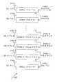
- FIG. 1shows a wireless communication system upon which embodiments of the invention may be implemented
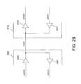
- FIG. 2Ashows an access point in accordance with one embodiment
- FIG. 2Billustrates a mechanism in which one connecting point between an RF unit and the baseband unit may be used for both a receiving mode and a transmitting mode
- FIG. 3shows a RF unit in accordance with one embodiment
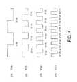
- FIG. 4shows the data traveling through four exemplary RF sub units, in accordance with one embodiment
- FIG. 5shows a RF sub unit in accordance with one embodiment
- FIG. 6shows a receiving unit in accordance with one embodiment
- FIG. 7Ashows a first type of an interleaver in accordance with one embodiment
- FIG. 7Bshows a second type of an interleaver in accordance with one embodiment
- FIG. 8shows a transmitting unit in accordance with one embodiment
- FIG. 9Ashows a first type of a de-interleaver in accordance with one embodiment
- FIG. 9Bshows a second type of a de-interleave in accordance with one embodiment.
- FIG. 10shows a baseband unit in accordance with one embodiment.
- FIG. 1shows a wireless communication system 100 upon which embodiments of the invention may be implemented.
- Exemplary technologies used in system 100include the code-division multiple access (CDMA), the time-division multiple access (TDMA), the global system for mobile communications (GSM), etc.
- System 100includes an access point 125 and a plurality of stations 130 - 1 , 130 - 2 , . . . , 130 -N.
- Access point 125includes an access station 110 connected to a smart antenna 120 .
- access point 125is connected to an electronic network (not shown), which transmits information through access station 110 , smart antenna 120 , and wirelessly to stations 130 .
- the networkwirelessly receives information from stations 130 through smart antenna 120 and access station 110 , etc.
- access station 110processes signals received or sent through antenna 120 .
- access point 125allows signal beams radiating through antenna 120 to be focused to that station 130 .
- a local area networkis used as the network in the above discussion.
- the inventionis not limited to LANs, other networks are within the scope of the invention, including, for example, the digital subscriber line (DSL), the Ethernet, the cable modem, etc.
- LANis a computer network that spans a relatively small area. Most LANs are confined to a single building or group of buildings
- a station 130is a mobile device wirelessly communicating with the network through access point 125 .
- Examples of a station 130include a laptop or a desktop computer, a personal digital assistance (PDA), a cellular phone, etc.
- PDApersonal digital assistance
- Each station 130includes at least one antenna and a processing unit processing signals to communicate wirelessly with access point 125 .
- the processing unitmay be different from access station 110 , but, in general, perform the same function as access station 110 . Even though stations 130 are moveable from one position to another position, to communicate effectively with access point 125 , a station 130 must be within the coverage range of access point 125 .
- This coverage rangevaries depending on various factors including the transmitting frequency, the number of antennas in smart antenna 120 or in stations 130 , the power of each antenna, the processing power of access station 110 and of the processing unit in stations 130 , etc.
- a lower-frequency systemhas a wider range of coverage than a higher-frequency system.
- a system with the IEEE 802.11b or 802.11g protocolhas a coverage area four times greater than that of the 802.11a protocol because the 802.11b and 802.11g protocol operates at a 2.4 Ghz frequency, which is much slower than the 5.0 Ghz frequency of the 802.11a protocol.
- IEEEstands for the “Institute of Electrical and Electronics Engineers.”
- FIG. 2Ashows access point 125 having a plurality of RF units 220 ( 1 ) to 220 (M) connected to a baseband unit or baseband chip 210 at lines 2300 ( 1 ) to 2300 (M), respectively, in accordance with one embodiment.
- a RF unit 220includes a plurality of RF sub units 2200 (not shown), each of which carries at least one antenna. The antennas of all RF sub units 2200 , together with RF sub units 2200 and baseband chip 210 , function as smart antenna 120 .
- RF units 220process the analog radio frequency signals received from smart antenna 120 , down-convert the radio frequency to the intermediate frequency, combine and digitize the signals, etc.
- baseband chip 210demodulates the digitized signals received from RF units 220 , converts them to the digital domain of zeros and ones, and sends them to the LAN, etc.
- baseband chip 210receives the digital data from the LAN, modulates the data, and sends it to RF units 220 .
- RF units 220upon receiving the digital data, convert it to analog, up-convert the data's intermediate frequency to the radio frequency, and send the data to smart antenna 120 , which transmits the data over the air.
- each RF unit 220is removably connected to baseband chip 210 . That is, each unit 220 is easily removed from or attached to baseband chip 210 , which can be done by any convenient mechanism. In embodiments where printed-circuit boards (PCBs) are used to implement units 220 and baseband chip 210 , any mechanism for connecting PCBs is effective.
- PCBsprinted-circuit boards
- each RF unit 220uses only one connecting point at line 2300 for both receiving and transmitting. In embodiments that allow both receiving and transmitting at the same time, each RF unit 220 uses one connecting point for receiving and one connecting point for transmitting. Reducing connecting points between a RF unit 220 and baseband chip 210 simplifies the design of baseband chip 210 and reduces its packaging costs.
- FIG. 2Bshows one embodiment in which one connecting point at a line 2300 is used for both receiving and transmitting.
- a RF unit 220is connected at line 2300 with baseband chip 210 .
- RF unit 220includes a tristate buffer 240 R and a tristate buffer 240 T
- baseband chip 210includes a tristate buffer 250 R and a tristate buffer 250 T.
- buffers 240 R and 250 Rare enabled while buffers 240 T and 250 T are disabled so that the data on line 2400 R travels through buffer 240 R, line 2300 , and buffer 250 R, to line 2500 R.
- buffers 240 R and 250 Rare disabled while buffers 240 T and 250 T are enabled so that the data on line 2500 T travels through buffer 250 T, line 2300 , and buffer 240 T, to line 2500 T.
- FIG. 3shows a unit 220 including L number of sub units 2200 , e.g., sub unit 2200 ( 1 ) to sub unit 2200 (L), in accordance with one embodiment.
- each sub unit 2200is connected to at least one antenna, and the number of antennas per sub unit 2200 can be conveniently selected.
- the distance between two antennasequals to 1 ⁇ 4 of the wavelength of the carrier or wallet frequency of the antenna.
- a wavelength of a signalis one over the frequency of that signal.
- FIG. 3shows that each RF sub unit 2200 ( 1 ) to 2200 (L) is connected to an antenna 310 ( 1 ) to 310 (L), respectively.
- Each antenna 310is associated with a carrier RF frequency F( 1 ) to F(L).
- Each sub unit 2200down-converts each RF frequency F( 1 ) to F(L) into each intermediate frequency (IF), which, through a serializing process, is transformed into each frequency F′′( 1 ) to F′′(L), respectively.
- IFintermediate frequency
- the data received from each antenna 310is referred to as data D( 1 ) to data D(L), respectively.
- Each sub unit 2200also transforms data D( 1 ) to data D(L) into data D′′( 1 ) to data D′′(L), respectively, each of which corresponds to each frequency F′′.
- RF sub units 2200are connected serially or as a daisy chain. That is, a first sub unit is connected to a second sub unit, the second sub unit is connected to a third sub unit, etc., and the last sub unit is connected to baseband chip 210 .
- FIG. 3shows that sub unit 2200 (L) is connected to sub unit 2200 (L ⁇ 1) at line 3100 (L); sub unit 2200 (L ⁇ 1) is connected to sub unit 2200 (L ⁇ 2) at line 3100 (L ⁇ 1); sub unit 2200 (L ⁇ 2) is connected to sub unit 2200 (L ⁇ 3) at line 3100 (L ⁇ 2), etc., until sub unit 2200 ( 2 ) is connected to sub unit 2200 ( 1 ) at line 3100 ( 2 ).
- sub unit 2200 ( 1 )(or RF unit 220 as a whole) is connected to baseband chip 210 at line 3100 ( 1 ), which is a line 2300 in FIG. 2 A.
- line 3100 ( 1 )is a line 2300 in FIG. 2 A.
- data D′( 1 ) to D′(L)are referred to as data D′( 1 ) to D′(L).
- frequency transmitted at line 3100 ( 1 ) to line 3100 (L)is referred to as frequency F′( 1 ) to frequency F′(L), respectively.
- data D′(L) on line 3100 (L)corresponds to data D′′(L).
- Data D′(L)is sent through sub unit 2200 (L ⁇ 1), which combines data D′′(L ⁇ 1) and data D′(L) to form data D′(L ⁇ 1) on line 3100 (L ⁇ 1).
- Data D′(L ⁇ 1)is sent through sub unit 2200 (L ⁇ 2), which combines data D′′(L ⁇ 2) and data D′(L ⁇ 1) to form data D′(L ⁇ 2), etc.
- data D′( 2 )is sent through sub unit 2200 ( 1 ), which combines data D′′( 1 ) and data D′( 2 ) to form data D′( 1 ) online 3100 ( 1 ).
- data D′( 1 )is the combined data of data D′′( 1 ) to data D′′(L).
- data D′(I)is the combined data of data D′′(I) and data D′′(I+1).
- data D′( 2 )is the combined data of data D′′( 2 ) and data D′( 3 ), wherein data D′( 3 ) is the combined data of data D′′( 3 ) and data D′′( 4 ).
- data D′( 1 ) on line 3100 ( 1 )corresponds to the combined data D′′( 1 ) to D′′(L).
- Data D′( 1 )is sent to sub unit 2200 ( 1 ), which keeps the data D′′( 1 ) for itself and sends the rest of the data to sub unit 2200 ( 2 ) on line 3100 ( 2 ).
- Sub unit 2200 ( 2 )keeps the data D′′( 2 ) for itself and sends the rest of the data to sub unit 2200 ( 3 ) on line 3100 ( 3 ), etc.
- data D′(L)which corresponds to data D′′(L) is sent through line 3100 (L) to sub unit 2200 (L).
- Each RF frequency Fcan be any frequency within the electromagnetic spectrum associated with radio wave propagation, and can be different for one antenna 310 to another antenna 310 .
- all frequencies Fare substantially the same, and are compatible with the IEEE 802.11 standard, which runs at 2.4 GZ to 5.0 GHZ.
- frequency F′( 1 ) to F′(L)corresponds to the frequency of data D′( 1 ) to data D′(L), respectively.
- frequency F′(L)corresponds to frequency F′′(L); frequency F′(L ⁇ 1) is the sum of frequency F′′(L ⁇ 1) and frequency F′(L); frequency F′(L ⁇ 2) is the sum of frequency F′′(L ⁇ 2) and frequency F′(L ⁇ 1); and frequency F′( 1 ) is the sum of frequency F′′( 1 ) and frequency F′( 2 ) or the sum of all frequency F′′( 1 ) to frequency F′′(L). If I is an integer, then frequency F′(I) is the sum of frequency F′′(I) and frequency F′(I+1). For illustrated purposes, let L equals to 4 and each frequency F′′( 1 ) to F′′( 4 ) equals to 10 MHZ, then frequency F′( 1 ) equals to 40 MHZ (10 MHZ*4).
- the maximum frequency allowable for frequency F′( 1 ), or the maximum frequency allowable at line 3100 ( 1 ),determines the maximum number of RF sub units 2200 allowable in a daisy chain in a unit 220 .
- This maximum frequency allowable for frequency F′( 1 )varies depending on various factors, including, for example, the material forming the printed-circuit board (PCB) implementing RF units 220 and baseband chip 210 , the noise tolerance of the PCB, the distance between RF units 220 and baseband chip 210 , etc. In general, the longer the distance, the lower the frequency is allowable because of the noise coupling and signal distortion, etc.
- each frequency F′′ of each RF sub unit 2200equals to each other, then the maximum number of sub units 2200 allowable in a daisy chain in a unit 220 is obtained by dividing the maximum frequency allowable for frequency F′( 1 ) by the frequency F′′. Consequently, if each frequency F′′ equals to 10 MHZ, and the maximum frequency allowable for frequency F′( 1 ) is 100 MHZ, then the maximum number of sub units 2200 allowable in the daisy chain is 10 (100 MHZ/10 MHZ). Similarly, if the maximum frequency allowable for F′( 1 ) is 150 MHZ, then the maximum number of sub units 2200 allowable in the daisy chain is 15 (150 MHZ/10 MHZ), etc.
- each sub unit 2200is removably connected to another sub unit in unit 220 . Consequently, depending on the number of antennas desired for a particular application, a combination of a number of antennas per sub unit 2200 , a number of sub units 2200 per unit 220 , and a number of units 220 per baseband chip 210 may be selected. For example, if six antennas are desired, then two antennas per each sub units 2200 , and three sub units 2200 per each unit 220 may be selected. Alternatively, one antenna per each sub unit 2200 , three sub units 2200 per unit 220 , and two units 220 may be selected, etc.
- the inventionis not limited to a number of antennas per sub unit 2200 , a number of sub units 2200 per unit 220 , or a number of units 220 connected to baseband chip 210 .
- additional antennasare added to a sub unit 2200 , additional sub units 2200 are added to units 220 , and/or additional units 220 are added to baseband chip 210 , additional antennas are added to baseband chip 210 .
- additional antennasare added to smart antenna 120 and access point 125 .
- Each RF sub unit 2200may be removably connected to each other by any convenient mechanism. In embodiments where printed circuit boards (PCBs) are used to implement sub units 2200 , any mechanism for connecting PCBs is effective.
- PCBsprinted circuit boards
- FIG. 4for an illustration of how data D′′( 1 ) to D′′(L) is combined into data D′( 1 ) on line 3100 ( 1 ), in accordance with one embodiment.
- there are four sub units 2200 in a unit 220i.e., L equals to 4.
- each stream of data D′′( 1 ) to data D′′( 4 )runs at a 10 MHZ frequency.
- sub unit 2200 ( 4 )transmits data D′′( 4 ) to line 3100 ( 4 ) as data D′( 4 ) running at 10 MHZ frequency.
- sub unit 2200 ( 3 )combines data D′′( 3 ) and data D′( 4 ) to form data D′( 3 ) running at 20 MHZ.
- Data D′( 3 )includes data D′′( 3 ) and D′′( 4 ).
- sub unit 2200 ( 2 )combines data D′′( 2 ) and data D′( 3 ) to form data D′( 2 ) running at 30 MHZ.
- Data D′( 2 )includes data D′′( 2 ), D′′( 3 ), and D′′( 4 ).
- sub unit 2200 ( 1 )combines data D′′( 1 ) and data D′( 2 ) to form data D′( 1 ) running at 40 MHZ.
- Data D′( 1 )includes data D′′( 1 ), D′′( 2 ), D′′( 3 ), and D′′( 4 ).
- FIG. 4shows data D′( 3 ), D′( 2 ), and D′( 1 ) having data D′′ in the order of D′′( 4 ) and D′′( 3 ); D′′( 4 ), D′′( 3 ), and D′′( 2 ); and D′′( 4 ), D′′( 3 ), D′′( 2 ), and D′′( 1 ), respectively.
- the inventionis not limited to a particular order of data D′′ in each data D′. Any order of data D′′ in each data D′ is within the scope of the invention.
- data D′( 3 ), D′( 2 ), and D′( 1 )may include data D′′ in the reverse order shown in FIG. 4 . That is, data D′( 3 ), D′( 2 ), and D′( 1 ) may include data D′′ in the order of D′′( 3 ) and D′′( 4 ); D′′( 2 ), D′′( 3 ), and D′′( 4 ), and D′′( 1 ), D′′( 2 ), D′′( 3 ), and D′′( 4 ), respectively, etc.
- each data D′′is earmarked so that baseband chip 210 can identify data D′′ in data D′( 1 ).
- baseband chip 210sends data D′′( 4 ), D′′( 3 ), D′′( 2 ), and D′′( 1 ) as data D′( 1 ) on line 3100 ( 1 ) to sub unit 2200 ( 1 ).
- Data D′( 1 )runs at a 40 MHZ frequency.
- Sub unit 2200 ( 1 )keeps data D′′( 1 ) for itself, and, as shown on line 3 , sends data D′′( 4 ), D′′( 3 ), and D′′( 2 ) as data D′( 2 ) to sub unit 2200 ( 2 ).
- Data D′( 2 )runs at 30 MHZ.
- Sub unit 2200 ( 2 )keeps data D′′( 2 ) for itself, and, on line 2 , sends data D′′( 4 ) and D′′( 3 ) as data D′( 3 ) to sub unit 2200 ( 3 ).
- Data D′( 3 )runs at 20 MHZ.
- Sub unit 2200 ( 3 )keeps data D′′( 3 ) for itself, and, on line 1 , sends data D′′( 4 ) as data D′( 4 ) to sub unit 2200 ( 4 ).
- Data D′( 4 )runs at 10 MHZ.
- FIG. 5shows a RF sub unit 2200 having a receiving unit 504 and a transmitting unit 508 , in accordance with one embodiment.
- Receiving unit 504receives data from antenna 310 through line 5100 , processed the data, and sends the processed data through line 5300 and line 3100 to baseband chip 210 .
- Baseband chip 210sends the data through line 3100 and line 5400 to transmitting unit 508 , which processes the data, and sends the processed data through line 5200 to antenna 310 .
- lines 5300 and 5400may be implemented as lines 2400 R and 2500 T in FIG. 2B , respectively.
- FIG. 6shows a receiving unit 504 in accordance with one embodiment.
- Receiving unit 504includes a down-converter 605 , an analog-to-digital converter (ADC) 610 , a serializer 620 , and an interleaver 630 .
- Down-converter 605converts the radio frequency of the signals on line 6050 to the intermediate frequency on line 6100 .
- the signal on line 6050is the data received from antenna 310 and corresponds to data D running at a frequency F in FIG. 3 .
- Line 6050also corresponds to line 5100 in FIG. 5 .
- ADC 610converts the data in analog form on line 6100 to digital form on line 6150 .
- Serializer 620converts the data on line 6150 to the data on line 6250 , which, in one embodiment, corresponds to data D′′ in FIG. 3 .
- Interleaver 630combines data D′′ on line 6250 and the data on line 6270 to form the data on line 6300 , which corresponds to line 5300 in FIG. 5 . If I is an integer, and if receiving unit 604 is in a sub unit 2200 (I) in FIG. 3 , then line 6300 corresponds to line 3100 (I) while line 6270 corresponds to line 3100 (I+1). For example, if I equals to 1 then line 6300 corresponds to line 3100 ( 1 ) while line 6270 corresponds to line 3100 ( 2 ).
- line 6300corresponds to line 3100 ( 3 ) while line 6270 corresponds to line 3100 ( 4 ), etc. If I equals to L, then line 6300 corresponds to line 3100 (L), and there is no line 6270 .
- FIGS. 7A and 7Bshow two different types of interleaver 630 , in accordance with one embodiment.
- interleaver 630 (L)corresponds to a RF sub unit 2200 (L), which is the last sub unit in a daisy chain.
- Interleaver 630 (L)includes a buffer 710 A that passes data D′′(L) on line 6250 as data D′(L) on line 3100 (L). If L equals to 4, then data D′′( 4 ) equals to D′( 4 ) shown on line 1 in FIG. 4 .
- FIG. 7Bshows an interleaver 530 (I) corresponding to a RF sub unit 2200 (I).
- Interleaver 530 (I)includes a multiplexer (mux) 710 B having lines 6250 (I) and 3100 (I+1) as inputs and line 3100 (I) as output.
- the data on line 6250 (I) and on line 3100 (I+1)corresponds to data D′′(I) running at a 10 MHZ frequency and D′(I+1) running at a frequency of 10 MHZ*(L ⁇ I).
- mux 710 Bselects the data on line 6250 (I) in the first 100 NS/(L ⁇ I+1), and selects the data on line 3100 (I+1) in the next (L ⁇ I) times, each for a period of 100 NS/(L ⁇ I+1), resulting in data D′(I) on line 3100 (I) running at 100 NS/(L ⁇ I+1) periods or a (L ⁇ I+1)*10 MHZ frequency.
- line 6250 (I)corresponds to line 6250 ( 3 ) and line 3100 (I+1) equals to line 3100 ( 4 ).
- the data on line 6250 ( 3 ) and on line 3100 ( 4 )correspond to data D′′( 3 ) and D′( 4 ), which corresponds to data D′′( 4 ), respectively, each of which runs at a 10 MHZ frequency or a plurality of 100 NS periods.
- mux 710 BFor each 100 NS period of the output, mux 710 B selects data D′′( 3 ) on line 6250 ( 3 ) for the first 50 NS, and selects data D′( 4 ) on line 3100 ( 4 ) for the second 50 NS, resulting in data D′( 3 ) on line 3100 ( 3 ) running at 50 NS periods or a 20 MHZ frequency. Data D′( 3 ) is shown on line 2 in FIG. 4 .
- line 6250 (I)corresponds to line 6250 ( 2 ) and line 3100 (I+1) corresponds to line 3100 ( 3 ).
- the data on line 6250 ( 2 ) and on line 3100 ( 3 )correspond to data D′′( 2 ) running at a 10 MHZ frequency and data D′( 3 ) running at a 20 MHZ frequency.
- mux 710 BFor each 100 NS period of the output, mux 710 B selects data D′′( 2 ) on line 6250 ( 2 ) in the first 33.33 NS, and selects the data on line 3100 ( 3 ) in the next two 33.33 NS, resulting in data D′( 2 ) on line 3100 ( 2 ) running at 33.33 NS periods or a 30 MHZ frequency. Data D′( 2 ) is shown on line 3 in FIG. 4 .
- line 6250 (I)corresponds to line 6250 ( 1 )
- line 3100 (I+1)corresponds to line 3100 ( 2 ).
- the data on line 6250 ( 1 ) and on line 3100 ( 2 )correspond to data D′′( 1 ) running at a 10 MHZ frequency and data D′( 2 ) running at a 30 MHZ frequency.
- Data D′( 2 )is the combination of data D′′( 4 ) and data D′′( 3 ).
- mux 710 BFor each 100 NS period of the output, mux 710 B selects data D′′( 1 ) on line 6250 ( 1 ) in the first 25 NS, and selects data D′( 2 ) on line 3100 ( 2 ) in the next three 25 NS, resulting in data D′( 1 ) on line 3100 ( 1 ) running at 25 NS periods or a 40 MHZ frequency. Data D′( 1 ) is shown on line 4 in FIG. 4 .
- the Transimitting UnitThe Transimitting Unit
- FIG. 8shows a transmitting unit 508 of FIG. 5 , in accordance with one embodiment.
- Transmitting unit 508includes a de-interleaver 810 , a de-serializer 820 , a digital to analog (DAC) 830 , and an up-converter 840 .
- DACdigital to analog
- De-interleaver 810separates the data on line 8050 into the data on line 8100 and the data on line 8150 .
- Line 8050corresponds to line 5400 in FIG. 5 . If I is an integer, and if receiving unit 508 is in a sub unit 2200 (I) in FIG. 3 , then line 8050 corresponds to line 3100 (I) while line 8150 corresponds to line 3100 (I+1). For example, if I equals to 1 then line 8050 corresponds to line 3100 ( 1 ) while line 8150 corresponds to line 3100 ( 2 ). If I equals to 3 then line 8050 corresponds to line 3100 ( 3 ) while line 8150 corresponds to line 3100 ( 4 ), etc. If I equals to L, then line 8050 corresponds to line 3100 (L), and there is no line 8150 .
- De-serializer 820converts the data on line 8100 to the data on line 8200 .
- the data on line 8100in one embodiment, corresponds to data D′′ in FIG. 3 .
- DAC 830converts the data in digital form on line 8200 to analog form on line 8300 .
- Up-converter 840converts the intermediate frequency of the data on line 8300 to the radio frequency on line 8400 .
- the data on line 8400corresponds to data D running at a frequency F in FIG. 3 and is transmitted to antenna 310 .
- Line 8400also corresponds to line 5200 in FIG. 5
- the De-interleaverThe De-interleaver
- FIGS. 9A and 9Bshow two different types of de-interleavers 810 , in accordance with one embodiment.
- FIG. 9Ashows a de-interleaver 810 ( 1 ) corresponding to a RF sub unit 2200 (I).
- De-interleaver 810 (I)includes a de-mux 910 A having line 3100 (I) as input and lines 8100 (I) and 3100 (I+1) as outputs.
- the data on line 3100 (I)runs at a (L ⁇ I+1)* 10 MHZ frequency and includes the data D′′(I) to data D′′(L).
- de-mux 910 AFor each 100 NS of data D′(I), de-mux 910 A assigns the first 100 NS/(L ⁇ I+1) to line 8100 ( 1 ) running at 10 MHZ and the next (L ⁇ I) times of 100 NS/(L ⁇ I+1) to line 3100 (I+1) running at (L ⁇ I)*10 MHZ.
- the data on line 8100 (I)corresponds to data D′′(I) while the data on line 3100 (I+1) corresponds to data D′(I+1).
- line 3100 (I)corresponds to line 3100 ( 1 )
- line 8100 (I)corresponds to line 8100 ( 1 )
- line 3100 (I+1)corresponds to line 3100 ( 2 ).
- the data on line 3100 ( 1 )corresponds to data D′( 1 ) and runs at a 40 MHZ frequency or 25 NS periods.
- Data D′( 1 )includes the data D′′( 1 ), data D′′( 2 ), data D′′( 3 ), and data D′′( 4 ).
- de-mux 910 Aassigns the first 25 NS to line 8100 ( 1 ) running at 10 MHZ and the next three 25 NS to line 3100 ( 2 ) running at 30 MHZ.
- the data on line 8100 ( 1 )corresponds to data D′′( 1 ) while the data on line 3100 ( 2 ) corresponds to data D′( 2 ).
- Data D′( 1 )is shown on line 4 and data D′( 2 ) is shown on line 3 in FIG. 4 .
- line 3100 (I)corresponds to line 3100 ( 2 )
- line 8100 (I)corresponds to line 8100 ( 2 )
- line 3100 (I+1)corresponds to line 3100 ( 3 ).
- the data on line 3100 ( 2 )corresponds to data D′( 2 ) and runs at a 30 MHZ frequency or 33.33 NS periods.
- Data D′( 2 )includes data D′′( 2 ), data D′′( 3 ), and data D′′( 4 ).
- de-mux 910 Aassigns the first 33.33 NS to line 8100 ( 2 ) running at 10 MHZ and the next two 33.33 NS to line 3100 ( 3 ) running at 20 MHZ.
- the data on line 8100 ( 2 )corresponds to data D′′( 2 ) while the data on line 3100 ( 3 ) corresponds to data D′( 3 ).
- Data D′( 2 )is shown on line 3 and data D′( 3 ) is shown on line 2 in FIG. 4 .
- line 3100 (I)corresponds to line 3100 ( 3 )
- line 8100 (I)corresponds to line 8100 ( 3 )
- line 3100 (I+1)corresponds to line 3100 ( 4 ).
- the data on line 3100 ( 3 )corresponds to data D′( 3 ) and runs at a 20 MHZ frequency or 50 NS periods.
- Data D′( 3 )includes data D′′( 3 ) and data D′′( 4 ).
- de-mux 910 Aassigns the first 50 NS to line 8100 ( 3 ) running at 10 MHZ and the next 50 NS to line 3100 ( 4 ) running at 10 MHZ.
- the data on line 8100 ( 3 )corresponds to data D′′( 3 ) while the data on line 3100 ( 4 ) corresponds to data D′( 4 ), which corresponds to data D′′( 4 ).
- Data D′( 3 )is shown on line 2 and data D′( 4 ) is shown on line 1 in FIG. 4 .
- de-interleaver 810 (L)corresponds to a RF sub unit 2200 (L), which is the last sub unit in a daisy chain.
- De-interleaver 810 (L)includes a buffer 910 B that passes data D′(L) on line 3100 (L) as data D′′(L) on line 8100 (L). If L equals to 4, then data D′′( 4 ) equals to data D′( 4 ) shown on line 1 in FIG. 4 .
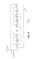
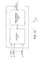
- FIG. 10shows a baseband chip 210 in accordance with one embodiment.
- Chip 210includes an interface 1010 and a smart-antenna DSP engine 1020 .
- Interface 1010receives data D′′( 1 ) to data D′′(L) in the combined form for each line 2300 ( 1 ) to 2300 (M) in FIG. 2 A.
- the data on line 2300 for each RF unit 220corresponds to data D′( 1 ) on line 3100 ( 1 ) in FIG. 3 .
- interface 1010separates the combined data D′( 1 ) to each data D′′ corresponding to each RF sub unit 2200 and its associated antenna 310 .
- interface 1010recognizes data D′′ of each RF sub unit based on the order the data D′′ is sent to interface 1010 . For example, in the example of FIG.
- interface 1010receives data D′( 1 ) in the order of sub unit 2200 ( 1 ) to sub unit 2200 (L), e.g., in the order of data D′′( 1 ) to data D′′(L). Recognizing the frequency and the order of data D′′ in data D′( 1 ), interface 1010 can identify D′′ for each sub unit 2200 .
- Lequals to 4
- data D′( 1 ) received at interface 1010runs at a 40 MHZ frequency or a plurality of 25 NS periods.
- data D′( 1 )includes the data in the order of data D′′( 1 ), data D′′( 2 ), data D′′( 3 ), and data D′′( 4 ) for the first, the second, the third, and the fourth 25 NS, respectively. Consequently, interface 1010 can accordingly identify each data D′′.
- interface 1010can use a signal earmarked in data D′′ and thus data D′( 1 ) to identify data D′′. Data D′′ is earmarked when it is sent through its corresponding RF sub units 2200 .
- the inventionis not limited to a method for interface 1010 to recognize the data and its associated antenna.
- interface 1010when interface 1010 sends data to a RF unit 220 , interface 1010 combines the data corresponding to each RF sub units 2200 into data D′( 1 ) which runs at a frequency being the sum of the frequency of the data D′′ for each sub unit 2200 .
- Each sub unit 2200via its de-interleaver, keeps the data for itself, and sends the rest of the data to the next sub unit 2200 as explained above.
- Smart antenna DSP engine 1020uses the adaptive array techniques to process the data accordingly. For example, in the receiving mode, engine 1020 processes the data received from each antenna 310 , e.g., data D′′( 1 ) to data D′′(L), then sends the processed data to be further processed by the network layers such as the physical layer (PHY) and the media access control (MAC) layer. The data is eventually sent to the network, which in one embodiment is the LAN. Similarly, in the transmitting mode, engine 1020 receives the data from the LAN via the network layers, processes the data, then sends the data to interface 1010 , etc.
- PHYphysical layer
- MACmedia access control
Landscapes
- Engineering & Computer Science (AREA)
- Computer Networks & Wireless Communication (AREA)
- Signal Processing (AREA)
- Mobile Radio Communication Systems (AREA)
Abstract
Description
Claims (41)
Priority Applications (1)
| Application Number | Priority Date | Filing Date | Title |
|---|---|---|---|
| US10/079,751US6882833B2 (en) | 2002-02-22 | 2002-02-22 | Transferring data in a wireless communication system |
Applications Claiming Priority (1)
| Application Number | Priority Date | Filing Date | Title |
|---|---|---|---|
| US10/079,751US6882833B2 (en) | 2002-02-22 | 2002-02-22 | Transferring data in a wireless communication system |
Publications (2)
| Publication Number | Publication Date |
|---|---|
| US20030181221A1 US20030181221A1 (en) | 2003-09-25 |
| US6882833B2true US6882833B2 (en) | 2005-04-19 |
Family
ID=28038759
Family Applications (1)
| Application Number | Title | Priority Date | Filing Date |
|---|---|---|---|
| US10/079,751Expired - LifetimeUS6882833B2 (en) | 2002-02-22 | 2002-02-22 | Transferring data in a wireless communication system |
Country Status (1)
| Country | Link |
|---|---|
| US (1) | US6882833B2 (en) |
Cited By (13)
| Publication number | Priority date | Publication date | Assignee | Title |
|---|---|---|---|---|
| US20040090947A1 (en)* | 2002-11-07 | 2004-05-13 | Wilborn Thomas B. | Method, apparatus, and system for receiving data on a first frequency band and observing a second frequency band |
| US20060221922A1 (en)* | 2005-03-29 | 2006-10-05 | Hon Hai Precision Industry Co., Ltd. | Communication system with access point |
| US8577301B1 (en)* | 2007-03-21 | 2013-11-05 | Qualcomm Incorporated | Analog baseband interface for communication systems |
| US9037143B2 (en) | 2010-08-16 | 2015-05-19 | Corning Optical Communications LLC | Remote antenna clusters and related systems, components, and methods supporting digital data signal propagation between remote antenna units |
| US9042732B2 (en) | 2010-05-02 | 2015-05-26 | Corning Optical Communications LLC | Providing digital data services in optical fiber-based distributed radio frequency (RF) communication systems, and related components and methods |
| US9325429B2 (en) | 2011-02-21 | 2016-04-26 | Corning Optical Communications LLC | Providing digital data services as electrical signals and radio-frequency (RF) communications over optical fiber in distributed communications systems, and related components and methods |
| US9525488B2 (en) | 2010-05-02 | 2016-12-20 | Corning Optical Communications LLC | Digital data services and/or power distribution in optical fiber-based distributed communications systems providing digital data and radio frequency (RF) communications services, and related components and methods |
| US10096909B2 (en) | 2014-11-03 | 2018-10-09 | Corning Optical Communications Wireless Ltd. | Multi-band monopole planar antennas configured to facilitate improved radio frequency (RF) isolation in multiple-input multiple-output (MIMO) antenna arrangement |
| US10110308B2 (en) | 2014-12-18 | 2018-10-23 | Corning Optical Communications Wireless Ltd | Digital interface modules (DIMs) for flexibly distributing digital and/or analog communications signals in wide-area analog distributed antenna systems (DASs) |
| US10135533B2 (en) | 2014-11-13 | 2018-11-20 | Corning Optical Communications Wireless Ltd | Analog distributed antenna systems (DASS) supporting distribution of digital communications signals interfaced from a digital signal source and analog radio frequency (RF) communications signals |
| US10187151B2 (en) | 2014-12-18 | 2019-01-22 | Corning Optical Communications Wireless Ltd | Digital-analog interface modules (DAIMs) for flexibly distributing digital and/or analog communications signals in wide-area analog distributed antenna systems (DASs) |
| US10659163B2 (en) | 2014-09-25 | 2020-05-19 | Corning Optical Communications LLC | Supporting analog remote antenna units (RAUs) in digital distributed antenna systems (DASs) using analog RAU digital adaptors |
| US11178609B2 (en) | 2010-10-13 | 2021-11-16 | Corning Optical Communications LLC | Power management for remote antenna units in distributed antenna systems |
Families Citing this family (42)
| Publication number | Priority date | Publication date | Assignee | Title |
|---|---|---|---|---|
| US7158501B2 (en)* | 2001-05-29 | 2007-01-02 | Kabushiki Kaisha Toshiba | Wireless communication apparatus |
| US7272358B2 (en)* | 2002-03-07 | 2007-09-18 | Texas Instruments Incorporated | Channelization scheme for wireless local area networks |
| US8380143B2 (en) | 2002-05-01 | 2013-02-19 | Dali Systems Co. Ltd | Power amplifier time-delay invariant predistortion methods and apparatus |
| US8811917B2 (en) | 2002-05-01 | 2014-08-19 | Dali Systems Co. Ltd. | Digital hybrid mode power amplifier system |
| US6907229B2 (en)* | 2002-05-06 | 2005-06-14 | Extricom Ltd. | Enhancing wireless LAN capacity using transmission power control |
| US7177661B2 (en)* | 2002-05-06 | 2007-02-13 | Extricom Ltd. | Communication between wireless access points over LAN cabling |
| US7319688B2 (en)* | 2002-05-06 | 2008-01-15 | Extricom Ltd. | LAN with message interleaving |
| US20030206532A1 (en)* | 2002-05-06 | 2003-11-06 | Extricom Ltd. | Collaboration between wireless lan access points |
| US7697549B2 (en)* | 2002-08-07 | 2010-04-13 | Extricom Ltd. | Wireless LAN control over a wired network |
| US20050195786A1 (en)* | 2002-08-07 | 2005-09-08 | Extricom Ltd. | Spatial reuse of frequency channels in a WLAN |
| US20060209771A1 (en)* | 2005-03-03 | 2006-09-21 | Extricom Ltd. | Wireless LAN with contention avoidance |
| US20040162037A1 (en)* | 2003-02-18 | 2004-08-19 | Eran Shpak | Multi-channel WLAN transceiver with antenna diversity |
| JP2006520137A (en) | 2003-02-18 | 2006-08-31 | エクストリコム リミティド | Multiplexing between access point and hub |
| US20050058111A1 (en)* | 2003-09-15 | 2005-03-17 | Pai-Fu Hung | WLAN device having smart antenna system |
| US20060223453A1 (en)* | 2005-03-21 | 2006-10-05 | Griffin G S | Frequency shifted wireless local area network system |
| US7813738B2 (en)* | 2005-08-11 | 2010-10-12 | Extricom Ltd. | WLAN operating on multiple adjacent bands |
| US20080112373A1 (en)* | 2006-11-14 | 2008-05-15 | Extricom Ltd. | Dynamic BSS allocation |
| WO2008067685A1 (en)* | 2006-12-04 | 2008-06-12 | Zte Corporation | A wireless communication apparatus and the configuration method thereof |
| CN101682558B (en)* | 2006-12-07 | 2013-07-17 | Lg电子株式会社 | Method for transferring data in wireless communication system |
| KR101342365B1 (en)* | 2006-12-07 | 2013-12-16 | 엘지전자 주식회사 | Method of transferring data in wireless communication system |
| US8797879B2 (en)* | 2006-12-07 | 2014-08-05 | Lg Electronics Inc. | Method of transmitting and receiving status report in a mobile communication system |
| CN102017553B (en) | 2006-12-26 | 2014-10-15 | 大力系统有限公司 | Method and system for baseband predistortion linearization in a multi-channel broadband communication system |
| EP2100392A4 (en) | 2007-01-08 | 2013-09-25 | Lg Electronics Inc | Method for receiving common channel in wireless communication and terminal thereof |
| KR101364829B1 (en)* | 2007-01-09 | 2014-02-19 | 엘지전자 주식회사 | Method for transmitting or receiving channel quality information (CQI) through Uplink Common Channel in Wireless Communication system |
| WO2008084984A2 (en)* | 2007-01-09 | 2008-07-17 | Lg Electronics Inc. | Method of controlling data retransmission in a wireless communication system |
| WO2008084985A2 (en)* | 2007-01-09 | 2008-07-17 | Lg Electronics Inc. | Method of transmitting and receiving data in a wireless communication system |
| US8155069B2 (en)* | 2007-01-09 | 2012-04-10 | Lg Electronics Inc. | Method of transmitting and receiving scheduling information in a wireless communication system |
| KR101211758B1 (en)* | 2007-01-10 | 2012-12-12 | 엘지전자 주식회사 | Method for generating block data in wireless communication system |
| US8483127B2 (en)* | 2007-01-10 | 2013-07-09 | Lg Electronics Inc. | Method for constructing data format in mobile communication and terminal thereof |
| CN101578783A (en)* | 2007-01-10 | 2009-11-11 | Lg电子株式会社 | Method for constructing data format in mobile communication and terminal thereof |
| KR101461938B1 (en)* | 2007-01-31 | 2014-11-14 | 엘지전자 주식회사 | How to send and receive system information |
| CN101601208B (en)* | 2007-01-31 | 2014-04-16 | Lg电子株式会社 | Method for transmitting and receiving system information |
| KR101426958B1 (en)* | 2007-02-06 | 2014-08-06 | 엘지전자 주식회사 | Method of transmitting and receiving data in wireless communication system |
| EP2606435A4 (en)* | 2010-08-17 | 2017-05-10 | Dali Systems Co. Ltd. | Neutral host architecture for a distributed antenna system |
| KR101835254B1 (en) | 2010-08-17 | 2018-03-06 | 달리 시스템즈 씨오. 엘티디. | Neutral host architecture for a distributed antenna system |
| CN103597807B (en) | 2010-09-14 | 2015-09-30 | 大理系统有限公司 | Remotely reconfigurable distributed antenna system and method |
| US8588844B2 (en) | 2010-11-04 | 2013-11-19 | Extricom Ltd. | MIMO search over multiple access points |
| KR101874655B1 (en) | 2011-02-07 | 2018-07-04 | 달리 시스템즈 씨오. 엘티디. | Daisy-chained ring of remote units for a distributed antenna system |
| US11564110B2 (en)* | 2011-11-07 | 2023-01-24 | Dali Wireless, Inc. | Soft hand-off and routing data in a virtualized distributed antenna system |
| DE202013012858U1 (en) | 2012-08-09 | 2021-05-07 | Axel Wireless Ltd. | Capacity-centered digital distributed antenna system |
| CA2961696A1 (en) | 2014-09-23 | 2016-03-31 | Axell Wireless Ltd. | Automatic mapping and handling pim and other uplink interferences in digital distributed antenna systems |
| EP3238352A4 (en) | 2014-12-23 | 2018-08-22 | Axell Wireless Ltd. | Harmonizing noise aggregation and noise management in distributed antenna system |
Citations (8)
| Publication number | Priority date | Publication date | Assignee | Title |
|---|---|---|---|---|
| US6374124B1 (en)* | 1997-12-24 | 2002-04-16 | Transcept, Inc. | Dynamic reallocation of transceivers used to interconnect wireless telephones to a broadband network |
| US6404803B1 (en)* | 2000-10-24 | 2002-06-11 | Neoreach, Inc. | PN code acquisition with adaptive antenna array and adaptive threshold for CDMA wireless communications |
| US6434375B1 (en)* | 2000-09-13 | 2002-08-13 | Neoreach, Inc. | Smart antenna with no phase calibration for CDMA reverse link |
| US6483459B1 (en)* | 2001-04-05 | 2002-11-19 | Neoreach, Inc. | Direction of arrival angle tracking algorithm for smart antennas |
| US6587451B1 (en)* | 1999-11-10 | 2003-07-01 | Sk Telecom Co., Ltd. | Smart antennas for IMT-2000 code division multiple access wireless communications |
| US6650881B1 (en)* | 2000-11-30 | 2003-11-18 | Arraycomm, Inc. | Calculating spatial weights in a radio communications system |
| US6771933B1 (en)* | 2001-03-26 | 2004-08-03 | Lgc Wireless, Inc. | Wireless deployment of bluetooth access points using a distributed antenna architecture |
| US6785558B1 (en)* | 2002-12-06 | 2004-08-31 | Lgc Wireless, Inc. | System and method for distributing wireless communication signals over metropolitan telecommunication networks |
- 2002
- 2002-02-22USUS10/079,751patent/US6882833B2/ennot_activeExpired - Lifetime
Patent Citations (8)
| Publication number | Priority date | Publication date | Assignee | Title |
|---|---|---|---|---|
| US6374124B1 (en)* | 1997-12-24 | 2002-04-16 | Transcept, Inc. | Dynamic reallocation of transceivers used to interconnect wireless telephones to a broadband network |
| US6587451B1 (en)* | 1999-11-10 | 2003-07-01 | Sk Telecom Co., Ltd. | Smart antennas for IMT-2000 code division multiple access wireless communications |
| US6434375B1 (en)* | 2000-09-13 | 2002-08-13 | Neoreach, Inc. | Smart antenna with no phase calibration for CDMA reverse link |
| US6404803B1 (en)* | 2000-10-24 | 2002-06-11 | Neoreach, Inc. | PN code acquisition with adaptive antenna array and adaptive threshold for CDMA wireless communications |
| US6650881B1 (en)* | 2000-11-30 | 2003-11-18 | Arraycomm, Inc. | Calculating spatial weights in a radio communications system |
| US6771933B1 (en)* | 2001-03-26 | 2004-08-03 | Lgc Wireless, Inc. | Wireless deployment of bluetooth access points using a distributed antenna architecture |
| US6483459B1 (en)* | 2001-04-05 | 2002-11-19 | Neoreach, Inc. | Direction of arrival angle tracking algorithm for smart antennas |
| US6785558B1 (en)* | 2002-12-06 | 2004-08-31 | Lgc Wireless, Inc. | System and method for distributing wireless communication signals over metropolitan telecommunication networks |
Cited By (26)
| Publication number | Priority date | Publication date | Assignee | Title |
|---|---|---|---|---|
| US7499428B2 (en)* | 2002-11-07 | 2009-03-03 | Qualcomm, Incorporated | Method, apparatus, and system for receiving data on a first frequency band and observing a second frequency band |
| US20040090947A1 (en)* | 2002-11-07 | 2004-05-13 | Wilborn Thomas B. | Method, apparatus, and system for receiving data on a first frequency band and observing a second frequency band |
| US20060221922A1 (en)* | 2005-03-29 | 2006-10-05 | Hon Hai Precision Industry Co., Ltd. | Communication system with access point |
| US8577301B1 (en)* | 2007-03-21 | 2013-11-05 | Qualcomm Incorporated | Analog baseband interface for communication systems |
| US8805438B2 (en) | 2007-03-21 | 2014-08-12 | Qualcomm Incorporated | Analog baseband interface for communication systems |
| US9525488B2 (en) | 2010-05-02 | 2016-12-20 | Corning Optical Communications LLC | Digital data services and/or power distribution in optical fiber-based distributed communications systems providing digital data and radio frequency (RF) communications services, and related components and methods |
| US9042732B2 (en) | 2010-05-02 | 2015-05-26 | Corning Optical Communications LLC | Providing digital data services in optical fiber-based distributed radio frequency (RF) communication systems, and related components and methods |
| US9270374B2 (en) | 2010-05-02 | 2016-02-23 | Corning Optical Communications LLC | Providing digital data services in optical fiber-based distributed radio frequency (RF) communications systems, and related components and methods |
| US9853732B2 (en) | 2010-05-02 | 2017-12-26 | Corning Optical Communications LLC | Digital data services and/or power distribution in optical fiber-based distributed communications systems providing digital data and radio frequency (RF) communications services, and related components and methods |
| US10014944B2 (en) | 2010-08-16 | 2018-07-03 | Corning Optical Communications LLC | Remote antenna clusters and related systems, components, and methods supporting digital data signal propagation between remote antenna units |
| US9037143B2 (en) | 2010-08-16 | 2015-05-19 | Corning Optical Communications LLC | Remote antenna clusters and related systems, components, and methods supporting digital data signal propagation between remote antenna units |
| US11178609B2 (en) | 2010-10-13 | 2021-11-16 | Corning Optical Communications LLC | Power management for remote antenna units in distributed antenna systems |
| US11671914B2 (en) | 2010-10-13 | 2023-06-06 | Corning Optical Communications LLC | Power management for remote antenna units in distributed antenna systems |
| US11224014B2 (en) | 2010-10-13 | 2022-01-11 | Corning Optical Communications LLC | Power management for remote antenna units in distributed antenna systems |
| US11212745B2 (en) | 2010-10-13 | 2021-12-28 | Corning Optical Communications LLC | Power management for remote antenna units in distributed antenna systems |
| US9325429B2 (en) | 2011-02-21 | 2016-04-26 | Corning Optical Communications LLC | Providing digital data services as electrical signals and radio-frequency (RF) communications over optical fiber in distributed communications systems, and related components and methods |
| US9813164B2 (en) | 2011-02-21 | 2017-11-07 | Corning Optical Communications LLC | Providing digital data services as electrical signals and radio-frequency (RF) communications over optical fiber in distributed communications systems, and related components and methods |
| US10205538B2 (en) | 2011-02-21 | 2019-02-12 | Corning Optical Communications LLC | Providing digital data services as electrical signals and radio-frequency (RF) communications over optical fiber in distributed communications systems, and related components and methods |
| US10659163B2 (en) | 2014-09-25 | 2020-05-19 | Corning Optical Communications LLC | Supporting analog remote antenna units (RAUs) in digital distributed antenna systems (DASs) using analog RAU digital adaptors |
| US10096909B2 (en) | 2014-11-03 | 2018-10-09 | Corning Optical Communications Wireless Ltd. | Multi-band monopole planar antennas configured to facilitate improved radio frequency (RF) isolation in multiple-input multiple-output (MIMO) antenna arrangement |
| US10135533B2 (en) | 2014-11-13 | 2018-11-20 | Corning Optical Communications Wireless Ltd | Analog distributed antenna systems (DASS) supporting distribution of digital communications signals interfaced from a digital signal source and analog radio frequency (RF) communications signals |
| US10523326B2 (en) | 2014-11-13 | 2019-12-31 | Corning Optical Communications LLC | Analog distributed antenna systems (DASS) supporting distribution of digital communications signals interfaced from a digital signal source and analog radio frequency (RF) communications signals |
| US10110308B2 (en) | 2014-12-18 | 2018-10-23 | Corning Optical Communications Wireless Ltd | Digital interface modules (DIMs) for flexibly distributing digital and/or analog communications signals in wide-area analog distributed antenna systems (DASs) |
| US10523327B2 (en) | 2014-12-18 | 2019-12-31 | Corning Optical Communications LLC | Digital-analog interface modules (DAIMs) for flexibly distributing digital and/or analog communications signals in wide-area analog distributed antenna systems (DASs) |
| US10361783B2 (en) | 2014-12-18 | 2019-07-23 | Corning Optical Communications LLC | Digital interface modules (DIMs) for flexibly distributing digital and/or analog communications signals in wide-area analog distributed antenna systems (DASs) |
| US10187151B2 (en) | 2014-12-18 | 2019-01-22 | Corning Optical Communications Wireless Ltd | Digital-analog interface modules (DAIMs) for flexibly distributing digital and/or analog communications signals in wide-area analog distributed antenna systems (DASs) |
Also Published As
| Publication number | Publication date |
|---|---|
| US20030181221A1 (en) | 2003-09-25 |
Similar Documents
| Publication | Publication Date | Title |
|---|---|---|
| US6882833B2 (en) | Transferring data in a wireless communication system | |
| US20040203347A1 (en) | Selecting a set of antennas for use in a wireless communication system | |
| US7155178B2 (en) | Circuit system for wireless communications | |
| US8369388B2 (en) | Single-chip wireless tranceiver | |
| US9742077B2 (en) | Mm-wave phased array antenna with beam tilting radiation pattern | |
| CN108377161B (en) | Distributed phased array MIMO for next generation wireless user equipment hardware design and method | |
| US6009124A (en) | High data rate communications network employing an adaptive sectored antenna | |
| EP1073214B1 (en) | Radio communication system, transmitter and receiver | |
| CN101459442B (en) | Method and system for processing communication signal | |
| US10742274B2 (en) | Radio communication device | |
| US8711784B2 (en) | Beaconing and superframe structure for millimeter wave wireless technologies | |
| US20120275498A1 (en) | Configurable transceivers | |
| WO2004075454A2 (en) | Multi-channel wlan transceiver with antenna diversity | |
| EP3794734B1 (en) | Apparatus and method for wireless communication | |
| US6441790B1 (en) | System and method for providing a quasi-isotropic antenna | |
| US20050117545A1 (en) | RF circuitry and compact hybrid for wireless communication devices | |
| CN102577534B (en) | For the method and apparatus of the transmitting power of proportional zoom signals in wireless communications | |
| US12425065B2 (en) | Digital pre-processing chip for mmWAVE transceiver architectures | |
| WO2005029641A1 (en) | An apparatus for controlling spacing of each element in an antenna array | |
| US20250119172A1 (en) | Distributed radio frequency communication systems for automotive | |
| JP4615562B2 (en) | Wideband multicarrier transmission | |
| US11764822B2 (en) | Radio transceiver control interface | |
| CN111742565A (en) | System for transmitting externally received signals within a motor vehicle | |
| TWI401903B (en) | Dual antennas communication device and method | |
| CN101479620A (en) | Receiver assembly and method for multi-gigabit wireless systems |
Legal Events
| Date | Code | Title | Description |
|---|---|---|---|
| AS | Assignment | Owner name:BLUE7 COMMUNICATIONS, CALIFORNIA Free format text:ASSIGNMENT OF ASSIGNORS INTEREST;ASSIGNOR:NGUYEN, HUNG C.;REEL/FRAME:013739/0997 Effective date:20030203 | |
| STCF | Information on status: patent grant | Free format text:PATENTED CASE | |
| AS | Assignment | Owner name:SIGMA DESIGNS, INC., CALIFORNIA Free format text:ASSIGNMENT OF ASSIGNORS INTEREST;ASSIGNOR:BLUE7 COMMUNICATIONS;REEL/FRAME:017564/0478 Effective date:20060503 | |
| FPAY | Fee payment | Year of fee payment:4 | |
| FEPP | Fee payment procedure | Free format text:PAT HOLDER NO LONGER CLAIMS SMALL ENTITY STATUS, ENTITY STATUS SET TO UNDISCOUNTED (ORIGINAL EVENT CODE: STOL); ENTITY STATUS OF PATENT OWNER: LARGE ENTITY | |
| FPAY | Fee payment | Year of fee payment:8 | |
| FPAY | Fee payment | Year of fee payment:12 | |
| AS | Assignment | Owner name:V-SILICON INC., CALIFORNIA Free format text:ASSIGNMENT OF ASSIGNORS INTEREST;ASSIGNOR:SIGMA DESIGNS, INC.;REEL/FRAME:046330/0733 Effective date:20180529 Owner name:V-SILICON INTERNATIONAL INC., CALIFORNIA Free format text:ASSIGNMENT OF ASSIGNORS INTEREST;ASSIGNOR:SIGMA DESIGNS, INC.;REEL/FRAME:046330/0733 Effective date:20180529 | |
| AS | Assignment | Owner name:V-SILICON SEMICONDUCTOR (HEFEI) CO. LTD., CHINA Free format text:ASSIGNMENT OF ASSIGNORS INTEREST;ASSIGNORS:V-SILICON INC.;V-SILICON INTERNATIONAL INC.;REEL/FRAME:047220/0398 Effective date:20181010 | |
| AS | Assignment | Owner name:V-SILICON SEMICONDUCTOR (HANGZHOU) CO. LTD., CHINA Free format text:ASSIGNMENT OF ASSIGNORS INTEREST;ASSIGNOR:V-SILICON SEMICONDUCTOR (HEFEI) CO. LTD.;REEL/FRAME:061399/0930 Effective date:20220907 |