US6882765B1 - Connection protection between clients and optical cross-connect switches - Google Patents
Connection protection between clients and optical cross-connect switchesDownload PDFInfo
- Publication number
- US6882765B1 US6882765B1US09/704,458US70445800AUS6882765B1US 6882765 B1US6882765 B1US 6882765B1US 70445800 AUS70445800 AUS 70445800AUS 6882765 B1US6882765 B1US 6882765B1
- Authority
- US
- United States
- Prior art keywords
- optical
- connection
- connection failure
- connect switch
- port
- Prior art date
- Legal status (The legal status is an assumption and is not a legal conclusion. Google has not performed a legal analysis and makes no representation as to the accuracy of the status listed.)
- Expired - Fee Related, expires
Links
Images


Classifications
- H—ELECTRICITY
- H04—ELECTRIC COMMUNICATION TECHNIQUE
- H04J—MULTIPLEX COMMUNICATION
- H04J14/00—Optical multiplex systems
- H04J14/02—Wavelength-division multiplex systems
- H04J14/0287—Protection in WDM systems
- H04J14/0293—Optical channel protection
- H—ELECTRICITY
- H04—ELECTRIC COMMUNICATION TECHNIQUE
- H04J—MULTIPLEX COMMUNICATION
- H04J14/00—Optical multiplex systems
- H04J14/02—Wavelength-division multiplex systems
- H04J14/0227—Operation, administration, maintenance or provisioning [OAMP] of WDM networks, e.g. media access, routing or wavelength allocation
- H04J14/0241—Wavelength allocation for communications one-to-one, e.g. unicasting wavelengths
- H—ELECTRICITY
- H04—ELECTRIC COMMUNICATION TECHNIQUE
- H04Q—SELECTING
- H04Q11/00—Selecting arrangements for multiplex systems
- H04Q11/0001—Selecting arrangements for multiplex systems using optical switching
- H04Q11/0062—Network aspects
- G—PHYSICS
- G02—OPTICS
- G02B—OPTICAL ELEMENTS, SYSTEMS OR APPARATUS
- G02B6/00—Light guides; Structural details of arrangements comprising light guides and other optical elements, e.g. couplings
- G02B6/24—Coupling light guides
- G02B6/42—Coupling light guides with opto-electronic elements
- G02B6/43—Arrangements comprising a plurality of opto-electronic elements and associated optical interconnections
- H—ELECTRICITY
- H04—ELECTRIC COMMUNICATION TECHNIQUE
- H04J—MULTIPLEX COMMUNICATION
- H04J14/00—Optical multiplex systems
- H04J14/02—Wavelength-division multiplex systems
- H04J14/0278—WDM optical network architectures
- H04J14/0283—WDM ring architectures
- H—ELECTRICITY
- H04—ELECTRIC COMMUNICATION TECHNIQUE
- H04J—MULTIPLEX COMMUNICATION
- H04J14/00—Optical multiplex systems
- H04J14/02—Wavelength-division multiplex systems
- H04J14/0287—Protection in WDM systems
- H04J14/0297—Optical equipment protection
- H—ELECTRICITY
- H04—ELECTRIC COMMUNICATION TECHNIQUE
- H04Q—SELECTING
- H04Q11/00—Selecting arrangements for multiplex systems
- H04Q11/0001—Selecting arrangements for multiplex systems using optical switching
- H04Q11/0005—Switch and router aspects
- H04Q2011/0007—Construction
- H04Q2011/0024—Construction using space switching
- H—ELECTRICITY
- H04—ELECTRIC COMMUNICATION TECHNIQUE
- H04Q—SELECTING
- H04Q11/00—Selecting arrangements for multiplex systems
- H04Q11/0001—Selecting arrangements for multiplex systems using optical switching
- H04Q11/0005—Switch and router aspects
- H04Q2011/0007—Construction
- H04Q2011/0026—Construction using free space propagation (e.g. lenses, mirrors)
- H—ELECTRICITY
- H04—ELECTRIC COMMUNICATION TECHNIQUE
- H04Q—SELECTING
- H04Q11/00—Selecting arrangements for multiplex systems
- H04Q11/0001—Selecting arrangements for multiplex systems using optical switching
- H04Q11/0005—Switch and router aspects
- H04Q2011/0037—Operation
- H04Q2011/0041—Optical control
- H—ELECTRICITY
- H04—ELECTRIC COMMUNICATION TECHNIQUE
- H04Q—SELECTING
- H04Q11/00—Selecting arrangements for multiplex systems
- H04Q11/0001—Selecting arrangements for multiplex systems using optical switching
- H04Q11/0005—Switch and router aspects
- H04Q2011/0037—Operation
- H04Q2011/0043—Fault tolerance
- H—ELECTRICITY
- H04—ELECTRIC COMMUNICATION TECHNIQUE
- H04Q—SELECTING
- H04Q11/00—Selecting arrangements for multiplex systems
- H04Q11/0001—Selecting arrangements for multiplex systems using optical switching
- H04Q11/0005—Switch and router aspects
- H04Q2011/0037—Operation
- H04Q2011/005—Arbitration and scheduling
- H—ELECTRICITY
- H04—ELECTRIC COMMUNICATION TECHNIQUE
- H04Q—SELECTING
- H04Q11/00—Selecting arrangements for multiplex systems
- H04Q11/0001—Selecting arrangements for multiplex systems using optical switching
- H04Q11/0062—Network aspects
- H04Q2011/0073—Provisions for forwarding or routing, e.g. lookup tables
- H—ELECTRICITY
- H04—ELECTRIC COMMUNICATION TECHNIQUE
- H04Q—SELECTING
- H04Q11/00—Selecting arrangements for multiplex systems
- H04Q11/0001—Selecting arrangements for multiplex systems using optical switching
- H04Q11/0062—Network aspects
- H04Q2011/0079—Operation or maintenance aspects
- H04Q2011/0081—Fault tolerance; Redundancy; Recovery; Reconfigurability
- H—ELECTRICITY
- H04—ELECTRIC COMMUNICATION TECHNIQUE
- H04Q—SELECTING
- H04Q11/00—Selecting arrangements for multiplex systems
- H04Q11/0001—Selecting arrangements for multiplex systems using optical switching
- H04Q11/0062—Network aspects
- H04Q2011/0079—Operation or maintenance aspects
- H04Q2011/0083—Testing; Monitoring
Definitions
- crosstalkAnother difficulty is that electrical interconnections are subject to excessive inductive coupling, which is referred to as “crosstalk”.
- the electrical interconnectionsmust abide by fundamental rules of circuit routing so that they are set at a distance large enough to prevent neighboring signals from having any adverse effect on each other, which would reduce network performance.
- optical interconnectionsoffer a solution: to the difficulties affecting conventional electrical interconnections.
- optical interconnectionsare not as susceptible to inductive or even capacitive coupling effects as electrical interconnections.
- optical interconnectionsoffer increased bandwidth and substantial avoidance of electromagnetic interference. This potential advantage of optics becomes more important as the transmission rates increase and as the strength of mutual coupling associated with electrical interconnections is proportional to the frequency of the signals propagating over these interconnections.
- An alternative approachis to develop all optical, scalable cross-connect system, which performs switching operations of light pulses or photons without converting and reconverting signals between the optical domain to the electrical domain.
- the subject inventionprovides an optical, scalable cross-connect system with a variety of features such as redundancy for fault protection and non-intrusive, dedicated test access ports for example.
- An important problem faced by network operatorsis how to reliably connect (i.e. link) various types of network equipment with all-optical equipment such as an all-optical cross connect switch. It is desirable to provide adequate protection so that in the event of a connection failure, service is not lost or substantially interrupted. Protection mechanisms can be employed within the all-optical equipment to increase their inherent reliability. Other protection mechanisms can be employed to increase the reliability of the overall communication system. However, just as important is the optical connections between the network equipment and the all-optical equipment. It is desirable to provide a protection mechanism for the optical connections between the network equipment and the all-optical equipment that differs from the system and the equipment protection mechanisms.
- a connection failurecan occur in a single link between the connection of the various network equipment and the all-optical network equipment. This may be the case for example if a fiber optic cable is cut or damaged or if a fiber optic cable is unplugged from a port of either the various network equipment and the all-optical equipment.
- a connection failurecan occur in the various network equipment or the all-optical network equipment itself due to a failure in a port of either. This may be the case for example if a component in a port card fails and does not allow a signal to propagate through the all-optical equipment.
- An exemplary component that might fail in the port card of the various network equipmentwould be an electrical-to-optical converter or transmitter.
- the present inventionprovides methods, apparatus and systems for protecting connections between optical cross-connect switches and client equipment.
- a connection failureis detected, signaled, and a switch made to a protection connection between the client equipment and optical cross-connect switch so as to minimize service interruption.
- An out-of-band channel or an in-band channelcan be used to signal the connection failure.
- the optical cross-connect switchcouples to a network and one or more pieces of client equipment in order to bi-directionally transport optical signals with the network and the client equipment.
- the optical cross-connect switchincludes an optical switch fabric, one or more I/O ports provided by I/O port cards to couple to the client equipment, at least one I/O port provided by an I/O port card to couple to the network, a protection port provided by an extra I/O port card to couple to the client equipment, using a pair of protection links, and a signaling channel to transmit and receive a connection failure signal with the client equipment.
- the optical switch fabrichas optical switches to connect or route optical signals between the network equipment and the client equipment.
- the one or more I/O portseach couple to the client equipment using a pair of working links. If one port of the one or more working ports has a connection failure, the first optical switch fabric switches the failed connection with the client equipment from the failed working port to the protection port.
- FIG. 1is a simplified overview of an embodiment of an optical cross-connect switching system.
- FIG. 2is a first exemplary embodiment of an optical cross-connect switching system of FIG. 1 .
- FIG. 3is an exemplary embodiment of the optical fiber switch matrices forming an optical fiber switch fabric of FIG. 2 .
- FIG. 4is an exemplary embodiment of mirror arrays forming an optical fiber switch matrix of FIG. 3 .
- FIG. 5is an exemplary embodiment of an I/O subsystem featuring a plurality of I/O port modules.
- FIG. 6is an exemplary embodiment of a data path for the transfer of light between I/O port modules and multiple fiber optical switch fabrics of FIG. 2 .
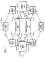
- FIG. 7is an exemplary embodiment of a control path featuring the interconnections between the I/O port module and servo modules.
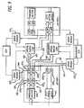
- FIG. 8is an exemplary embodiment of the I/O port module of FIGS. 6 and 7 illustrating a data propagation circuit and a control circuit.
- FIG. 9is an exemplary embodiment of multiple ports of I/O modules in communication with optical switches controlled by servo modules.
- FIG. 10is an exemplary embodiment of an I/O port configured as a test access port.
- FIG. 11is an exemplary embodiment of a servo module of the optical cross-connect system of FIG. 1 .
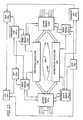
- FIG. 12is an exemplary block diagram of a redundant architecture of the optical cross-connect switching system of FIG. 1 .
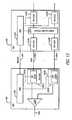
- FIG. 13is a block diagram illustrating an out-of-band signaling interface between an optical cross-connect switch and attached network equipment.
- FIG. 14is a block diagram illustrating a decentralized signaling interface between an optical cross-connect switch and attached network equipment.
- FIG. 15is a block diagram illustrating an unused protection connection and a first signaling means between an optical cross-connect switch and a client.
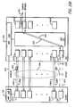
- FIG. 16Ais a block diagram illustrating a connection failure in a unidirectional link from a client into an optical cross-connect switch with the optical cross-connect signaling to the client to switch to protection.
- FIG. 16Bis a block diagram illustrating the operation of the protection connection between the optical cross-connect switch and the client for the connection failure illustrated in FIG. 16A in order to restore service.
- FIG. 17Ais a block diagram illustrating a connection failure a unidirectional link from an optical cross-connect switch to a client with the client signaling to the optical cross-connect to switch to protection.
- FIG. 17Bis a block diagram illustrating the operation of the protection connection between the optical cross-connect switch and the client for the connection failure illustrated in FIG. 17A in order to restore service.
- the exemplary embodiments of the present inventionrelate to a scalable, optical cross-connect switching system. These embodiments are not exclusive; rather, they merely provide a thorough understanding of the present invention. Well-known circuits are not set forth in detail in order to avoid unnecessarily obscuring the present invention.
- a “module”includes a substrate normally formed with any type of material or materials upon which components can be attached such as a printed circuit board or a daughter card for example.
- a “component”include an optical switch, a processing unit (e.g., Field Programmable Gate Array “FPGA”, digital signal processor, general microprocessor, application specific integrated circuit “ASIC”, etc.), couplers and the like.
- a “coupler”is a component that performs a bridging operation on an input light signal by splitting that light signal into two or more output light signals. Each module features one or more interfaces to transport information over a link.
- a “link”is broadly defined as one or more information-carrying mediums that establish a communication pathway such as, for example, optical fiber, electrical wire, cable, bus traces, wireless channels and the like.
- Informationis data, address, and/or control in any representative signaling format such as light signals (e.g., light pulses or photons).
- the present inventionprovides methods, apparatus and systems to provide protection against failures between the interconnection of client network equipment and optical cross-connect switching systems.
- the optical cross-connect switching system 100comprises three basic units: a switch subsystem 110 , a switch control subsystem 120 and an input/output (I/O) subsystem 130 .
- the modular architecture of the switch subsystem 110by a method of having replaceable optical switch cores, provides for switch subsystem maintenance in the event of failure within the switch subsystem 110 . It is conceivable that further modularity could be achieved by having replaceable subsections within, thus providing for switch matrix maintenance in the event of failure within a switch matrix itself.
- the modular architecture of both the switch control subsystem 120 and the I/O subsystem 130each handling a small number of I/O ports in the system 100 , provides scalability to the optical cross-connect switching system 100 .
- additional I/O portsmay be subsequently added to the optical cross-connect switching system 100 by adding or removing input/output (I/O) port modules (described below).
- the switch subsystem 110includes optical switches for routing light signals.
- the optical switches forming the switch subsystem 110are micro-machined mirrors; however, it is contemplated that other switch fabrics may be used such as liquid crystal technology:
- the I/O subsystem 130receives external light signals 140 and transfers these signals to the switch subsystem 110 .
- the switch control subsystem 120controls the configuration of the switch subsystem 110 (e.g., mirror orientation) and performs certain monitoring functions.
- the interconnectivity between the switch subsystem 110 , the switch control subsystem 120 and the I/O subsystem 130includes redundancy so that no equipment failures would cause complete disablement of the system 100 .
- the optical cross-connect switching system 100is a matrix-based optical cross-connect with associated I/O port modules. More specifically, the optical cross-connect switching system 100 is collectively formed by a plurality of platforms 205 , 206 and 207 in communication with each other, although the implementation of the switching system 100 as a single platform is another embodiment.
- each platform 205 , 206 and 207includes a frame 210 (e.g., a rack) that physically supports I/O port modules forming the I/O subsystem 130 as well as servo modules, servo control modules and/or network control modules of the switch control subsystem 120 .
- the modulesare arranged either horizontally or vertically within each platform 205 , 206 and 207 and can be individually removed or installed without interfering with immediately adjacent modules.
- the frame 210may also physically support one or more optical switch cores, which may also generally be referred to as “switch fabric,” of the switch subsystem 110 .
- the first platform 205comprises (i) a plurality of I/O port modules 215 associated with the I/O subsystem 130 of FIG. 1 , (ii) a plurality of servo modules 225 and a management control subsystem (MCS) 235 associated with switch control subsystem 120 of FIG. 1 , and (iii) a first (primary) optical switch core 240 associated with switch subsystem 110 of FIG. 1 .
- the second platform 206comprises a plurality of additional I/O port modules 245 , a plurality of (redundant) servo modules 250 , a management control subsystem 255 , and a second (redundant) optical switch core 260 .
- the third platform 207comprises a plurality of servo modules 265 that control various mirrors of the first and second optical switch cores 240 and 260 , which correspond to additional ports associated with I/O port modules 245 . Additionally, a light path test signal generator(s), a light path signal monitor(s), circuit breakers and/or alarm visual indication 270 may be located within the third platform 207 . For clarity, the elements forming the first platform 205 are described since these elements may be found in the second and/or third platforms 206 and 207 .
- the first optical switch core 240includes a first optical switch matrix 241 and a second optical switch matrix 242 .
- These matrices 241 and 242are collectively positioned to route light signals 250 between a port of a source I/O port module 215 s (“s” is a positive whole number) and a port of a destination I/O port module 215 d (“d” is a positive whole number), both modules located in any of the platforms 205 , 206 and 207 as shown in detail in FIG. 3 .
- a two-bounce routing techniqueis shown, it is contemplated that other light routing techniques may be used including a three-bounce routing technique in which an a second bounce mirror 202 optionally shown in FIG. 3 is positioned to assist in routing light signals from one optical switch matrix to another.
- each of the optical switch matrices 241 and 242includes multiple arrays 300 of micro-machined mirrors.
- Each mirrore.g., mirror 310
- both the first and second optical switch matrices 241 and 242include Q micro-machined mirrors, where “Q” is less than or equal to the maximum number of I/O ports that can be supported by the optical cross-connect switching system 100 .
- Qis greater than or equal to 64 but less than or equal to 1152 (64 ⁇ Q ⁇ 1152).
- the present inventionis not limited to any maximum number of mirrors or I/O ports. It is contemplated, however, that the number of mirrors employed within the first and second optical switch matrices 241 and 242 may differ.
- the plurality of I/O port modules 215features two groups 216 and 217 of I/O port modules.
- Each groupsuch as group 216 or 217 for instance, includes up to seventy-two (72) quad-port I/O port modules as shown in FIG. 5 that receive power from one or more power supply modules denoted herein as “PSM”.
- PSMpower supply modules
- the components forming an I/O port moduleis described below and shown in FIGS. 8 and 9 .
- each I/O port modulesuch as I/O port module 215 s for example, features an external interface 400 for a plurality of I/O ports 410 (e.g., four I/O ports).
- An I/O port 410features a duplex socket that is adapted to receive a duplex pair of optical fiber links, one optical fiber link routes a light signal to the I/O port 410 while the other routes light signals from the I/O port 410 .
- the I/O port module 215 supon receiving an incoming light signal over an optical fiber link 420 , performs a bridging operation by splitting the incoming light signal into multiple (two or more) bridged light signals for routing to the first and second optical switch cores 240 and 260 .
- the bridged light signalsare routed through an internal optical interface 425 featuring optical fiber ribbon links 430 and 440 .
- the “optical fiber ribbon links”are ribbon cables having multiple optical fiber lines (e.g., two lines from each I/O port).
- the first optical switch core 240provides a primary optical path.
- the second optical switch core 260provides a redundant optical path in the event the first optical switch core 240 is not operating properly.
- the optical switch cores 240 and 260route the bridged light signals to a selected port of a destination I/O port module (e.g., I/O port module 215 d ) via optical fiber ribbon links 450 and 460 .
- the I/O port module 215 sUpon receiving light signals from both the first and second optical switch cores 240 and 260 , the I/O port module 215 s provides small percentage optical tap signals of the received light paths to the respective servo modules, which in turn determine light signal quality.
- the respective servo moduleswill convey light signal quality for each respective light path to the I/O port module, using a digital protocol over an electrical communication link 505 to the I/O port module as shown in FIG. 7 .
- the I/O port module 215 swill in turn, determine (i.e. select) which light signal has the higher signal quality and outputs that signal via interface 400 . In most cases, the signal quality of the two light paths presented to the I/O port module will be of the same signal quality and may have a relatively low optical loss of approximately seven decibels (7 dB) or less.
- each servo module 225is configured to receive optical tap signals from one or more I/O port modules.
- servo module 225 iis configured to receive optical tap signals via link 500 from I/O port module 215 s . These optical tap signals provide feedback to indicate a percentage of the bridged light signals and also allow for light to be injected under certain conditions.
- the servo module 225 iprovides mirror control signals over link 510 to the first optical switch core 240 .
- the mirror control signalsare routed via a unique communication path to an optical switch (e.g., a micro-machined mirror) and are associated with the port of the I/O port module 215 s through which the incoming light signal was routed.
- the mirror control signalsare used for proper adjustment of the physical orientation of the mirror.
- the I/O port module 215 dprovides optical tap signals over link 530 to servo module 225 j .
- the servo module 225 jprovides mirror control signals via link 540 to the first optical switch core 240 .
- the mirror control signalsare routed via a unique communication path to a micro-machined mirror associated with a selected port of the I/O port module 215 d from which the light signal would be output.
- the servo module 225 jdetermines the light signal quality and conveys light signal quality information for each light path using a digital protocol over (electrical) link 535 . Thereafter, the I/O port module 215 d chooses the selected port (i.e. port having the best light signal quality).
- optical tap signals, mirror control signals and light signal quality informationwhich are routed over links 500 , 510 , 530 , 540 , 505 and 535 , are used by servo modules 225 i and 225 j for adjustment of the physical orientation of mirrors to make a connection between I/O port module 215 s and 215 d .
- I/O port modules 215 s and 215 dalso transfer optical tap signals via links 520 and 550 , respectively. Similar to the above description, these optical tap signals establish the redundant optical path by altering the physical orientation of one or more micro-machined mirrors of the second optical switch core 260 using mirror control signals over links 560 and 570 and light signal quality information via links 525 and 555 .
- a substitute light signalmay be injected from the servo module 225 i via link 500 .
- An alignment lasermay be used as shown in FIG. 11 described below. This process of light substitution allows for connection establishment and verification when no input light is present to the I/O port module 215 s .
- the substitute light sourcecan be within the same wavelength range (e.g. 1100 nanometers “nm”—1700 nm) as the allowed input light signal range. In one embodiment, the light source or method of injection would be chosen to not interfere with attached equipment's select operational wavelength range. Choosing a different wavelength source on the servo module and/or a wavelength specific splitter and/or filter on the I/O port module could do this particular embodiment.
- the management control subsystem 235(see FIG. 2 ) enables communications between two or more servo modules placed within the same or different platforms.
- the management control subsystem 235includes at least one servo control module 236 and an optional network control module 238 .
- the servo control module (SCM) 236ensures communication between at least servo modules 225 i and 225 j that control mirrors associated with the first optical switch core 240 .
- the network control module (NCM) 238manages the execution of connection configurations for the whole cross-connect switching system and ensures communications between multiple servo control modules 236 and 237 .
- the same architectureis used to control optical switches within the second optical switch core 260 as shown.
- I/O port module 215 sincludes a data propagation circuit 600 for each I/O port and a control circuit 670 .
- I/O port module 215 sis configured with four I/O ports, four data propagation circuits are implemented on the I/O port module 215 s as represented. Only the data propagation circuit 600 for one of the I/O ports of I/O port module 215 , (e.g., i th I/O port) is shown in detail for clarity sake.
- the data propagation circuit 600comprises an optical switch 610 , a (passive) splitter 620 and a plurality of tap couplers 630 1 - 630 4 .
- the plurality of tap couplers 630 1 - 630 4correspond to the pairs of optical fibers found in optical fibber ribbon links 430 and 440 .
- the control circuit 670comprises a programmable memory 680 , a processing unit 685 and status identification components 690 .
- each port of the I/O port module 215 ssupports full-duplex communications.
- an incoming light signal 606 received over port 605is routed to the splitter 620 .
- the splitter 620effectively performs a bridging operation by splitting the incoming light signal 606 into bridged light signals 625 , which collectively have the same power level (energy) as the light signal 606 .
- the splitter 620is a 50/50 splitter
- the bridged light signals 625have equal power levels.
- splitter 620may produce bridged light signals 625 having disproportionate power levels.
- the bridged light signals 625are routed through the tap couplers 630 1 and 630 2 . Attached to servo module 225 j and servo module 225 i+1 via optical tap links 500 and 520 , the tap couplers 630 1 , and 630 2 are used to monitor the power level of light signals 635 and 636 propagating through optical fiber ribbon links 430 and 440 (referred to as “outgoing light signals”). This enables the servo modules 225 i and 225 i+l to verify the connectivity of the splitter 620 to optical fiber ribbon links 430 and 440 and to detect unacceptable variances in optical performance of the light signal.
- the tap couplers 630 1 and 630 2may separate the bridged light signals into signals having disproportionate power levels in order to maximize the power levels of the outgoing light signals propagating through optical fiber ribbon links 430 and 440 .
- the tap couplers 630 1 and 630 2may operate as 90/10 splitters, the outgoing light signals 635 and 636 have ninety (90%) of the total power level of the bridged light signal while the tap optical signals 640 and 641 have only ten percent (10%).
- tap couplers 630 3 and 630 4are configured to receive incoming light signal 650 and 655 via optical fiber ribbon links 430 and 440 , respectively.
- the tap couplers 630 3 and 630 4effectively separate the light signals 650 and 655 into corresponding pairs of light signals having disproportionate power levels (e.g., signals 661 , 662 and 663 , 664 ).
- Signals 662 and 664 having the lower power levelare provided to the servo module 225 i and servo module 225 i+1 via links 500 and 520 for monitoring the power levels of the light signals 661 and 663 , without the light signals 661 and 663 experiencing substantial signal degradation.
- the signals 662 and 664may be light signals that undergo O/E conversion at the I/O port module 215 s or at the servo modules 225 i and 225 i+1 as shown in FIG. 11 .
- the tap couplers 630 3 and 630 4are shown as 90/10 splitters; however, tap couplers 630 3 and 630 4 may be any selected ratio, including 50/50.
- the light signals 661 and 663are routed to the optical switch 610 of a destined I/O port.
- the control circuit 650 on the I/O port module 215 sdetermines which of the pair of light signals 661 and 663 has the best signal quality based on conveyed light signal quality information from the servo modules via links 505 and 525 as briefly described below. Parameters used to determine light signal quality include measured optical signal intensity/power, extinction ratio, and the like.
- the light signal quality information to the I/O port modulemay be conveyed as failed due to the servo module service operations, high bit error rate, an external light path has failed, and the like.
- the light signal 661 or 663 with the best signal qualityis output through the I/O port 605 .
- an I/O port of the I/O port module 215 smay be configured as a test access port.
- a “test access port”is an I/O port that is used for monitoring light signals routed through another port. Normally, the test access port receives a portion of the power level of a light signal routed through a selected optical switch (e.g., micro-machined mirror). For example, as shown in FIG.
- an I/O port 218 of the I/O port module 215is configured for coupling with a monitoring device 219 (e.g., a bit error rate “BER” monitor in combination with an optical-electrical “O/E” converter, etc.) to monitor a power level of a light signal routed to the i th I/O port from an optical switch.
- a monitoring device 219e.g., a bit error rate “BER” monitor in combination with an optical-electrical “O/E” converter, etc.
- the control circuit 670comprises the programmable memory 680 in communication with the processing unit 685 (e.g., FPGA).
- the programmable memory 680contains software and other information used by the processing unit 685 to provide selection of the best quality signal based on digital electrical signaling from servo module 225 i and servo module 225 i+1 over links 505 and 525 , respectively.
- programmable memory 680includes information used by the processing unit 685 to control the state of the status identification components 690 (e.g., light emitting diodes “LEDs”).
- the state of the status identification components 690identifies (1) whether each I/O port is operational and/or (2) whether the I/O port module is operational.
- the processing unit 685is further in communications with optical switches of each data propagation circuit employed in the I/O port module 215 s in order to receive switch status signals and provide switch control signals. As shown for clarity, processing unit 685 provides optical switch 610 with switch control signals for receiving switch status signals and selecting either light signal 661 or light signal 663 .
- the servo module 225 icomprises two separate modules in communication over connectors 705 and 790 . These separate modules are referred to as an “optical detector module” 700 and a “servo mirror control module” 750 .
- the optical detector module 700comprises a first processing unit 710 , memory 715 , a plurality of detection/modulation (DM) circuits 716 and status identification components 717 . As shown, the optical detector module 700 features sixteen (16) DM circuits 716 to support four (4) quad-port I/O port modules. Each DM circuit 716 includes an analog-to-digital (A/D) converter 720 , a laser 725 , optical-electrical (O/E) detectors 730 and 731 , and optional amplifiers 735 and 736 .
- A/Danalog-to-digital
- O/Eoptical-electrical
- the servo mirror control module 750comprises a second processing unit 755 , a memory 760 , a plurality of mirror signal detection and generation (SDG) circuits 761 , a third processing unit 775 and status identification components 795 .
- the SDG circuits 761correspond in number to the DM circuits 716 of the optical detector module 700 .
- Each SDG circuit 761features an A/D converter 765 , a digital-to-analog (D/A) converter 770 , hinge position sensors 780 - 781 and high voltage (HV) mirror drivers 785 - 786 .
- the optical detector module 700is removably coupled to the servo mirror control module 750 .
- This “hot swapping” of the optical detector module 700allows for repair or upgrade of the optical detector module 700 .
- Optical detector module 700receives optical tap (feedback) signals 640 and 662 from one or more I/O port modules (e.g., I/O port module 215 via link 500 ) and can transmit optical control signals 726 from the laser 725 for alignment of light signals transferred between two I/O port modules.
- the optical tap signal 640is based on an input light signal that is routed to the switch fabric.
- the O/E detectors 730 and 731are coupled to tap couplers 630 , and 6303 of FIGS. 8-9 . More specifically, the O/E detectors 730 and 731 are configured to detect incoming, optical tap signals 640 and 662 , convert the optical tap signals 640 and 662 into corresponding electrical control signals measuring a power level of the outgoing light signal, and optionally route the electrical control signals to corresponding amplifiers 735 and 736 . The (amplified) electrical control signals are provided to the A/D converter 720 . The A/D converter 720 converts the electrical control signals into measured power sense signals 644 of a digital form.
- the measured power sense signals 644are provided to the first processing unit 710 .
- the first processing unit 710may perform a number of operations based on the electrical control signals such as threshold crossing, LOS integration, input/output power ratio analysis and the like. Software and other information necessary for performing these operations may be obtained from the memory 715 by the first processing unit 710 .
- memory 715can be non-volatile memory such as non-volatile random access memory, electrically erasable programmable read only memory (EEPROM) and the like.
- the optical detector module 700includes multiple status identification components 717 (e.g., light emitting diodes “LEDs”).
- a first LED 718identifies whether any operational faults associated with the servo module 225 i have occurred.
- a second LED 719indicates when the optical detector module 700 is in service.
- the servo mirror control module 750comprises the second processing unit 755 that is coupled to both the first processing unit 710 and the third processing unit 775 .
- the second processing unit 755receives information representative of the measured power sense signals from the first processing unit 710 via connectors 705 and 790 .
- the second processing unit 755further receives information representative of measured power sense signals for the light signal at a targeted I/O port. This information is provided by the SCM 236 over link 580 via the third processing unit 775 . This assists in reducing errors in adjusting the torsional flexures of the mirrors.
- the second processing unit 755Upon receipt of these measured power readings, the second processing unit 755 controls a particular SDG circuit corresponding to a mirror associated with the I/O port over which the tapped light signal was routed. The control involves slight mirror orientation adjustments if the power level readings differ substantially.
- a first hinge position sensor 780senses a position of a mirror via link 510 from the first optical switch core 240 .
- the sensed position signalis routed to the A/D converter 765 , which is subsequently placed in a digital format before routing to the second processing unit 755 .
- the second processing unit 755transfers mirror control signals to the D/A converter 770 .
- the mirror control signalsare routed to HV driver 785 and applied to a selected mirror of the first optical switch core in order to adjust the amount of torsional flexure along a first dimensional plane (e.g., X-axis). This is accomplished to minimize the loss experienced by the light signal.
- a second hinge position sensor 781senses a position of a mirror for the first optical switch core along a second dimensional plane (e.g., Y-axis).
- the sensed position signalis routed to the A/D converter 765 , which is subsequently placed in a digital format before routing to the second processing unit 755 .
- the second processing unit 755transfers mirror control signals to the D/A converter 770 .
- the mirror control signalsare routed to HV driver 786 and are applied to the selected mirror of the first optical switch core in order to adjust the amount of torsional flexure along the second dimensional plane.
- hinge position sensors 780 and 781are described in PCT application entitled “Micromachined Members Coupled for Relative Rotation By Torsional Flexure Hinges” (International Publication No. WO 00/13210) published on or around Mar. 9, 2000.
- the second processing unit 755receives information representative of the measured power sense signals associated with the optical tap signal 662 that has been analyzed by the first processing unit 710 .
- the optical tap signal 662is based on an output light signal being routed from an I/O port.
- the third processing unit 775receives information associated with the measured power sense signals from a source I/O port as reported by SCM 236 over link 580 .
- FIG. 12a block diagram of an alternative embodiment of the architecture of the optical cross-connect switching system of FIG. 1 is shown which includes redundant protection capabilities. Redundancy is desired in order to increase the reliability of such an optical cross-connect switching system. Aside from the I/O port modules, all other modules are duplicated to obtain the desired redundancy. Thus, it is necessary for light signals from a source I/O port module 215 d to be routed to, a destination I/O port module 215 d through two optical paths, namely a primary optical path 800 using a first optical switch core 240 and a redundant optical path 810 using a second optical switch core 260 .
- a servo module 225 iis connected to both the source I/O port module 215 , and the first optical switch matrix (not shown) of the first optical switch core 240 .
- the servo module 225 icontrols the physical orientation of a mirror of the first optical switch matrix that corresponds to the source I/O port module 215 s .
- the servo module 225 ineeds to communicate with other servo modules such as servo module 225 j .
- a servo control moduleSCM is implemented to support such communications, possibly through a time-slot switching arrangement.
- the SCMs 2361 - 2362are also duplicated so that each servo module 225 is connected to at least two SCMs 236 1 - 236 2 .
- the primary optical path 800remains intact because communications between the servo modules 225 i and 225 j are maintained via redundant SCM 237 1 .
- the transferis accomplished by temporarily halting the adjustment of (i.e. freezing) the mirrors inside the first optical switch core 240 while control is transferred from SCM 236 , to SCM 237 1 .
- the SCMs 236 1 and 237 1 associated with the first optical switch core 240are in communication via a network control modules (NCMs) 238 1 and 238 2 for example.
- NCMsnetwork control modules
- a servo module 225 i+lis connected to both the source I/O port module 215 s and one or more mirror(s) of a first optical switch matrix (not shown) of the second optical switch core 260 .
- Another servo module 225 j+lis connected to both the destination I/O port module 215 d and one or more mirror(s) of a second optical switch matrix (not shown) of the second optical switch core 260 . The orientation of these mirrors produces the redundant optical path 810 .
- a SCM 2362may be implemented with a dedicated time-slot switching arrangement in order to support continuous communications between the servo module and another redundant servo module associated with the destination I/O port module.
- the SCM 236 2is also duplicated so that each servo module 225 i+1 and 225 j +l is connected to at least two SCMs 236 2 and 237 2 .
- the redundant optical path 810is maintained even when one of the SCMs 236 2 and 237 2 fails.
- the SCMs 236 2 and 237 2 associated with the second optical switch core 260communicate via the first NCM 238 1 and the second NCM 238 2 , respectively.
- the second NCM 238 2is in communication with the first NCM 238 1 to allow all SCMs and servo modules to communicate for coordination of the primary optical path 800 and the redundant optical path 810 .
- optical cross-connect switchesOXCs
- An optical cross-connect switchcan also be referred to herein as optical cross-connect switching system, OXC, or optical cross-connect. Attached to the optical cross-connect switches in a telecommunications network is one or more pieces of attached network equipment (ANE) 1302 .
- ANEattached network equipment
- the attached network equipment (ANE) 1302includes telecommunication network devices such as a wavelength division multiplexed (WDM) line terminals, SONET add/drop multiplexers, internet protocol (IP) routers, additional optical cross-connect switches and Asynchronous Transfer Mode (ATM) switches which are also collectively referred to as client equipment.
- WDM line terminalsprovide interconnection between sites and are also terminating devices included in SONET add/drop multiplexers, internet protocol (IP) routers, or Asynchronous Transfer Mode (ATM) switches.
- the present inventionestablishes a signaling interface between the optical cross-connects 1300 and attached network equipment (ANE) 1302 .
- ANEattached network equipment
- One reasonis to allow the other network equipment in the telecommunications network to provision connections through the OXC. It is very desirable to allow other equipment to set up a connection through the OXC in an automated manner, rather than manually provisioning such connections.
- Another reasonis to provide real-time performance monitoring and other management information to the optical cross-connects 1300 from the attached network equipment 1302 . By providing a signaling interface where performance information is provided back to the optical cross-connects 1300 , expensive monitoring elements are not needed inside the optical cross-connects 1300 and costs are saved.
- the attached network equipmentusually already have electronic components for monitoring signals, such as optical-to-electrical-to-optical converters (OEOs or O/E/Os), in order to extract such information from optical signals.
- OEOsoptical-to-electrical-to-optical converters
- the electronics for monitoringdo not need to be duplicated inside the optical cross-connects 1300 when they are already provided in the attached network equipment 1302 .
- the optical cross-connects 1300can obtain the real-time performance monitoring and other management information from the other network equipment that is attached to the optical cross-connects 1300 through a signaling channel.
- Another reason to establish a signaling interfaceis so that the attached network equipment 1302 can obtain monitoring and other management information real-time from the optical cross-connects 1300 .
- the optical cross-connects 1300can similarly monitor received optical signals on its input ports and provide information back to the attached network equipment 1302 .
- the optical cross-connects 1300only monitor the optical power of the received optical signals by tapping off a small percentage of the energy of the optical signal and use optical-to-electrical converters (OEs or O/Es) to determine the optical power without using O/E/Os.
- OEs or O/Esoptical-to-electrical converters
- FIG. 13illustrates a block diagram of an out-of-band signaling interface between an optical cross-connect switch 1300 and attached network equipment 1302 .
- the signaling interfaceis realized by using an out-of-band communication channel over a network 1304 which may also be referred to as an out-of-band signaling channel.
- In-band communication channelsare those used by the optical cross-connect switch 1300 to switch data signals on the one or more data signals lines 1306 A- 1306 N.
- An out-of-band communication channelis a communication channel other than that used by the optical cross-connect switch 1300 to switch its data signals on the data lines 1306 A- 1306 N.
- the in-band communication channels used to switch data signals on the data lines 1306 A- 1306 N by the optical cross-connect switch 1300are light signals, also referred to as photonic signals or optical signals, that are carried in optical fibers.
- the data lines 1306 A- 1306 Nare not used for the signaling interface because these lines carry high-bandwidth signals.
- To convert optical signals in the optical domain into electrical signals in the electrical domain to extract signaling informationis a very expensive process. Indeed, a major reason for using an all-optical cross-connect is to avoid converting signals from the optical domain to the electrical domain.
- the out-of-band signaling channelis provided on a network 1304 such as a LAN, a MAN, the internet or other WAN.
- Each of the data lines 1360 A- 1306 Nis bi-directional to provide duplex data communication channels.
- the data lines 1306 A- 1306 Nin one embodiment include at least two optical fibers for data flow in each direction between the optical cross-connect switch and the attached network equipment 1402 to provide full duplex data communication channels.
- each of the data lines 1306 A- 1306 Nis a single optical fiber to provide bi-directional signal flow in both directions and can be full or half duplex data communication over a single optical fiber. Full duplex is accomplished over a single optical fiber by transmitting and detecting signals in the single optical fiber at each end.
- the network 1304also provides a bi-directional out-of-band signaling channel so that signals can be received and transmitted in each direction between the optical cross-connect switch and the attached network equipment 1402 and other network equipment coupled to the network 1304 .
- the out-of-band signaling channelcan be either full duplex or half duplex in providing bi-directional data communication.
- Data signals from the optical cross-connect switch 1300 on the data lines 1306 A- 1306 Nare coupled into the attached network equipment 1302 .
- the data lines 1306 A- 1306 Nare a light transmission media, such as optical fibers, coupled between the optical cross-connect switch 1300 and the attached network equipment 1302 to carry or transport the light pulses or photon pulses of the data signals there-between. That is, the attached network equipment 1302 is coupled or attached to the optical cross-connect switch 1300 to accept data signals transported over the one or more data lines 1306 A- 1306 N.
- Data signals from the attached network equipment (ANE) 1302 on the data lines 1306 A- 1306 Nare coupled into the optical cross-connect switch 1300 .
- ANEattached network equipment
- the optical cross-connect switch 1300is coupled or attached to the attached network equipment 1302 to accept data signals transported over the one or more data lines 1306 A- 1306 N.
- the optical cross-connect switch 1300includes the network management controller (NMC) 1310 (also previously referred to herein as a network control module (NCM)), one or more I/O port cards 1314 A- 1314 N and 1315 A- 1315 N, and the optical switch fabric 1312 .
- the optical switch fabricgenerates optical paths therein in order to cross-connect (also referred to as route or switch) optical signals from an I/O port card on the input side to an I/O port card on the output side.
- the optical pathsare bi-directional in that the optical signal can flow in either direction with the optical path coupled to either an input port or an output port of a port card.
- I/O port cardscan also be referred to as line cards, port cards, or I/O port modules as previously used herein.
- Each of the one or more I/O port cards 1314 A- 1314 N and 1315 A- 1315 N of the optical cross-connect switch 1300includes an optical input port and an optical output port to couple to the optical fibers of the full duplex data lines 1306 A- 1306 N.
- Port cards 1314can also include some simple monitoring functions by tapping off a small percentage of the energy of the optical signal and converting it into an electrical signal using an inexpensive O/E.
- port cards 1314do not need a full-fledged receiver for extensive monitoring of parameters such as a bit error rate or the presence of a particular frame because the signaling interface of the present invention is provided in order to acquire such information from other network equipment.
- the attached network equipment 1302includes a network management controller 1320 and one or more I/O port cards 1321 A- 1321 N (also referred to as line cards or herein previously as I/O port modules).
- Each of the one or more I/O port cards 1321 A- 1321 Nincludes an optical-electrical-optical converter 1322 A- 1322 N on its data input ports to couple to optical fibers of the data lines 1306 A- 1306 N.
- the one or more optical-electrical-optical converters 1322 A- 1322 Nfirst convert the optical signals on the data lines 1306 A- 1306 N into electrical signals and then convert the electrical signals into optical signals.
- the one or more optical-electrical-optical converters 1322 A- 1322 Ncan be used for a number of reasons including to generate electrical signals to monitor the optical signal as well as to amplify (i.e. regenerate) low level incoming optical signals.
- the one or more optical-electrical-optical converters 1322 A- 1322 Nprovide information regarding the optical signals in electrical form which is tapped for monitoring purposes as the electrical signals 1323 A- 1323 N.
- the electrical signals 1323 A- 1323 Nmay include information from other sources of the respective port card 1315 A- 1315 N that may be of relevance to the optical cross-connect switch.
- the one or more optical-electrical-optical converters 1322 A- 1322 N and their electrical signalswere originally used in the attached network equipment 1302 to facilitate its functionality and monitor its performance and not provide feedback to an optical cross-connect switch.
- the electrical signals 1323 A- 1323 Nare coupled into the network management controller (NMC) 1320 of the attached network equipment 1302 .
- the electrical signals 1323 A- 1323 N, or a representation thereofare signaled back to the optical cross-connect switch 1300 over the out-of-band signaling channel on the network 1304 .
- the electrical signals 1323 A- 1323 N, or a representation thereofare transmitted from the network management controller 1320 in the attached network equipment 1302 to the network management controller 1310 in the optical cross-connect switch 1300 .
- the attached network equipment 1302signals to the optical cross-connect switch 1300 .
- the optical cross-connect switch 1300can signal to the attached network equipment 1302 over the out-of-band signaling channel.
- optical-electrical-optical converters 1322 A- 1322 Nare expensive and as a result of being already available in the attached network equipment 1302 , they are not needed in the optical cross-connect switch 1300 if the signaling interface of the present invention is provided. This can provide considerable cost savings when purchasing optical cross-connect switches 1300 .
- the attached network equipment 1302 that is coupled to the optical cross-connect switch 1300is a WDM line terminal 1302 which also includes a wave division multiplexer/demultiplexer 1324 along with the network management controller 1320 and the one or more port cards 1321 A- 1321 N with the optical-electrical-optical converters 1322 A- 1322 N.
- the wave division multiplexer/demultiplexer 1324couples to a pair of optical fibers on one end to carry wave divisioned multiplexed signals 1326 in each direction for full duplex communication and one or more pairs of optical fibers on an opposite end to couple to the I/O port cards 1321 A- 1321 N.
- the wave division multiplexer/demultiplexer 1324multiplexes multiple light signals received from respective optical fibers in one direction into a wave division multiplexed signal 1326 having multiple light signals of different wavelengths carried over one optical fiber.
- the wave division multiplexer/demultiplexer 1324demultiplexes a wave division multiplexed signal 1326 in an opposite direction having multiple light signals of different wavelengths carried over one optical fiber into multiple light signals for transmission to the optical cross-connect switch 1300 over the data lines 1306 A- 1306 N.
- the wave division multiplexed signal 1326provides greater data bandwidth and channel capacity over an optical fiber.
- the network connection to the network 1304 for the out-of-band signaling channelis an Ethernet, an RS 232 or other similar connection connecting together the network management controllers (NMCs) (also previously referred to as a network control module (NCM)) of the optical cross-connect switch 1300 and the attached network equipment 1302 .
- NMCsnetwork management controllers
- NCMnetwork control module
- the out-of-band signaling channelis provided over the network 1304 , other network equipment or monitoring stations can receive information and transmit information or control signals over the out-of band signaling channel regarding the network, the network equipment and the optical network components connected to the network.
- management of the networkcan be facilitated regarding the optical cross-connect 1300 , the attached network equipment 1302 , and other network equipment using the out-of-band signaling channel.
- the out-of-band signaling channel over the networkcan be considered a centralized signaling interface.
- FIG. 14a block diagram of a decentralized signaling interface between an optical cross-connect switch 1400 and attached network equipment 1402 is illustrated.
- the decentralized signaling interfaceis provided by one or more dedicated signal lines 1404 A- 1404 N between the optical cross-connect switch 1400 and the attached network equipment 1402 .
- the one or more dedicated signal lines 1404 A- 1404 Ncan be formed by using low-cost multimode (MM) optical fibers or by using low cost electrical wire links.
- MMlow-cost multimode
- the one or more dedicated signal lines 1404 A- 1404 Nreplaces the out-of-band signaling channel of the network 1304 .
- the out-of-band signaling channel of the network 1304provided signals regarding switching each of the optical signals on multiple communication channels
- one dedicated signal line 1404provides information regarding switching of optical signals on one communication channel.
- the centralized signaling between the between the optical cross-connect switch 1400 and the attached network equipment 1402was performed by the centralized NMCs 1310 and 1320 at a central control level.
- decentralized signalingis performed by the I/O port cards (also referred to as line cards or herein previously as I/O port modules) at a line-card level which is a much lower level than the centralized NMC level.
- the optical cross-connect switch 1400includes the network management controller (NMC) 1310 , one or more I/O port cards 1414 A- 1414 N (also referred to as line cards, port cards and I/O port modules), and the optical switch fabric 1312 .
- NMCnetwork management controller
- I/O port cards 1414 A- 1414 N and 1415 A- 1415 N of the optical cross-connect switch 1400includes an optical input port and an optical output port.
- Each of the one or more port cards 1414 A- 1414 Nfurther may include optical-electrical converters (O/E) 1416 A- 1416 N if the dedicated signal line is an optical fiber.
- O/Eoptical-electrical converters
- optical-electrical converters 1416 A- 1416 N of the optical cross-connect switchare much less expensive than optical-electrical-optical converters (O/E/O) that might otherwise be needed therein.
- Optical-electrical converters (O/E)are typically a fiber optic receiver module which includes a photodetector.
- the attached network equipment 1402includes one or more port cards 1421 A- 1421 N (also referred to as line cards).
- Each of the one or more port cards 1321 A- 1321 Nincludes an optical-electrical-optical converter 1322 A- 1322 N on its data input ports to couple to optical fibers of the data lines 1306 A- 1306 N.
- each of the one or more port cards 1321 A- 1321 Nfurther includes an electrical-optical converter (E/O) 1422 A- 1422 N to convert electrical signals 1423 A- 1423 N into optical signals.
- Electrical-optical converters (E/O)are typically a fiber optic transmitter module which include a semiconductor laser with control electronics.
- Optical-electrical-optical converters (O/E/O)are typically a combination of an O/E converter coupled together with an E/O converter.
- the attached network equipment 1402 that is illustrated coupled to the optical cross-connect switch 1400is a WDM line terminal 1402 .
- a WDM line terminal 1402also includes a wave division multiplexer 1324 along with the one or more port cards 1421 A- 1421 N with the optical-electrical-optical converters 1322 A- 1322 N.
- the one or more optical-electrical-optical converters 1322 A- 1322 Nfirst convert the optical signals on the data lines 1306 A- 1306 N into electrical signals and then convert the electrical signals into optical signals.
- the one or more optical-electrical-optical converters 1322 A- 1322 Nare tapped to provide information regarding the optical signals in electrical form on the electrical signals 1323 A- 1323 N.
- the port cards 1421 A- 1421 N of the attached network equipment 1402detect other relevant information and communicate it directly to the respective port cards 1414 A- 1414 N of the optical cross-connect switch 1400 over the dedicated signal lines 1404 A- 1404 N rather than signaling between the central NMCs 1310 and 1320 .
- port cards 1414 A- 1414 N of the optical cross-connect switch 1400can detect relevant information and communicate it directly to the respective port cards 1421 A- 1421 N of the attached network equipment 1402 over the dedicated signal lines 1404 A- 1404 N.
- the signaling interfacecan be used to enable fast network restoration through the optical cross-connect switch (OXC) in the event of network failures.
- Network failuresinclude signal failures such as a loss of signal (LOS) or signal degradation such as through a bit error rate (BER) or other commonly know optical failure mechanisms.
- Attached network equipment (ANE)can detect failures in real time by using its O/E/Os and convey this information to the optical cross-connect switch over the signaling interface so that it can perform network restoration.
- the optical cross-connect switchis typically without O/E/Os and may not be able to detect the failure due to the otherwise relatively simple monitoring usually found within an optical cross-connect switch.
- ANEattached network equipment
- OXCoptical cross-connect switch
- the optical cross-connect switchcan signal to the attached network equipment to set specific parameters therein. For example during setting up a connection, the optical cross-connect switch may ask the attached equipment to adjust its transmitter power level.
- Another use for the signaling interfaceis to allow attached network equipment (ANE) to request a connection through the optical cross-connect switch (OXC).
- the optical cross-connect switch (OXC)sets up the connection and informs the attached network equipment (ANE) when its available.
- the signaling interfacecould be provided by one spare fiber facility for N working facilities between the attached equipment and the OXC. If bone of these N facilities fails, the signaling channel is used by both devices to switch connections from the failed facility to the spare facility.
- the present inventionprovides against connection or link failures between the interconnection of client equipment and optical network equipment such as an optical cross-connect switch.
- the present inventiondecouples the connection protection that is provided between client equipment and the optical cross-connect switch from the optical network equipment protection and that which may be provided by a network of optical cross-connects switches to handle failures of links and nodes inside the network. This is important because differing protection used inside the network from a connection protection used between the client and the OXC provides increased reliability. Additionally, optical network protection provided between client equipment and optical cross-connect switches can use a more complex protection mechanism which uses bandwidth more efficiently.
- connection protectionis particularly complex when the optical network equipment in question is an all-optical cross-connect switch.
- An all-optical cross-connect switchdoes not terminate the optical signals and convert them into electrical signals using optical-to-electrical converters on the input side.
- an all-optical cross-connect switchdoes not necessarily incorporate electrical-to-optical (E/O) converters (i.e. transmitters or lasers) that it can turn ON and OFF to provide signaling to the other end.
- E/Oelectrical-to-optical
- the present inventionprovides connection protection for optical network equipment including optical cross-connect switches and all-optical cross-connect switches.
- client equipment 1502is coupled to an optical cross-connect switch (OXC) 1504 by means of the optical connections or working optical links 1506 .
- client equipment 1502include internet protocol (IP) routers, Synchronous Optical Network (SONET) terminals, add/drop multiplexers as well as additional optical cross-connect switches and other optical networking equipment.
- IPinternet protocol
- SONETSynchronous Optical Network
- the protection provided by the present inventionis facilitated by one or more extra full duplex connections between the client equipment 1502 and the optical cross-connect switch 1504 referred to herein as a protect connections, one of which is protect connection 1508 .
- a signaling means for signaling purposes between the client equipment 1502 and the optical cross-connect switch 1504is provided, such as the signaling channel 1514 which can be an out-of-band communication channel over the network 1304 which was previously discussed.
- the optical links 1506include N optical links 1506 A- 1506 N and N optical links 1506 A′- 1506 N′.
- the N optical links 1506 A- 1506 Nare for ordinarily transporting optical signals from the client 1502 to the optical cross-connect switch 1504 between ports 1521 A- 1521 N and ports 1531 A- 1531 N.
- the N optical links 1506 A′- 1506 N′are for transporting optical signals from the optical cross-connect switch 1504 to the client 1502 between ports 1521 A- 1521 N and ports 1531 A- 1531 N.
- the optical links 1506 A- 1506 N and 1506 A′- 1506 N′are typically provided by fiber optic cables.
- the N optical links 1506 A- 1506 N and N optical links 1506 A′- 1506 N′can also be referred to as working links.
- Working linksordinarily transport or propagate optical signals between the client 1502 and the optical cross-connect switch 1504 when there is no connection failure.
- a protect connectioncan provide bi-directional transport of optical signals such as the protect connection 1508 which includes an optical link 1518 and an optical link 1518 ′.
- the optical link 1518is for communicating signals from the client 1502 to the optical cross-connect switch 1504 between port 1522 and port 1532 .
- the optical link 1518 ′is for communicating signals from the optical cross-connect switch 1504 to the client 1502 between port 1522 and port 1532 .
- the optical links 1518 and 1518 ′are typically provided by fiber optic cables.
- the optical link 1518 and the optical link 1518 ′can also be referred to as protection links.
- the protection links 1518 and 1518 ′atypically bi-directionally transport optical signals between the client 1502 and the optical cross-connect switch 1504 . That is, the protection links typically bi-directionally transport optical signals between the client 1502 and the optical cross-connect switch 1504 only when there is a connection failure in one of the working links. While two optical links have been disclosed, only a single optical link need be used to provide bi-directional transport of optical signals between the client 1502 and the optical cross-connect switch 1504 in certain cases.
- the present inventionprovides M:N protection between the client equipment 1502 and the optical cross-connect switch 1504 . That is for every N working I/O ports between the client 1502 and the optical cross-connect switch 1504 having N pairs of working links 1506 there-between between, there are M (where M is greater than or equal to one) additional I/O port(s) each being dedicated as a protect connection.
- the protect connection 1508is an example of one protect connection with it being obvious that protect connection 1508 can be duplicated M times.
- an automatic protection switching (APS) protocolis required to signal the failure, and transfer or switch the connection from the failed link to one of the M protect connections.
- the client equipment 1502includes a network management controller (NMC) 1520 , N input/output (I/O) ports 1521 A- 1521 N, and M (M being greater than or equal to one) extra I/O ports for every N I/O ports 1521 A- 1521 N.
- I/O port 1522is an example of one of the extra M I/O ports for every N I/O ports 1521 A- 1521 N which is a spare protection port for the client equipment 1502 .
- the N I/O ports 1521 A- 1521 Ncouple to the N working links 1506 to communicate with the client 1502 .
- the extra I/O port 1522couples to the protection links or protection connection 1508 .
- the N I/O ports and the extra I/O port(s) of the client 1502are typically provided by I/O port cards.
- the NMC 1520couples to the signaling channel 1514 .
- Various signaling meanscan be used including the signaling channel 1514 which is an out-of-band signaling channel, for example an Ethernet, or an in-band signaling channel as previously discussed.
- the N I/O ports 1521 A- 1521 N of the clientare also referred to herein as working ports or client ports.
- the M extra I/O ports of the clientare also referred to as a protection ports.
- the optical cross-connect 1504includes a network management controller (NMC) 1530 , the optical switch fabric 1312 , N I/O ports 1531 A- 1531 N, M extra I/O ports (I/O port 1532 being an example of one of the M extra I/O ports) for every N I/O ports 1531 A- 1531 N, at least one additional I/O port 1541 A- 1541 M for coupling to at least one network.
- NMCnetwork management controller
- the at least one additional I/O port 1541 A- 1541 M for coupling to at least one networkdiffers little from the N I/O ports 1531 A- 1531 N but for the connection to the at least one network.
- one of the N I/O ports 1531 A- 1531 Ncan be utilized to couple to a network connection when not needed for connection to a client.
- the M extra I/O ports (I/O port 1532 being an example of one of the M extra I/O ports) for every N I/O ports 1531 A- 1531 Nacts as a protection port for the optical cross-connect switch 1504 .
- the N I/O ports 1531 A- 1531 Ncouple to the N working links 1506 .
- the M extra I/O ports(I/O port 1532 being an example) couple to the protection links or protect connections (such as protect connection 1508 ).
- the N I/O ports 1531 A- 1531 N, the M extra I/O ports, and the at least one additional I/O port 1541 A- 1541 M of the optical cross-connect switch 1504are typically provided by I/O port cards which may be referred to as working port cards, protection port cards, and network port cards respectively.
- the N I/O ports 1531 A- 1531 N of the optical cross-connectare also referred to as working ports or client ports because they couple to one or more clients.
- the at least one additional I/O port 1541 A- 1541 M for coupling to at least one network respectivelyare also referred to as network port(s) because of their connectivity to a network.
- the M extra I/O ports (I/O port 1532 being an example of one of the M extra I/O ports) of the optical cross-connectare also referred to as protect ports.
- the NMC 1530 of the optical cross-connect switch 1504 and the NMC 1520 of the client 1502couple to the signaling channel 1514 using signaling interfaces to transceive connection failure signals.
- dedicated signaling lines(such as shown in FIG. 14 ) may be used between the N I/O ports 1531 A- 1531 N of the optical cross-connect switch 1594 and the N I/O ports 1521 A- 1521 N of the client 1502 to transceive or bi-directionally transport connection failure signals.
- the working link of the pair of working links without the connection failure coupled between the N I/O ports 1531 A- 1531 N and the N I/O ports 1521 A- 1521 Nis used to transceive or bi-directionally transport connection failure signals.
- a connection failurecan be caused by failure in one of the working links 1506 between the client 1502 and the optical cross-connect switch 1504 .
- a connection failurecan be caused by a failure in one of the N I/O ports 1521 A- 1521 N in the client 1502 or one of the N I/O ports 1531 A- 1531 N in the optical cross-connect switch 1504 .
- either of the connection failure mechanismswill be referred to herein as a connection failure or link failure.
- a connection failureincludes signal failure conditions such as a loss of signal (LOS) or signal degrade conditions such as through a bit error rate (BER) threshold crossings or other commonly know optical failure mechanisms.
- LOSloss of signal
- BERbit error rate
- the optical switch fabric 1312establishes a pair of optical paths 1551 and 1552 between its port 1531 A and 1541 B.
- the optical cross-connect switch 1504cross-connects signals between I/O port 1531 A (also referred to as Port X) and I/O port 1541 B (also referred to as Port Y) such that there is a full duplex connection between the client 1502 and the network 1550 over the pair of optical links 1506 A and 1506 A′.
- the protection connection 1508is provided between the ports 1522 and 1532 of the client 1502 and the optical cross-connect switch 1504 respectively.
- a link failureoccurs in one of the links 1506 in the optical connection from the client 1504 to the optical cross-connect switch 1504 .
- the link 1506 Ais illustrated having the link failure 1602 in this case. This may be caused by damage to an optical fiber providing the optical connection or in a component in a port card of the client, such as a transmitter, or a port card of the optical cross-connect switch 1504 . For whatever reason, assume that signals from the client 1504 are not cross-connected through the optical cross-connect switch to the network 1550 over the link 1506 A.
- port 1531 A in the receive side of the optical cross-connect 1504detects the connection failure due to a lack of an incoming signal with or without using an optical-electrical-optical converter (O/E/O).
- Port 1531 Acan detect a signal loss without using an optical-electrical-optical converter (O/E/O) by tapping the optical signal and measuring the signal power or by determining if specific patterns are non-existent in the signal indicating a signal loss.
- This detection of signal losscan generally be referred to as detecting or sensing a connection failure and may generally be referred to as being performed by a sensor in the N I/O ports 1531 A- 1531 N or N I/O ports 1521 A- 1521 N.
- the optical cross-connect switch 1504Upon detecting a connection failure in one of the links 1506 A- 1506 N, the optical cross-connect switch 1504 needs to signal the client 1502 as to which link has the connection failure.
- a portitself or through the NMC 1530 , can signal from the optical cross-connect switch 1504 to the client equipment 1502 that a connection failure has occurred.
- the optical cross-connect switch 1504can use the network 1514 illustrated in FIG. 15 to signal to the client 1502 that a connection failure has occurred in one of the links 1506 A- 1506 N.
- the network 1514is referred to as an out-of-band signaling channel and is an Ethernet for example.
- the portitself can signal to the respective port of the client equipment that a connection failure has occurred in one of the links 1506 A- 1506 N by terminating the signal propagation in the reverse direction over one of the links 1506 A′- 1605 N′.
- the respective port in the client equipmentdetects the termination of the signal propagation as a connection failure in the respective one of the links 1506 A′- 1506 N′ and attempts to similarly signal the optical cross-connect switch and then switches to the protection connection 1508 .
- Terminating the signal propagation over the reverse link of the respective link having the connection failureis referred to as an in-band signaling mechanism.
- a predetermined patternindicating signal loss on the link in the opposing direction, can be transmitted on the good link of the pair. Upon detecting the predetermined pattern, it is understood that a signal failure has occurred on the opposite link.
- dedicated signaling linkselectrical or optical such as the optical dedicated signaling links 1404 A- 1404 N previously described, between port cards of the optical cross connect and port cards of the client 1502 can be used to signal a connection failure.
- the port 1531 Aitself or through the NMC 1530 , signals from the optical cross-connect switch 1504 to the client equipment 1502 that the connection failure 1602 has occurred in link 1506 A as illustrated in FIG. 16 A.
- the optical cross-connect switch 1504 and the client 1502after being signaled, now know that a connection failure in link 1506 A has occurred.
- the optical cross-connect switch 1504 and the client 1502each switch from the pair of full duplex links 1506 A and 1506 A′ over to the protection connection 1508 and its pair of full duplex links 1518 and 1518 ′.
- the client 1502internally switches the connection from port 1521 A to its protection port 1522 .
- the optical cross-connect 1504internally switches the connection from port 1531 A to its protection port 1532 ending the optical paths 1551 and 1551 ′ and establishing optical paths 1651 and 1651 ′ respectively through the optical switch fabric 1312 between its protection port 1532 and port 1541 B.
- FIG. 17Aassume that a link failure occurs in one of the links 1506 in the optical connection from the optical cross-connect switch 1504 to the client 1502 .
- the link 1506 A′is illustrated having the link failure 1702 in this case. This may be caused by damage to an optical fiber providing the optical connection or in a component in a port card of the optical cross-connect switch 1504 or the client 1502 . Signals at the optical cross-connect switch 1504 that are supposed to be coupled to one of the links 1506 A′- 1506 N′ and to the client 1502 do not reach the client 1502 due to some connection failure.
- port 1521 A in the receive side of the client 1502detects the connection failure due to a lack of an incoming signal with or without using an optical-electrical-optical converter.
- Port 1521 Acan detect a signal loss with or without an optical-electrical-optical converter (O/E/O).
- O/E/Ooptical-electrical-optical converter
- connection failure 1702the port 1521 A, itself or through the NMC 1520 , signals from the client equipment 1502 to the optical cross-connect switch 1504 that the connection failure 1702 has occurred in link 1506 A′ as illustrated in FIG. 17 A.
- port 1521 Asignals to the NMC 1520 the connection failure 1702 has occurred on link 1506 A′.
- the NMC 1520 coupled to the network 1514signals to the NMC 1530 coupled to the network 1514 using the out-of-band signaling channel.
- the port 1521 Asignals over the good link 1506 A to the port 1531 A that the connection failure 1702 has occurred in link 1506 A′.
- the signal over the good link 1506 Acan be either a pre-determined pattern indicating a signal loss on the opposite link or simply a termination of the signals on the link. If signal termination is used, the port 1531 A detects the signal termination assuming that a connection failure has occurred and attempts to signal back to the client 1502 and switches to the protection port 1532 .
- the client 1502 and the optical cross-connect switch 1504after being signaled, now know that a connection failure in link 1506 A′ has occurred.
- the optical cross-connect switch 1504 and the client 1502each switch from the pair of full duplex links 1506 A and 1506 A′ over to the protection connection 1508 and its pair of full duplex links 1518 and 1518 ′.
- the client 1502internally switches the connection from port 1521 A to its protection port 1522 .
- the optical cross-connect 1504internally switches the connection from port 1531 A to its protection port 1532 ending the optical paths 1551 and 1551 ′ and establishing optical paths 1651 and 1651 ′ respectively through the optical switch fabric 1312 between its protection port 1532 and port 1541 B.
- connection failurescan occur in both respective pair of links between the ports of the client and the optical cross-connect switch.
- link 1506 Acan experience the connection failure 1602 while the link 1506 A′ can experience the connection failure 1702 at the same moment.
- the client 1502detects the connection failure 1602 , attempts to signal the optical cross-connect switch 1504 and switches over to the protect port 1522 .
- the optical cross-connect switch 1504also detects the connection failure 1702 , attempts to signal the client 1502 , and internally switches the connection from port 1531 A to its protection port 1532 ending the optical paths 1551 and 1551 ′ and establishing optical paths 1651 and 1651 ′ respectively through the optical switch fabric 1312 between its protection port 1532 and port 1541 B.
- the present inventionis thus described and has many advantages over the prior art.
- One advantage of the present inventionis that service interruption is minimized in an optical connection between client equipment and optical cross-connect switches by utilizing the protection mechanism of the present invention.
- Another advantage of the present inventionis that minimal change need be made to client equipment and an optical cross-connect switch in order to support the protection connection.
- Still another advantage of the present inventionis that the network protection provided by the present invention is independent of other protection that may be provided in the network such as by the equipment itself or other network protection mechanisms.
- the optical cross-connect switchhas been described and illustrated as coupling to one client and one network but can just as well couple to multiple clients and multiple networks and provide connection protection for optical connections between the multiple clients and optical network equipment.
- the connection protectioncan be provided for optical connections between other types of optical networking equipment and not just client equipment and optical cross-connect switches.
Landscapes
- Engineering & Computer Science (AREA)
- Computer Networks & Wireless Communication (AREA)
- Signal Processing (AREA)
- Optical Communication System (AREA)
Abstract
Description
Claims (60)
Priority Applications (5)
| Application Number | Priority Date | Filing Date | Title |
|---|---|---|---|
| US09/704,458US6882765B1 (en) | 1999-11-02 | 2000-11-01 | Connection protection between clients and optical cross-connect switches |
| EP00975577AEP1228660A1 (en) | 1999-11-02 | 2000-11-02 | Connection protection between clients and optical cross-connect switches |
| CA002389721ACA2389721A1 (en) | 1999-11-02 | 2000-11-02 | Connection protection between clients and optical cross-connect switches |
| PCT/US2000/030408WO2001033896A1 (en) | 1999-11-02 | 2000-11-02 | Connection protection between clients and optical cross-connect switches |
| AU13606/01AAU1360601A (en) | 1999-11-02 | 2000-11-02 | Connection protection between clients and optical cross-connect switches |
Applications Claiming Priority (8)
| Application Number | Priority Date | Filing Date | Title |
|---|---|---|---|
| US16293699P | 1999-11-02 | 1999-11-02 | |
| US17009599P | 1999-12-10 | 1999-12-10 | |
| US17009299P | 1999-12-10 | 1999-12-10 | |
| US17009499P | 1999-12-10 | 1999-12-10 | |
| US17009399P | 1999-12-10 | 1999-12-10 | |
| US18610800P | 2000-03-01 | 2000-03-01 | |
| US20042500P | 2000-04-28 | 2000-04-28 | |
| US09/704,458US6882765B1 (en) | 1999-11-02 | 2000-11-01 | Connection protection between clients and optical cross-connect switches |
Publications (1)
| Publication Number | Publication Date |
|---|---|
| US6882765B1true US6882765B1 (en) | 2005-04-19 |
Family
ID=27575030
Family Applications (1)
| Application Number | Title | Priority Date | Filing Date |
|---|---|---|---|
| US09/704,458Expired - Fee RelatedUS6882765B1 (en) | 1999-11-02 | 2000-11-01 | Connection protection between clients and optical cross-connect switches |
Country Status (5)
| Country | Link |
|---|---|
| US (1) | US6882765B1 (en) |
| EP (1) | EP1228660A1 (en) |
| AU (1) | AU1360601A (en) |
| CA (1) | CA2389721A1 (en) |
| WO (1) | WO2001033896A1 (en) |
Cited By (25)
| Publication number | Priority date | Publication date | Assignee | Title |
|---|---|---|---|---|
| US20020196499A1 (en)* | 2001-06-25 | 2002-12-26 | Jeroen Wellen | Method and system for multiplexed optical information transport |
| US20030120755A1 (en)* | 2001-12-20 | 2003-06-26 | Fatica Dino B. | Data communication apparatus with distributed traffic protection switching system |
| US20040047542A1 (en)* | 2002-03-27 | 2004-03-11 | Humair Raza | Alignment laser for use in cross-connects |
| US20040258349A1 (en)* | 2001-06-29 | 2004-12-23 | Ugo Cerato | Modular cross connect system with 3d-mems for optical telecommunication networks |
| US20050157643A1 (en)* | 2003-12-29 | 2005-07-21 | Worldcom, Inc. | Method and apparatus for sharing common capacity and using different schemes for restoring telecommunications networks |
| US20050185954A1 (en)* | 2004-02-23 | 2005-08-25 | Sadananda Santosh K. | Reroutable protection schemes of an optical network |
| US20050185956A1 (en)* | 2004-02-23 | 2005-08-25 | Adisorn Emongkonchai | Fast fault notifications of an optical network |
| US20050196168A1 (en)* | 2004-03-03 | 2005-09-08 | Fujitsu Limited | Optical connection switching apparatus and management control unit thereof |
| US20050223276A1 (en)* | 2001-12-21 | 2005-10-06 | Moller Hanan Z | Method for encoding/decoding a binary signal state in a fault tolerant environment |
| US20050232629A1 (en)* | 2004-03-30 | 2005-10-20 | Fujitsu Limited | Optical connection switching apparatus and management control unit thereof |
| US20070153763A1 (en)* | 2005-12-29 | 2007-07-05 | Rampolla Richard A | Route change monitor for communication networks |
| US20070280696A1 (en)* | 2006-05-30 | 2007-12-06 | Rogers Communications, Inc. | Master/slave multiple path optical switching device |
| US20080117806A1 (en)* | 2005-12-22 | 2008-05-22 | Huawei Technologies Co., Ltd. | Method and device for recovering a shared mesh network |
| US7436763B1 (en)* | 2002-07-31 | 2008-10-14 | Nortel Networks Limited | Data communication apparatus with a dual mode protection switching system |
| US20100316374A1 (en)* | 2009-06-15 | 2010-12-16 | Fiber Connections Inc. | Networked mapping function |
| US20120243864A1 (en)* | 2011-03-25 | 2012-09-27 | Fujitsu Limited | Optical communication device and optical communication method |
| US20150071634A1 (en)* | 2012-06-06 | 2015-03-12 | Techsys Insights | Client Grooming Interface |
| US8989591B2 (en) | 2012-06-06 | 2015-03-24 | Techsys Insights | Remote optical demarcation point |
| US20160323203A1 (en)* | 2015-04-28 | 2016-11-03 | Compass Electro Optical Systems Ltd. | Access and distribution router |
| US20170184674A1 (en)* | 2015-12-29 | 2017-06-29 | Eaton Corporation | Circuit interrupter diagnostic system |
| US10063336B1 (en)* | 2017-10-24 | 2018-08-28 | Ciena Corporation | Protected transponded services integrated with control plane switched services |
| KR20180113718A (en)* | 2017-04-07 | 2018-10-17 | 재단법인대구경북과학기술원 | System for recovery of optical signal |
| US20190045279A1 (en)* | 2017-08-03 | 2019-02-07 | Facebook, Inc. | Scalable switch |
| US10419116B2 (en)* | 2016-06-17 | 2019-09-17 | Finisar Corporation | Transceiver to transceiver digital optical commands |
| US20230216886A1 (en)* | 2020-06-24 | 2023-07-06 | Nokia Technologies Oy | Data storage |
Families Citing this family (5)
| Publication number | Priority date | Publication date | Assignee | Title |
|---|---|---|---|---|
| CA2418384A1 (en)* | 2002-02-06 | 2003-08-06 | Nippon Telegraph And Telephone Corporation | Optical network, optical cross-connect apparatus, photonic-ip network, and node |
| CN1222821C (en) | 2002-07-01 | 2005-10-12 | 华为技术有限公司 | Optical channel protector and method based on WDM layer |
| CN100484022C (en) | 2005-07-04 | 2009-04-29 | 华为技术有限公司 | System and method for improving communication reliability |
| CN104635334B (en)* | 2013-11-15 | 2017-09-12 | 华为技术有限公司 | A kind of 3D mems optical switches |
| CN109756797A (en)* | 2017-11-07 | 2019-05-14 | 阿里巴巴集团控股有限公司 | Double upper linked methods, optical network management equipment and optical transmission system |
Citations (140)
| Publication number | Priority date | Publication date | Assignee | Title |
|---|---|---|---|---|
| US3651392A (en) | 1968-11-12 | 1972-03-21 | Otto R Frisch | Bang-bang mirror position servomechanism controlling a laser scanning device for use in a track-following machine |
| US4365863A (en) | 1979-05-30 | 1982-12-28 | Le Materiel Telephonique Thomson-Csf | Optical switch for a very large number of channels |
| US4369523A (en) | 1979-06-19 | 1983-01-18 | Kokusai Denshin Denwa Co., Ltd. | Remote control system of an optical repeater |
| US4437190A (en) | 1978-11-08 | 1984-03-13 | Boris Rozenwaig | Device for switching signals by optical means and automatic switching units comprising said device |
| US4470154A (en) | 1980-12-19 | 1984-09-04 | Ricoh Company, Ltd. | Optical communication network |
| US4519670A (en) | 1982-03-02 | 1985-05-28 | Spinner Gmbh, Elektrotechnische Fabrik | Light-rotation coupling for a plurality of channels |
| US4530566A (en) | 1982-05-12 | 1985-07-23 | Bicc Public Limited Company | Optical fiber duplex coupler |
| US4563774A (en) | 1982-10-25 | 1986-01-07 | At&T Bell Laboratories | Address coded communication system |
| US4580873A (en) | 1983-12-30 | 1986-04-08 | At&T Bell Laboratories | Optical matrix switch |
| WO1986004205A1 (en) | 1985-01-10 | 1986-07-17 | British Telecommunications Public Limited Company | Optical networks |
| US4612670A (en) | 1984-05-16 | 1986-09-16 | General Dynamics Corporation | Electro-optical connection between electronic modules |
| WO1986005649A1 (en) | 1985-03-11 | 1986-09-25 | British Telecommunications Public Limited Company | Optical networks |
| US4634239A (en) | 1984-08-03 | 1987-01-06 | Gte Laboratories Incorporated | Multiple port optical fiber switch |
| US4797879A (en) | 1987-06-05 | 1989-01-10 | American Telephone And Telegraph Company At&T Bell Laboratories | Packet switched interconnection protocols for a star configured optical lan |
| US4817014A (en) | 1986-10-03 | 1989-03-28 | Endress U. Hauser Gmbh U. Co. | Digital correlator |
| US4843382A (en) | 1985-10-18 | 1989-06-27 | Kokusai Denshin Denwa Co., Ltd. | Method for monitoring a digital transmission line |
| US4856863A (en) | 1988-06-22 | 1989-08-15 | Texas Instruments Incorporated | Optical fiber interconnection network including spatial light modulator |
| US4859012A (en) | 1987-08-14 | 1989-08-22 | Texas Instruments Incorporated | Optical interconnection networks |
| US4886335A (en) | 1988-01-07 | 1989-12-12 | Furukawa Electric Co., Ltd. | Optical fiber switch system |
| US4903225A (en) | 1988-12-23 | 1990-02-20 | Ampex Corporation | High speed digital data correlator having a synchronous pipelined full adder cell array |
| WO1990014734A1 (en) | 1989-05-25 | 1990-11-29 | British Telecommunications Public Limited Company | Optical networks |
| US4982446A (en) | 1987-07-16 | 1991-01-01 | British Telecommunications | Bit synchronization for optical networks |
| US4984238A (en) | 1988-03-14 | 1991-01-08 | Fujitsu Limited | Method and apparatus for frame synchronization |
| WO1991001603A1 (en) | 1989-07-21 | 1991-02-07 | British Telecommunications Public Limited Company | Data transmission on optical networks |
| US5035482A (en) | 1989-04-06 | 1991-07-30 | Amp Incorporated | Optical switch |
| US5037173A (en) | 1989-11-22 | 1991-08-06 | Texas Instruments Incorporated | Optical interconnection network |
| US5157652A (en) | 1989-07-28 | 1992-10-20 | Hewlett-Packard Company | Measurement of characteristics of broadcast optical networks |
| US5216729A (en) | 1991-11-18 | 1993-06-01 | Harmonic Lightwaves, Inc. | Active alignment system for laser to fiber coupling |
| US5253274A (en) | 1992-04-15 | 1993-10-12 | International Business Machines Corporation | Means to differentiate between commands and data on a communications link |
| US5260819A (en) | 1990-06-16 | 1993-11-09 | Northern Telecom Limited | Digital telemetry system and method for fault detection in optical transmission system |
| US5299044A (en) | 1992-08-24 | 1994-03-29 | At&T Bell Laboratories | Ranging method for use in TDMA systems on tree-and-branch optical networks |
| US5349550A (en) | 1991-06-27 | 1994-09-20 | The United States Of America As Represented By The Secretary Of The Navy | Long sequence correlation coprocessor |
| US5355238A (en) | 1993-08-18 | 1994-10-11 | Swl Inc. | Method and apparatus for the monitoring and demarcation of synchronous optical networks |
| US5359683A (en) | 1993-06-10 | 1994-10-25 | Advanced Optronics, Inc. | 1×N electromechanical optical switch |
| WO1995019689A1 (en) | 1994-01-18 | 1995-07-20 | British Telecommunications Public Limited Company | Interconnected passive optical networks |
| US5440654A (en) | 1993-12-30 | 1995-08-08 | Raytheon Company | Fiber optic switching system |
| EP0674457A2 (en) | 1994-03-17 | 1995-09-27 | Fujitsu Limited | Switching equipment |
| US5477364A (en) | 1989-07-21 | 1995-12-19 | British Telecommunications Public Limited Company | Data transmission on optical networks |
| US5485300A (en) | 1993-08-04 | 1996-01-16 | Fujitsu Limited | Optical transmitter and power setting method in optical transmitters for use in optical networks |
| US5487120A (en) | 1994-02-09 | 1996-01-23 | International Business Machines Corporation | Optical wavelength division multiplexer for high speed, protocol-independent serial data sources |
| US5488862A (en) | 1993-10-18 | 1996-02-06 | Armand P. Neukermans | Monolithic silicon rate-gyro with integrated sensors |
| US5515361A (en) | 1995-02-24 | 1996-05-07 | International Business Machines Corporation | Link monitoring and management in optical star networks |
| US5521732A (en) | 1993-06-08 | 1996-05-28 | Nec Corporation | Optical wavelength selection control system in optical networks |
| US5521734A (en) | 1994-12-30 | 1996-05-28 | At&T Corp. | One-dimensional optical data arrays implemented within optical networks |
| US5524153A (en) | 1995-02-10 | 1996-06-04 | Astarte Fiber Networks, Inc. | Optical fiber switching system and method using same |
| US5535293A (en) | 1994-12-09 | 1996-07-09 | Buchin; Michael P. | High-speed electro-optical modulator, chopper, and multiplexer/demultiplexer |
| EP0721275A2 (en) | 1994-12-28 | 1996-07-10 | Nec Corporation | OAM controll system in an optical network |
| US5539328A (en) | 1993-07-02 | 1996-07-23 | Tandem Computers Incorporated | Termination for high frequency clock distribution path |
| US5570371A (en) | 1994-06-01 | 1996-10-29 | Nec Corporation | Path trace byte collecting circuit for synchronous optical networks |
| EP0752794A2 (en) | 1995-07-05 | 1997-01-08 | Fujitsu Limited | Cross-connect device for optical networks |
| EP0759681A2 (en) | 1995-08-18 | 1997-02-26 | Nippon Telegraph And Telephone Corporation | Optical cross-connect system |
| US5608735A (en) | 1995-09-20 | 1997-03-04 | Adtran, Inc. | Logical transform operator-based method and apparatus for extracting framing pattern from serial digital bit stream |
| US5629919A (en) | 1995-04-26 | 1997-05-13 | Matsushita Electric Industrial Co., Ltd. | Two plate-like beam splitting device |
| US5629790A (en) | 1993-10-18 | 1997-05-13 | Neukermans; Armand P. | Micromachined torsional scanner |
| WO1997024822A1 (en) | 1995-12-28 | 1997-07-10 | Mci Communications Corporation | Method and system for detecting optical faults within the optical domain of a fiber communication network |
| US5666487A (en) | 1995-06-28 | 1997-09-09 | Bell Atlantic Network Services, Inc. | Network providing signals of different formats to a user by multplexing compressed broadband data with data of a different format into MPEG encoded data stream |
| EP0802697A2 (en) | 1996-04-15 | 1997-10-22 | Fujitsu Limited | Optical transmission system |
| EP0809384A2 (en) | 1996-05-20 | 1997-11-26 | Nec Corporation | Network failure restoration method with different recovery performances for different signal groups |
| US5694389A (en) | 1995-02-24 | 1997-12-02 | Kabushiki Kaisha Toshiba | OFDM transmission/reception system and transmitting/receiving apparatus |
| US5699463A (en) | 1995-06-28 | 1997-12-16 | Hewlett-Packard Company | Mechanical fiber optic switch |
| US5719903A (en) | 1995-06-28 | 1998-02-17 | Motorola, Inc. | Method and apparatus for receiving symbols |
| US5727098A (en) | 1994-09-07 | 1998-03-10 | Jacobson; Joseph M. | Oscillating fiber optic display and imager |
| US5729527A (en) | 1995-12-29 | 1998-03-17 | Tellabs Operations, Inc. | Fault management in a multichannel transmission system |
| US5745274A (en) | 1995-12-27 | 1998-04-28 | Lucent Technologies Inc. | Maintenance of optical networks |
| EP0849906A2 (en) | 1996-12-19 | 1998-06-24 | Fujitsu Limited | Optical time division demultiplexing apparatus and demultiplexed signal switching method as well as optical time division multiplex transmission system |
| US5774604A (en) | 1996-10-23 | 1998-06-30 | Texas Instruments Incorporated | Using an asymmetric element to create a 1XN optical switch |
| US5781537A (en) | 1995-07-07 | 1998-07-14 | International Business Machines Corporation | Setting up, taking down and maintaining connections in a communications network |
| EP0857000A2 (en) | 1997-01-31 | 1998-08-05 | Nec Corporation | Optical transmission system |
| US5793746A (en) | 1996-04-29 | 1998-08-11 | International Business Machines Corporation | Fault-tolerant multichannel multiplexer ring configuration |
| US5825877A (en) | 1996-06-11 | 1998-10-20 | International Business Machines Corporation | Support for portable trusted software |
| US5828476A (en) | 1996-06-11 | 1998-10-27 | The Boeing Company | Dual rate, burst mode, radiation hardened, optical transceiver |
| WO1998054863A1 (en) | 1997-05-27 | 1998-12-03 | Ciena Corporation | Span management system for wavelength division multiplexed network |
| US5864643A (en) | 1996-12-20 | 1999-01-26 | E-Tek Dynamics, Inc. | Miniature 1XN electromechanical optical switch and variable attenuator |
| US5867289A (en) | 1996-12-24 | 1999-02-02 | International Business Machines Corporation | Fault detection for all-optical add-drop multiplexer |
| WO1999013656A1 (en) | 1997-09-08 | 1999-03-18 | Koninklijke Kpn N.V. | Interconnection system for optical networks |
| WO1999018751A1 (en) | 1997-10-03 | 1999-04-15 | Newbridge Networks Corporation | Multiple internetworking realms within an internetworking device |
| EP0910138A1 (en) | 1997-10-17 | 1999-04-21 | Lucent Technologies Inc. | Sub-carrier multiplexing in broadband optical networks |
| US5900968A (en) | 1996-02-23 | 1999-05-04 | Lucent Technologies Inc. | Method of fast gain control in WDM optical networks |
| US5903687A (en) | 1997-05-02 | 1999-05-11 | Neos Technologies, Inc. | M input port by N output port optical switching system |
| US5915063A (en) | 1997-01-15 | 1999-06-22 | Colbourne; Paul | Variable optical attenuator |
| EP0932069A1 (en) | 1998-01-27 | 1999-07-28 | Hewlett-Packard Company | Reversible optical isolator for optical networks and amplifier |
| WO1999040738A1 (en) | 1998-02-05 | 1999-08-12 | Koninklijke Kpn N.V. | Optical circuit for obtaining a monitor signal |
| US5942937A (en) | 1997-11-19 | 1999-08-24 | Advanced Micro Devices, Inc. | Signal detection circuit using a plurality of delay stages with edge detection logic |
| EP0938244A2 (en) | 1998-02-20 | 1999-08-25 | Fujitsu Limited | Optical wavelength multiplexing system having a redundant configuration |
| WO1999048323A2 (en) | 1998-03-17 | 1999-09-23 | Sonic Innovations, Inc. | Hearing aid fitting system |
| US5960132A (en) | 1997-09-09 | 1999-09-28 | At&T Corp. | Fiber-optic free-space micromachined matrix switches |
| US5963350A (en) | 1994-03-29 | 1999-10-05 | British Telecommunications Public Limited Company | Optical telecommunications network |
| US5970201A (en) | 1997-09-18 | 1999-10-19 | Lucent Technologies Inc. | Power regulation in optical networks |
| US5978113A (en) | 1997-08-29 | 1999-11-02 | Kight; William Dorsey | Apparatus for remote loopback testing and isolation of loss of signal failures within synchronous optical networks |
| EP0953854A1 (en) | 1998-04-29 | 1999-11-03 | Hewlett-Packard Company | Ring coupler for optical networks |
| WO1999063374A1 (en) | 1998-06-05 | 1999-12-09 | Herzel Laor | 1xN OPTICAL SWITCH |
| US6002818A (en) | 1997-12-05 | 1999-12-14 | Lucent Technologies Inc | Free-space optical signal switch arrangement |
| US6005993A (en) | 1997-11-14 | 1999-12-21 | Macdonald; Robert I. | Deflection optical matrix switch |
| US6008915A (en) | 1996-02-16 | 1999-12-28 | Lucent Technologies, Inc. | Method of identifying faults in WDM optical networks |
| US6009220A (en) | 1997-01-15 | 1999-12-28 | Chan; Chun-Kit | Surveillance system for passive branched optical networks |
| WO1999067666A1 (en) | 1998-06-05 | 1999-12-29 | Astarte Fiber Networks, Inc. | Mirror based fiber optic switch and control system |
| WO2000007945A1 (en) | 1998-08-06 | 2000-02-17 | Federalnoe Gosudarstvennoe Unitarnoe Predpriyatie 'issledovatelsky Tsentr Imeni M.V.Keldysha' | Method for processing mineralised water |
| WO1999059272A9 (en) | 1998-05-13 | 2000-03-02 | Telcordia Tech Inc | Method and apparatus for automated time domain monitoring in optical networks |
| WO2000013210A2 (en) | 1998-09-02 | 2000-03-09 | Xros, Inc. | Micromachined members coupled for relative rotation by torsional flexure hinges |
| US6047331A (en) | 1997-02-19 | 2000-04-04 | Massachusetts Institute Of Technology | Method and apparatus for automatic protection switching |
| US6046833A (en) | 1997-02-10 | 2000-04-04 | Optical Networks, Inc. | Method and apparatus for operation, protection, and restoration of heterogeneous optical communication networks |
| WO2000004671A9 (en) | 1998-07-20 | 2000-04-06 | Herzel Laor | Method and apparatus for identifying and tracking connections of communication lines |
| WO2000020899A2 (en) | 1998-09-15 | 2000-04-13 | Xros, Inc. | Flexible, modular, compact fiber optic switch |
| EP0994635A1 (en) | 1998-10-13 | 2000-04-19 | Nortel Networks Corporation | Method and apparatus for data transmission in synchronous optical networks |
| US6061482A (en) | 1997-12-10 | 2000-05-09 | Mci Communications Corporation | Channel layered optical cross-connect restoration system |
| WO2000030282A1 (en) | 1998-11-17 | 2000-05-25 | Templex Technology, Inc. | Code-based optical networks, methods, and apparatus |
| US6069924A (en) | 1997-02-21 | 2000-05-30 | Matsushita Electric Industrial Co., Ltd. | Differential detector with error correcting function |
| US6072612A (en) | 1997-08-08 | 2000-06-06 | Lucent Technologies, Inc. | WDM transmitter for optical networks using a loop-back spectrally sliced light emitting device |
| WO1999066354A3 (en) | 1998-06-05 | 2000-06-15 | Astarte Fiber Networks Inc | Planar array optical switch and method |
| WO1999063531A9 (en) | 1998-06-05 | 2000-07-27 | Herzel Laor | Optical switch for disk drive |
| US6097858A (en) | 1998-06-05 | 2000-08-01 | Astarte Fiber Networks, Inc. | Sensing configuration for fiber optic switch control system |
| US6097859A (en) | 1998-02-12 | 2000-08-01 | The Regents Of The University Of California | Multi-wavelength cross-connect optical switch |
| US6108311A (en) | 1996-04-29 | 2000-08-22 | Tellabs Operations, Inc. | Multichannel ring and star networks with limited channel conversion |
| GB2347570A (en) | 1999-03-03 | 2000-09-06 | Fujitsu Ltd | Multi-wavelength optical networks with wavelength redistribution |
| US6130876A (en) | 1997-09-24 | 2000-10-10 | At&T Corp | Method and apparatus for restoring a network |
| US6148124A (en) | 1998-11-20 | 2000-11-14 | Lucent Technologies | Wavelength division multiplexed optical networks |
| US6160821A (en) | 1997-11-05 | 2000-12-12 | Sony International (Europe) Gmbh | Synchronization of digital communication systems |
| US6185021B1 (en) | 1998-03-20 | 2001-02-06 | Lucent Technologies, Inc. | Cross-connecting optical translator array |
| US6188814B1 (en) | 1999-08-03 | 2001-02-13 | Lucent Technologies Inc. | Packaged microelectromechanical devices and systems |
| US6188810B1 (en) | 1999-03-03 | 2001-02-13 | Agilent Technologies, Inc. | Reversible ring coupler for optical networks |
| US6192172B1 (en) | 1999-08-09 | 2001-02-20 | Lucent Technologies Inc. | Optical wavelength-space cross-connect switch architecture |
| US6195402B1 (en) | 1996-09-25 | 2001-02-27 | Matsushita Electric Industrial Co., Ltd. | Pattern matching apparatus |
| US6198571B1 (en) | 1999-03-31 | 2001-03-06 | Afc Technologies Inc. | Computerized intelligent optical amplifier for multi-channel optical networks |
| US6207949B1 (en) | 1999-11-10 | 2001-03-27 | Telcordia Technologies, Inc. | Method and apparatus for stabilizing attenuators in optical networks |
| EP1087556A1 (en) | 1999-09-22 | 2001-03-28 | Lucent Technologies Inc. | Power splitter for optical networks |
| WO2001028136A1 (en) | 1999-10-12 | 2001-04-19 | Tellabs Operation Inc. | Prevention of lasing in a closed optical loop |
| US6222954B1 (en) | 1999-09-17 | 2001-04-24 | Light Bytes, Inc. | Fault-tolerant fiber-optical beam control modules |
| US6252689B1 (en) | 1998-04-10 | 2001-06-26 | Aircuity, Inc. | Networked photonic signal distribution system |
| WO2001050176A1 (en) | 2000-01-06 | 2001-07-12 | Polatis Limited | Optical fibre switching assembly |
| US6272154B1 (en) | 1998-10-30 | 2001-08-07 | Tellium Inc. | Reconfigurable multiwavelength network elements |
| US6278812B1 (en) | 1998-12-14 | 2001-08-21 | At&T Corporation | Protection schemes for mirror-failure in free-space micromachined optical switches |
| WO2001063803A1 (en) | 2000-02-22 | 2001-08-30 | Xros, Inc. | Simple, high-speed optical signal pattern and protocol detection |
| US6285809B1 (en) | 1999-11-19 | 2001-09-04 | Lynx Photonic Networks, Inc. | Wraparound optical switch matrix |
| US6295154B1 (en) | 1998-06-05 | 2001-09-25 | Texas Instruments Incorporated | Optical switching apparatus |
| WO2001071402A1 (en) | 2000-03-17 | 2001-09-27 | Xros, Inc. | Variable attenuation of free-space light beams |
| US6301402B1 (en) | 2000-03-02 | 2001-10-09 | Lucent Technologies, Inc. | Control arrangement for optical mechanical switches |
| US6317530B1 (en) | 1998-12-28 | 2001-11-13 | Lucent Technologies | Micro-opto mechanical multistage interconnection switch |
| US6400730B1 (en) | 1999-03-10 | 2002-06-04 | Nishan Systems, Inc. | Method and apparatus for transferring data between IP network devices and SCSI and fibre channel devices over an IP network |
| US6504963B1 (en)* | 1998-12-07 | 2003-01-07 | Sprint Communications Company L.P. | Optical fiber protection switch |
| US6735390B1 (en)* | 2000-10-31 | 2004-05-11 | Lucent Technologies Inc. | Method and apparatus for terminating optical links in an optical network |
- 2000
- 2000-11-01USUS09/704,458patent/US6882765B1/ennot_activeExpired - Fee Related
- 2000-11-02AUAU13606/01Apatent/AU1360601A/ennot_activeAbandoned
- 2000-11-02EPEP00975577Apatent/EP1228660A1/ennot_activeWithdrawn
- 2000-11-02CACA002389721Apatent/CA2389721A1/ennot_activeAbandoned
- 2000-11-02WOPCT/US2000/030408patent/WO2001033896A1/ennot_activeApplication Discontinuation
Patent Citations (156)
| Publication number | Priority date | Publication date | Assignee | Title |
|---|---|---|---|---|
| US3651392A (en) | 1968-11-12 | 1972-03-21 | Otto R Frisch | Bang-bang mirror position servomechanism controlling a laser scanning device for use in a track-following machine |
| US4437190A (en) | 1978-11-08 | 1984-03-13 | Boris Rozenwaig | Device for switching signals by optical means and automatic switching units comprising said device |
| US4365863A (en) | 1979-05-30 | 1982-12-28 | Le Materiel Telephonique Thomson-Csf | Optical switch for a very large number of channels |
| US4369523A (en) | 1979-06-19 | 1983-01-18 | Kokusai Denshin Denwa Co., Ltd. | Remote control system of an optical repeater |
| US4470154A (en) | 1980-12-19 | 1984-09-04 | Ricoh Company, Ltd. | Optical communication network |
| US4519670A (en) | 1982-03-02 | 1985-05-28 | Spinner Gmbh, Elektrotechnische Fabrik | Light-rotation coupling for a plurality of channels |
| US4530566A (en) | 1982-05-12 | 1985-07-23 | Bicc Public Limited Company | Optical fiber duplex coupler |
| US4563774A (en) | 1982-10-25 | 1986-01-07 | At&T Bell Laboratories | Address coded communication system |
| US4580873A (en) | 1983-12-30 | 1986-04-08 | At&T Bell Laboratories | Optical matrix switch |
| US4612670A (en) | 1984-05-16 | 1986-09-16 | General Dynamics Corporation | Electro-optical connection between electronic modules |
| US4634239A (en) | 1984-08-03 | 1987-01-06 | Gte Laboratories Incorporated | Multiple port optical fiber switch |
| WO1986004205A1 (en) | 1985-01-10 | 1986-07-17 | British Telecommunications Public Limited Company | Optical networks |
| US4897830A (en) | 1985-01-10 | 1990-01-30 | British Telecommunications, Public Limited Company | Optical networks |
| WO1986005649A1 (en) | 1985-03-11 | 1986-09-25 | British Telecommunications Public Limited Company | Optical networks |
| US4843382A (en) | 1985-10-18 | 1989-06-27 | Kokusai Denshin Denwa Co., Ltd. | Method for monitoring a digital transmission line |
| US4817014A (en) | 1986-10-03 | 1989-03-28 | Endress U. Hauser Gmbh U. Co. | Digital correlator |
| US4797879A (en) | 1987-06-05 | 1989-01-10 | American Telephone And Telegraph Company At&T Bell Laboratories | Packet switched interconnection protocols for a star configured optical lan |
| US4982446A (en) | 1987-07-16 | 1991-01-01 | British Telecommunications | Bit synchronization for optical networks |
| US4859012A (en) | 1987-08-14 | 1989-08-22 | Texas Instruments Incorporated | Optical interconnection networks |
| US4886335A (en) | 1988-01-07 | 1989-12-12 | Furukawa Electric Co., Ltd. | Optical fiber switch system |
| US4984238A (en) | 1988-03-14 | 1991-01-08 | Fujitsu Limited | Method and apparatus for frame synchronization |
| US4856863A (en) | 1988-06-22 | 1989-08-15 | Texas Instruments Incorporated | Optical fiber interconnection network including spatial light modulator |
| US4903225A (en) | 1988-12-23 | 1990-02-20 | Ampex Corporation | High speed digital data correlator having a synchronous pipelined full adder cell array |
| US5035482A (en) | 1989-04-06 | 1991-07-30 | Amp Incorporated | Optical switch |
| WO1990014734A1 (en) | 1989-05-25 | 1990-11-29 | British Telecommunications Public Limited Company | Optical networks |
| US5272556A (en) | 1989-05-25 | 1993-12-21 | British Telecommunications | Optical networks |
| US5477364A (en) | 1989-07-21 | 1995-12-19 | British Telecommunications Public Limited Company | Data transmission on optical networks |
| WO1991001603A1 (en) | 1989-07-21 | 1991-02-07 | British Telecommunications Public Limited Company | Data transmission on optical networks |
| US5157652A (en) | 1989-07-28 | 1992-10-20 | Hewlett-Packard Company | Measurement of characteristics of broadcast optical networks |
| US5037173A (en) | 1989-11-22 | 1991-08-06 | Texas Instruments Incorporated | Optical interconnection network |
| US5260819A (en) | 1990-06-16 | 1993-11-09 | Northern Telecom Limited | Digital telemetry system and method for fault detection in optical transmission system |
| US5349550A (en) | 1991-06-27 | 1994-09-20 | The United States Of America As Represented By The Secretary Of The Navy | Long sequence correlation coprocessor |
| US5216729A (en) | 1991-11-18 | 1993-06-01 | Harmonic Lightwaves, Inc. | Active alignment system for laser to fiber coupling |
| US5253274A (en) | 1992-04-15 | 1993-10-12 | International Business Machines Corporation | Means to differentiate between commands and data on a communications link |
| US5299044A (en) | 1992-08-24 | 1994-03-29 | At&T Bell Laboratories | Ranging method for use in TDMA systems on tree-and-branch optical networks |
| US5521732A (en) | 1993-06-08 | 1996-05-28 | Nec Corporation | Optical wavelength selection control system in optical networks |
| US5359683A (en) | 1993-06-10 | 1994-10-25 | Advanced Optronics, Inc. | 1×N electromechanical optical switch |
| US5539328A (en) | 1993-07-02 | 1996-07-23 | Tandem Computers Incorporated | Termination for high frequency clock distribution path |
| US5485300A (en) | 1993-08-04 | 1996-01-16 | Fujitsu Limited | Optical transmitter and power setting method in optical transmitters for use in optical networks |
| US5355238A (en) | 1993-08-18 | 1994-10-11 | Swl Inc. | Method and apparatus for the monitoring and demarcation of synchronous optical networks |
| US5629790A (en) | 1993-10-18 | 1997-05-13 | Neukermans; Armand P. | Micromachined torsional scanner |
| US5648618A (en) | 1993-10-18 | 1997-07-15 | Armand P. Neukermans | Micromachined hinge having an integral torsion sensor |
| US5488862A (en) | 1993-10-18 | 1996-02-06 | Armand P. Neukermans | Monolithic silicon rate-gyro with integrated sensors |
| US5440654A (en) | 1993-12-30 | 1995-08-08 | Raytheon Company | Fiber optic switching system |
| WO1995019689A1 (en) | 1994-01-18 | 1995-07-20 | British Telecommunications Public Limited Company | Interconnected passive optical networks |
| US5825949A (en) | 1994-02-09 | 1998-10-20 | International Business Machines Corporation | Optical wavelength division multiplexer for coupling to data sources and sinks, wherein at least two data sources and sinks operate with different communication protocols |
| US5487120A (en) | 1994-02-09 | 1996-01-23 | International Business Machines Corporation | Optical wavelength division multiplexer for high speed, protocol-independent serial data sources |
| EP0674457A3 (en) | 1994-03-17 | 1998-05-13 | Fujitsu Limited | Switching equipment |
| EP0674457A2 (en) | 1994-03-17 | 1995-09-27 | Fujitsu Limited | Switching equipment |
| US5963350A (en) | 1994-03-29 | 1999-10-05 | British Telecommunications Public Limited Company | Optical telecommunications network |
| US5570371A (en) | 1994-06-01 | 1996-10-29 | Nec Corporation | Path trace byte collecting circuit for synchronous optical networks |
| US5727098A (en) | 1994-09-07 | 1998-03-10 | Jacobson; Joseph M. | Oscillating fiber optic display and imager |
| US5535293A (en) | 1994-12-09 | 1996-07-09 | Buchin; Michael P. | High-speed electro-optical modulator, chopper, and multiplexer/demultiplexer |
| EP0721275A2 (en) | 1994-12-28 | 1996-07-10 | Nec Corporation | OAM controll system in an optical network |
| US5521734A (en) | 1994-12-30 | 1996-05-28 | At&T Corp. | One-dimensional optical data arrays implemented within optical networks |
| US5524153A (en) | 1995-02-10 | 1996-06-04 | Astarte Fiber Networks, Inc. | Optical fiber switching system and method using same |
| US5694389A (en) | 1995-02-24 | 1997-12-02 | Kabushiki Kaisha Toshiba | OFDM transmission/reception system and transmitting/receiving apparatus |
| US5515361A (en) | 1995-02-24 | 1996-05-07 | International Business Machines Corporation | Link monitoring and management in optical star networks |
| US5629919A (en) | 1995-04-26 | 1997-05-13 | Matsushita Electric Industrial Co., Ltd. | Two plate-like beam splitting device |
| US5699463A (en) | 1995-06-28 | 1997-12-16 | Hewlett-Packard Company | Mechanical fiber optic switch |
| US5666487A (en) | 1995-06-28 | 1997-09-09 | Bell Atlantic Network Services, Inc. | Network providing signals of different formats to a user by multplexing compressed broadband data with data of a different format into MPEG encoded data stream |
| US5719903A (en) | 1995-06-28 | 1998-02-17 | Motorola, Inc. | Method and apparatus for receiving symbols |
| EP0752794A2 (en) | 1995-07-05 | 1997-01-08 | Fujitsu Limited | Cross-connect device for optical networks |
| US5781537A (en) | 1995-07-07 | 1998-07-14 | International Business Machines Corporation | Setting up, taking down and maintaining connections in a communications network |
| EP0759681A2 (en) | 1995-08-18 | 1997-02-26 | Nippon Telegraph And Telephone Corporation | Optical cross-connect system |
| US5608735A (en) | 1995-09-20 | 1997-03-04 | Adtran, Inc. | Logical transform operator-based method and apparatus for extracting framing pattern from serial digital bit stream |
| US5892606A (en) | 1995-12-27 | 1999-04-06 | Lucent Technologies, Inc. | Maintenance of optical networks |
| US5745274A (en) | 1995-12-27 | 1998-04-28 | Lucent Technologies Inc. | Maintenance of optical networks |
| US5801863A (en) | 1995-12-27 | 1998-09-01 | Lucent Technologies Inc. | Maintenance of optical networks |
| WO1997024822A1 (en) | 1995-12-28 | 1997-07-10 | Mci Communications Corporation | Method and system for detecting optical faults within the optical domain of a fiber communication network |
| US5729527A (en) | 1995-12-29 | 1998-03-17 | Tellabs Operations, Inc. | Fault management in a multichannel transmission system |
| US6008915A (en) | 1996-02-16 | 1999-12-28 | Lucent Technologies, Inc. | Method of identifying faults in WDM optical networks |
| US5900968A (en) | 1996-02-23 | 1999-05-04 | Lucent Technologies Inc. | Method of fast gain control in WDM optical networks |
| EP0802697A2 (en) | 1996-04-15 | 1997-10-22 | Fujitsu Limited | Optical transmission system |
| US5793746A (en) | 1996-04-29 | 1998-08-11 | International Business Machines Corporation | Fault-tolerant multichannel multiplexer ring configuration |
| US6108311A (en) | 1996-04-29 | 2000-08-22 | Tellabs Operations, Inc. | Multichannel ring and star networks with limited channel conversion |
| EP0809384A2 (en) | 1996-05-20 | 1997-11-26 | Nec Corporation | Network failure restoration method with different recovery performances for different signal groups |
| US5825877A (en) | 1996-06-11 | 1998-10-20 | International Business Machines Corporation | Support for portable trusted software |
| US5828476A (en) | 1996-06-11 | 1998-10-27 | The Boeing Company | Dual rate, burst mode, radiation hardened, optical transceiver |
| US6195402B1 (en) | 1996-09-25 | 2001-02-27 | Matsushita Electric Industrial Co., Ltd. | Pattern matching apparatus |
| US5774604A (en) | 1996-10-23 | 1998-06-30 | Texas Instruments Incorporated | Using an asymmetric element to create a 1XN optical switch |
| EP0849906A2 (en) | 1996-12-19 | 1998-06-24 | Fujitsu Limited | Optical time division demultiplexing apparatus and demultiplexed signal switching method as well as optical time division multiplex transmission system |
| US5864643A (en) | 1996-12-20 | 1999-01-26 | E-Tek Dynamics, Inc. | Miniature 1XN electromechanical optical switch and variable attenuator |
| US5867289A (en) | 1996-12-24 | 1999-02-02 | International Business Machines Corporation | Fault detection for all-optical add-drop multiplexer |
| US5915063A (en) | 1997-01-15 | 1999-06-22 | Colbourne; Paul | Variable optical attenuator |
| US6009220A (en) | 1997-01-15 | 1999-12-28 | Chan; Chun-Kit | Surveillance system for passive branched optical networks |
| EP0857000A2 (en) | 1997-01-31 | 1998-08-05 | Nec Corporation | Optical transmission system |
| EP0857000A3 (en) | 1997-01-31 | 2000-08-09 | Nec Corporation | Optical transmission system |
| US6046833A (en) | 1997-02-10 | 2000-04-04 | Optical Networks, Inc. | Method and apparatus for operation, protection, and restoration of heterogeneous optical communication networks |
| US6374008B2 (en) | 1997-02-13 | 2002-04-16 | The Regents Of The University Of California | Multi-wavelength cross-connect optical switch |
| US6047331A (en) | 1997-02-19 | 2000-04-04 | Massachusetts Institute Of Technology | Method and apparatus for automatic protection switching |
| US6069924A (en) | 1997-02-21 | 2000-05-30 | Matsushita Electric Industrial Co., Ltd. | Differential detector with error correcting function |
| US5903687A (en) | 1997-05-02 | 1999-05-11 | Neos Technologies, Inc. | M input port by N output port optical switching system |
| WO1998054863A1 (en) | 1997-05-27 | 1998-12-03 | Ciena Corporation | Span management system for wavelength division multiplexed network |
| US6072612A (en) | 1997-08-08 | 2000-06-06 | Lucent Technologies, Inc. | WDM transmitter for optical networks using a loop-back spectrally sliced light emitting device |
| US5978113A (en) | 1997-08-29 | 1999-11-02 | Kight; William Dorsey | Apparatus for remote loopback testing and isolation of loss of signal failures within synchronous optical networks |
| WO1999013656A1 (en) | 1997-09-08 | 1999-03-18 | Koninklijke Kpn N.V. | Interconnection system for optical networks |
| US5960132A (en) | 1997-09-09 | 1999-09-28 | At&T Corp. | Fiber-optic free-space micromachined matrix switches |
| US5970201A (en) | 1997-09-18 | 1999-10-19 | Lucent Technologies Inc. | Power regulation in optical networks |
| US6130876A (en) | 1997-09-24 | 2000-10-10 | At&T Corp | Method and apparatus for restoring a network |
| WO1999018751A1 (en) | 1997-10-03 | 1999-04-15 | Newbridge Networks Corporation | Multiple internetworking realms within an internetworking device |
| US6081361A (en) | 1997-10-17 | 2000-06-27 | Lucent Technologies Inc. | Sub-carrier multiplexing in broadband optical networks |
| EP0910138A1 (en) | 1997-10-17 | 1999-04-21 | Lucent Technologies Inc. | Sub-carrier multiplexing in broadband optical networks |
| US6160821A (en) | 1997-11-05 | 2000-12-12 | Sony International (Europe) Gmbh | Synchronization of digital communication systems |
| US6005993A (en) | 1997-11-14 | 1999-12-21 | Macdonald; Robert I. | Deflection optical matrix switch |
| US5942937A (en) | 1997-11-19 | 1999-08-24 | Advanced Micro Devices, Inc. | Signal detection circuit using a plurality of delay stages with edge detection logic |
| US6002818A (en) | 1997-12-05 | 1999-12-14 | Lucent Technologies Inc | Free-space optical signal switch arrangement |
| US6061482A (en) | 1997-12-10 | 2000-05-09 | Mci Communications Corporation | Channel layered optical cross-connect restoration system |
| EP0932069A1 (en) | 1998-01-27 | 1999-07-28 | Hewlett-Packard Company | Reversible optical isolator for optical networks and amplifier |
| WO1999040738A1 (en) | 1998-02-05 | 1999-08-12 | Koninklijke Kpn N.V. | Optical circuit for obtaining a monitor signal |
| US6097859A (en) | 1998-02-12 | 2000-08-01 | The Regents Of The University Of California | Multi-wavelength cross-connect optical switch |
| EP0938244A2 (en) | 1998-02-20 | 1999-08-25 | Fujitsu Limited | Optical wavelength multiplexing system having a redundant configuration |
| WO1999048323A2 (en) | 1998-03-17 | 1999-09-23 | Sonic Innovations, Inc. | Hearing aid fitting system |
| US6185021B1 (en) | 1998-03-20 | 2001-02-06 | Lucent Technologies, Inc. | Cross-connecting optical translator array |
| US6252689B1 (en) | 1998-04-10 | 2001-06-26 | Aircuity, Inc. | Networked photonic signal distribution system |
| EP0953854A1 (en) | 1998-04-29 | 1999-11-03 | Hewlett-Packard Company | Ring coupler for optical networks |
| WO1999059272A9 (en) | 1998-05-13 | 2000-03-02 | Telcordia Tech Inc | Method and apparatus for automated time domain monitoring in optical networks |
| WO1999063531A9 (en) | 1998-06-05 | 2000-07-27 | Herzel Laor | Optical switch for disk drive |
| WO1999066354A3 (en) | 1998-06-05 | 2000-06-15 | Astarte Fiber Networks Inc | Planar array optical switch and method |
| US6097858A (en) | 1998-06-05 | 2000-08-01 | Astarte Fiber Networks, Inc. | Sensing configuration for fiber optic switch control system |
| WO1999067666A1 (en) | 1998-06-05 | 1999-12-29 | Astarte Fiber Networks, Inc. | Mirror based fiber optic switch and control system |
| US6295154B1 (en) | 1998-06-05 | 2001-09-25 | Texas Instruments Incorporated | Optical switching apparatus |
| WO1999063374A1 (en) | 1998-06-05 | 1999-12-09 | Herzel Laor | 1xN OPTICAL SWITCH |
| WO2000004671A9 (en) | 1998-07-20 | 2000-04-06 | Herzel Laor | Method and apparatus for identifying and tracking connections of communication lines |
| WO2000007945A1 (en) | 1998-08-06 | 2000-02-17 | Federalnoe Gosudarstvennoe Unitarnoe Predpriyatie 'issledovatelsky Tsentr Imeni M.V.Keldysha' | Method for processing mineralised water |
| WO2000013210A9 (en) | 1998-09-02 | 2000-08-31 | Xros Inc | Micromachined members coupled for relative rotation by torsional flexure hinges |
| WO2000013210A3 (en) | 1998-09-02 | 2000-06-15 | Xros Inc | Micromachined members coupled for relative rotation by torsional flexure hinges |
| US6392220B1 (en) | 1998-09-02 | 2002-05-21 | Xros, Inc. | Micromachined members coupled for relative rotation by hinges |
| WO2000013210A2 (en) | 1998-09-02 | 2000-03-09 | Xros, Inc. | Micromachined members coupled for relative rotation by torsional flexure hinges |
| WO2000020899A2 (en) | 1998-09-15 | 2000-04-13 | Xros, Inc. | Flexible, modular, compact fiber optic switch |
| WO2000020899A3 (en) | 1998-09-15 | 2000-07-20 | Xros Inc | Flexible, modular, compact fiber optic switch |
| EP0994635A1 (en) | 1998-10-13 | 2000-04-19 | Nortel Networks Corporation | Method and apparatus for data transmission in synchronous optical networks |
| US6147968A (en) | 1998-10-13 | 2000-11-14 | Nortel Networks Corporation | Method and apparatus for data transmission in synchronous optical networks |
| US6272154B1 (en) | 1998-10-30 | 2001-08-07 | Tellium Inc. | Reconfigurable multiwavelength network elements |
| WO2000030282A1 (en) | 1998-11-17 | 2000-05-25 | Templex Technology, Inc. | Code-based optical networks, methods, and apparatus |
| US6148124A (en) | 1998-11-20 | 2000-11-14 | Lucent Technologies | Wavelength division multiplexed optical networks |
| US6504963B1 (en)* | 1998-12-07 | 2003-01-07 | Sprint Communications Company L.P. | Optical fiber protection switch |
| US6278812B1 (en) | 1998-12-14 | 2001-08-21 | At&T Corporation | Protection schemes for mirror-failure in free-space micromachined optical switches |
| US6317530B1 (en) | 1998-12-28 | 2001-11-13 | Lucent Technologies | Micro-opto mechanical multistage interconnection switch |
| GB2347570A (en) | 1999-03-03 | 2000-09-06 | Fujitsu Ltd | Multi-wavelength optical networks with wavelength redistribution |
| US6188810B1 (en) | 1999-03-03 | 2001-02-13 | Agilent Technologies, Inc. | Reversible ring coupler for optical networks |
| WO2000052865A1 (en) | 1999-03-03 | 2000-09-08 | Fujitsu Limited | Optical networks |
| US6400730B1 (en) | 1999-03-10 | 2002-06-04 | Nishan Systems, Inc. | Method and apparatus for transferring data between IP network devices and SCSI and fibre channel devices over an IP network |
| US6198571B1 (en) | 1999-03-31 | 2001-03-06 | Afc Technologies Inc. | Computerized intelligent optical amplifier for multi-channel optical networks |
| US6188814B1 (en) | 1999-08-03 | 2001-02-13 | Lucent Technologies Inc. | Packaged microelectromechanical devices and systems |
| US6192172B1 (en) | 1999-08-09 | 2001-02-20 | Lucent Technologies Inc. | Optical wavelength-space cross-connect switch architecture |
| US6222954B1 (en) | 1999-09-17 | 2001-04-24 | Light Bytes, Inc. | Fault-tolerant fiber-optical beam control modules |
| EP1087556A1 (en) | 1999-09-22 | 2001-03-28 | Lucent Technologies Inc. | Power splitter for optical networks |
| WO2001028136A1 (en) | 1999-10-12 | 2001-04-19 | Tellabs Operation Inc. | Prevention of lasing in a closed optical loop |
| US6207949B1 (en) | 1999-11-10 | 2001-03-27 | Telcordia Technologies, Inc. | Method and apparatus for stabilizing attenuators in optical networks |
| US6285809B1 (en) | 1999-11-19 | 2001-09-04 | Lynx Photonic Networks, Inc. | Wraparound optical switch matrix |
| WO2001050176A1 (en) | 2000-01-06 | 2001-07-12 | Polatis Limited | Optical fibre switching assembly |
| WO2001063803A1 (en) | 2000-02-22 | 2001-08-30 | Xros, Inc. | Simple, high-speed optical signal pattern and protocol detection |
| US6301402B1 (en) | 2000-03-02 | 2001-10-09 | Lucent Technologies, Inc. | Control arrangement for optical mechanical switches |
| WO2001071402A1 (en) | 2000-03-17 | 2001-09-27 | Xros, Inc. | Variable attenuation of free-space light beams |
| US6735390B1 (en)* | 2000-10-31 | 2004-05-11 | Lucent Technologies Inc. | Method and apparatus for terminating optical links in an optical network |
Non-Patent Citations (19)
| Title |
|---|
| A. Himeno, R. Nagase, T. Ito, K. Kato and M. Okuno; Photonic Inter-Module Connector Using 8x8 Optical Switches for Near-Future Electronic Switching Systems; IEICE Transactions on Communications; E77-B(1994) Feb., No. 2, Tokyo, JP. |
| All Optical Regeneration, Simon, et al., 2000 IEEE pp. 53-54. |
| An Economic Analysis for Core Optical Transport Networks, Peter Wong & Mark Yin. |
| Experimental Study of Internet Stability and Backbone Failures, Craig Labovitz, Abha Ahuja, Farnam Jahanaian, 1999 IEEE, pp. 278-285. |
| Free-Space Micromachined Optical Switches with Submillisecond Switching Time for Large-Scale Optical Crossconnects, Lin, et al., 04/98, pp. 525-527. |
| Gustaffson, K. & Hok, B., A Batch-Processed Optical Scanner Proc. 12th Nordic Semiconductor, Meeting, Jevnaker (Oslo: Center for Industrial Research) pp. 282-285 (1986). |
| Gustaffson, K. & Hok, B., a Silicon Light Modulator, Journal of Physics E. Scientific Instruments 21, pp. 608-605 (1998). |
| Gustaffson, K. & Hok, B., Fiberoptic Switching and Multiplexing with a Micromechanical Scanning Mirror, Digest of Technical Papers 4th Int. Conf. on Solid State Sensors and Actuators (Tokyo: Institute of Electrical Engineers of Japan) pp. 212-215 (1987). |
| Laor, H., et al., Performance of a 576 x 576 optical cross connect, NFOEC-99. |
| Lin L.Y., et al., Free-Space Micromachined Optical-Switching Technologies and Architectures, OFC/100C '99, Feb. 21-26, 1999. |
| Lin, L.Y. et al.; "Micro-Electro-Mechanical Systems (MEMS) for WDM Optical-Crossconnect Networks", Milcom 1999; IEEE Miltary Communications Conf Proceedings; Atlantic City, NJ Oct. 31-Nov. 3, 1999; pp. 954-957. |
| Lin, L.Y., et al., Free-Space Micromachined Optical-Switching Technologies and Architectures, OFC/100C '99, Feb. 21-26, 1999. |
| Okamoto, S. et al.; "Optical Path Cross-Connect Node Architectures for Photonic Transport Network", Journal of Lightwave Technology, vol. 14, No. 6, Jun. 1996, pp. 1410-1422. |
| Operation and Maintenance for an All-Optical Transport Network, Bischoff, et al., 11/96, IEEE Communications Magazine, pp. 136-142. |
| Optical Networks: A Practical Perspective; Rajic Pamaswami & Kumar Sivarajan; Morgan Kaufmann Pub. 1998, Chapter 10, pp. 423-462. |
| Optical Networks: A Practical Perspective; Rajiv Ramaswami & Kumar Sivarajan; Morgan Kaufmann Pub. 1998, pp. 152-161. |
| The Optical Internet A New Network Architecture, Kaufman, et al., pp. 1-13. |
| The Photonic Switch Completes the Much-Vaunted All-Optical Network, Technology Investor, Chad White, Oct. 2000, pp. 28-31. |
| Types and Characteristics of SDH Network Protection Architectures; ITU-T Recommendation G.841 (10/98). |
Cited By (43)
| Publication number | Priority date | Publication date | Assignee | Title |
|---|---|---|---|---|
| US20020196499A1 (en)* | 2001-06-25 | 2002-12-26 | Jeroen Wellen | Method and system for multiplexed optical information transport |
| US7676156B2 (en)* | 2001-06-25 | 2010-03-09 | Alcatel-Lucent Usa Inc. | Method and system for multiplexed optical information transport |
| US7366413B2 (en)* | 2001-06-29 | 2008-04-29 | Marconi Communications S.P.A. | Modular cross connect system with 3D-MEMS for optical telecommunication networks |
| US20040258349A1 (en)* | 2001-06-29 | 2004-12-23 | Ugo Cerato | Modular cross connect system with 3d-mems for optical telecommunication networks |
| US20030120755A1 (en)* | 2001-12-20 | 2003-06-26 | Fatica Dino B. | Data communication apparatus with distributed traffic protection switching system |
| US7158477B2 (en)* | 2001-12-20 | 2007-01-02 | Nortel Networks Limited | Data communication apparatus with distributed traffic protection switching system |
| US7480821B2 (en)* | 2001-12-21 | 2009-01-20 | Agere Systems Inc. | Method for encoding/decoding a binary signal state in a fault tolerant environment |
| US20050223276A1 (en)* | 2001-12-21 | 2005-10-06 | Moller Hanan Z | Method for encoding/decoding a binary signal state in a fault tolerant environment |
| US20040047542A1 (en)* | 2002-03-27 | 2004-03-11 | Humair Raza | Alignment laser for use in cross-connects |
| US7072031B2 (en)* | 2002-03-27 | 2006-07-04 | Nortel Networks, Ltd. | Alignment laser for use in cross-connects |
| US7436763B1 (en)* | 2002-07-31 | 2008-10-14 | Nortel Networks Limited | Data communication apparatus with a dual mode protection switching system |
| US8155515B2 (en)* | 2003-12-29 | 2012-04-10 | Verizon Business Global Llc | Method and apparatus for sharing common capacity and using different schemes for restoring telecommunications networks |
| US20050157643A1 (en)* | 2003-12-29 | 2005-07-21 | Worldcom, Inc. | Method and apparatus for sharing common capacity and using different schemes for restoring telecommunications networks |
| US20090208201A1 (en)* | 2004-02-23 | 2009-08-20 | Adisorn Emongkonchai | Fast fault notifications of an optical network |
| US7831144B2 (en) | 2004-02-23 | 2010-11-09 | Dynamic Method Enterprises Limited | Fast fault notifications of an optical network |
| WO2005083499A1 (en)* | 2004-02-23 | 2005-09-09 | Intellambda Systems Inc. | Reroutable protection schemes of an optical network |
| US20050185956A1 (en)* | 2004-02-23 | 2005-08-25 | Adisorn Emongkonchai | Fast fault notifications of an optical network |
| US7474850B2 (en)* | 2004-02-23 | 2009-01-06 | Dynamic Method Enterprises Limited | Reroutable protection schemes of an optical network |
| US20050185954A1 (en)* | 2004-02-23 | 2005-08-25 | Sadananda Santosh K. | Reroutable protection schemes of an optical network |
| US7499646B2 (en) | 2004-02-23 | 2009-03-03 | Dynamic Method Enterprises Limited | Fast fault notifications of an optical network |
| US20050196168A1 (en)* | 2004-03-03 | 2005-09-08 | Fujitsu Limited | Optical connection switching apparatus and management control unit thereof |
| US20050232629A1 (en)* | 2004-03-30 | 2005-10-20 | Fujitsu Limited | Optical connection switching apparatus and management control unit thereof |
| US7813640B2 (en)* | 2004-03-30 | 2010-10-12 | Fujitsu Limited | Optical connection switching apparatus and management control unit thereof |
| US20080117806A1 (en)* | 2005-12-22 | 2008-05-22 | Huawei Technologies Co., Ltd. | Method and device for recovering a shared mesh network |
| US7787362B2 (en)* | 2005-12-22 | 2010-08-31 | Huawei Technologies Co., Ltd. | Method and device for recovering a shared mesh network |
| US20070153763A1 (en)* | 2005-12-29 | 2007-07-05 | Rampolla Richard A | Route change monitor for communication networks |
| US7630597B2 (en)* | 2006-05-30 | 2009-12-08 | Rogers Communications Inc. | Master/slave multiple path optical switching device |
| US20070280696A1 (en)* | 2006-05-30 | 2007-12-06 | Rogers Communications, Inc. | Master/slave multiple path optical switching device |
| US20100316374A1 (en)* | 2009-06-15 | 2010-12-16 | Fiber Connections Inc. | Networked mapping function |
| US20120243864A1 (en)* | 2011-03-25 | 2012-09-27 | Fujitsu Limited | Optical communication device and optical communication method |
| US9014558B2 (en)* | 2012-06-06 | 2015-04-21 | Techsys Insights | Client grooming interface |
| US8989591B2 (en) | 2012-06-06 | 2015-03-24 | Techsys Insights | Remote optical demarcation point |
| US20150071634A1 (en)* | 2012-06-06 | 2015-03-12 | Techsys Insights | Client Grooming Interface |
| US20160323203A1 (en)* | 2015-04-28 | 2016-11-03 | Compass Electro Optical Systems Ltd. | Access and distribution router |
| US20170184674A1 (en)* | 2015-12-29 | 2017-06-29 | Eaton Corporation | Circuit interrupter diagnostic system |
| US10656207B2 (en)* | 2015-12-29 | 2020-05-19 | Eaton Intelligent Power Limited | Circuit interrupter diagnostic system |
| US10419116B2 (en)* | 2016-06-17 | 2019-09-17 | Finisar Corporation | Transceiver to transceiver digital optical commands |
| KR20180113718A (en)* | 2017-04-07 | 2018-10-17 | 재단법인대구경북과학기술원 | System for recovery of optical signal |
| US20190045279A1 (en)* | 2017-08-03 | 2019-02-07 | Facebook, Inc. | Scalable switch |
| US10334330B2 (en)* | 2017-08-03 | 2019-06-25 | Facebook, Inc. | Scalable switch |
| US10063336B1 (en)* | 2017-10-24 | 2018-08-28 | Ciena Corporation | Protected transponded services integrated with control plane switched services |
| US20230216886A1 (en)* | 2020-06-24 | 2023-07-06 | Nokia Technologies Oy | Data storage |
| US12425451B2 (en)* | 2020-06-24 | 2025-09-23 | Nokia Technologies Oy | Data storage |
Also Published As
| Publication number | Publication date |
|---|---|
| EP1228660A1 (en) | 2002-08-07 |
| CA2389721A1 (en) | 2001-05-10 |
| AU1360601A (en) | 2001-05-14 |
| WO2001033896A1 (en) | 2001-05-10 |
Similar Documents
| Publication | Publication Date | Title |
|---|---|---|
| US6882765B1 (en) | Connection protection between clients and optical cross-connect switches | |
| US6650803B1 (en) | Method and apparatus for optical to electrical to optical conversion in an optical cross-connect switch | |
| US6571030B1 (en) | Optical cross-connect switching system | |
| US6792174B1 (en) | Method and apparatus for signaling between an optical cross-connect switch and attached network equipment | |
| US6597826B1 (en) | Optical cross-connect switching system with bridging, test access and redundancy | |
| JP3298514B2 (en) | Optical path switching apparatus, method of using the same, and optical ADM apparatus and optical cross-connect network apparatus using the optical path switching apparatus | |
| US7620323B2 (en) | Method and apparatus for interconnecting a plurality of optical transducers with a wavelength division multiplexed optical switch | |
| Doverspike et al. | Fast restoration in a mesh network of optical cross-connects | |
| US20140050471A1 (en) | Apparatus And Method For Providing Protection In A Passive Optical Network | |
| EP2211560A2 (en) | Customer premises optical network unit | |
| US7551851B2 (en) | System and method for bypassing a faulty node in an optical network | |
| WO2001039413A2 (en) | 1+1 fault protection in a network of optical cross-connect switching systems | |
| Chan et al. | A novel optical-path supervisory scheme for optical cross connects in all-optical transport networks | |
| CN214675520U (en) | Optical line protection devices and optical line network transmission equipment | |
| Lin et al. | Integrated signal monitoring and connection verification in MEMS optical crossconnects | |
| JP4369972B2 (en) | Subscriber premises optical line termination equipment | |
| Lee et al. | A novel supervisory scheme for OXC based on different time-delay recognition | |
| Hayashi et al. | Reliability of optical bi-directional path switched ring networks using MEMS-based redundant switching fabrics | |
| EP1354439A2 (en) | Optical communications network and node for forming such a network | |
| Zong et al. | Optical switching board implementing wavelength routing supervision for optical cross-connects in WDM OTN |
Legal Events
| Date | Code | Title | Description |
|---|---|---|---|
| AS | Assignment | Owner name:NORTEL NETWORKS CORPORATION, CANADA Free format text:ASSIGNMENT OF ASSIGNORS INTEREST;ASSIGNORS:ERICKSON, KENT;KALIGOTLA, SUBHASHINI;RAMASWAMI, RAJIV;REEL/FRAME:011797/0272 Effective date:20010508 | |
| AS | Assignment | Owner name:XROS, INC., CALIFORNIA Free format text:CORRECTIVE ASSIGNMENT TO CORRECT THE ASSIGNEE ADDRESS, PREVIOUSLY RECORDED AT REEL 011797, FRAME 0272;ASSIGNORS:ERICKSON, KENT;KALIGOTLA, SUBHASHINI;RAMASWAMI, RAJIV;REEL/FRAME:012787/0679 Effective date:20010508 | |
| FEPP | Fee payment procedure | Free format text:PAYOR NUMBER ASSIGNED (ORIGINAL EVENT CODE: ASPN); ENTITY STATUS OF PATENT OWNER: LARGE ENTITY | |
| FPAY | Fee payment | Year of fee payment:4 | |
| AS | Assignment | Owner name:ROCKSTAR BIDCO, LP, NEW YORK Free format text:ASSIGNMENT OF ASSIGNORS INTEREST;ASSIGNOR:XROS, INC.;REEL/FRAME:027140/0542 Effective date:20110729 | |
| FPAY | Fee payment | Year of fee payment:8 | |
| AS | Assignment | Owner name:ROCKSTAR CONSORTIUM US LP, TEXAS Free format text:ASSIGNMENT OF ASSIGNORS INTEREST;ASSIGNOR:ROCKSTAR BIDCO, LP;REEL/FRAME:032167/0270 Effective date:20120509 | |
| AS | Assignment | Owner name:BOCKSTAR TECHNOLOGIES LLC, DELAWARE Free format text:ASSIGNMENT OF ASSIGNORS INTEREST;ASSIGNOR:ROCKSTAR CONSORTIUM US LP;REEL/FRAME:032399/0116 Effective date:20131113 | |
| AS | Assignment | Owner name:RPX CLEARINGHOUSE LLC, CALIFORNIA Free format text:ASSIGNMENT OF ASSIGNORS INTEREST;ASSIGNORS:ROCKSTAR CONSORTIUM US LP;ROCKSTAR CONSORTIUM LLC;BOCKSTAR TECHNOLOGIES LLC;AND OTHERS;REEL/FRAME:034924/0779 Effective date:20150128 | |
| AS | Assignment | Owner name:JPMORGAN CHASE BANK, N.A., AS COLLATERAL AGENT, IL Free format text:SECURITY AGREEMENT;ASSIGNORS:RPX CORPORATION;RPX CLEARINGHOUSE LLC;REEL/FRAME:038041/0001 Effective date:20160226 | |
| REMI | Maintenance fee reminder mailed | ||
| LAPS | Lapse for failure to pay maintenance fees | ||
| STCH | Information on status: patent discontinuation | Free format text:PATENT EXPIRED DUE TO NONPAYMENT OF MAINTENANCE FEES UNDER 37 CFR 1.362 | |
| FP | Lapsed due to failure to pay maintenance fee | Effective date:20170419 | |
| AS | Assignment | Owner name:RPX CORPORATION, CALIFORNIA Free format text:RELEASE (REEL 038041 / FRAME 0001);ASSIGNOR:JPMORGAN CHASE BANK, N.A.;REEL/FRAME:044970/0030 Effective date:20171222 Owner name:RPX CLEARINGHOUSE LLC, CALIFORNIA Free format text:RELEASE (REEL 038041 / FRAME 0001);ASSIGNOR:JPMORGAN CHASE BANK, N.A.;REEL/FRAME:044970/0030 Effective date:20171222 |