US6881689B2 - Assembly for attaching fabric to metal and method of fabrication therefor - Google Patents
Assembly for attaching fabric to metal and method of fabrication thereforDownload PDFInfo
- Publication number
- US6881689B2 US6881689B2US10/650,806US65080603AUS6881689B2US 6881689 B2US6881689 B2US 6881689B2US 65080603 AUS65080603 AUS 65080603AUS 6881689 B2US6881689 B2US 6881689B2
- Authority
- US
- United States
- Prior art keywords
- fabric
- interior
- anchor
- cavity
- metal
- Prior art date
- Legal status (The legal status is an assumption and is not a legal conclusion. Google has not performed a legal analysis and makes no representation as to the accuracy of the status listed.)
- Expired - Lifetime
Links
- 239000004744fabricSubstances0.000titleclaimsabstractdescription172
- 239000002184metalSubstances0.000titleclaimsabstractdescription43
- 238000004519manufacturing processMethods0.000titleabstractdescription8
- 238000006263metalation reactionMethods0.000title1
- 239000000463materialSubstances0.000claimsabstractdescription73
- 238000002844meltingMethods0.000claimsabstractdescription26
- 230000008018meltingEffects0.000claimsabstractdescription26
- 229920001169thermoplasticPolymers0.000claimsdescription11
- 238000000034methodMethods0.000claimsdescription9
- 239000004416thermosoftening plasticSubstances0.000claimsdescription9
- 229910001092metal group alloyInorganic materials0.000claimsdescription7
- 239000000565sealantSubstances0.000claimsdescription6
- 239000000853adhesiveSubstances0.000claimsdescription5
- 230000001070adhesive effectEffects0.000claimsdescription5
- 229920001187thermosetting polymerPolymers0.000claimsdescription5
- 239000004831Hot glueSubstances0.000claimsdescription4
- 230000000712assemblyEffects0.000claimsdescription3
- 238000000429assemblyMethods0.000claimsdescription3
- 239000004593EpoxySubstances0.000claimsdescription2
- 125000003700epoxy groupChemical group0.000claims1
- 229920000647polyepoxidePolymers0.000claims1
- 238000004873anchoringMethods0.000abstractdescription9
- 238000005266castingMethods0.000abstractdescription5
- 230000008439repair processEffects0.000abstractdescription5
- 238000012986modificationMethods0.000description4
- 230000004048modificationEffects0.000description4
- 229910045601alloyInorganic materials0.000description3
- 239000000956alloySubstances0.000description3
- 229910000679solderInorganic materials0.000description3
- 230000007704transitionEffects0.000description3
- 239000011248coating agentSubstances0.000description2
- 238000000576coating methodMethods0.000description2
- 238000007796conventional methodMethods0.000description2
- 230000009471actionEffects0.000description1
- 230000006835compressionEffects0.000description1
- 238000007906compressionMethods0.000description1
- 238000010276constructionMethods0.000description1
- 238000013461designMethods0.000description1
- 238000003780insertionMethods0.000description1
- 230000037431insertionEffects0.000description1
- 238000003754machiningMethods0.000description1
- 238000004513sizingMethods0.000description1
Images

Classifications
- B—PERFORMING OPERATIONS; TRANSPORTING
- B29—WORKING OF PLASTICS; WORKING OF SUBSTANCES IN A PLASTIC STATE IN GENERAL
- B29C—SHAPING OR JOINING OF PLASTICS; SHAPING OF MATERIAL IN A PLASTIC STATE, NOT OTHERWISE PROVIDED FOR; AFTER-TREATMENT OF THE SHAPED PRODUCTS, e.g. REPAIRING
- B29C70/00—Shaping composites, i.e. plastics material comprising reinforcements, fillers or preformed parts, e.g. inserts
- B29C70/68—Shaping composites, i.e. plastics material comprising reinforcements, fillers or preformed parts, e.g. inserts by incorporating or moulding on preformed parts, e.g. inserts or layers, e.g. foam blocks
- B29C70/74—Moulding material on a relatively small portion of the preformed part, e.g. outsert moulding
- B29C70/76—Moulding on edges or extremities of the preformed part
- B29C70/763—Moulding on edges or extremities of the preformed part the edges being disposed in a substantial flat plane
- Y—GENERAL TAGGING OF NEW TECHNOLOGICAL DEVELOPMENTS; GENERAL TAGGING OF CROSS-SECTIONAL TECHNOLOGIES SPANNING OVER SEVERAL SECTIONS OF THE IPC; TECHNICAL SUBJECTS COVERED BY FORMER USPC CROSS-REFERENCE ART COLLECTIONS [XRACs] AND DIGESTS
- Y10—TECHNICAL SUBJECTS COVERED BY FORMER USPC
- Y10T—TECHNICAL SUBJECTS COVERED BY FORMER US CLASSIFICATION
- Y10T403/00—Joints and connections
- Y10T403/47—Molded joint
- Y—GENERAL TAGGING OF NEW TECHNOLOGICAL DEVELOPMENTS; GENERAL TAGGING OF CROSS-SECTIONAL TECHNOLOGIES SPANNING OVER SEVERAL SECTIONS OF THE IPC; TECHNICAL SUBJECTS COVERED BY FORMER USPC CROSS-REFERENCE ART COLLECTIONS [XRACs] AND DIGESTS
- Y10—TECHNICAL SUBJECTS COVERED BY FORMER USPC
- Y10T—TECHNICAL SUBJECTS COVERED BY FORMER US CLASSIFICATION
- Y10T442/00—Fabric [woven, knitted, or nonwoven textile or cloth, etc.]
- Y10T442/30—Woven fabric [i.e., woven strand or strip material]
- Y10T442/3382—Including a free metal or alloy constituent
Definitions
- This inventionrelates generally to a method of and apparatus for attaching a fabric component to a metal component.
- the inventionrelates more specifically to a means for anchoring the fabric component by casting a low melting point yet high compressive strength material into a cavity in the metal component.
- fabric componentshave traditionally been attached to metal components (e.g., bearings, sizing rings, and transition sections) by capturing the fabric under a flange mounted retainer ring using machine screws and seals, such as the conventional technique depicted in FIG. 1 .
- metal componentse.g., bearings, sizing rings, and transition sections
- the fabric component 10is fabricated with a mounting flange 20 terminating in a “deadman” 30 so as to prevent material pullout.
- Bolt holes 21are located and punched in the metal mounting flange 20 .
- a metal clamping ring 40is fabricated with the same hole pattern 41 as that of the flange.
- an O-ring seal groove 22is machined to accommodate O-ring seal 23 .
- the fabric component 10is then flange mounted to the metal component 20 by means of the bolts 50 .
- Disadvantages associated with the conventional techniqueinclude both the amount of space occupied by the flange section, and the weight of the overall assembly.
- the present inventionadvantageously relates to a means for anchoring the fabric component by casting a low melting point yet high compressive strength material into a cavity in the metal component.
- the assembly for attaching fabric to metalcomprises (a) a metal housing comprising an interior entrance, at least first and second opposed interior walls, and an interior end opposite the interior entrance, the at least first and second opposed interior walls and the interior end defining an interior cavity; (b) a fabric; (c) a fabric anchor assembly; and (d) a castable material disposed in the interior cavity so as to envelop the fabric and the fabric anchor assembly.
- the assembly for attachingcomprises a metal housing comprising an undercut, e.g., a dovetail-shaped, cavity at the fabric/metal attachment interface, fabric, anchor, stitching, and castable material.
- an undercute.g., a dovetail-shaped, cavity at the fabric/metal attachment interface, fabric, anchor, stitching, and castable material.
- the walls of the cavityare coated with a rigid thermoplastic adhesive so as to provide for adhesion of the castable material to the walls.
- a flexible sealantis disposed in a portion of cavity between the castable material and a first end of the cavity. This flexible sealant serves as a transition section to reduce the stress concentration of the fabric at the fabric/metal interface.
- a bladder layeris disposed so as to be contiguous with the fabric component.
- the inventionfurther relates to a method of fabricating the aforementioned assembly for attaching fabric to metal.
- the methodcomprises the steps of (a) anchoring the fabric with the fabric anchor assembly; (b) inserting the anchored fabric in the interior cavity; (c) providing the interior cavity with the castable material so as to envelop the anchored fabric; and (d) solidifying the castable material to a cast material so as to provide the assembly for attaching.
- the assembly for attachingincludes not only its simplicity, compact size, and light weight, but the requisite mechanical integrity of the resulting attachment.
- the assemblycan be easily disassembled for repair or replacement of components by simply melting the castable material out of the interior cavity.
- FIG. 1is an exploded sectional view of a prior art means for attaching a fabric component to a metal component.
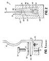
- FIG. 2is a sectional view of an assembly for attaching a fabric component to a metal component according to a first preferred embodiment of the present invention.
- the present inventionprovides a means for attaching a fabric component to a metal component which is both relatively compact and lightweight, yet which also provides the requisite secure attachment between the components.
- the present inventionadvantageously relates to a means for anchoring the fabric component by casting a low melting point yet high compressive strength material into a cavity in the metal component.
- the assembly 110 for attaching fabric to metalcomprises (a) a metal housing 120 comprising an interior entrance 121 , at least first and second opposed interior walls 122 , and an interior end 123 opposite the interior entrance 121 , the at least first and second opposed interior walls 122 and the interior end 123 defining an interior cavity; (b) a fabric 130 ; (c) a fabric anchor assembly 140 ; and (d) a castable material 150 disposed in the interior cavity so as to envelop the fabric 130 and the fabric anchor assembly 140 .
- fabric 130comprises a first fabric portion 131 and a second fabric portion 132
- fabric anchor assembly 140comprises an anchor 141 and a means for attaching fabric 130 to anchor 141 , such as, for example, stitching 142 .
- Anchor 141is preferably of a construction which does not contain voids (which can lead to compression of the anchor), and therefore is typically a monofilament, a cable, or a wire.
- the attachment assembly 110comprises a metal housing 120 comprising an undercut, e.g., a dovetail-shaped, cavity at the fabric/metal attachment interface (i.e., that portion of the assembly adjacent to interior entrance 121 ), fabric 130 comprising first fabric portion 131 and second fabric portion 132 , anchor 141 , stitching 142 , and castable material 150 .
- an undercute.g., a dovetail-shaped, cavity at the fabric/metal attachment interface (i.e., that portion of the assembly adjacent to interior entrance 121 )
- fabric 130comprising first fabric portion 131 and second fabric portion 132 , anchor 141 , stitching 142 , and castable material 150 .
- Castable material 150is a high compressive strength material.
- Polymeric materialsincluding both thermoplastic and thermosetting types, are suitable for use as the castable material.
- the materialshould typically be one which has a relatively low melting point, e.g., thermoplastic polymeric materials and low melting point metal alloys.
- the thermoplastic polymeric materialcould be a hot melt adhesive
- the low melting point metal alloycould be a low melting point solder alloy.
- thermoplastic polymeric materials and low melting point metal alloysare preferred insofar as they can be easily removed to facilitate disassembly of the components.
- assembly 110can be easily disassembled for repair or replacement of components by simply melting castable material 150 out of the interior cavity.
- the fabric and fabric anchor assemblycan be locked in place by filling the interior cavity with a thermoset material, such as, for example, an epoxy.
- the assemblyfurther comprises a coating of rigidized thermoplastic adhesive disposed on each of first and second opposed interior walls 122 of metal housing 120 .
- Walls 122are coated with a rigid thermoplastic adhesive compatible with the hot melt adhesive and/or low melting point solder alloy so as to provide for adhesion of castable material 150 to the walls 122 .
- This embodimentprovides for a level of structural and leakage integrity even beyond that afforded by the mechanical locking action of the castable material in the cavity.
- the assemblyfurther comprises a flexible sealant 160 disposed in a portion of the interior cavity located between castable material 150 and interior entrance 121 .
- This flexible sealantserves as a transition section to reduce the stress concentration of the fabric at the fabric/metal interface.
- the assemblyfurther comprises a bladder layer disposed so as to be contiguous with fabric 130 .
- the bladder layerthus contacts the hot melt adhesive and/or low melting point solder alloy so as to improve adhesion.
- the inventionfurther relates to a method of fabricating assembly 110 for attaching fabric to metal.
- the methodcomprises the steps of (a) anchoring fabric 130 with fabric anchor assembly 140 ; (b) inserting the anchored fabric in the interior cavity; (c) providing the interior cavity with the castable material 150 so as to envelop the anchored fabric; and (d) solidifying the castable material to a cast material so as to provide the assembly 110 .
- the method of fabricating assembly 110comprises the steps of (a) folding first fabric portion 131 over anchor 141 , and folding folded first fabric portion 131 back against second fabric portion 132 ; (b) attaching folded first fabric portion 131 to second fabric portion 132 with the means for attaching so as to provide an anchored fabric; (c) inserting the anchored fabric in the interior cavity; (d) providing the interior cavity with castable material 150 so as to envelop the anchored fabric; and (e) solidifying castable material 150 to a cast material so as to provide assembly 110 .
- an undercut interior cavitye.g., a dovetail-shaped cavity having a first end and a second end is provided in metal housing 120 by a method such as machining.
- the cross section of the cavitycan be made to follow the contour of the fabric/metal interface (e.g., circular, cylindrical, or any other desired shape).
- fabric anchor assembly 140(sometimes generically referred to as a “deadman”) is fabricated by folding first fabric portion 131 of fabric 130 over anchor 141 (which is, typically, the aforementioned monofilament, cable, or wire), and then folding first fabric portion 131 back against second fabric portion 132 .
- First fabric portion 131 and second fabric portion 132are then attached to one another by a suitable means for attaching, such as, for example, stitching 142 .
- interior entrance 121 of metal housing 120has a width that is slightly larger than the diameter of fabric anchor assembly 140 .
- castable material 150is provided within the cavity so as to envelop fabric 130 and fabric anchor assembly 140 .
- Castable material 150is then solidified to form a cast material, so as to mechanically lock fabric 130 and fabric anchor assembly 140 in place, and thus provide assembly 110 .
- the methodfurther comprises after step (a) and before step (b) a step of providing a coating of rigidizable thermoplastic adhesive disposed on each of the first and second opposed interior walls 122 .
- the methodfurther comprises after step (c) and before step (d) a step of providing a flexible sealant 160 disposed in a portion of the interior cavity located between castable material 150 and interior entrance 121 .
- the methodfurther comprises after step (b) and before step (c) a step of providing a bladder layer disposed so as to be contiguous with the fabric 130 .
- the present inventiontherefore, provides a means for anchoring a fabric component by casting a low melting point yet high compressive strength material into a cavity in a metal component.
- Advantages associated with the inventioninclude not only its compact size and light weight, but the requisite mechanical integrity of the resulting attachment.
- the assemblycan be easily disassembled for repair or replacement of components by simply melting the castable material out of the interior cavity.
Landscapes
- Chemical & Material Sciences (AREA)
- Engineering & Computer Science (AREA)
- Composite Materials (AREA)
- Mechanical Engineering (AREA)
- Connection Of Plates (AREA)
- Joining Of Building Structures In Genera (AREA)
- Furnace Housings, Linings, Walls, And Ceilings (AREA)
Abstract
Description
Claims (14)
Priority Applications (1)
| Application Number | Priority Date | Filing Date | Title |
|---|---|---|---|
| US10/650,806US6881689B2 (en) | 1999-06-10 | 2003-08-29 | Assembly for attaching fabric to metal and method of fabrication therefor |
Applications Claiming Priority (3)
| Application Number | Priority Date | Filing Date | Title |
|---|---|---|---|
| US13853699P | 1999-06-10 | 1999-06-10 | |
| US09/589,771US6612360B1 (en) | 1999-06-10 | 2000-06-09 | Assembly for attaching fabric to metal and method of fabrication therefor |
| US10/650,806US6881689B2 (en) | 1999-06-10 | 2003-08-29 | Assembly for attaching fabric to metal and method of fabrication therefor |
Related Parent Applications (2)
| Application Number | Title | Priority Date | Filing Date |
|---|---|---|---|
| US09/589,771DivisionUS6612360B1 (en) | 1999-06-10 | 2000-06-09 | Assembly for attaching fabric to metal and method of fabrication therefor |
| US09/589,771ContinuationUS6612360B1 (en) | 1999-06-10 | 2000-06-09 | Assembly for attaching fabric to metal and method of fabrication therefor |
Publications (2)
| Publication Number | Publication Date |
|---|---|
| US20040011494A1 US20040011494A1 (en) | 2004-01-22 |
| US6881689B2true US6881689B2 (en) | 2005-04-19 |
Family
ID=27767410
Family Applications (2)
| Application Number | Title | Priority Date | Filing Date |
|---|---|---|---|
| US09/589,771Expired - LifetimeUS6612360B1 (en) | 1999-06-10 | 2000-06-09 | Assembly for attaching fabric to metal and method of fabrication therefor |
| US10/650,806Expired - LifetimeUS6881689B2 (en) | 1999-06-10 | 2003-08-29 | Assembly for attaching fabric to metal and method of fabrication therefor |
Family Applications Before (1)
| Application Number | Title | Priority Date | Filing Date |
|---|---|---|---|
| US09/589,771Expired - LifetimeUS6612360B1 (en) | 1999-06-10 | 2000-06-09 | Assembly for attaching fabric to metal and method of fabrication therefor |
Country Status (1)
| Country | Link |
|---|---|
| US (2) | US6612360B1 (en) |
Cited By (3)
| Publication number | Priority date | Publication date | Assignee | Title |
|---|---|---|---|---|
| US20060061010A1 (en)* | 2004-09-13 | 2006-03-23 | Hans-Georg Huonker | Process for manufacturing hybrid components as well as components manufactured according to this process |
| US20070001844A1 (en)* | 2004-06-28 | 2007-01-04 | Krill Jerry A | Security material and fasteners therefor |
| US20090140857A1 (en)* | 2004-06-28 | 2009-06-04 | Krill Jerry A | Anti-Tampering Security Material |
Families Citing this family (4)
| Publication number | Priority date | Publication date | Assignee | Title |
|---|---|---|---|---|
| US6612360B1 (en)* | 1999-06-10 | 2003-09-02 | Ilc Dover, Inc. | Assembly for attaching fabric to metal and method of fabrication therefor |
| CN103122633B (en)* | 2013-02-19 | 2015-08-19 | 中冶集团武汉勘察研究院有限公司 | Electric-melting pressure-type recoverable anchor rod construction method |
| CN110496953B (en)* | 2019-08-30 | 2021-06-29 | 海洋石油工程股份有限公司 | Steel wire rope section casting steel wire pre-arrangement equipment and use method thereof |
| DE102020102384B4 (en) | 2020-01-31 | 2025-09-04 | HELLA GmbH & Co. KGaA | Joining connection, motor vehicle lighting device and joining process |
Citations (21)
| Publication number | Priority date | Publication date | Assignee | Title |
|---|---|---|---|---|
| US2824595A (en) | 1954-01-18 | 1958-02-25 | Lehre Frithjof | Method of fastening buttons to textile articles |
| US3650647A (en)* | 1969-05-21 | 1972-03-21 | Jacobs Machine Corp | Apparatus for securing buttons to fabric |
| US3998922A (en) | 1976-01-28 | 1976-12-21 | Weiss Theodore H | Method of making a candle in a container |
| US4030953A (en) | 1976-02-11 | 1977-06-21 | Scala Radio Corporation | Method of molding fiberglass reflecting antenna |
| US4332548A (en) | 1979-09-24 | 1982-06-01 | Avon Products, Inc. | Candle safety disc and candle |
| US4357193A (en) | 1979-05-21 | 1982-11-02 | Rockwell International Corporation | Method of fabricating a composite structure |
| US4508158A (en) | 1983-02-22 | 1985-04-02 | International Harvester Company | Graphite-metal matrix bearings and methods of manufacturing |
| US4573517A (en) | 1982-02-08 | 1986-03-04 | The Secretary Of State For Defence In Her Britannic Majesty's Government Of The United Kingdom Of Great Britain And Northern Ireland | Fiber-reinforced metals |
| US4673150A (en) | 1984-10-22 | 1987-06-16 | Mechanical Plastics Corp. | Plastic fasteners |
| US4839215A (en) | 1986-06-09 | 1989-06-13 | Ceramed Corporation | Biocompatible particles and cloth-like article made therefrom |
| US5370921A (en) | 1991-07-11 | 1994-12-06 | The Dexter Corporation | Lightning strike composite and process |
| US5511604A (en) | 1993-06-15 | 1996-04-30 | General Electric Company | Method for making a titanium metal matrix composite |
| US5570502A (en) | 1991-04-08 | 1996-11-05 | Aluminum Company Of America | Fabricating metal matrix composites containing electrical insulators |
| US5632320A (en) | 1995-08-16 | 1997-05-27 | Northrop Grumman Corporation | Methods and apparatus for making ceramic matrix composite lined automotive parts and fiber reinforced ceramic matrix composite automotive parts |
| US5662157A (en) | 1991-07-29 | 1997-09-02 | Pcc Composites, Inc. | Package and a method of forming a metal matrix component with internal and external structures |
| US5842850A (en)* | 1997-04-09 | 1998-12-01 | Lumi-Lite Candle Company, Inc. | Anti-flash wick sustainer and pedestal |
| US5932496A (en) | 1995-05-26 | 1999-08-03 | The Secretary Of State For Defence In Her Britannic Majesty's Government Of The United Kingdom Of Great Britain And Northern Ireland | Composite materials |
| US5939005A (en) | 1998-10-29 | 1999-08-17 | S.C. Johnson & Son, Inc. | Candle forming method |
| US5967769A (en)* | 1997-08-26 | 1999-10-19 | Campfire, Inc. | Ready to use campfire |
| US6221795B1 (en) | 1996-10-18 | 2001-04-24 | Mtu Motoren-Und Turbinen-Union Muenchen Gmbh | Composite material and process for manufacturing same |
| US6612360B1 (en)* | 1999-06-10 | 2003-09-02 | Ilc Dover, Inc. | Assembly for attaching fabric to metal and method of fabrication therefor |
Family Cites Families (8)
| Publication number | Priority date | Publication date | Assignee | Title |
|---|---|---|---|---|
| US2255184A (en)* | 1938-01-22 | 1941-09-09 | Osenberg Werner | Method of bonding metal to insulation |
| US3713936A (en)* | 1971-02-01 | 1973-01-30 | Celanese Corp | Fabric molding |
| US4186235A (en)* | 1975-04-24 | 1980-01-29 | Imperial Chemical Industries Limited | Thermoplastics articles having a surface fused to cloth |
| US4735753A (en)* | 1986-07-28 | 1988-04-05 | Ackermann Walter T | Method of making a fastener |
| US5275548A (en)* | 1989-11-07 | 1994-01-04 | G.T. S.A.S. Di Giuseppe Tibiletti & C | Mold for making seals, in particular for garment labels |
| US6004662A (en)* | 1992-07-14 | 1999-12-21 | Buckley; Theresa M. | Flexible composite material with phase change thermal storage |
| US5476627A (en)* | 1994-06-24 | 1995-12-19 | Bell Helicopter Textron Inc. | Composite molding process utilizing tackified fabric material |
| US6096251A (en)* | 1995-12-22 | 2000-08-01 | Plastic Omnium Auto Interieur | Method and apparatus for the manufacture of a multilayered object |
- 2000
- 2000-06-09USUS09/589,771patent/US6612360B1/ennot_activeExpired - Lifetime
- 2003
- 2003-08-29USUS10/650,806patent/US6881689B2/ennot_activeExpired - Lifetime
Patent Citations (21)
| Publication number | Priority date | Publication date | Assignee | Title |
|---|---|---|---|---|
| US2824595A (en) | 1954-01-18 | 1958-02-25 | Lehre Frithjof | Method of fastening buttons to textile articles |
| US3650647A (en)* | 1969-05-21 | 1972-03-21 | Jacobs Machine Corp | Apparatus for securing buttons to fabric |
| US3998922A (en) | 1976-01-28 | 1976-12-21 | Weiss Theodore H | Method of making a candle in a container |
| US4030953A (en) | 1976-02-11 | 1977-06-21 | Scala Radio Corporation | Method of molding fiberglass reflecting antenna |
| US4357193A (en) | 1979-05-21 | 1982-11-02 | Rockwell International Corporation | Method of fabricating a composite structure |
| US4332548A (en) | 1979-09-24 | 1982-06-01 | Avon Products, Inc. | Candle safety disc and candle |
| US4573517A (en) | 1982-02-08 | 1986-03-04 | The Secretary Of State For Defence In Her Britannic Majesty's Government Of The United Kingdom Of Great Britain And Northern Ireland | Fiber-reinforced metals |
| US4508158A (en) | 1983-02-22 | 1985-04-02 | International Harvester Company | Graphite-metal matrix bearings and methods of manufacturing |
| US4673150A (en) | 1984-10-22 | 1987-06-16 | Mechanical Plastics Corp. | Plastic fasteners |
| US4839215A (en) | 1986-06-09 | 1989-06-13 | Ceramed Corporation | Biocompatible particles and cloth-like article made therefrom |
| US5570502A (en) | 1991-04-08 | 1996-11-05 | Aluminum Company Of America | Fabricating metal matrix composites containing electrical insulators |
| US5370921A (en) | 1991-07-11 | 1994-12-06 | The Dexter Corporation | Lightning strike composite and process |
| US5662157A (en) | 1991-07-29 | 1997-09-02 | Pcc Composites, Inc. | Package and a method of forming a metal matrix component with internal and external structures |
| US5511604A (en) | 1993-06-15 | 1996-04-30 | General Electric Company | Method for making a titanium metal matrix composite |
| US5932496A (en) | 1995-05-26 | 1999-08-03 | The Secretary Of State For Defence In Her Britannic Majesty's Government Of The United Kingdom Of Great Britain And Northern Ireland | Composite materials |
| US5632320A (en) | 1995-08-16 | 1997-05-27 | Northrop Grumman Corporation | Methods and apparatus for making ceramic matrix composite lined automotive parts and fiber reinforced ceramic matrix composite automotive parts |
| US6221795B1 (en) | 1996-10-18 | 2001-04-24 | Mtu Motoren-Und Turbinen-Union Muenchen Gmbh | Composite material and process for manufacturing same |
| US5842850A (en)* | 1997-04-09 | 1998-12-01 | Lumi-Lite Candle Company, Inc. | Anti-flash wick sustainer and pedestal |
| US5967769A (en)* | 1997-08-26 | 1999-10-19 | Campfire, Inc. | Ready to use campfire |
| US5939005A (en) | 1998-10-29 | 1999-08-17 | S.C. Johnson & Son, Inc. | Candle forming method |
| US6612360B1 (en)* | 1999-06-10 | 2003-09-02 | Ilc Dover, Inc. | Assembly for attaching fabric to metal and method of fabrication therefor |
Cited By (5)
| Publication number | Priority date | Publication date | Assignee | Title |
|---|---|---|---|---|
| US20070001844A1 (en)* | 2004-06-28 | 2007-01-04 | Krill Jerry A | Security material and fasteners therefor |
| US7352284B2 (en) | 2004-06-28 | 2008-04-01 | The Johns Hopkins University | Security material and fasteners therefor |
| US20090140857A1 (en)* | 2004-06-28 | 2009-06-04 | Krill Jerry A | Anti-Tampering Security Material |
| US7646299B2 (en) | 2004-06-28 | 2010-01-12 | The John Hopkins University | Anti-tampering security material |
| US20060061010A1 (en)* | 2004-09-13 | 2006-03-23 | Hans-Georg Huonker | Process for manufacturing hybrid components as well as components manufactured according to this process |
Also Published As
| Publication number | Publication date |
|---|---|
| US20040011494A1 (en) | 2004-01-22 |
| US6612360B1 (en) | 2003-09-02 |
Similar Documents
| Publication | Publication Date | Title |
|---|---|---|
| US6881689B2 (en) | Assembly for attaching fabric to metal and method of fabrication therefor | |
| US8079773B2 (en) | Methods and apparatus for assembling composite structures | |
| US6968755B2 (en) | Lightweight bearing and wave gear drive | |
| US7047596B2 (en) | Structural bushing application for highly loaded composites lugs | |
| US6070914A (en) | Pipe coupling | |
| CA2266831C (en) | Seal structure for gas turbine | |
| AU758765B2 (en) | Casing design for rotating machinery and method for manufacture thereof | |
| GB2449907A (en) | Composite flange, manufacture of the flange and duct or casing with the flange | |
| US6670021B2 (en) | Monolithic ceramic attachment bushing incorporated into a ceramic matrix composite component and related method | |
| CN102575705A (en) | Ball joint | |
| GB2262576A (en) | Flanged bearings. | |
| AU3854099A (en) | Coupling sleeve for high-pressure pipe | |
| WO1999019654A1 (en) | A flexible pipe with an associated end-fitting | |
| EP1327801A2 (en) | A composite tubular woven seal for an inner compressor discharge case | |
| EP0969217A2 (en) | Composite spherical bearing and method of producing same | |
| DE102009005956A1 (en) | magnetic ring | |
| KR102852162B1 (en) | Marine frame structure including structural members and structural joints connecting the structural members | |
| CN103043203A (en) | Device for manoeuvring a watercraft | |
| US5407508A (en) | Method for producing a replaceable outer race for ball and socket bearing | |
| US5724715A (en) | Composite flange for drive shafts | |
| US12152629B2 (en) | Attachment structure having a connection member with multiple attachment features | |
| US5288114A (en) | Attachment methodology for composite cylinder assembly | |
| JP2005512003A (en) | Cover for housing | |
| JPH1088984A (en) | segment | |
| JP2598927Y2 (en) | Shaft sealing device |
Legal Events
| Date | Code | Title | Description |
|---|---|---|---|
| STCF | Information on status: patent grant | Free format text:PATENTED CASE | |
| AS | Assignment | Owner name:UBS AG, STAMFORD BRANCH, AS COLLATERAL AGENT, CONN Free format text:FIRST LIEN PATENT SECURITY AGREEMENT;ASSIGNORS:DATA DEVICE CORPORATION;ILC DOVER IP, INC.;REEL/FRAME:016489/0902 Effective date:20050824 | |
| AS | Assignment | Owner name:UBS AG, STAMFORD BRANCH, AS COLLATERAL AGENT, CONN Free format text:SECURITY AGREEMENT;ASSIGNORS:DATA DEVICE CORPORATION;ILC DOVER IP, INC.;REEL/FRAME:016500/0573 Effective date:20050824 | |
| AS | Assignment | Owner name:DATA DEVICE CORPORATION, NEW YORK Free format text:TERMINATION AND RELEASE OF SECURITY INTEREST PATENTS;ASSIGNORS:UBS AG, STAMFORD BRANCH, AS COLLATERAL AGENT;ILC DOVER LP (FORMERLY KNOWN AS ILC DOVER, INCORPORATED);REEL/FRAME:017897/0613 Effective date:20060628 | |
| AS | Assignment | Owner name:DATA DEVICE CORPORATION, NEW YORK Free format text:TERMINATION AND RELEASE OF SECURITY INTEREST IN PATENTS;ASSIGNOR:UBS AG, STAMFORD BRANCH, AS COLLATERAL AGENT;REEL/FRAME:017906/0641 Effective date:20060628 Owner name:ILC DOVER LP (FORMERLY KNOWN AS ILC DOVER, INCORPO Free format text:TERMINATION AND RELEASE OF SECURITY INTEREST IN PATENTS;ASSIGNOR:UBS AG, STAMFORD BRANCH, AS COLLATERAL AGENT;REEL/FRAME:017906/0641 Effective date:20060628 | |
| AS | Assignment | Owner name:UBS AG, STAMFORD BRANCH, AS COLLATERAL AGENT, CONN Free format text:FIRST LIEN PATENT SECURITY AGREEMENT;ASSIGNORS:DATA DEVICE CORPORATION;ILC DOVER IP, INC.;REEL/FRAME:017914/0917 Effective date:20060628 | |
| AS | Assignment | Owner name:WELLS FARGO BANK, MINNESOTA Free format text:SECOND LIEN PATENT SECURITY AGREEMENT;ASSIGNOR:DATA DEVICE CORPORATION;REEL/FRAME:018412/0209 Effective date:20060628 | |
| FPAY | Fee payment | Year of fee payment:4 | |
| AS | Assignment | Owner name:ILC DOVER LP, DELAWARE Free format text:RELEASE OF SECURITY INTEREST AT 017914/0917, 022777/0101, 023084/0234, & 024373/0200;ASSIGNOR:UBS AG, STAMFORD BRANCH;REEL/FRAME:025562/0193 Effective date:20101223 Owner name:GENERAL ELECTRIC CAPITAL CORPORATION, AS AGENT, IL Free format text:SECURITY AGREEMENT;ASSIGNORS:ILC DOVER LP;ILC DOVER IP, INC.;REEL/FRAME:025562/0201 Effective date:20101223 Owner name:ILC DOVER LP, DELAWARE Free format text:RELEASE OF SECURITY INTEREST AT 018412/0209 & 024396/0248;ASSIGNOR:WELLS FARGO BANK, NATIONAL ASSOCIATION;REEL/FRAME:025562/0185 Effective date:20101223 Owner name:DATA DEVICE CORPORATION, NEW YORK Free format text:RELEASE OF SECURITY INTEREST AT 017914/0917, 022777/0101, 023084/0234, & 024373/0200;ASSIGNOR:UBS AG, STAMFORD BRANCH;REEL/FRAME:025562/0193 Effective date:20101223 Owner name:ILC DOVER IP, INC., DELAWARE Free format text:RELEASE OF SECURITY INTEREST AT 017914/0917, 022777/0101, 023084/0234, & 024373/0200;ASSIGNOR:UBS AG, STAMFORD BRANCH;REEL/FRAME:025562/0193 Effective date:20101223 Owner name:DATA DEVICE CORPORATION, NEW YORK Free format text:RELEASE OF SECURITY INTEREST AT 018412/0209 & 024396/0248;ASSIGNOR:WELLS FARGO BANK, NATIONAL ASSOCIATION;REEL/FRAME:025562/0185 Effective date:20101223 Owner name:ILC DOVER IP, INC., DELAWARE Free format text:RELEASE OF SECURITY INTEREST AT 018412/0209 & 024396/0248;ASSIGNOR:WELLS FARGO BANK, NATIONAL ASSOCIATION;REEL/FRAME:025562/0185 Effective date:20101223 | |
| AS | Assignment | Owner name:ILC DOVER LP, DELAWARE Free format text:RELEASE BY SECURED PARTY;ASSIGNOR:GENERAL ELECTRIC CAPITAL CORPORATION;REEL/FRAME:028530/0095 Effective date:20120711 Owner name:ILC DOVER IP, INC., DELAWARE Free format text:RELEASE BY SECURED PARTY;ASSIGNOR:GENERAL ELECTRIC CAPITAL CORPORATION;REEL/FRAME:028530/0095 Effective date:20120711 Owner name:THE GOVERNOR AND COMPANY OF THE BANK OF IRELAND, C Free format text:SECURITY AGREEMENT;ASSIGNORS:ILC DOVER LP;IC DOVER IP, INC.;REEL/FRAME:028545/0420 Effective date:20120711 | |
| AS | Assignment | Owner name:OCM FIE, LLC, AS COLLATERAL AGENT, NEW YORK Free format text:SECURITY AGREEMENT;ASSIGNORS:ILC DOVER LP;ILC DOVER IP, INC.;REEL/FRAME:028686/0076 Effective date:20120711 | |
| FPAY | Fee payment | Year of fee payment:8 | |
| SULP | Surcharge for late payment | Year of fee payment:7 | |
| AS | Assignment | Owner name:GCI CAPITAL MARKETS LLC, AS COLLATERAL AGENT, ILLI Free format text:SECURITY INTEREST;ASSIGNORS:ILC DOVER IP, INC.;GRAYLING INDUSTRIES, INC.;ILC DOVER LP;REEL/FRAME:032506/0009 Effective date:20140320 | |
| AS | Assignment | Owner name:ILC DOVER LP, DELAWARE Free format text:RELEASE BY SECURED PARTY;ASSIGNOR:THE GOVERNOR AND COMPANY OF THE BANK OF IRELAND, AS COLLATERAL AGENT;REEL/FRAME:032534/0830 Effective date:20140320 Owner name:ILC DOVER IP, INC., DELAWARE Free format text:RELEASE BY SECURED PARTY;ASSIGNOR:THE GOVERNOR AND COMPANY OF THE BANK OF IRELAND, AS COLLATERAL AGENT;REEL/FRAME:032534/0830 Effective date:20140320 Owner name:ILC DOVER LP, DELAWARE Free format text:RELEASE BY SECURED PARTY;ASSIGNOR:OCM FIE, LLC, AS AGENT;REEL/FRAME:032528/0827 Effective date:20140320 Owner name:ILC DOVER IP, INC., DELAWARE Free format text:RELEASE BY SECURED PARTY;ASSIGNOR:OCM FIE, LLC, AS AGENT;REEL/FRAME:032528/0827 Effective date:20140320 | |
| AS | Assignment | Owner name:UBS AG, STAMFORD BRANCH, AS COLLATERAL AGENT, CONN Free format text:CORRECTIVE ASSIGNMENT TO REMOVE APPLICATION NO. 10/020,936 PREVIOUSLY RECORDED AT REEL: 016500 FRAME: 0573. ASSIGNOR(S) HEREBY CONFIRMS THE SECURITY AGREEMENT;ASSIGNORS:DATA DEVICE CORPORATION;ILC DOVER IP, INC.;REEL/FRAME:038607/0402 Effective date:20050824 Owner name:DATA DEVICE CORPORATION, NEW YORK Free format text:CORRECTIVE ASSIGNMENT TO REMOVE PATENT NO. 6,834,646 PREVIOUSLY RECORDED AT REEL: 017906 FRAME: 0641. ASSIGNOR(S) HEREBY CONFIRMS THE TERMINATION AND RELEASE OF SECURITY INTEREST;ASSIGNOR:UBS AG, STAMFORD BRANCH, AS COLLATERAL AGENT;REEL/FRAME:038607/0550 Effective date:20060628 Owner name:ILC DOVER LP (FORMERLY KNOWN AS ILC DOVER, INCORPO Free format text:CORRECTIVE ASSIGNMENT TO REMOVE PATENT NO. 6,834,646 PREVIOUSLY RECORDED AT REEL: 017906 FRAME: 0641. ASSIGNOR(S) HEREBY CONFIRMS THE TERMINATION AND RELEASE OF SECURITY INTEREST;ASSIGNOR:UBS AG, STAMFORD BRANCH, AS COLLATERAL AGENT;REEL/FRAME:038607/0550 Effective date:20060628 Owner name:UBS AG, STAMFORD BRANCH, AS COLLATERAL AGENT, CONN Free format text:CORRECTIVE ASSIGNMENT TO CORRECT THE U.S. APPLICATION NO. 10/020,936 SHOULD BE REMOVED FROM THE LIST OF PROPERTIES. PREVIOUSLY RECORDED ON REEL 016489 FRAME 0902. ASSIGNOR(S) HEREBY CONFIRMS THE FIRST LIEN PATENT SECURITY AGREEMENT;ASSIGNORS:DATA DEVICE CORPORATION;ILC DOVER IP, INC.;REEL/FRAME:038585/0856 Effective date:20050824 Owner name:DATA DEVICE CORPORATION, NEW YORK Free format text:CORRECTIVE ASSIGNMENT TO CORRECT THE REMOVE PATENT NO. 6,834,646 PREVIOUSLY RECORDED AT REEL: 017897 FRAME: 0613. ASSIGNOR(S) HEREBY CONFIRMS THE TERMINATION AND RELEASE OF SECURITY INTEREST PATENTS;ASSIGNORS:UBS AG, STAMFORD BRANCH, AS COLLATERAL AGENT;ILC DOVER LP (FORMERLY KNOWN AS ILC DOVER, INCORPORATED);REEL/FRAME:038842/0990 Effective date:20060628 | |
| FPAY | Fee payment | Year of fee payment:12 | |
| AS | Assignment | Owner name:ANTARES CAPITAL LP, AS COLLATERAL AGENT, ILLINOIS Free format text:SECURITY INTEREST;ASSIGNORS:ILC DOVER LP;ILC DOVER IP, INC.;GRAYLING INDUSTRIES, INC.;REEL/FRAME:044499/0944 Effective date:20171228 Owner name:ILC DOVER IP, INC., DELAWARE Free format text:RELEASE BY SECURED PARTY;ASSIGNOR:GOLUB CAPITAL MARKETS, LLC, AS COLLATERAL AGENT (F/K/A GCI CAPITAL MARKETS LLC);REEL/FRAME:044501/0959 Effective date:20171228 Owner name:GRAYLING INDUSTRIES, INC., DELAWARE Free format text:RELEASE BY SECURED PARTY;ASSIGNOR:GOLUB CAPITAL MARKETS, LLC, AS COLLATERAL AGENT (F/K/A GCI CAPITAL MARKETS LLC);REEL/FRAME:044501/0959 Effective date:20171228 Owner name:ADAMS STREET CREDIT ADVISORS LP, AS COLLATERAL AGE Free format text:SECURITY INTEREST;ASSIGNORS:ILC DOVER LP;ILC DOVER IP, INC.;GRAYLING INDUSTRIES, INC.;REEL/FRAME:044502/0051 Effective date:20171228 Owner name:ILC DOVER LP, DELAWARE Free format text:RELEASE BY SECURED PARTY;ASSIGNOR:GOLUB CAPITAL MARKETS, LLC, AS COLLATERAL AGENT (F/K/A GCI CAPITAL MARKETS LLC);REEL/FRAME:044501/0959 Effective date:20171228 | |
| AS | Assignment | Owner name:ILC DOVER IP, INC., DELAWARE Free format text:CORRECTIVE ASSIGNMENT TO CORRECT THE PATENT NUMBER 6305846 PREVIOUSLY RECORDED ON REEL 044501 FRAME 0959. ASSIGNOR(S) HEREBY CONFIRMS THE RELEASE BY SECURED PARTY;ASSIGNOR:GOLUB CAPITAL MARKETS, LLC, AS COLLATERAL AGENT (F/K/A GCI CAPITAL MARKETS LLC);REEL/FRAME:045054/0365 Effective date:20171228 Owner name:ILC DOVER LP, DELAWARE Free format text:CORRECTIVE ASSIGNMENT TO CORRECT THE PATENT NUMBER 6305846 PREVIOUSLY RECORDED ON REEL 044501 FRAME 0959. ASSIGNOR(S) HEREBY CONFIRMS THE RELEASE BY SECURED PARTY;ASSIGNOR:GOLUB CAPITAL MARKETS, LLC, AS COLLATERAL AGENT (F/K/A GCI CAPITAL MARKETS LLC);REEL/FRAME:045054/0365 Effective date:20171228 Owner name:GRAYLING INDUSTRIES, INC., DELAWARE Free format text:CORRECTIVE ASSIGNMENT TO CORRECT THE PATENT NUMBER 6305846 PREVIOUSLY RECORDED ON REEL 044501 FRAME 0959. ASSIGNOR(S) HEREBY CONFIRMS THE RELEASE BY SECURED PARTY;ASSIGNOR:GOLUB CAPITAL MARKETS, LLC, AS COLLATERAL AGENT (F/K/A GCI CAPITAL MARKETS LLC);REEL/FRAME:045054/0365 Effective date:20171228 | |
| AS | Assignment | Owner name:ANTARES CAPITAL LP, AS ADMINISTRATIVE AGENT, ILLINOIS Free format text:SECURITY INTEREST;ASSIGNORS:ILC DOVER IP, INC.;ILC DOVER LP;GRAYLING INDUSTRIES, INC.;REEL/FRAME:051686/0812 Effective date:20200131 | |
| AS | Assignment | Owner name:ILC DOVER IP, INC., DELAWARE Free format text:INTELLECTUAL PROPERTY RELEASE AND REASSIGNMENT;ASSIGNOR:ADAMS STREET CREDIT ADVISORS LP;REEL/FRAME:051839/0878 Effective date:20200131 Owner name:GRAYLING INDUSTRIES, INC., DELAWARE Free format text:INTELLECTUAL PROPERTY RELEASE AND REASSIGNMENT;ASSIGNOR:ANTARES CAPITAL LP;REEL/FRAME:051839/0794 Effective date:20200131 Owner name:ILC DOVER IP, INC., DELAWARE Free format text:INTELLECTUAL PROPERTY RELEASE AND REASSIGNMENT;ASSIGNOR:ANTARES CAPITAL LP;REEL/FRAME:051839/0794 Effective date:20200131 Owner name:ILC DOVER LP, DELAWARE Free format text:INTELLECTUAL PROPERTY RELEASE AND REASSIGNMENT;ASSIGNOR:ANTARES CAPITAL LP;REEL/FRAME:051839/0794 Effective date:20200131 Owner name:ILC DOVER LP, DELAWARE Free format text:INTELLECTUAL PROPERTY RELEASE AND REASSIGNMENT;ASSIGNOR:ADAMS STREET CREDIT ADVISORS LP;REEL/FRAME:051839/0878 Effective date:20200131 Owner name:GRAYLING INDUSTRIES, INC., DELAWARE Free format text:INTELLECTUAL PROPERTY RELEASE AND REASSIGNMENT;ASSIGNOR:ADAMS STREET CREDIT ADVISORS LP;REEL/FRAME:051839/0878 Effective date:20200131 | |
| AS | Assignment | Owner name:ILC DOVER LP, DELAWARE Free format text:CONFIRMATION OF TERMINATION AND RELEASE OF SECURITY INTEREST IN PATENT RIGHTS TO GENERAL ELECTRIC CAPITAL CORPORATION RECORDED AT REEL 25562 FRAME 0201;ASSIGNORS:ILC DOVER IP, INC.;ILC DOVER LP;REEL/FRAME:067593/0030 Effective date:20240530 Owner name:ILC DOVER IP, INC., DELAWARE Free format text:CONFIRMATION OF TERMINATION AND RELEASE OF SECURITY INTEREST IN PATENT RIGHTS TO GENERAL ELECTRIC CAPITAL CORPORATION RECORDED AT REEL 25562 FRAME 0201;ASSIGNORS:ILC DOVER IP, INC.;ILC DOVER LP;REEL/FRAME:067593/0030 Effective date:20240530 | |
| AS | Assignment | Owner name:ILC ASTROSPACE, LLC, DELAWARE Free format text:RELEASE BY SECURED PARTY;ASSIGNOR:ANTARES CAPITAL LP, AS ADMINISTRATIVE AGENT AND COLLATERAL AGENT;REEL/FRAME:067603/0073 Effective date:20240603 Owner name:ILC DOVER LP (AS SUCCESSOR-BY-MERGER TO GRAYLING INDUSTRIES, INC.), DELAWARE Free format text:RELEASE BY SECURED PARTY;ASSIGNOR:ANTARES CAPITAL LP, AS ADMINISTRATIVE AGENT AND COLLATERAL AGENT;REEL/FRAME:067603/0073 Effective date:20240603 Owner name:ILC DOVER IP, INC., DELAWARE Free format text:RELEASE BY SECURED PARTY;ASSIGNOR:ANTARES CAPITAL LP, AS ADMINISTRATIVE AGENT AND COLLATERAL AGENT;REEL/FRAME:067603/0073 Effective date:20240603 |