US6881463B2 - Irregular, rotational tessellation surface covering units and surface covering - Google Patents
Irregular, rotational tessellation surface covering units and surface coveringDownload PDFInfo
- Publication number
- US6881463B2 US6881463B2US10/395,537US39553703AUS6881463B2US 6881463 B2US6881463 B2US 6881463B2US 39553703 AUS39553703 AUS 39553703AUS 6881463 B2US6881463 B2US 6881463B2
- Authority
- US
- United States
- Prior art keywords
- units
- vertex
- surface covering
- unit
- degrees
- Prior art date
- Legal status (The legal status is an assumption and is not a legal conclusion. Google has not performed a legal analysis and makes no representation as to the accuracy of the status listed.)
- Expired - Lifetime, expires
Links
Images


Classifications
- B—PERFORMING OPERATIONS; TRANSPORTING
- B44—DECORATIVE ARTS
- B44D—PAINTING OR ARTISTIC DRAWING, NOT OTHERWISE PROVIDED FOR; PRESERVING PAINTINGS; SURFACE TREATMENT TO OBTAIN SPECIAL ARTISTIC SURFACE EFFECTS OR FINISHES
- B44D3/00—Accessories or implements for use in connection with painting or artistic drawing, not otherwise provided for; Methods or devices for colour determination, selection, or synthesis, e.g. use of colour tables
- B44D3/12—Paint cans; Brush holders; Containers for storing residual paint
- B44D3/122—Paint cans; Brush holders; Containers for storing residual paint having separate compartments for the different paint compounds
- B—PERFORMING OPERATIONS; TRANSPORTING
- B44—DECORATIVE ARTS
- B44C—PRODUCING DECORATIVE EFFECTS; MOSAICS; TARSIA WORK; PAPERHANGING
- B44C3/00—Processes, not specifically provided for elsewhere, for producing ornamental structures
- B44C3/12—Uniting ornamental elements to structures, e.g. mosaic plates
- B44C3/123—Mosaic constructs
- E—FIXED CONSTRUCTIONS
- E01—CONSTRUCTION OF ROADS, RAILWAYS, OR BRIDGES
- E01C—CONSTRUCTION OF, OR SURFACES FOR, ROADS, SPORTS GROUNDS, OR THE LIKE; MACHINES OR AUXILIARY TOOLS FOR CONSTRUCTION OR REPAIR
- E01C5/00—Pavings made of prefabricated single units
- E—FIXED CONSTRUCTIONS
- E04—BUILDING
- E04C—STRUCTURAL ELEMENTS; BUILDING MATERIALS
- E04C1/00—Building elements of block or other shape for the construction of parts of buildings
- E04C1/39—Building elements of block or other shape for the construction of parts of buildings characterised by special adaptations, e.g. serving for locating conduits, for forming soffits, cornices, or shelves, for fixing wall-plates or door-frames, for claustra
- E04C1/395—Building elements of block or other shape for the construction of parts of buildings characterised by special adaptations, e.g. serving for locating conduits, for forming soffits, cornices, or shelves, for fixing wall-plates or door-frames, for claustra for claustra, fences, planting walls, e.g. sound-absorbing
- E—FIXED CONSTRUCTIONS
- E04—BUILDING
- E04F—FINISHING WORK ON BUILDINGS, e.g. STAIRS, FLOORS
- E04F15/00—Flooring
- E04F15/02—Flooring or floor layers composed of a number of similar elements
- E—FIXED CONSTRUCTIONS
- E01—CONSTRUCTION OF ROADS, RAILWAYS, OR BRIDGES
- E01C—CONSTRUCTION OF, OR SURFACES FOR, ROADS, SPORTS GROUNDS, OR THE LIKE; MACHINES OR AUXILIARY TOOLS FOR CONSTRUCTION OR REPAIR
- E01C2201/00—Paving elements
- E01C2201/02—Paving elements having fixed spacing features
- E—FIXED CONSTRUCTIONS
- E01—CONSTRUCTION OF ROADS, RAILWAYS, OR BRIDGES
- E01C—CONSTRUCTION OF, OR SURFACES FOR, ROADS, SPORTS GROUNDS, OR THE LIKE; MACHINES OR AUXILIARY TOOLS FOR CONSTRUCTION OR REPAIR
- E01C2201/00—Paving elements
- E01C2201/06—Sets of paving elements
- E—FIXED CONSTRUCTIONS
- E01—CONSTRUCTION OF ROADS, RAILWAYS, OR BRIDGES
- E01C—CONSTRUCTION OF, OR SURFACES FOR, ROADS, SPORTS GROUNDS, OR THE LIKE; MACHINES OR AUXILIARY TOOLS FOR CONSTRUCTION OR REPAIR
- E01C2201/00—Paving elements
- E01C2201/12—Paving elements vertically interlocking
- E—FIXED CONSTRUCTIONS
- E04—BUILDING
- E04B—GENERAL BUILDING CONSTRUCTIONS; WALLS, e.g. PARTITIONS; ROOFS; FLOORS; CEILINGS; INSULATION OR OTHER PROTECTION OF BUILDINGS
- E04B2/00—Walls, e.g. partitions, for buildings; Wall construction with regard to insulation; Connections specially adapted to walls
- E04B2/02—Walls, e.g. partitions, for buildings; Wall construction with regard to insulation; Connections specially adapted to walls built-up from layers of building elements
- E04B2002/0202—Details of connections
- E04B2002/0204—Non-undercut connections, e.g. tongue and groove connections
- E04B2002/0208—Non-undercut connections, e.g. tongue and groove connections of trapezoidal shape
- E—FIXED CONSTRUCTIONS
- E04—BUILDING
- E04B—GENERAL BUILDING CONSTRUCTIONS; WALLS, e.g. PARTITIONS; ROOFS; FLOORS; CEILINGS; INSULATION OR OTHER PROTECTION OF BUILDINGS
- E04B2/00—Walls, e.g. partitions, for buildings; Wall construction with regard to insulation; Connections specially adapted to walls
- E04B2/02—Walls, e.g. partitions, for buildings; Wall construction with regard to insulation; Connections specially adapted to walls built-up from layers of building elements
- E04B2002/0202—Details of connections
- E04B2002/0204—Non-undercut connections, e.g. tongue and groove connections
- E04B2002/0215—Non-undercut connections, e.g. tongue and groove connections with separate protrusions
- E—FIXED CONSTRUCTIONS
- E04—BUILDING
- E04F—FINISHING WORK ON BUILDINGS, e.g. STAIRS, FLOORS
- E04F2201/00—Joining sheets or plates or panels
- E04F2201/09—Puzzle-type connections for interlocking male and female panel edge-parts
- E04F2201/095—Puzzle-type connections for interlocking male and female panel edge-parts with both connection parts, i.e. male and female connection parts alternating on one edge
- Y—GENERAL TAGGING OF NEW TECHNOLOGICAL DEVELOPMENTS; GENERAL TAGGING OF CROSS-SECTIONAL TECHNOLOGIES SPANNING OVER SEVERAL SECTIONS OF THE IPC; TECHNICAL SUBJECTS COVERED BY FORMER USPC CROSS-REFERENCE ART COLLECTIONS [XRACs] AND DIGESTS
- Y10—TECHNICAL SUBJECTS COVERED BY FORMER USPC
- Y10T—TECHNICAL SUBJECTS COVERED BY FORMER US CLASSIFICATION
- Y10T428/00—Stock material or miscellaneous articles
- Y10T428/16—Two dimensionally sectional layer
- Y10T428/163—Next to unitary web or sheet of equal or greater extent
- Y10T428/164—Continuous two dimensionally sectional layer
Definitions
- This disclosurerelates to repeating elements forming a surface covering, and more specifically to stones, bricks, pavers and tiles for forming surface coverings.
- Natural stone surface coveringsare constructed by fitting together irregularly sized and shaped flat stones, such as flagstone and slate. The work requires a skilled stonemason to select, cut and fit the stones. It is labor intensive, and accordingly expensive. Custom built natural stone surfaces, however, are very attractive and desirable.
- Another conventional surface coveringis constructed of manufactured pavers, bricks or tiles.
- Manufactured paversare typically provided in geometric shapes, such as squares, rectangles and hexagons, or combinations thereof.
- Surfaces covered with manufactured paverstypically are laid in repeating patterns, such as, “herring-bone.”
- random patterns of manufactured bricksdo not have the degree of natural irregularity that is desirable in custom stone walkways, driveways, patios and the like.
- irregular surface covering unitseach unit comprising one or more primary rotational tessellation elements.
- the primary elementhas a first side extending in a generally radial direction relative to a first vertex, the first side being irregularly shaped; a second side extending in a generally radial direction relative to the first vertex and being rotationally spaced from the first side by an angle ⁇ where ⁇ is 60, 90, 120 or 180 degrees, the second side being a rotational image of the first side; and a transverse side extending between the first and the second sides, the transverse side being irregularly shaped.
- the transverse sideincludes a third side and a fourth side extending generally radially relative to a second vertex, the third and fourth sides being rotationally spaced by an angle ⁇ .
- the sum of angles ⁇ and ⁇is 180, 240, 270 or 300 degrees.
- Preferably all the sidesare irregularly shaped, but optionally, one or more sides could include a straight portion or regular geometric curves.
- Preferred embodiments of the surface covering units of the inventionhave primary elements having three vertices.
- First and second sidesextend radially from the first vertex and are rotationally spaced one from the other by an angle ⁇ , as described above.
- Third and fourth sidesextend radially from the second vertex and are rotationally spaced by an angle ⁇ .
- Fifth and sixth sidesextend radially from a third vertex and are rotationally spread by an angle ⁇ .
- the sum of angles, ⁇ , ⁇ and ⁇is 360 degrees. All sides are preferably irregularly shaped. Preferred angles of rotation are set forth herein below.
- a second aspect of the inventionis a surface covering.
- the coveringcomprises a multiplicity of surface covering units assembled to form a continuous surface without overlap between units and without substantial gaps between units.
- Each unitis comprised of x primary elements, where x is an integer equal to or greater than 1, preferably 1 to 6.
- the primary elementis an irregular rotational tessellation as described above.
- a wide variety of unitsmay be constructed having different numbers and arrangements of primary elements. Because all the units are combinations of primary elements, they readily mate with each other. As a result of the irregular side configurations, and different sizes and shapes of individual units, one can construct a continuous surface that has a natural, random and apparent custom appearance.
- a third, optional aspect of the inventionis providing indicia on or adjacent one or more sides of each unit to assist in construction of surface coverings.
- One preferred indiciacomprises a projection on lower portion of one side of each unit and a corresponding recess in the mating side of the unit.
- a first side of each unitcan be provided with a V-shaped recess to receive a V-shaped projection from the second side of another unit.
- the third side of each unitcan be provided with a semi-circular projection adapted to be received in a corresponding semi-circular recess in the fourth side of another unit.
- a person constructing a surface coveringmay readily match and mate first-second sides and third-fourth sides.
- Other forms of indicia on the sides or bottoms of unitsmay be used to facilitate construction.
- the indiciamay also assist in uniformly spacing the units to maintain surface integrity over large areas.
- a fourth, optional aspect of the inventionis to vary the appearance of each unit to further enhance the natural appearance of the surface covering.
- Variationsinclude edge, surface and color variations.
- Edge variationsmay be created by introducing small variations in mating sides of the units. For example, the first and second sides are images of one another so that the first side of one unit will mate with the second side of another unit. If small variations are made in one of the sides of each unit, as compared to its mating side, the line or gap between mating side edges will vary in thickness, lending a more natural appearance. The variations should not be great, however, to avoid problems in matching and mating side edges.
- Other variations from unit to unitmay be made by tumbling the units, hammering the top and side surfaces of the units, and/or by adding dyes in varying amounts to the concrete or other materials from which the units are made.
- FIGS. 1-10are illustrations of surface covering units and exemplary surface coverings derived from a first embodiment of a rotational tessellation element of the invention.
- FIG. 1is a plan view of a first surface covering of the first embodiment.
- FIG. 2is an enlarged plan view of a first surface covering unit of the first embodiment.
- FIG. 3is a plan view of a second surface covering of the first embodiment.
- FIG. 4is an enlarged plan view of a second surface covering unit of the first embodiment.
- FIG. 5is a plan view of a third surface covering of the first embodiment.
- FIG. 6is an enlarged plan view of a third surface covering unit of the first embodiment.
- FIG. 7is a plan view of a fourth surface covering of the first embodiment.
- FIG. 8is an enlarged plan view of a fourth surface covering unit of the first embodiment.
- FIG. 9is an enlarged plan view of a fifth surface covering unit of the first embodiment.
- FIG. 10is an enlarged plan view of a sixth surface covering unit of the first embodiment.
- FIGS. 11-16are illustrations of surface covering units and an exemplary surface covering derived from a second embodiment of a rotational tessellation element of the invention.
- FIG. 11is an enlarged plan view of a first surface covering unit of the second embodiment.
- FIG. 12is a plan view of a second surface covering unit of the second embodiment.
- FIG. 13is a plan view of a third surface covering unit of the second embodiment.
- FIG. 14is a plan view of a fourth surface covering unit of the second embodiment.
- FIG. 15is a plan view of a fifth surface covering unit of the second embodiment.
- FIG. 16is a plan view of an exemplary surface covering of the second embodiment.
- FIGS. 17-22are illustrations of surface covering units and an exemplary surface covering derived from a third embodiment of a rotational tessellation element of the invention.
- FIG. 17is an enlarged plan view of a first surface covering unit of the third embodiment.
- FIG. 18is a plan view of a second surface covering unit of the third embodiment.
- FIG. 19is a plan view of a third surface covering unit of the third embodiment.
- FIG. 20is a plan view of a fourth surface covering unit of the third embodiment.
- FIG. 21is a plan view of a fifth surface covering unit of the third embodiment.
- FIG. 22is a plan view of an exemplary surface covering of the third embodiment.
- FIGS. 23-27are illustrations of surface covering units and an exemplary surface covering derived from a fourth embodiment of a rotational tessellation element of the invention.
- FIG. 23is an enlarged plan view of a first surface covering unit of the fourth embodiment.
- FIG. 24is a plan view of a second surface covering unit of the fourth embodiment.
- FIG. 25is a plan view of a third surface covering unit of the fourth embodiment.
- FIG. 26is a plan view of a fourth surface covering unit of the fourth embodiment.
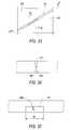
- FIG. 27is a plan view of an exemplary surface covering of the fourth embodiment.
- FIG. 28is an enlarged plan view of a portion of a surface covering of one embodiment of the invention.
- FIG. 29is an enlarged plan view of a portion of FIG. 28 .
- FIG. 30is an enlarged plan view of a second portion of FIG. 28 .
- FIG. 31is a cross-section taken along line 31 - 31 of FIG. 29 .
- FIG. 32is a cross-section taken along line 32 - 32 of FIG. 30 .
- FIG. 33is an enlarged plan view of a portion of a surface covering of the invention.
- FIG. 34is a cross-section taken along line 34 - 34 of FIG. 33 .
- FIG. 35is a cross-section taken along line 35 - 35 of FIG. 33 .
- FIG. 1shows a surface covering 10 constructed in accordance with the present invention.
- Surface covering 10comprises an arrangement of surface covering units without substantial gaps or overlapping.
- substantially gapsmeans comparatively large gaps or spaces that would detract from the appearance of the covered surface.
- without substantial gapsmeans no gaps and/or comparatively small gaps that may be filled with sand or mortar, which do not adversely detract from the appearance of the surface covering.
- unitmeans any surface covering unit, including but not limited to pavers, bricks, tiles, surface molding stamps and other architectural units suitable for use in the construction of floors, work surfaces, walls or other interior or exterior surface coverings.
- Surface covering unitsmay be molded or otherwise made of concrete, stone, ceramics, plastic, natural or synthetic rubber, glass or other suitable material, or combinations thereof.
- surface covering 10is comprised of three different sized units 20 , 40 and 60 . The units have what appear to be irregular configurations. Further, the surface covering 10 has the appearance of a natural, custom stone surface.
- FIG. 2An enlarged view of unit 20 is shown in FIG. 2 .
- the unitcomprises a single primary element 20 of a rotational tessellation as will be described in greater detail below.
- Primary element 20has a first side 22 extending between points A and B.
- Second side 24extends between points A and E.
- a transverse side 26extends between points B and E.
- Transverse side 26preferably comprises a series of segments, namely, a third side 28 extending between points B and C, a fourth side 30 extending between points C and D, and an optional fifth side 32 extending between points D and E.
- First 22 and second 24 sidesare images of one another.
- imagesmeans they have substantially the same shape, that is, the lines formed by sides 22 and 24 have substantially the same configuration so that side 22 on one unit will mate with side 24 of another unit.
- first and second sidesextend radially relative to a common first vertex 34 , and are rotationally spaced by an angle ⁇ .
- Angle ⁇is derived from the formula 360°/n where the variable n is an integer selected from the group of 2, 3, 4 or 6. Thus, angle ⁇ is 60, 90, 120 or 180 degrees. In the example shown in FIG. 2 , the variable n is equal to 6 and ⁇ is 60 degrees.
- the third 28 and fourth 30 sideshave the same shape, a common second vertex 36 , and are rotationally spaced by an angle ⁇ .
- Angle ⁇is derived from the formula 360°/m where the variable m is an integer, and the sum of angle ⁇ and ⁇ is 180, 240, 270 or 300 degrees. In the example shown in FIG. 2 , variable m is 3 and ⁇ is 120°.
- the fifth side 32is optional, that is, the third and fourth sides could extend between points B and E, and thereby complete the circumference of the unit.
- the fifth sideis a substantially straight line in this embodiment.
- first 22 and second 24 sidesare irregular.
- the term “irregular”means that the sides are not straight lines, circular arcs, or other simple geometric shapes. Because first side 22 and second side 24 have substantially the same irregular shape, the first side of one unit will mate with a second side of another unit. Further, because the angle ⁇ is defined as 360°/n, n units may be arranged in a rotational tessellation about first vertex 34 . Similarly, because the angle ⁇ is defined as 360°/m, m units maybe arranged in a rotational tessellation about second vertex 36 .
- FIG. 3illustrates a surface covering 38 formed of a multiplicity of units 20 .
- the first sides 22match and mate with second sides 24 of adjacent units.
- third sides 28match and mate with fourth sides 30 of adjacent units.
- Fifth sidesmate with each other.
- six unitsform a complete rotational tessellation about first vertex points 34 .
- three unitsform a complete rotational tessellation about second vertex points 36 .
- FIG. 4illustrates a second, medium size unit 40 .
- Unit 40comprises two primary elements 20 a and 20 b as indicated by broken line 41 .
- Unit 40has sides that match unit 20 , namely, a first side 42 , second side 44 , and transverse side 46 having third sides 48 , fourth sides 50 and fifth sides 52 .
- Unit 40further includes a first vertex 54 and two second vertices 56 .
- the variable nis 3 and the angle ⁇ between first side 42 and second side 44 is 120°.
- the variable mis three and ⁇ is 120 degrees.
- FIG. 5illustrates a surface covering 58 comprised entirely of second units 40 .
- Three units 40complete a rotational tessellation about vertex 54 .
- Three units 40also comprise a complete rotational tessellation about second vertex 56 .
- FIG. 6illustrates a third or large unit 60 , comprising three primary elements 20 c , 20 d and 20 c as shown by broken lines 61 .
- Unit 60has sides that match units 20 and 40 , namely first side 62 , second side 64 , third sides 68 , fourth sides 70 , and fifth sides 72 .
- Unit 60further includes a first vertex 74 and second vertices 76 .
- the variable nis two and the angle ⁇ between the first side 62 and second side 64 is 180 degrees.
- variable mis 3 and angle ⁇ is 120 degrees.
- FIG. 7illustrates the surface covering 78 comprised entirely of third units 60 .
- Two units 60complete a rotational tessellation about first vertex 74 .
- Three units 60complete a rotational tessellation about second vertices 76 .
- FIGS. 8-10illustrate how surface covering units may be made of different sizes and shapes by combining primary elements 20 .
- unit 80comprises two elements 20 f and 20 g , as reflected by dashed line 81 .
- Unit 80has two first sides 82 , two second sides 84 , a third side 88 , fourth side 90 , and two fifth sides 92 .
- Unit 80has two first vertices 94 and a single second vertex 96 .
- FIG. 9illustrates another unit embodiment 100 comprising three primary elements 20 h , 20 i and 20 j , as shown by broken lines 101 , that are rotationally tessellated about second vertex 104 .
- Unit 100has three first vertices 102 .
- FIG. 10illustrates yet another embodiment 110 comprising three primary elements 20 k , 20 l and 20 m as shown by broken lines 111 .
- Unit 110has two first vertices 112 and two second vertices 114 .
- additional unitsmay be formed in other combinations of primary elements 20 .
- the embodiments shown in FIGS. 8-10are not ideal for construction of concrete pavers due to sharp edges or narrow mid-sections, but are presented to illustrate the concept of different irregular shaped units formed by different combinations of primary elements.
- each rotational tessellationmay contain one or more small 20 , medium 40 or large 60 units, or a combination thereof. Because of the irregularly shaped sides of each unit and the size variations among the units, the surface appears to be natural and custom fitted, that is, a regular geometric pattern is not readily apparent.
- FIG. 1has three different size units, namely, single, double and triple element units, it is contemplated that numerous variations are possible, including, for example, a combination of only units 20 and 40 , or a combination of only units 40 and 60 . Further, it is contemplated that a surface covering could include units 80 , 100 or 110 , or any other units comprised of a combination of primary elements.
- FIGS. 11-16illustrate surface covering units and an exemplary surface covering derived from a second embodiment of a rotational tessellation element of the invention.
- FIG. 11shows a primary element 120 comprised of six sides, namely, first side 122 extending between points A and B, second side 124 extending between points A and F, third side 128 extending between points B and C, fourth side 130 extending between points C and D, fifth side 131 extending between sides D and E and sixth side 133 extending between points E and F. Together, sides 3 to 6 form transverse side 126 .
- Element 120has three vertices, namely, first vertex 134 , second vertex 136 , and third vertex 137 .
- First 122 and second 124 sidesare images of one another, radiate from first vertex 134 , and are rotationally spaced by an angle ⁇ of 60 degrees.
- the third 128 and fourth 130 sidesare images of one another, radiate from second vertex 136 and are rotationally spaced by an angle ⁇ of 180 degrees.
- Fifth 131 and sixth 133 sidesare images of one another, radiate from third vertex 137 and are rotationally spaced by an angle ⁇ of 120 degrees. All six sides are preferably irregular in shape.
- FIG. 12illustrates a unit 140 comprised of two basic elements 120 a and 120 b as indicated by broken lines 141 .
- Elements 120 a and 120 bare adjacent elements in a rotation about first vertex 134 .
- the basic elementsare joined at an interface of first and second sides.
- FIG. 13illustrates a unit 160 comprised of two basic elements 120 c and 120 d as indicated by broken line 161 .
- the basic elementsare joined at an interface of sides three and four.
- Elements 120 c and 120 dshare a second vertex 136 .
- FIG. 14illustrates a unit 180 comprised of three basic elements 120 e , 120 f and 120 g as indicated by broken lines 181 .
- Elements 120 f and 120 gare joined along first-second sides interfaces and share a common first vertex 134 .
- Elements 120 e and 120 fare joined at third-fourth side interfaces and share a common second vertex 136 .
- FIG. 15illustrates a unit 200 comprised of six basic elements 120 h-m as indicated by broken lines 201 .
- First 134 , second 136 and third vertices 137are identified in FIG. 15 .
- unit 200comprises a pair of primary elements from three different rotations about first vertices 134 .
- FIGS. 12-15thus illustrates four ways that basic elements may be combined to form different size and shape units. Additional units may be formed by other combinations of primary element 120 .
- FIG. 16illustrates an exemplary surface covering formed of the units illustrated in FIGS. 11-15 .
- a great variety of surface coveringsmay be formed utilizing combinations of units 120 , 140 , 160 , 180 and 200 , as well as other units formed from different combinations of primary elements of the second embodiment.
- FIGS. 17-22illustrate surface covering units and an exemplary surface covering of a third embodiment of the rotational tessellation element of the invention.
- FIG. 17illustrates a primary element 220 of the third embodiment.
- Primary element 220has a first side 222 extending between points A and B, a second side 224 extending between points A and F.
- the second side 224is a rotated image of first side 222 about first vertex 234 .
- the angle ⁇ of rotationis 90 degrees in the third embodiment.
- Basic element 220further includes third side 228 extending between points B and C and fourth side 230 extending between points C and D.
- Fourth side 230is a rotated image of third side 228 about second vertex 236 .
- the angle of rotation between sides three and fouris angle ⁇ which in case of the third embodiment is 90°.
- Basic element 220further comprises a fifth side 231 extending between points D and E, and a sixth side 233 extending between points E and F.
- Sixth side 233is a rotated image of fifth side 231 about third vertex 237 . The angle of rotation therebetween, ⁇ is 180 degrees.
- FIG. 18illustrates a unit 240 comprised of two primary elements 220 a and 220 b as indicated by broken lines 241 .
- Primary elements 220 a and 220 bare joined at the interface between sides one and two of the respective units, and share a common first vertex 234 .
- FIG. 19is a third unit 260 comprised of three primary elements 220 c , 220 d and 220 e as indicated by broken lines 261 .
- Elements 220 c and 220 dare joined at the interface of sides one and two of adjacent elements, and have a common first vertex 234 .
- Element 220 eis joined to element 220 d at the interface between sides five and six, respectively, and share common third vertex 237 .
- Element 220 eis joined to element 220 c at the interface between sides three and four, respectively and share common second vertex 236 .
- FIG. 20illustrates a unit 280 comprised of four primary elements from the third embodiment, namely elements 220 f , 220 g , 220 h and 220 i as indicated by broken lines 281 . All four elements revolve around first vertex 234 .
- FIG. 21illustrates a fifth unit 300 comprised of four primary elements 220 j-m , as indicated by broken lines 301 .
- unit 300two elements 220 j and 220 k are taken from a rotation about first vertex 234 a .
- Elements 220 l and 220 mcomprise adjacent elements about first vertex 234 b.
- FIG. 22illustrates a surface covering formed from a mixture of units 220 , 240 , 260 , 280 , 300 .
- the surface coveringappears to be irregular, natural and custom made.
- FIGS. 23-27illustrate surface covering units and a surface covering of a fourth embodiment of the rotational tessellation element of the invention.
- FIG. 23illustrates a primary element 320 of the fourth embodiment.
- Primary clement 320has a first side 322 extending between points A and B, a second side 324 extending between points A and F.
- the second side 324is a rotated image of first side 322 about first vertex 334 .
- the angle ⁇ of rotationis 120 degrees in the fourth embodiment.
- Basic element 320further includes a third side 328 extending between points B and C and a fourth side 330 extending between points C and D.
- Fourth side 330is a rotated image of third side 328 about second vertex 336 .
- the angle of rotation between sides 3 and 4is an angle ⁇ , which in the case of the fourth embodiment is 120 degrees.
- Basic element 320further comprises a fifth side 331 extending between points D and E, and a sixth side 333 extending between points E and F.
- Sixth side 333is a rotated image of fifth side 331 , about third vertex 337 .
- the angle of rotation therebetween, ⁇is 120 degrees.
- FIG. 24illustrates a unit 340 comprised of two primary elements 320 a and 320 b as indicated by broken line 341 .
- Basic elements 320 a and 320 bare joined at the interface between sides one and two of adjacent elements, and share a common first vertex 334 .
- FIG. 25is a third unit 360 comprised of two primary elements 320 c and 320 d , as indicated by broken line 361 .
- Elements 320 c and 320 dare joined at the interface of sides three and four of respective elements, and have a common second vertex 336 .
- FIG. 26illustrates a unit 380 comprised of three primary elements from the fourth embodiment, namely, elements 320 e , 320 f and 320 g , as indicated by broken line 381 . All three elements revolve around first vertex 334 .
- FIG. 27illustrates a surface covering formed of a mixture of units 320 , 340 , 360 and 380 . As with the other embodiments the surface covering appears to be natural, irregular and custom made.
- the sum of the vertex angles in embodiments 2-4are all 360 degrees.
- each angle ⁇ , ⁇ and ⁇is evenly divisible into 360 degrees and the sum of the angles is 360 degrees.
- the angles at the respective verticesare not the same.
- the anglesare all the same, namely 120 degrees, in embodiment four.
- Embodiments one, two and three, with different vertex anglesproduce a more irregular and hence more natural looking unit, as compared to embodiment four which appears somewhat hexagonal. Accordingly, it is preferred that at least one of the vertex angles is different than one of the other vertex angles.
- the mating edges of adjacent unitsmatch less than perfectly, i.e., that the line or gap between units vary in thickness. This is preferably accomplished by introducing minor variations in the sides of the units so that the first and second sides are not identical. Likewise, there may be minor variations between the respective shapes of the third and fourth sides, and so on. Variations, however, cannot be so great as to cause problems in mating adjacent units.
- FIGS. 28 and 33illustrate minor variations in the thickness of the gaps 411 , 413 and 451 between adjacent units.
- FIGS. 28-32illustrate one embodiment of such indicia.
- FIG. 28shows units 410 , 412 and 414 , with gaps 411 and 413 therebetween.
- FIG. 29shows an enlarged view of area 416 .
- FIG. 30shows an enlarged view of area 418 .
- FIGS. 28 , 29 and 31show a V-shaped projection 420 from a lower portion of the second side of unit 410 and a corresponding V-shaped recess 422 in the first side of unit 412 .
- each mating projection-recessare uniformly located a consistent radial distance from the applicable vertex.
- the projections and recessesare preferably formed on the lower or inner portions of the units so that they will not be visible in the completed surface covering. Surface construction is facilitated by easily matching V-shaped projections and recesses, and semi-circular projections and recesses, respectively. It should be understood that the particular shape of the projections and recesses depicted in the drawings are merely illustrative and not limiting.
- the projectionsalso function to maintain uniform spacing between adjacent units even when the thickness of the gaps 411 , 413 vary. Proper spacing assists in maintaining the integrity of the surface over large areas.
- FIGS. 33-35illustrate another embodiment of indicia to facilitate construction of surface coverings.
- FIG. 33is a plan view of two adjacent units 450 and 452 with gap 451 therebetween. Each unit includes a lug 454 and 456 , respectively. Mating sides of respective units are desirably provided with lugs of the same size and location. Different mating sides are provided with lugs of a different width “W” or shape. Thereby, mating sides can be easily matched. As with the embodiment of FIGS. 28-32 , the lugs function to maintain uniform spacing between members despite variations in the width of the gap 451 .
- the lugsmay be provided with other indicia such as, letters, numbers or symbols to facilitate matching as shown for example at reference numeral 456 in FIG. 35 .
- Dyes and colorantsmay be added to the units, and the color and quantity of dye may be regulated to produce color variations from unit to unit.
- Surface variations from unit to unitare also desirable.
- One method of introducing surface variationis to tumble the units after curing. Tumbled units and methods for tumbling are well known in the art.
- An alternative methodis to hammer the surface of the unit to create small nicks or marks.
- Surface variationsalso may be made in the molds. For example, in a six form assembly, each mold can include a different surface irregularity or variation. Thereby, only every sixth unit would be the same.
- the surface covering units of the inventionmay be made in any conventional manner, in the case of pavers, preferably by molding.
- paverspreferably by molding.
- a preferred dry cast methodis slip-form molding from dry mix concrete to form pavers suited for use in walkways, driveways and patios.
- a formIn the wet cast process, a form is constructed with side walls conforming to the planar configuration of the unit (as discussed above) with a bottom of the form designed to mold what will be the outer or top surface of the unit.
- the paveris molded upside down by pouring a concrete mixture into the form and allowing it to cure.
- Another form of surface covering units of the inventioncomprises molding stamps, each stamp being comprised of one or more primary elements.
- Molding stampsare known to persons skilled in the art. Generally, a surface is formed by pouring, spreading and leveling concrete. While the surface is wet (uncured) molding stamps are pressed into the surface, the surface being molded to conform to the stamp. In forming a stamp molded surface at least one stamp is required, but preferably several stamps are used, including stamps of different sizes and/or shapes resulting from different combinations of primary elements. The stamp molds are aligned and mated one to another in the same manner as described above in reference to pavers. The finished surface has a natural stone appearance, but is actually a concrete slab.
Landscapes
- Engineering & Computer Science (AREA)
- Architecture (AREA)
- Civil Engineering (AREA)
- Structural Engineering (AREA)
- Finishing Walls (AREA)
- Radiation-Therapy Devices (AREA)
- Floor Finish (AREA)
Abstract
Description
| EMBODI- | ANGLE | ANGLE | ANGLE | |
| MENT | θ | φ | γ | TOTAL |
| 2 | 60 | 180 | 120 | 360 |
| 3 | 90 | 90 | 180 | 360 |
| 4 | 120 | 120 | 120 | 360 |
Claims (21)
Priority Applications (19)
| Application Number | Priority Date | Filing Date | Title |
|---|---|---|---|
| US10/395,537US6881463B2 (en) | 2003-03-24 | 2003-03-24 | Irregular, rotational tessellation surface covering units and surface covering |
| MXPA05009901AMXPA05009901A (en) | 2003-03-24 | 2004-03-24 | Irregular tessellated building units. |
| AU2004223326AAU2004223326B2 (en) | 2003-03-24 | 2004-03-24 | Irregular tessellated building units |
| EP12153384.8AEP2487310A3 (en) | 2003-03-24 | 2004-03-24 | Irregular tessellated building units |
| US10/550,121US7393155B2 (en) | 2003-03-24 | 2004-03-24 | Irregular tessellated building units |
| EP12153381.4AEP2487295B1 (en) | 2003-03-24 | 2004-03-24 | Irregular tessellated building units |
| EP04758137AEP1606467A4 (en) | 2003-03-24 | 2004-03-24 | Irregular tessellated building units |
| PCT/US2004/009148WO2004085755A2 (en) | 2003-03-24 | 2004-03-24 | Irregular tessellated building units |
| CA002519296ACA2519296C (en) | 2003-03-24 | 2004-03-24 | Irregular tessellated building units |
| EP12153380.6AEP2472016A3 (en) | 2003-03-24 | 2004-03-24 | Irregular tessellated building units |
| CA2669451ACA2669451C (en) | 2003-03-24 | 2004-03-24 | Irregular tessellated building units |
| CA2669449ACA2669449C (en) | 2003-03-24 | 2004-03-24 | Irregular tessellated building units |
| EP12153383.0AEP2472017B1 (en) | 2003-03-24 | 2004-03-24 | Irregular tessellated building units |
| US12/689,062US7993718B2 (en) | 2003-03-24 | 2010-01-18 | Irregular tessellated building units |
| US13/205,161US8298641B2 (en) | 2003-03-24 | 2011-08-08 | Irregular tessellated building units |
| US13/626,443US8609215B2 (en) | 2003-03-24 | 2012-09-25 | Irregular tessellated building units |
| US14/052,161US8888401B2 (en) | 2003-03-24 | 2013-10-11 | Irregular tessellated building units |
| US14/537,997US9428906B2 (en) | 2003-03-24 | 2014-11-11 | Irregular tessellated building units |
| US15/221,767US9745742B2 (en) | 2003-03-24 | 2016-07-28 | Irregular tessellated building units |
Applications Claiming Priority (1)
| Application Number | Priority Date | Filing Date | Title |
|---|---|---|---|
| US10/395,537US6881463B2 (en) | 2003-03-24 | 2003-03-24 | Irregular, rotational tessellation surface covering units and surface covering |
Related Child Applications (5)
| Application Number | Title | Priority Date | Filing Date |
|---|---|---|---|
| PCT/US2004/009148Continuation-In-PartWO2004085755A2 (en) | 2003-03-24 | 2004-03-24 | Irregular tessellated building units |
| PCT/US2004/009148ContinuationWO2004085755A2 (en) | 2003-03-24 | 2004-03-24 | Irregular tessellated building units |
| US10550121Continuation-In-Part | 2004-03-24 | ||
| US10550121Continuation | 2004-03-24 | ||
| US10/550,121Continuation-In-PartUS7393155B2 (en) | 2003-03-24 | 2004-03-24 | Irregular tessellated building units |
Publications (2)
| Publication Number | Publication Date |
|---|---|
| US20040191461A1 US20040191461A1 (en) | 2004-09-30 |
| US6881463B2true US6881463B2 (en) | 2005-04-19 |
Family
ID=32988597
Family Applications (1)
| Application Number | Title | Priority Date | Filing Date |
|---|---|---|---|
| US10/395,537Expired - LifetimeUS6881463B2 (en) | 2003-03-24 | 2003-03-24 | Irregular, rotational tessellation surface covering units and surface covering |
Country Status (2)
| Country | Link |
|---|---|
| US (1) | US6881463B2 (en) |
| EP (4) | EP2487310A3 (en) |
Cited By (52)
| Publication number | Priority date | Publication date | Assignee | Title |
|---|---|---|---|---|
| USD522667S1 (en)* | 2004-11-18 | 2006-06-06 | Oldcastle Building Products Canada Inc. | Artificial stone |
| US20060157634A1 (en)* | 2004-12-14 | 2006-07-20 | Nasvik Paul C | Form liner for creating a realistic stone wall pattern |
| US20060182923A1 (en)* | 2003-03-24 | 2006-08-17 | Riccobene Thomas S | Irregular tessellated building units |
| USD536058S1 (en) | 2004-06-04 | 2007-01-30 | Riccobene Designs Llc | Landscape stone |
| USD537959S1 (en) | 2004-12-01 | 2007-03-06 | Oldcastle Building Products Canada Inc. | Artificial stone |
| US20070077387A1 (en)* | 2003-09-18 | 2007-04-05 | Riccobene Design Llc | Irregular, tessellated building units |
| USD541435S1 (en)* | 2006-03-31 | 2007-04-24 | Wissman Donald W | Tessellatable brick |
| USD541436S1 (en)* | 2006-02-17 | 2007-04-24 | Wissman Donald W | Tessellatable brick |
| USD543642S1 (en)* | 2004-11-18 | 2007-05-29 | Oldcastle Building Products Canada, Ltd. | Artificial stone |
| US20070167231A1 (en)* | 2004-08-13 | 2007-07-19 | Nhn Corporation, A Corporation | Method and system for renewing screen using mechanics information |
| US20070217865A1 (en)* | 2004-10-25 | 2007-09-20 | Oldcastle Building Products Canada, Inc. | Artificial Flagstone For Providing A Surface With A Natural Random Look |
| US20070289247A1 (en)* | 2006-06-14 | 2007-12-20 | Denis Hamel | Dry-cast concrete blocks and manufacturing process therefor |
| US20080095577A1 (en)* | 2006-10-19 | 2008-04-24 | Rene Brun | Modular surface element |
| US20080145148A1 (en)* | 2006-12-15 | 2008-06-19 | Denis Hamel | Dry-cast concrete block |
| USD577130S1 (en) | 2006-12-06 | 2008-09-16 | Transpavé Inc. | Dry-cast concrete block |
| US20080240857A1 (en)* | 2007-03-28 | 2008-10-02 | Joseph Ciccarello | Irregularly shaped hexagonal paving stone with integral mating spacers |
| US20090016849A1 (en)* | 2007-07-13 | 2009-01-15 | Riccobene Designs Llc | Landscape retaining stake |
| USD586925S1 (en)* | 2006-07-27 | 2009-02-17 | Riccobene Designs Llc | Landscape stone |
| USD590070S1 (en) | 2007-08-02 | 2009-04-07 | Oldcastle Building Products Canada Inc. | Artificial slab |
| USD590072S1 (en) | 2007-08-02 | 2009-04-07 | Oldcastle Building Products Canada Inc. | Artificial slab |
| USD590071S1 (en) | 2007-08-02 | 2009-04-07 | Oldcastle Building Products Canada Inc. | Artificial slab |
| USD601267S1 (en) | 2007-05-15 | 2009-09-29 | Les Materiaux De Construction Oldcastle Canada, Inc. | Paving stone |
| USD624203S1 (en) | 2005-12-14 | 2010-09-21 | Les Materiaux De Construction Oldcastle Canada Inc. | Top edge portion of a mini random look paver |
| US20100307092A1 (en)* | 2007-09-26 | 2010-12-09 | Oldcastle Building Products Canada, Inc. | Covering Unit |
| US20100322709A1 (en)* | 2009-06-22 | 2010-12-23 | Charles Ciccarello | Paving stone and method |
| US20110067333A1 (en)* | 2008-05-21 | 2011-03-24 | Marc-Andre Lacas | Artificial stone |
| USD643544S1 (en)* | 2010-03-02 | 2011-08-16 | Marcel Thomassen | Set of blocks |
| USD643547S1 (en)* | 2009-06-08 | 2011-08-16 | Justin Louis K | Inlay piece set |
| US8298641B2 (en) | 2003-03-24 | 2012-10-30 | Keystone Retaining Wall Systems, Inc. | Irregular tessellated building units |
| US8336274B2 (en)* | 2010-10-20 | 2012-12-25 | Keystone Retaining Wall Systems Llc | Irregular building units having mating sides |
| USD686346S1 (en) | 2012-12-21 | 2013-07-16 | Keystone Retaining Wall Systems Llc | Landscape stone |
| USD695920S1 (en) | 2012-09-05 | 2013-12-17 | Oldcastle Building Products Canada, Inc. | Paver |
| USD695918S1 (en) | 2012-09-05 | 2013-12-17 | Oldcastle Building Products Canada, Inc. | Paver |
| USD695917S1 (en) | 2012-09-05 | 2013-12-17 | Oldcastle Building Products Canada, Inc. | Paver |
| USD695915S1 (en) | 2012-09-05 | 2013-12-17 | Oldcastle Building Products Canada, Inc. | Paver |
| USD695919S1 (en) | 2012-09-05 | 2013-12-17 | Oldcastle Building Products Canada, Inc. | Paver |
| USD695921S1 (en) | 2012-09-05 | 2013-12-17 | Oldcastle Building Products Canada, Inc. | Paver |
| USD695922S1 (en) | 2012-09-05 | 2013-12-17 | Oldcastle Building Products Canada, Inc. | Paver |
| USD695916S1 (en) | 2012-09-05 | 2013-12-17 | Oldcastle Building Products Canada, Inc. | Paver |
| US8713295B2 (en) | 2004-07-12 | 2014-04-29 | Oracle International Corporation | Fabric-backplane enterprise servers with pluggable I/O sub-system |
| US8743872B2 (en) | 2004-02-13 | 2014-06-03 | Oracle International Corporation | Storage traffic communication via a switch fabric in accordance with a VLAN |
| US8848727B2 (en) | 2004-02-13 | 2014-09-30 | Oracle International Corporation | Hierarchical transport protocol stack for data transfer between enterprise servers |
| US8868790B2 (en) | 2004-02-13 | 2014-10-21 | Oracle International Corporation | Processor-memory module performance acceleration in fabric-backplane enterprise servers |
| US9315950B2 (en) | 2012-10-19 | 2016-04-19 | Oldcastle Architectural, Inc. | Paving stones |
| US9404226B2 (en) | 2012-06-18 | 2016-08-02 | Oldcastle Building Products Canada Inc. | Dual-unit paving system |
| US20170114504A1 (en)* | 2015-10-21 | 2017-04-27 | Pavestone, LLC | Paving system |
| US10370859B2 (en) | 2015-07-22 | 2019-08-06 | Keystone Retaining Wall Systems Llc | Patio blocks and block systems with side surface positioning and retaining structures |
| US20200024850A1 (en)* | 2018-07-19 | 2020-01-23 | Quarry Ridge Stone, Inc. | Decorative masonry system |
| US10583588B2 (en) | 2013-06-21 | 2020-03-10 | Pavestone, LLC | Manufactured retaining wall block with improved false joint |
| USD893759S1 (en) | 2018-02-08 | 2020-08-18 | Mdc Contracting, Llc | Landscape slab |
| US20220267965A1 (en)* | 2021-02-24 | 2022-08-25 | Michael Allan WELSH | Methods For Preparing and Installing a Natural Stone Surface and a Tiled Natural Stone Paving System Therefor |
| US20230383544A1 (en)* | 2023-07-06 | 2023-11-30 | Chunli Du | Periodic and nonperiodic tiling system based on regular hexagons |
Families Citing this family (17)
| Publication number | Priority date | Publication date | Assignee | Title |
|---|---|---|---|---|
| SE9500810D0 (en) | 1995-03-07 | 1995-03-07 | Perstorp Flooring Ab | Floor tile |
| US7131242B2 (en) | 1995-03-07 | 2006-11-07 | Pergo (Europe) Ab | Flooring panel or wall panel and use thereof |
| US7992358B2 (en) | 1998-02-04 | 2011-08-09 | Pergo AG | Guiding means at a joint |
| SE514645C2 (en) | 1998-10-06 | 2001-03-26 | Perstorp Flooring Ab | Floor covering material comprising disc-shaped floor elements intended to be joined by separate joint profiles |
| US7877956B2 (en)* | 1999-07-05 | 2011-02-01 | Pergo AG | Floor element with guiding means |
| SE518184C2 (en) | 2000-03-31 | 2002-09-03 | Perstorp Flooring Ab | Floor covering material comprising disc-shaped floor elements which are joined together by means of interconnecting means |
| CA2387181A1 (en) | 2002-05-22 | 2003-11-22 | Les Materiaux De Construction Oldcastle Canada Inc. | An artificial piece of masonry and a kit for forming a masonry wall |
| CA2544152C (en)* | 2005-04-21 | 2013-06-11 | Les Materiaux De Construction Oldcastle Canada Inc./ Oldcastle Building Products Canada Inc. | Improvement in a molding apparatus for producing dry cast products having textured side surfaces |
| TWI278295B (en)* | 2006-07-07 | 2007-04-11 | Ming-Guei Wang | Corner paintbrush |
| GB0616097D0 (en)* | 2006-08-15 | 2006-09-20 | Dynamic Geometry Ltd | Tessellating elements |
| DE102010004717A1 (en) | 2010-01-15 | 2011-07-21 | Pergo (Europe) Ab | Set of panels comprising retaining profiles with a separate clip and method for introducing the clip |
| CN104831904B (en) | 2010-05-10 | 2017-05-24 | 佩尔戈(欧洲)股份公司 | Set of panels |
| US9739028B2 (en) | 2013-03-15 | 2017-08-22 | Keystone Retaining Wall Systems Llc | Irregular trapezoidal building unit and wall structure including same |
| US9021761B2 (en) | 2013-03-15 | 2015-05-05 | Keystone Retaining Wall Systems Llc | Building unit with mating sides |
| FR3020011B1 (en)* | 2014-04-16 | 2018-11-23 | Novaltess | METHOD FOR PRODUCING A MOSAIC AND TILES FOR IMPLEMENTING THE METHOD |
| WO2016098051A1 (en) | 2014-12-17 | 2016-06-23 | Dayco Europe S.R.L. | Tensioner for an accessory drive |
| US11498357B2 (en)* | 2019-06-20 | 2022-11-15 | Certainteed Llc | Randomized surface panel kit and surface panel system |
Citations (11)
| Publication number | Priority date | Publication date | Assignee | Title |
|---|---|---|---|---|
| US4217740A (en) | 1978-06-07 | 1980-08-19 | Assanti Philip N | Variable mosaic pattern with interchangeable components |
| DE4232300A1 (en) | 1992-09-26 | 1994-03-31 | Sf Koop Gmbh Beton Konzepte | Concrete pavement slab with vertical side faces - has three or more corners in plan view with vertical corner edges, coupled by side faces |
| DE4333942A1 (en) | 1993-10-06 | 1995-04-13 | Sf Koop Gmbh Beton Konzepte | Construction set of shaped concrete blocks and device for producing the same |
| US5486066A (en) | 1991-11-23 | 1996-01-23 | Sf-Kooperation Gmbh Beton Konzepte | Paving stone set and process and device for the manufacture thereof |
| US5524396A (en) | 1993-06-10 | 1996-06-11 | Lalvani; Haresh | Space structures with non-periodic subdivisions of polygonal faces |
| US5597591A (en) | 1994-01-27 | 1997-01-28 | Sf-Kooperation Gmbh Beton-Konzepte | Apparatus for the production of concrete paving stones |
| US5945181A (en) | 1995-10-14 | 1999-08-31 | Fisher; Adrian | Tessellatable elements and plane tessellations for covering or decoration |
| DE10001967A1 (en) | 2000-01-18 | 2001-07-19 | Sf Koop Gmbh Beton Konzepte | Paving stone set for ground cover uses two groups of stones differing in plane and joined at gaps defined by spacers all round to give regular raster of as-laid stones. |
| US6263633B1 (en) | 1997-10-27 | 2001-07-24 | Sf-Kooperation Gmbh Beton-Konzepte | Paving stone, set of paving stones and device for producing the same |
| WO2001053612A1 (en) | 2000-01-20 | 2001-07-26 | Sf-Kooperation Gmbh Beton-Konzepte | Moulded brick made of concrete, mould and method for producing a moulded brick |
| USD480819S1 (en) | 2003-02-14 | 2003-10-14 | Cyrille J. Barbier | Leaf paver |
Family Cites Families (12)
| Publication number | Priority date | Publication date | Assignee | Title |
|---|---|---|---|---|
| GB1094632A (en)* | 1966-03-25 | 1967-12-13 | Bert Brierley | Improvements in or relating to tiles or slabs |
| US3947192A (en)* | 1974-11-15 | 1976-03-30 | Hugo Rosenberger | Paving block |
| GB1548164A (en)* | 1975-06-25 | 1979-07-04 | Penrose R | Set of tiles for covering a surface |
| ATE94927T1 (en)* | 1989-10-24 | 1993-10-15 | Rolf Scheiwiller | CONNECTING STONES. |
| US5108219A (en)* | 1990-12-14 | 1992-04-28 | Hair Roberta A | Interlocking paving stone |
| US5267810A (en)* | 1991-09-25 | 1993-12-07 | Johnson Christopher M | Paving block |
| US5619830A (en)* | 1995-03-13 | 1997-04-15 | Osborn; John A. L. | Variably assemblable figurative tiles for games, puzzles, and for covering surfaces |
| US5520388A (en)* | 1995-05-16 | 1996-05-28 | Osborn; John A. L. | Single-shape variably assemblable figurative tiles for games, puzzles, and for convering surfaces |
| PL195987B1 (en)* | 1998-08-17 | 2007-11-30 | Rolf Scheiwiller | Paving stone |
| DE29922003U1 (en)* | 1999-12-15 | 2000-02-17 | KANN GmbH Baustoffwerke, 56170 Bendorf | Artificial stone component |
| JP2002285504A (en)* | 2001-03-22 | 2002-10-03 | Nihon Kogyo Co Ltd | Block for pavement and laying method |
| AU745257B3 (en)* | 2001-05-07 | 2002-03-14 | Advanced Image Research Pty Ltd | Game and tile set |
- 2003
- 2003-03-24USUS10/395,537patent/US6881463B2/ennot_activeExpired - Lifetime
- 2004
- 2004-03-24EPEP12153384.8Apatent/EP2487310A3/ennot_activeWithdrawn
- 2004-03-24EPEP12153381.4Apatent/EP2487295B1/ennot_activeExpired - Lifetime
- 2004-03-24EPEP12153383.0Apatent/EP2472017B1/ennot_activeExpired - Lifetime
- 2004-03-24EPEP12153380.6Apatent/EP2472016A3/ennot_activeWithdrawn
Patent Citations (12)
| Publication number | Priority date | Publication date | Assignee | Title |
|---|---|---|---|---|
| US4217740A (en) | 1978-06-07 | 1980-08-19 | Assanti Philip N | Variable mosaic pattern with interchangeable components |
| US5486066A (en) | 1991-11-23 | 1996-01-23 | Sf-Kooperation Gmbh Beton Konzepte | Paving stone set and process and device for the manufacture thereof |
| US5588775A (en) | 1991-11-23 | 1996-12-31 | Sf-Kooperation Gmbh Beton-Konzepte | Paving stone set and process and device for the manufacture thereof |
| DE4232300A1 (en) | 1992-09-26 | 1994-03-31 | Sf Koop Gmbh Beton Konzepte | Concrete pavement slab with vertical side faces - has three or more corners in plan view with vertical corner edges, coupled by side faces |
| US5524396A (en) | 1993-06-10 | 1996-06-11 | Lalvani; Haresh | Space structures with non-periodic subdivisions of polygonal faces |
| DE4333942A1 (en) | 1993-10-06 | 1995-04-13 | Sf Koop Gmbh Beton Konzepte | Construction set of shaped concrete blocks and device for producing the same |
| US5597591A (en) | 1994-01-27 | 1997-01-28 | Sf-Kooperation Gmbh Beton-Konzepte | Apparatus for the production of concrete paving stones |
| US5945181A (en) | 1995-10-14 | 1999-08-31 | Fisher; Adrian | Tessellatable elements and plane tessellations for covering or decoration |
| US6263633B1 (en) | 1997-10-27 | 2001-07-24 | Sf-Kooperation Gmbh Beton-Konzepte | Paving stone, set of paving stones and device for producing the same |
| DE10001967A1 (en) | 2000-01-18 | 2001-07-19 | Sf Koop Gmbh Beton Konzepte | Paving stone set for ground cover uses two groups of stones differing in plane and joined at gaps defined by spacers all round to give regular raster of as-laid stones. |
| WO2001053612A1 (en) | 2000-01-20 | 2001-07-26 | Sf-Kooperation Gmbh Beton-Konzepte | Moulded brick made of concrete, mould and method for producing a moulded brick |
| USD480819S1 (en) | 2003-02-14 | 2003-10-14 | Cyrille J. Barbier | Leaf paver |
Non-Patent Citations (12)
| Title |
|---|
| Beautiful Edgers; Pavestone Brochure Published 2002. |
| Concrete Landscaping/PRODUCTS; Old Castle Brochure; Published 2002. |
| Designing Tessellations: The Secrets of Interlocking Patterns: Author: Jinny Beyer: Chapter 7: The Keys to Creating Interlocking Tessellations: p. 125-153 1999. |
| Nature Walk(TM) Natural Flagstone Appeal for Pedestrian Traffic 2001. |
| Retaining Walls; Pavestone Brochure Published 2002. |
| Website: www.geckostone.com Geckostone(TM) 3/03. |
| Website: www.learningcompanyschool.com TesselMania! Deluxe 6/03. |
| Website: www.matfcrete.net/RandonStone.htm MATCRETE The Ultimate in Concrete Design 12/02. |
| Website: www.mathforum.org/sum95.suzanne/whattess.html What is Tessellation? 4/02. |
| Website: www.riverdeep.net/products/other/tesselmania.jhtml TesselMania ! Deluxe 6/03. |
| Website: www.sf-kooperation.de/english/index Canteon(R): CIS 300-10; Pentalith 7/2001. |
| Website: www.superstone.com SPLIT ROCK 12/02. |
Cited By (96)
| Publication number | Priority date | Publication date | Assignee | Title |
|---|---|---|---|---|
| US7393155B2 (en) | 2003-03-24 | 2008-07-01 | Riccobene Designs Llc | Irregular tessellated building units |
| US8298641B2 (en) | 2003-03-24 | 2012-10-30 | Keystone Retaining Wall Systems, Inc. | Irregular tessellated building units |
| US20060182923A1 (en)* | 2003-03-24 | 2006-08-17 | Riccobene Thomas S | Irregular tessellated building units |
| US9745742B2 (en) | 2003-03-24 | 2017-08-29 | Keystone Retaining Wall Systems Llc | Irregular tessellated building units |
| US7993718B2 (en) | 2003-03-24 | 2011-08-09 | Keystone Retaining Wall Systems, Inc. | Irregular tessellated building units |
| US20100115859A1 (en)* | 2003-03-24 | 2010-05-13 | Riccobene Designs Llc | Irregular tessellated building units |
| US9428906B2 (en) | 2003-03-24 | 2016-08-30 | Keystone Retaining Wall Systems Llc | Irregular tessellated building units |
| US8609215B2 (en) | 2003-03-24 | 2013-12-17 | Keystone Retaining Wall Systems Llc | Irregular tessellated building units |
| US8888401B2 (en) | 2003-03-24 | 2014-11-18 | Keystone Retaining Wall Systems Llc | Irregular tessellated building units |
| US20070098945A2 (en)* | 2003-03-24 | 2007-05-03 | Riccobene Designs Llc | Irregular Tessellated Building Units |
| US7674067B2 (en) | 2003-09-18 | 2010-03-09 | Riccobene Designs Llc | Irregular tessellated building units |
| US20070077387A1 (en)* | 2003-09-18 | 2007-04-05 | Riccobene Design Llc | Irregular, tessellated building units |
| US20080209828A1 (en)* | 2003-09-18 | 2008-09-04 | Riccobene Designs Llc | Irregular tessellated building units |
| US8868790B2 (en) | 2004-02-13 | 2014-10-21 | Oracle International Corporation | Processor-memory module performance acceleration in fabric-backplane enterprise servers |
| US8848727B2 (en) | 2004-02-13 | 2014-09-30 | Oracle International Corporation | Hierarchical transport protocol stack for data transfer between enterprise servers |
| US8743872B2 (en) | 2004-02-13 | 2014-06-03 | Oracle International Corporation | Storage traffic communication via a switch fabric in accordance with a VLAN |
| USD536058S1 (en) | 2004-06-04 | 2007-01-30 | Riccobene Designs Llc | Landscape stone |
| USD537501S1 (en)* | 2004-06-04 | 2007-02-27 | Riccobene Designs Llc | Landscape stone |
| US8713295B2 (en) | 2004-07-12 | 2014-04-29 | Oracle International Corporation | Fabric-backplane enterprise servers with pluggable I/O sub-system |
| US20070167231A1 (en)* | 2004-08-13 | 2007-07-19 | Nhn Corporation, A Corporation | Method and system for renewing screen using mechanics information |
| US20100236174A1 (en)* | 2004-10-25 | 2010-09-23 | Oldcastle Building Products Canada, Inc. | Artificial flagstone for providing a surface with a natural random look |
| US9534396B2 (en) | 2004-10-25 | 2017-01-03 | Oldcastle Building Products Canada, Inc. | Artificial flagstone for providing a surface with a natural random look |
| US8967907B2 (en) | 2004-10-25 | 2015-03-03 | Oldcastle Building Products Canada, Inc. | Artificial flagstone for providing a surface with a natural random look |
| US8500361B2 (en) | 2004-10-25 | 2013-08-06 | Oldcastle Building Products Canada, Inc. | Artificial flagstone for providing a surface with a natural random look |
| US9193215B2 (en) | 2004-10-25 | 2015-11-24 | Oldcastle Building Products Canada, Inc. | Artificial flagstone for providing a surface with a natural random look |
| US8337116B2 (en) | 2004-10-25 | 2012-12-25 | Oldcastle Building Products Canada, Inc. | Artificial flagstone for providing a surface with a natural random look |
| US8132981B2 (en) | 2004-10-25 | 2012-03-13 | Oldcastle Building Products Canada, Inc. | Artificial flagstone for providing a surface with a natural random look |
| US20070217865A1 (en)* | 2004-10-25 | 2007-09-20 | Oldcastle Building Products Canada, Inc. | Artificial Flagstone For Providing A Surface With A Natural Random Look |
| US10240301B2 (en) | 2004-10-25 | 2019-03-26 | Oldcastle Building Products Canada, Inc. | Artificial flagstone for providing a surface with a natural random look |
| US8747019B2 (en) | 2004-10-25 | 2014-06-10 | Oldcastle Building Products Canada, Inc. | Artificial flagstone for providing a surface with a natural random look |
| US7988382B2 (en) | 2004-10-25 | 2011-08-02 | Oldcastle Building Products Canada, Inc. | Artificial flagstone for providing a surface with a natural random look |
| US9677228B2 (en) | 2004-10-25 | 2017-06-13 | Oldcastle Building Products Canada Inc. | Artificial flagstone for providing a surface with a natural random look |
| USD553260S1 (en)* | 2004-11-18 | 2007-10-16 | Oldcastle Building Products Canada, Inc. | Artificial stone |
| USD522667S1 (en)* | 2004-11-18 | 2006-06-06 | Oldcastle Building Products Canada Inc. | Artificial stone |
| USD543642S1 (en)* | 2004-11-18 | 2007-05-29 | Oldcastle Building Products Canada, Ltd. | Artificial stone |
| USD537959S1 (en) | 2004-12-01 | 2007-03-06 | Oldcastle Building Products Canada Inc. | Artificial stone |
| US7527236B2 (en)* | 2004-12-14 | 2009-05-05 | Nasvik Paul C | Form liner with connection regions having a plurality of linear segments for creating a realistic stone wall pattern |
| US20060157634A1 (en)* | 2004-12-14 | 2006-07-20 | Nasvik Paul C | Form liner for creating a realistic stone wall pattern |
| USD624202S1 (en) | 2005-12-14 | 2010-09-21 | Les Materiaux De Construction Oldcastle Canada Inc. | Top edge portion of a mini random look paver |
| USD624203S1 (en) | 2005-12-14 | 2010-09-21 | Les Materiaux De Construction Oldcastle Canada Inc. | Top edge portion of a mini random look paver |
| USD541436S1 (en)* | 2006-02-17 | 2007-04-24 | Wissman Donald W | Tessellatable brick |
| USD541435S1 (en)* | 2006-03-31 | 2007-04-24 | Wissman Donald W | Tessellatable brick |
| US20070289247A1 (en)* | 2006-06-14 | 2007-12-20 | Denis Hamel | Dry-cast concrete blocks and manufacturing process therefor |
| US8844228B2 (en)* | 2006-06-14 | 2014-09-30 | Oldcastle Building Products Canada, Inc. | Dry-cast concrete block |
| USD586925S1 (en)* | 2006-07-27 | 2009-02-17 | Riccobene Designs Llc | Landscape stone |
| WO2008046224A1 (en)* | 2006-10-19 | 2008-04-24 | Brun Rene | Modular surface element |
| US20080095577A1 (en)* | 2006-10-19 | 2008-04-24 | Rene Brun | Modular surface element |
| USD577130S1 (en) | 2006-12-06 | 2008-09-16 | Transpavé Inc. | Dry-cast concrete block |
| US7850393B2 (en)* | 2006-12-15 | 2010-12-14 | Transpavé Inc. | Dry-cast concrete block |
| US20080145148A1 (en)* | 2006-12-15 | 2008-06-19 | Denis Hamel | Dry-cast concrete block |
| US20080240857A1 (en)* | 2007-03-28 | 2008-10-02 | Joseph Ciccarello | Irregularly shaped hexagonal paving stone with integral mating spacers |
| USD601267S1 (en) | 2007-05-15 | 2009-09-29 | Les Materiaux De Construction Oldcastle Canada, Inc. | Paving stone |
| US20090016849A1 (en)* | 2007-07-13 | 2009-01-15 | Riccobene Designs Llc | Landscape retaining stake |
| USD590070S1 (en) | 2007-08-02 | 2009-04-07 | Oldcastle Building Products Canada Inc. | Artificial slab |
| USD590072S1 (en) | 2007-08-02 | 2009-04-07 | Oldcastle Building Products Canada Inc. | Artificial slab |
| USD590071S1 (en) | 2007-08-02 | 2009-04-07 | Oldcastle Building Products Canada Inc. | Artificial slab |
| US8226323B2 (en) | 2007-09-26 | 2012-07-24 | Oldcastle Building Products Canada, Inc. | Covering unit |
| US8668404B2 (en) | 2007-09-26 | 2014-03-11 | Oldcastle Building Products Canada, Inc. | Covering unit |
| US20100307092A1 (en)* | 2007-09-26 | 2010-12-09 | Oldcastle Building Products Canada, Inc. | Covering Unit |
| US8413397B2 (en) | 2008-05-21 | 2013-04-09 | Oldcastle Building Products Canada Inc. | Artificial stone |
| US8769896B2 (en) | 2008-05-21 | 2014-07-08 | Oldcastle Building Products Canada, Inc. | Artificial stone |
| US9057197B2 (en) | 2008-05-21 | 2015-06-16 | Oldcastle Building Products Canada, Inc. | Artificial stone |
| US20110067333A1 (en)* | 2008-05-21 | 2011-03-24 | Marc-Andre Lacas | Artificial stone |
| USD643547S1 (en)* | 2009-06-08 | 2011-08-16 | Justin Louis K | Inlay piece set |
| US20100322709A1 (en)* | 2009-06-22 | 2010-12-23 | Charles Ciccarello | Paving stone and method |
| US8002494B2 (en)* | 2009-06-22 | 2011-08-23 | Techo-Bloc Inc. | Paving stone and method |
| USD643544S1 (en)* | 2010-03-02 | 2011-08-16 | Marcel Thomassen | Set of blocks |
| US8726595B2 (en) | 2010-10-20 | 2014-05-20 | Keystone Retaining Wall Systems Llc | Irregular building units having mating sides |
| US8336274B2 (en)* | 2010-10-20 | 2012-12-25 | Keystone Retaining Wall Systems Llc | Irregular building units having mating sides |
| US10087585B2 (en) | 2012-06-18 | 2018-10-02 | Oldcastle Building Products Canada Inc. | Dual-unit paving system |
| US9752288B2 (en) | 2012-06-18 | 2017-09-05 | Oldcastle Building Products Canada Inc. | Dual-unit paving system |
| US9404226B2 (en) | 2012-06-18 | 2016-08-02 | Oldcastle Building Products Canada Inc. | Dual-unit paving system |
| US10337152B2 (en) | 2012-06-18 | 2019-07-02 | Oldcastle Building Products Canada Inc. | Dual-unit paving system |
| USD695920S1 (en) | 2012-09-05 | 2013-12-17 | Oldcastle Building Products Canada, Inc. | Paver |
| USD695921S1 (en) | 2012-09-05 | 2013-12-17 | Oldcastle Building Products Canada, Inc. | Paver |
| USD695922S1 (en) | 2012-09-05 | 2013-12-17 | Oldcastle Building Products Canada, Inc. | Paver |
| USD695916S1 (en) | 2012-09-05 | 2013-12-17 | Oldcastle Building Products Canada, Inc. | Paver |
| USD695919S1 (en) | 2012-09-05 | 2013-12-17 | Oldcastle Building Products Canada, Inc. | Paver |
| USD695918S1 (en) | 2012-09-05 | 2013-12-17 | Oldcastle Building Products Canada, Inc. | Paver |
| USD695917S1 (en) | 2012-09-05 | 2013-12-17 | Oldcastle Building Products Canada, Inc. | Paver |
| USD695915S1 (en) | 2012-09-05 | 2013-12-17 | Oldcastle Building Products Canada, Inc. | Paver |
| US10081918B2 (en) | 2012-10-19 | 2018-09-25 | Oldcastle Architectural, Inc. | Paving stones |
| US9315950B2 (en) | 2012-10-19 | 2016-04-19 | Oldcastle Architectural, Inc. | Paving stones |
| US9840813B2 (en) | 2012-10-19 | 2017-12-12 | Oldcastle Architectural, Inc. | Paving stones |
| USD686346S1 (en) | 2012-12-21 | 2013-07-16 | Keystone Retaining Wall Systems Llc | Landscape stone |
| US11801622B2 (en) | 2013-06-21 | 2023-10-31 | Pavestone, LLC | Manufactured retaining wall block with improved false joint |
| US10583588B2 (en) | 2013-06-21 | 2020-03-10 | Pavestone, LLC | Manufactured retaining wall block with improved false joint |
| US11034062B2 (en) | 2013-06-21 | 2021-06-15 | Pavestone, LLC | Manufactured retaining wall block with improved false joint |
| US11060305B2 (en) | 2015-07-22 | 2021-07-13 | Keystone Retaining Wall Systems Llc | Patio blocks and block systems with side surface positioning and retaining structures |
| US10370859B2 (en) | 2015-07-22 | 2019-08-06 | Keystone Retaining Wall Systems Llc | Patio blocks and block systems with side surface positioning and retaining structures |
| US10655340B2 (en)* | 2015-07-22 | 2020-05-19 | Keystone Retaining Wall Systems Llc | Patio blocks and block systems with side surface positioning and retaining structures |
| US20170114504A1 (en)* | 2015-10-21 | 2017-04-27 | Pavestone, LLC | Paving system |
| USD893759S1 (en) | 2018-02-08 | 2020-08-18 | Mdc Contracting, Llc | Landscape slab |
| US20200024850A1 (en)* | 2018-07-19 | 2020-01-23 | Quarry Ridge Stone, Inc. | Decorative masonry system |
| US20220267965A1 (en)* | 2021-02-24 | 2022-08-25 | Michael Allan WELSH | Methods For Preparing and Installing a Natural Stone Surface and a Tiled Natural Stone Paving System Therefor |
| US20230383544A1 (en)* | 2023-07-06 | 2023-11-30 | Chunli Du | Periodic and nonperiodic tiling system based on regular hexagons |
Also Published As
| Publication number | Publication date |
|---|---|
| US20040191461A1 (en) | 2004-09-30 |
| EP2472017A3 (en) | 2013-10-09 |
| EP2472017B1 (en) | 2017-11-08 |
| EP2472016A2 (en) | 2012-07-04 |
| EP2472017A2 (en) | 2012-07-04 |
| EP2487295A2 (en) | 2012-08-15 |
| EP2472016A3 (en) | 2013-10-09 |
| EP2487310A3 (en) | 2013-10-09 |
| EP2487310A2 (en) | 2012-08-15 |
| EP2487295B1 (en) | 2017-11-08 |
| EP2487295A3 (en) | 2013-10-16 |
Similar Documents
| Publication | Publication Date | Title |
|---|---|---|
| US6881463B2 (en) | Irregular, rotational tessellation surface covering units and surface covering | |
| US9745742B2 (en) | Irregular tessellated building units | |
| US7393155B2 (en) | Irregular tessellated building units | |
| US7637688B2 (en) | Irregular, tessellated building units | |
| CA2669449C (en) | Irregular tessellated building units | |
| CA2841759C (en) | Building unit with cobble top | |
| CA2718582C (en) | Irregular building units having mating sides | |
| US7988382B2 (en) | Artificial flagstone for providing a surface with a natural random look | |
| JP2002285504A (en) | Block for pavement and laying method | |
| US8231304B2 (en) | Artificial flagstone | |
| HK1174078A (en) | Irregular tessellated building units |
Legal Events
| Date | Code | Title | Description |
|---|---|---|---|
| AS | Assignment | Owner name:RICCOBENE MASONRY COMPANY, INC., NEW MEXICO Free format text:ASSIGNMENT OF ASSIGNORS INTEREST;ASSIGNOR:RICCOBENE, THOMAS S.;REEL/FRAME:013910/0318 Effective date:20030228 | |
| AS | Assignment | Owner name:RICCOBENE DESIGNS LLC, NEW MEXICO Free format text:ASSIGNMENT OF ASSIGNORS INTEREST;ASSIGNOR:RICCOBENE MASONRY COMPANY, INC.;REEL/FRAME:015688/0361 Effective date:20040620 | |
| STCF | Information on status: patent grant | Free format text:PATENTED CASE | |
| FPAY | Fee payment | Year of fee payment:4 | |
| FEPP | Fee payment procedure | Free format text:PAT HOLDER NO LONGER CLAIMS SMALL ENTITY STATUS, ENTITY STATUS SET TO UNDISCOUNTED (ORIGINAL EVENT CODE: STOL); ENTITY STATUS OF PATENT OWNER: LARGE ENTITY | |
| SULP | Surcharge for late payment | ||
| AS | Assignment | Owner name:OLDCASTLE ARCHITECTURAL, INC.,GEORGIA Free format text:LICENSE;ASSIGNORS:RICCOBENE, THOMAS S.;RICCOBENE DESIGNS LLC;REEL/FRAME:024128/0815 Effective date:20100101 Owner name:OLDCASTLE ARCHITECTURAL, INC., GEORGIA Free format text:LICENSE;ASSIGNORS:RICCOBENE, THOMAS S.;RICCOBENE DESIGNS LLC;REEL/FRAME:024128/0815 Effective date:20100101 | |
| AS | Assignment | Owner name:KEYSTONE RETAINING WALL SYSTEMS, INC., MINNESOTA Free format text:ASSIGNMENT OF ASSIGNORS INTEREST;ASSIGNOR:RICCOBENE DESIGNS, LLC;REEL/FRAME:025493/0842 Effective date:20101101 | |
| AS | Assignment | Owner name:KEYSTONE RETAINING WALL SYSTEMS LLC, OHIO Free format text:CERTIFICATE OF CONVERSION;ASSIGNOR:KEYSTONE RETAINING WALL SYSTEMS, INC.;REEL/FRAME:027646/0388 Effective date:20120119 | |
| AS | Assignment | Owner name:WELLS FARGO CAPITAL FINANCE, LLC, NEW YORK Free format text:SECURITY INTEREST;ASSIGNORS:CONTECH ENGINEERED SOLUTIONS LLC;CONTECH BRIDGE SOLUTIONS LLC;CONTECH STORMWATER SOLUTIONS LLC;AND OTHERS;REEL/FRAME:028014/0952 Effective date:20120207 | |
| FPAY | Fee payment | Year of fee payment:8 | |
| RR | Request for reexamination filed | Effective date:20120911 | |
| AS | Assignment | Owner name:GOLDMAN SACHS LENDING PARTNERS LLC, NEW YORK Free format text:NOTICE OF GRANT OF SECURITY INTEREST IN PATENTS;ASSIGNORS:KEYSTONE RETAINING WALL SYSTEMS LLC;CONTECH ENGINEERED SOLUTIONS LLC;IMBRIUM SYSTEMS LLC;REEL/FRAME:030634/0040 Effective date:20130613 | |
| B1 | Reexamination certificate first reexamination | Free format text:CLAIM 5 IS CANCELLED.CLAIMS 1, 8, 12 AND 17 ARE DETERMINED TO BE PATENTABLE AS AMENDED.CLAIMS 2, 4, 9, 10 AND 18, DEPENDENT ON AN AMENDED CLAIM, ARE DETERMINED TO BE PATENTABLE.CLAIMS 3, 6, 7, 11, 13-16 AND 19-21 WERE NOT REEXAMINED. | |
| FPAY | Fee payment | Year of fee payment:12 | |
| AS | Assignment | Owner name:KEYSTONE RETAINING WALL SYSTEMS LLC, GEORGIA Free format text:RELEASE BY SECURED PARTY;ASSIGNOR:GOLDMAN SACHS LENDING PARTNERS, LLC;REEL/FRAME:040692/0055 Effective date:20161115 | |
| AS | Assignment | Owner name:KEYSTONE RETAINING WALL SYSTEMS LLC, GEORGIA Free format text:RELEASE BY SECURED PARTY;ASSIGNOR:WELLS FARGO CAPITAL FINANCE, LLC;REEL/FRAME:040798/0001 Effective date:20161115 | |
| AS | Assignment | Owner name:WELLS FARGO BANK, NATIONAL ASSOCIATION, AS AGENT, Free format text:SECURITY INTEREST;ASSIGNOR:KEYSTONE RETAINING WALL SYSTEMS LLC;REEL/FRAME:040852/0143 Effective date:20161115 |