US6881096B2 - Compact serial-to-ethernet conversion port - Google Patents
Compact serial-to-ethernet conversion portDownload PDFInfo
- Publication number
- US6881096B2 US6881096B2US10/122,867US12286702AUS6881096B2US 6881096 B2US6881096 B2US 6881096B2US 12286702 AUS12286702 AUS 12286702AUS 6881096 B2US6881096 B2US 6881096B2
- Authority
- US
- United States
- Prior art keywords
- circuit
- ethernet
- circuit board
- jack
- serial
- Prior art date
- Legal status (The legal status is an assumption and is not a legal conclusion. Google has not performed a legal analysis and makes no representation as to the accuracy of the status listed.)
- Expired - Lifetime
Links
Images


Classifications
- H—ELECTRICITY
- H01—ELECTRIC ELEMENTS
- H01R—ELECTRICALLY-CONDUCTIVE CONNECTIONS; STRUCTURAL ASSOCIATIONS OF A PLURALITY OF MUTUALLY-INSULATED ELECTRICAL CONNECTING ELEMENTS; COUPLING DEVICES; CURRENT COLLECTORS
- H01R31/00—Coupling parts supported only by co-operation with counterpart
- H01R31/06—Intermediate parts for linking two coupling parts, e.g. adapter
- H—ELECTRICITY
- H01—ELECTRIC ELEMENTS
- H01R—ELECTRICALLY-CONDUCTIVE CONNECTIONS; STRUCTURAL ASSOCIATIONS OF A PLURALITY OF MUTUALLY-INSULATED ELECTRICAL CONNECTING ELEMENTS; COUPLING DEVICES; CURRENT COLLECTORS
- H01R13/00—Details of coupling devices of the kinds covered by groups H01R12/70 or H01R24/00 - H01R33/00
- H01R13/66—Structural association with built-in electrical component
- H01R13/665—Structural association with built-in electrical component with built-in electronic circuit
- H01R13/6658—Structural association with built-in electrical component with built-in electronic circuit on printed circuit board
- H—ELECTRICITY
- H01—ELECTRIC ELEMENTS
- H01R—ELECTRICALLY-CONDUCTIVE CONNECTIONS; STRUCTURAL ASSOCIATIONS OF A PLURALITY OF MUTUALLY-INSULATED ELECTRICAL CONNECTING ELEMENTS; COUPLING DEVICES; CURRENT COLLECTORS
- H01R13/00—Details of coupling devices of the kinds covered by groups H01R12/70 or H01R24/00 - H01R33/00
- H01R13/66—Structural association with built-in electrical component
- H01R13/665—Structural association with built-in electrical component with built-in electronic circuit
- H01R13/6691—Structural association with built-in electrical component with built-in electronic circuit with built-in signalling means
- H—ELECTRICITY
- H01—ELECTRIC ELEMENTS
- H01R—ELECTRICALLY-CONDUCTIVE CONNECTIONS; STRUCTURAL ASSOCIATIONS OF A PLURALITY OF MUTUALLY-INSULATED ELECTRICAL CONNECTING ELEMENTS; COUPLING DEVICES; CURRENT COLLECTORS
- H01R2201/00—Connectors or connections adapted for particular applications
- H01R2201/04—Connectors or connections adapted for particular applications for network, e.g. LAN connectors
- H—ELECTRICITY
- H01—ELECTRIC ELEMENTS
- H01R—ELECTRICALLY-CONDUCTIVE CONNECTIONS; STRUCTURAL ASSOCIATIONS OF A PLURALITY OF MUTUALLY-INSULATED ELECTRICAL CONNECTING ELEMENTS; COUPLING DEVICES; CURRENT COLLECTORS
- H01R24/00—Two-part coupling devices, or either of their cooperating parts, characterised by their overall structure
- H01R24/60—Contacts spaced along planar side wall transverse to longitudinal axis of engagement
- H01R24/62—Sliding engagements with one side only, e.g. modular jack coupling devices
- H01R24/64—Sliding engagements with one side only, e.g. modular jack coupling devices for high frequency, e.g. RJ 45
- H—ELECTRICITY
- H05—ELECTRIC TECHNIQUES NOT OTHERWISE PROVIDED FOR
- H05K—PRINTED CIRCUITS; CASINGS OR CONSTRUCTIONAL DETAILS OF ELECTRIC APPARATUS; MANUFACTURE OF ASSEMBLAGES OF ELECTRICAL COMPONENTS
- H05K1/00—Printed circuits
- H05K1/02—Details
- H05K1/14—Structural association of two or more printed circuits
- H05K1/144—Stacked arrangements of planar printed circuit boards
Definitions
- the present inventionrelates to generally to ethernet ports and the serial-to-ethernet conversion associated with such ports. More particularly, the invention relates to the structure and method of fabrication of a serial-to-ethernet converter housed completely within an ethernet jack to provide profile reduction, and reduce manufacturing cost and complexity. Furthermore, the serial-to-ethernet converter also contains general purpose programmable input/output pins (PIO). These PIOs can be used to control devices that have no microcontroller, and also read data from such devices. This integral RJ-45/converter device can thus be used as a complete modular ethernet interface for electronic devices that lack intelligence (no microcontroller).
- PIOgeneral purpose programmable input/output pins
- a Registered Jack-45is a wire connector used commonly to interface microcontroller based products onto local area networks (LAN), particularly ethernets.
- RJ-45 connectorsemploy a male plug and a female jack or socket.
- the present inventionconcerns an improved RJ-45 ethernet Jack that integrates functionality which is commonly required for an interface to electronic devices.
- the RJ-45 jackcharacteristically is comprised of a housing incorporating a planar array of parallel electrical contacts for mating with the RJ-45 plug and its aligned electrical contacts.
- the jack contactsare typically spring contacts for biased engagement with the plug.
- Microcontroller based productscommonly use serial communication, and it is common to encode the serial communication in an RS-232[EIA-232] format. It is therefore necessary to convert the serial protocol to ethernet signals to allow LAN access. This is typically accomplished through a serial-to-ethernet converter that takes the RS-232 encoded TTL data, and transparently translates the data to twisted-pair ethernet protocol signals [10/100 Base-T].
- signal translation and conditioningsuch as the serial-to-ethernet conversion, has been achieved through components mounted to a printed circuit board (PCB) adjacent to the RJ-45 jack or mounted on a PCB with the jack.
- PCBprinted circuit board
- PCB components used in serial to ethernet conversioninclude electronics such as general purpose microcontrollers, media access controllers, ethernet physical layer devices (PHY), memory chips, voltage regulator chips, supervisory circuits, and various passive components (resistors, capacitors, inductors, and crystals).
- the PCBalso typically includes adjacent status or diagnostic light emitting diodes (LEDs).
- LEDsadjacent status or diagnostic light emitting diodes
- the adjacent PCBtypically includes components for electrical isolation, electrostatic discharge (ESD) protection, suppression of incoming interfering signals, and suppression of radiated and conducted interference.
- ESDelectrostatic discharge
- the components used for these purposestypically consist of magnetic isolation transformers and chokes, capacitors, and resistors. These are commonly referred to as the “magnetics”.
- the present inventionrelates to a serial-to-ethernet modular converter jack and a method of fabricating of the same.
- serial-to-ethernet converter electronic componentsare miniaturized and housed entirely in an RJ-45 jack. All of the necessary components for conversion from serial-to-ethernet, including, but not limited to, controller hardware, magnetic hardware and firmware are included therewith.
- Controlling communication functionsare integrated into an integrated circuit package and miniaturized peripheral chips, including memory, voltage regulators and supervisory circuits are included on one or more PCBs within the housing of a jack.
- the converter jack of present inventionadditionally includes enough on board memory, so that all necessary controlling firmware is contained within the converter.
- Other communication interfacescan also be added with slight modifications because of the capability of the integrated microcontroller [such as, but not limited to, inter-IC control (I2C), serial peripheral interface (SPI), controller area network (CAN), ProfiBus, universal serial bus (USB), and Dual Port Memory].
- I2Cinter-IC control
- SPIserial peripheral interface
- CANcontroller area network
- ProfiBusuniversal serial bus
- USBuniversal serial bus
- Dual Port MemoryDual Port Memory
- the device of the present inventionallows for adding ethernet connectivity to a new product in a simple and cost-effective manner.
- the device of the present inventioncontains all required hardware and firmware for effective serial-to-ethernet conversion and requires very few connections between a product's printed circuit board (typically 10 or less) and requires no more space than a typical RJ-45 jack.
- the serial-to-ethernet converter jack of the present inventionis constructed of a shielded housing that defines an open front portion for a connector port.
- the connector portincludes a plurality of electrical contacts positioned within an open cavity of the housing to mate with a plug counterpart.
- the housing of the present inventionalso includes a segregated interior chamber, which encases all of the electrical components necessary to complete a serial-to-ethernet conversion of data.
- First, second and third circuit boardsin common electrical communication with the electrical contacts of the connector port, collectively incorporate the serial-to-ethernet circuitry components.
- the first and second circuit boardsare positioned in generally horizontal parallel relation within the interior chamber.
- the third circuit boardis positioned generally perpendicular in relation to the first and second circuit boards and is structurally connected to said first and second circuit boards, additionally providing structural support for said first and second circuit boards.
- the third circuit boardadditionally electrically connects said first and second circuit boards to each other.
- the first circuit boardincludes magnetic isolation and filtering circuitry components.
- the second circuit boardwhich defines opposed sides, includes controller circuitry components which are disposed upon the upper and lower of both sides of said second circuit board.
- the third circuit boardconnects the other circuit boards and the LEDs together.
- the present inventionadditionally includes a method of forming an integrated serial-to-ethernet converter jack.
- the method for creating the conversion jackincludes the following steps: providing a housing having an open cavity in segregated interior chambers; positioning an array of electrical contacts within the open cavity to form a connector port; positioning a first and second circuit board within the interior of chamber wherein said circuit boards are positioned in generally horizontal parallel relation; and positioning a third circuit board in generally perpendicular relation to the first and second circuit boards to electrically connect and structurally support said first and second circuit boards.
- a first alternative embodimentdiscloses two circuit boards, the first being positioned generally horizontal within the interior chamber and the second being positioned at an angle relative to the first circuit board.
- a third embodiment of the present inventiondiscloses a plurality of circuit board formed on a flexible substrate wherein the flexible substrate is bent to fit within the interior chamber.
- a fourth embodimentdiscloses an apparatus and method for forming the connector jack of the present invention wherein a first circuit board is positioned vertically within the interior chamber and a second circuit board is positioned at an angle relative to the first circuit board within the interior chamber of the housing.
- a fifth embodiment of the present inventionprovides an interior chamber which is positioned below the connector port, and the serial-to-ethernet circuitry may be positioned within the interior chamber.
- lead pins electrically connected to the circuitry within the interior chamberprotrude from the based of the connector jack providing for a means to mate the jack to a circuit board.
- FIG. 1is a front perspective view of the ethernet connector of the present invention
- FIG. 2is a front view of the ethernet connector of the present invention
- FIG. 3is a side, partially cut-away view of the ethernet connector of the present invention.
- FIG. 4is a side cross-sectional view of the ethernet connection of the present invention.
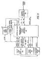
- FIG. 5is a block diagram of the electrical component circuitry for the serial-to-ethernet conversion for the ethernet connector of the present invention
- FIG. 6is a pin input and output diagram for the ethernet connector of the present invention.
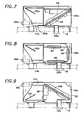
- FIG. 7is a side, partially cut-away view of an alternative embodiment of the present invention showing a horizontal circuit board in combination with an angled circuit board positioned within the interior chamber of the housing;
- FIG. 8is a side, partially cut-away view of an alternative embodiment of the present invention showing circuit boards placed on a common flexible substrate fitted with the interior chamber of the housing;
- FIG. 9is a side, partially cut-away view of an alternative embodiment of the present invention showing a vertically positioned circuit board and an angled circuit board positioned within the interior chamber of the housing;
- FIG. 10is an alternative embodiment of the present invention showing the interior chamber located beneath the connector port.
- FIG. 1shows a perspective front view of the ethernet connector 10 of the present invention.
- FIG. 2shows a front view of the connector 10 of the present invention.
- FIG. 3shows a cut-away side view of the connector 10 .
- Connector 10comprises a generally rectangular housing 12 .
- the front of the housingincludes an open cavity 14 .
- a metal Faraday shieldcovers the top, sides and back of the housing and provides for electromagnetic-radiation (EMR) protection.
- the connector 10additionally includes spring biased grounding tabs 16 that connect the Faraday shield to chassis (earth) ground by contacting the enclosure in which the connector is mounted.
- an array of leads 20for electrically interconnecting the connector 10 to a PCB 18 .
- the cavity 14 of the housing 12incorporates a planar array of parallel electrical contacts 22 to provide the necessary electrical contacts to form a connector port within the cavity 14 .
- the cavity 14is sized and dimensioned and the contacts 22 are placed within the cavity to compliment a mating plug (not shown).
- the sized cavity 14 along with the contacts 22form a standard RJ-45 connector jack.
- the jack contacts 22are spring biased for engagement with a mating plug (not shown).
- the housing 12is formed of molded plastic or other suitable material used in the art, covered by a Faraday shield having a front wall 24 , a rear wall 26 , a top wall 28 , a bottom wall 30 and sidewalls 32 and 34 .
- a Faraday shieldhaving a front wall 24 , a rear wall 26 , a top wall 28 , a bottom wall 30 and sidewalls 32 and 34 .
- the references herein of “top”, “bottom”, and “sides”are made for ease of explanation of the invention and should not be interpreted as limiting in any way. It is contemplated that the connector 10 may be oriented in a multitude of ways on a product.
- the front wall 24includes LEDs 36 and 38 .
- the LEDsprovide visual status and fault information for various functions of the serial-to-ethernet conversion, such as (but not limited to) ethernet connection speed, link present/absent, full/half duplex, ethernet activity, serial port activity, and microcontroller error conditions.
- the housing 12includes a segregated interior chamber 40 . As shown in FIG. 4 , elements 46 and 47 separate the interior chamber 40 from the cavity 14 .
- a first PCB 42is disposed within the interior chamber 40 generally horizontal and parallel relative to the bottom wall 30 .
- the first PCB 42is soldered (or otherwise electrically connected) to the contact interface 44 , which are mounted in a plastic insert.
- the completed insert assemblyslides and snaps into the main housing 12 .
- the contact interface pins 44are formed such that their ends become the wiper contacts 22 .
- the first PCB 42is electrically interconnected to the contacts 22 of the port cavity 14 .
- the contact interface 44additionally provides structural support to the first PCB 42 .
- a second PCB 50is also placed within the interior chamber 40 , positioned generally horizontal and in general parallel relation to the bottom wall 30 .
- the third PCB 50is soldered (or otherwise electrically connected) to the array of leads 54 , which are formed such that their ends become the input/output pins 20 (more specifically, these pins 20 connect power and ground, reset, serial data input and output, handshake and flow control lines, and PIO lines) that connect to the user's PCB 18 .
- the array of leads 54are mounted in a plastic insert. After the third PCB 50 is soldered (or otherwise connected) to the leads 54 , the completed insert assembly slides and snaps into the main housing 12 .
- a third PCB 48is placed within the interior chamber 40 generally vertically, and in general perpendicular relation to the other PCBs 42 and 50 .
- PCB 48is positioned adjacent the rear wall 26 and is structurally and electrically interconnected to the other PCBs 42 and 50 by the formed pins 49 and 52 .
- PCB 48 and formed pins 49 and 52thus provide the electrical connection between PCBs 42 and 50 .
- the LEDs 38have leads (not shown) that run close to the top of the enclosure 12 , and these leads also connect to holes in PCB 48 . This provides the electrical connection between the LEDs 38 and the control PCB 50 .
- the first, 42 , and second PCB 50collectively incorporate the electronic circuitry component necessary to complete a serial-to-ethernet conversion of data.
- PCB 42includes the magnetics portion of the circuitry which includes, but is not limited, to isolation transformers, common mode chokes, termination resistors, and a high voltage discharge capacitor (for ESD and voltage surges).
- PCB 48is used solely for electrical interconnection, but it could, also be used for circuitry components if required.
- PCB 50incorporates all of the electronic circuitry components necessary for the control function of the serial-to-ethernet conversion.
- the electronic components on board PCB 50include, but are not limited to, a microprocessor and an ethernet controller (combined in an ASIC for the present invention), nonvolatile memory (flash memory in the present invention), voltage regulator, voltage supervisory circuit, crystals, resistors, capacitors, and ferrite beads (surface mount beads in the present invention).
- the complete assemblyis mounted on a PCB that is a part of some device or equipment.
- Serial data and general purpose PIO dataflows from the device through the array of leads 20 and is processed by the circuitry collectively incorporated onto PCBs 42 , 48 and 50 .
- PCB 42is interconnected to the contacts 22 which mate with a plug (not shown) to effectively transmit ethernet data thereto.
- Ethernet datacan also flow from the ethernet port through wiper contacts 22 , be processed by the circuitry collectively incorporated onto PCBs 42 , 48 and 50 , and flow out as serial data and general purpose PIO data through lead pins 20 into the external device.
- the control circuitry, magnetic circuitry and LED circuitrymay be interchanged among PCBs 42 , 48 and 50 and that component may be positioned on one or both sides of each PCB's 42 , 48 and 50 .
- the controller block 56handles all of the conversion between serial and ethernet. This includes processing of the digital (serial) and analog (ethernet) signals, as well as all of the required code protocol translations.
- the controller block 56communicates with ethernet through the ethernet interface 58 , which is described below in greater detail.
- the flash memory 66stores the software that the controller block 56 uses to perform its functions.
- the supervisory circuit 68monitors the supply voltage coming in through the PCB IO pins 20 . It resets the controller block if the voltage drops too low, or if a signal from the PCB IO pins 20 requests a system reset.
- the power filters 61remove noise from the input supply voltage, and also reduce any noise that might be transmitted from the serial-to-ethernet converter to the outside world through the voltage supply lines.
- the 2.5V power supply 62supplies a second supply voltage that is required by the controller block in the present invention.
- Serial datais transmitted to and from the controller block through the PCB IO pins 20 to the external device.
- the flow control and handshake lines(connected through PCB IO pins 20 ) are standard signals used to control the serial data stream.
- the controller blockcan also communicate with the external device through the PIO lines connecting through the PCB IO pins 20 . It is understood that although the components as shown in FIG. 5 are specifically identified, it is contemplated by the present invention that any control circuitry that complete the control of function of serial-to-ethernet conversion is contemplated by the present invention.
- the outgoing ethernet signal 70 a from the controller 50passes through the isolation transformer 74 , which eliminates any DC coupling problems between ethernet devices.
- the outgoing signalspass through the common mode choke 78 , which reduces spurious emissions (radiated and conducted).
- the outgoing signalconnects to the ethernet cable through contacts 72 a of the RJ-45 jack.
- Incoming ethernet signalsenter into the jack through contacts 72 c , and pass through a common mode choke 80 which reduces spurious common mode noise that could be conducted into the device.
- the signalspass through the isolation transformer 76 , and then to the controller board 50 through pins 52 and 26 .
- the center taps 70 b and 70 c of the isolation transformers 74 and 76are used to set the appropriate DC bias levels in the transmit and receive circuitry on the controller board 50 . These center taps also connect to the controller board 50 through pins 52 and 26 .
- Four of the RJ-45 contacts 72 care not used for ethernet signals. They are terminated to ground, through matching resistors 82 c and 82 d and capacitor 84 , to reduce noise and DC transients.
- DC transients (“ESD”) on the ethernet cable that are present at the contact 72 a and 72 care reduced by discharge to ground through resistors 82 a and 82 b.
- magneticsincludes the components as described in FIG. 6 .
- FIG. 7there is shown an alternate embodiment of the present invention.
- the alternate embodiment connector as shown in FIG. 7is structurally similar to the embodiment shown in FIGS. 14 , with only the distinctions highlighted below.
- two PCBs 86 and 88are positioned therein.
- a first PCB 88is positioned generally horizontal in parallel relation to the bottom wall 30 a .
- a second PCB 86is positioned in angular relation to the PCB 88 to fit within the interior chamber 40 a .
- PCB 86 and 88collectively incorporate the electric circuitry components to complete a serial to ethernet data conversion.
- PCB 86is interconnected to a lead array 20 a .
- PCB 86includes all of the control circuitry, with components interconnected to the top side and bottom side of said PCB.
- PCB 86is interconnected to PCB 88 .
- PCB 88includes the magnetic portion of the circuitry formed on the underside of PCB 86 .
- the LEDs 38 a and 36 a(not shown) also connect to PCB 86 through leads 14 a .
- PCB 88is interconnected to contacts 22 a.
- FIG. 8there is shown an alternative embodiment of the present invention.
- the alternate embodiment connector as shown in FIG. 8is structurally similar to the embodiment as shown in FIGS. 14 , with only the distinctions highlighted below.
- a common flexible substrate(more specifically, a rigid/flexible PCB 90 , 92 , 94 , and 96 ) is formed to fit the interior chamber 40 b .
- the rigid/flexible PCB 90 , 92 , 94 , and 96collectively incorporates the electric circuitry components to complete a serial to ethernet data conversion. Electrical and magnetic components can be mounted on the rigid portions of the PCB 92 , 94 , and 96 . Electrical connections between the rigid portions 92 , 94 , and 96 are made on the flexible portions 90 .
- Rigid portion 96is electrically connected to the lead array 20 b .
- Control circuitrymay be incorporated onto rigid portion 96 and possibly 94 , with magnetic circuitry incorporated on rigid portion 92 and possibly 94 .
- the LEDsconnect to rigid portion 96 through leads 14 b .
- Rigid portion 92is electrically connected to contacts 22 . It is additionally contemplated that the control circuitry, magnetic circuitry and LED connections may be interchanged among rigid portions 92 , 94 and 96 .
- FIG. 9there is shown an alternative embodiment to the present invention.
- the alternate embodiment connector as shown in FIG. 9is structurally similar to the embodiment shown in FIGS. 1-4 , with only the distinctions highlighted below.
- the first PCB 98is positioned generally vertically in parallel relation to the rear wall 26 .
- a second PCB 100is positioned in angular relation to the PCB 98 to fit within the interior chamber 40 c .
- PCB 98 and 100collectively incorporate the electric circuitry components to complete a serial-to-ethernet data conversion.
- PCB 100is interconnected to a lead array 20 c .
- PCB 100includes all of the control circuitry with components interconnected to the top side and bottom side of said PCB.
- PCB 98is interconnected to PCB 100 .
- PCB 98includes a magnetic portion of the circuitry.
- PCB 98is interconnected to contacts 22 c .
- PCB 100is additionally interconnected to LEDs 38 c and 36 c.
- the alternate embodiment connector as shown in FIG. 10includes a connector port that is structurally similar to the embodiment shown in FIGS. 1-4 , but which does not include an interior chamber located behind the port.
- the interior chamber 102is located beneath the port cavity 14 d .
- at least one PCBis positioned therein which incorporates the electric circuitry components to complete a serial-to-ethernet data conversion. It is contemplated by the present invention that the serial-to-ethernet circuitry may be incorporated into the interior chamber 102 in a variety of ways, including those described with respect to the interior chambers of FIGS. 4 , 7 - 9 .
Landscapes
- Details Of Connecting Devices For Male And Female Coupling (AREA)
- Coupling Device And Connection With Printed Circuit (AREA)
- Manufacturing Of Electrical Connectors (AREA)
- Small-Scale Networks (AREA)
Abstract
Description
Claims (44)
Priority Applications (18)
| Application Number | Priority Date | Filing Date | Title |
|---|---|---|---|
| US10/122,867US6881096B2 (en) | 2002-04-15 | 2002-04-15 | Compact serial-to-ethernet conversion port |
| TW091112617ATW550860B (en) | 2002-04-15 | 2002-06-11 | Ethernet connector with complete integrated device server and method of assembly |
| MYPI20031043AMY127302A (en) | 2002-04-15 | 2003-03-25 | Compct serial-to-ethernet conversion port |
| DE60325346TDE60325346D1 (en) | 2002-04-15 | 2003-04-08 | COMPLETELY INTEGRATED ETHERNET CONNECTOR |
| CN200710152945ACN100594636C (en) | 2002-04-15 | 2003-04-08 | Improved device for converter and microprocessor |
| EP03718257AEP1500168B1 (en) | 2002-04-15 | 2003-04-08 | Completely integrated ethernet connector |
| CNB038139200ACN100413152C (en) | 2002-04-15 | 2003-04-08 | Fully integrated Ethernet connector |
| JP2003586971AJP2005522854A (en) | 2002-04-15 | 2003-04-08 | Fully integrated Ethernet connector |
| HK05106177.7AHK1073535B (en) | 2002-04-15 | 2003-04-08 | Completely integrated ethernet connector |
| AU2003221679AAU2003221679A1 (en) | 2002-04-15 | 2003-04-08 | Completely integrated ethernet connector |
| AT03718257TATE418168T1 (en) | 2002-04-15 | 2003-04-08 | FULLY INTEGRATED ETHERNET CONNECTOR |
| PCT/US2003/010704WO2003090317A1 (en) | 2002-04-15 | 2003-04-08 | Completely integrated ethernet connector |
| US11/060,664US7018242B2 (en) | 2002-04-15 | 2005-02-17 | Serial-to-ethernet conversion port |
| US11/084,342US7309260B2 (en) | 2002-04-15 | 2005-03-17 | Wireless communication module |
| JP2008130186AJP2008258173A (en) | 2002-04-15 | 2008-05-16 | Completely integrated ethernet (r) connector |
| JP2008130187AJP2008210816A (en) | 2002-04-15 | 2008-05-16 | Full integrated ethernet (r) connector |
| JP2008287207AJP2009026776A (en) | 2002-04-15 | 2008-11-07 | Completely integrated ethernet (r) connector |
| JP2011039013AJP5254382B2 (en) | 2002-04-15 | 2011-02-24 | Fully integrated Ethernet connector |
Applications Claiming Priority (1)
| Application Number | Priority Date | Filing Date | Title |
|---|---|---|---|
| US10/122,867US6881096B2 (en) | 2002-04-15 | 2002-04-15 | Compact serial-to-ethernet conversion port |
Related Child Applications (1)
| Application Number | Title | Priority Date | Filing Date |
|---|---|---|---|
| US11/060,664ContinuationUS7018242B2 (en) | 2002-04-15 | 2005-02-17 | Serial-to-ethernet conversion port |
Publications (2)
| Publication Number | Publication Date |
|---|---|
| US20030194908A1 US20030194908A1 (en) | 2003-10-16 |
| US6881096B2true US6881096B2 (en) | 2005-04-19 |
Family
ID=28790634
Family Applications (2)
| Application Number | Title | Priority Date | Filing Date |
|---|---|---|---|
| US10/122,867Expired - LifetimeUS6881096B2 (en) | 2002-04-15 | 2002-04-15 | Compact serial-to-ethernet conversion port |
| US11/060,664Expired - LifetimeUS7018242B2 (en) | 2002-04-15 | 2005-02-17 | Serial-to-ethernet conversion port |
Family Applications After (1)
| Application Number | Title | Priority Date | Filing Date |
|---|---|---|---|
| US11/060,664Expired - LifetimeUS7018242B2 (en) | 2002-04-15 | 2005-02-17 | Serial-to-ethernet conversion port |
Country Status (10)
| Country | Link |
|---|---|
| US (2) | US6881096B2 (en) |
| EP (1) | EP1500168B1 (en) |
| JP (5) | JP2005522854A (en) |
| CN (2) | CN100413152C (en) |
| AT (1) | ATE418168T1 (en) |
| AU (1) | AU2003221679A1 (en) |
| DE (1) | DE60325346D1 (en) |
| MY (1) | MY127302A (en) |
| TW (1) | TW550860B (en) |
| WO (1) | WO2003090317A1 (en) |
Cited By (59)
| Publication number | Priority date | Publication date | Assignee | Title |
|---|---|---|---|---|
| US20040078456A1 (en)* | 2002-10-17 | 2004-04-22 | Barry Kennedy | Serial port redirection using a management controller |
| US20050020148A1 (en)* | 2003-07-22 | 2005-01-27 | Hsi-Chih Peng | Integrated network-port socket and physical-layer device and main board incorporating the same |
| US20050186852A1 (en)* | 2004-02-24 | 2005-08-25 | Delta Electronics, Inc. | Connector module |
| US7044750B1 (en)* | 2005-07-12 | 2006-05-16 | U.D. Electronic Corp. | Network connector |
| US20060149860A1 (en)* | 2004-12-30 | 2006-07-06 | Nimrod Diamant | Virtual IDE interface and protocol for use in IDE redirection communication |
| US20060156054A1 (en)* | 2005-01-07 | 2006-07-13 | Lantronix, Inc. | Milarrs systems and methods |
| US20060168099A1 (en)* | 2004-12-30 | 2006-07-27 | Nimrod Diamant | Virtual serial port and protocol for use in serial-over-LAN communication |
| US20060190529A1 (en)* | 2003-07-01 | 2006-08-24 | T & D Corporation | Multipurpose semiconductor integrated circuit device |
| US20070015416A1 (en)* | 2005-03-23 | 2007-01-18 | Gutierrez Aurelio J | Power-enabled connector assembly and method of manufacturing |
| US20070116110A1 (en)* | 2005-11-22 | 2007-05-24 | Nimrod Diamant | Optimized video compression using hashing function |
| US7348862B1 (en)* | 2005-08-02 | 2008-03-25 | Avaya Technology Corp. | Modular connector with suppression of conducted and radiated emissions |
| US20080100467A1 (en)* | 2006-10-31 | 2008-05-01 | Downie John D | Radio frequency identification of component connections |
| US20080136716A1 (en)* | 2006-10-02 | 2008-06-12 | Petteri Annamaa | Connector antenna apparatus and methods |
| US20080207061A1 (en)* | 2007-02-22 | 2008-08-28 | Sony Corporation | Connection structure and signal transmission cable |
| US20080220657A1 (en)* | 2007-03-01 | 2008-09-11 | Thomas Rascon | Connector keep-out apparatus and methods |
| US20080233803A1 (en)* | 2007-03-01 | 2008-09-25 | Renteria Victor H | Integrated connector apparatus and methods |
| US7429178B2 (en) | 2006-09-12 | 2008-09-30 | Samtec, Inc. | Modular jack with removable contact array |
| US20080267212A1 (en)* | 2007-04-24 | 2008-10-30 | Philip John Crawley | Isolated Ethernet Physical Layer (PHY) |
| US7445507B1 (en)* | 2003-12-19 | 2008-11-04 | Nortel Networks Limited | Connector module with embedded physical layer support and method |
| US20080294800A1 (en)* | 2007-05-21 | 2008-11-27 | Nimrod Diamant | Communicating graphics data via an out of band channel |
| US20090186531A1 (en)* | 2008-01-22 | 2009-07-23 | Hon Hai Precision Ind. Co., Ltd. | Electrical connector having improved connecting module |
| US20090197430A1 (en)* | 2008-02-05 | 2009-08-06 | Delta Electronics, Inc. | Connector |
| US20090318015A1 (en)* | 2008-06-24 | 2009-12-24 | Tibbo Technology, Inc. | Connector jack with reduced host pcb footprint, assembly thereof and fabrication method of the same |
| US7699663B1 (en)* | 2009-07-29 | 2010-04-20 | Hon Hai Precision Ind. Co., Ltd. | Electrical connector with improved grounding contact |
| US7701092B1 (en) | 2003-12-19 | 2010-04-20 | Avaya, Inc. | Connector module with embedded power-over-ethernet voltage isolation and method |
| US7704098B2 (en) | 2008-07-22 | 2010-04-27 | Amphenol Corporation | Registered jack with enhanced EMI protection |
| US20100178058A1 (en)* | 2006-12-14 | 2010-07-15 | Kozischek David R | Rfid systems and methods for optical fiber network deployment and maintenance |
| US7772975B2 (en) | 2006-10-31 | 2010-08-10 | Corning Cable Systems, Llc | System for mapping connections using RFID function |
| US20100211664A1 (en)* | 2009-02-13 | 2010-08-19 | Adc Telecommunications, Inc. | Aggregation of physical layer information related to a network |
| US20100248547A1 (en)* | 2007-06-12 | 2010-09-30 | Nxp B.V. | Esd protection |
| US20110019386A1 (en)* | 2008-07-02 | 2011-01-27 | Intel Corporation | Multimode Signaling on Decoupled Input/Output and Power Channels |
| US20110141713A1 (en)* | 2009-12-11 | 2011-06-16 | Equaline Corp. | Hybrid service device and system |
| US7965186B2 (en) | 2007-03-09 | 2011-06-21 | Corning Cable Systems, Llc | Passive RFID elements having visual indicators |
| US20120026709A1 (en)* | 2010-08-02 | 2012-02-02 | Chuang Yi-Fang | Pci-e module |
| US20120040559A1 (en)* | 2010-08-16 | 2012-02-16 | Nai-Chien Chang | Connector having protection components |
| US20120052718A1 (en)* | 2010-08-26 | 2012-03-01 | Pocrass Alan L | High Frequency Local and Wide Area Networking Connector with Insertable and Removable Tranformer Component and Heat Sink |
| US8248208B2 (en) | 2008-07-15 | 2012-08-21 | Corning Cable Systems, Llc. | RFID-based active labeling system for telecommunication systems |
| US8264355B2 (en) | 2006-12-14 | 2012-09-11 | Corning Cable Systems Llc | RFID systems and methods for optical fiber network deployment and maintenance |
| US20120315799A1 (en)* | 2011-06-07 | 2012-12-13 | Tyco Electronics Corporation | Electrical connector having biasing member |
| US20130156047A1 (en)* | 2003-11-13 | 2013-06-20 | Lantronix, Inc. | Communication Protocol Converter and Method of Protocol Conversion |
| US20130286527A1 (en)* | 2012-04-26 | 2013-10-31 | Sankosha Corporation | Communication line isolator |
| US8715013B2 (en) | 2003-12-22 | 2014-05-06 | Panduit Corp. | Communications connector with improved contacts |
| US8731405B2 (en) | 2008-08-28 | 2014-05-20 | Corning Cable Systems Llc | RFID-based systems and methods for collecting telecommunications network information |
| US8727794B2 (en)* | 2011-04-26 | 2014-05-20 | Mitsubishi Electric Corporation | Electronic controller |
| US20140179163A1 (en)* | 2012-12-21 | 2014-06-26 | Hon Hai Precision Industry Co., Ltd. | Electrical connector |
| US9038141B2 (en) | 2011-12-07 | 2015-05-19 | Adc Telecommunications, Inc. | Systems and methods for using active optical cable segments |
| US9207417B2 (en) | 2012-06-25 | 2015-12-08 | Adc Telecommunications, Inc. | Physical layer management for an active optical module |
| US20160173344A1 (en)* | 2013-07-25 | 2016-06-16 | Continental Automotive Gmbh | Monitoring and diagnosis of a control device |
| US9380874B2 (en) | 2012-07-11 | 2016-07-05 | Commscope Technologies Llc | Cable including a secure physical layer management (PLM) whereby an aggregation point can be associated with a plurality of inputs |
| US9407510B2 (en) | 2013-09-04 | 2016-08-02 | Commscope Technologies Llc | Physical layer system with support for multiple active work orders and/or multiple active technicians |
| US9473361B2 (en) | 2012-07-11 | 2016-10-18 | Commscope Technologies Llc | Physical layer management at a wall plate device |
| US9525242B1 (en)* | 2015-08-24 | 2016-12-20 | Cisco Technology, Inc. | Modular connectors with electromagnetic interference suppression |
| US9544058B2 (en) | 2013-09-24 | 2017-01-10 | Commscope Technologies Llc | Pluggable active optical module with managed connectivity support and simulated memory table |
| US9563832B2 (en) | 2012-10-08 | 2017-02-07 | Corning Incorporated | Excess radio-frequency (RF) power storage and power sharing RF identification (RFID) tags, and related connection systems and methods |
| US10554792B2 (en) | 2016-09-16 | 2020-02-04 | Synq Access + Security Technology Ltd. | Multidirectional serial-ethernet data conversion apparatus |
| US11113642B2 (en) | 2012-09-27 | 2021-09-07 | Commscope Connectivity Uk Limited | Mobile application for assisting a technician in carrying out an electronic work order |
| US11424953B2 (en) | 2018-11-28 | 2022-08-23 | Kinnexa, Inc. | Modular physical layer and integrated connector module for local area networks |
| US11706034B2 (en) | 2018-03-13 | 2023-07-18 | Fobisuite Technologies Inc. | Point-of-sale system and method |
| US11817659B2 (en) | 2015-12-08 | 2023-11-14 | Panduit Corp. | RJ45 shuttered jacks and related communication systems |
Families Citing this family (88)
| Publication number | Priority date | Publication date | Assignee | Title |
|---|---|---|---|---|
| US7309260B2 (en)* | 2002-04-15 | 2007-12-18 | Lantronix, Inc. | Wireless communication module |
| US8010789B2 (en)* | 2003-11-13 | 2011-08-30 | Lantronix, Inc. | Secure data transfer using an embedded system |
| US7179131B2 (en) | 2004-02-12 | 2007-02-20 | Panduit Corp. | Methods and apparatus for reducing crosstalk in electrical connectors |
| CN1930746B (en) | 2004-03-12 | 2010-12-22 | 泛达公司 | Method and apparatus for reducing crosstalk in an electrical connector |
| US7153168B2 (en)* | 2004-04-06 | 2006-12-26 | Panduit Corp. | Electrical connector with improved crosstalk compensation |
| FR2868872A1 (en)* | 2004-04-09 | 2005-10-14 | Itt Mfg Enterprises Inc | Cable conductors connecting unit for telecommunication cable network, has transversal bar with control fingers simultaneously deforming output blades so that their front end sections are in contact with sections of input blades |
| GB0414007D0 (en)* | 2004-06-23 | 2004-07-28 | Ibm | A connector |
| WO2006000238A1 (en)* | 2004-06-24 | 2006-01-05 | Molex Incorporated | Jack connector assembly having circuitry components integrated for providing poe-functionality |
| EP1774625B1 (en) | 2004-07-13 | 2014-06-25 | Panduit Corporation | Communications connector with flexible printed circuit board |
| US7423859B1 (en)* | 2004-09-29 | 2008-09-09 | Emc Corporation | System for protecting computer equipment from lightning voltage surges |
| US7881675B1 (en) | 2005-01-07 | 2011-02-01 | Gazdzinski Robert F | Wireless connector and methods |
| EP1839374A1 (en)* | 2005-01-20 | 2007-10-03 | Telecom Design | Interface device provided with a removable module |
| JP4653525B2 (en)* | 2005-03-09 | 2011-03-16 | 株式会社東芝 | Electronics |
| US20060256556A1 (en)* | 2005-05-13 | 2006-11-16 | Huang-Chou Huang | Electrical connector |
| US20060282539A1 (en)* | 2005-06-14 | 2006-12-14 | Cisco Technology, Inc. (A California Corporation) | Method and apparatus for conveying data through an ethernet port |
| WO2007009020A2 (en)* | 2005-07-12 | 2007-01-18 | The Siemon Company | Telecommunications connector with modular element |
| ATE537586T1 (en)* | 2005-07-15 | 2011-12-15 | Panduit Corp | COMMUNICATION CONNECTOR WITH A DEVICE FOR COMPENSATING CROSSTALK |
| WO2007047708A2 (en)* | 2005-10-18 | 2007-04-26 | Pocrass Alan L | Rj female connector with integrated magnetic components |
| US8428054B2 (en)* | 2005-11-14 | 2013-04-23 | Lantronix, Inc. | Daisy chaining device servers via ethernet |
| US20070134986A1 (en)* | 2005-12-13 | 2007-06-14 | Texas Instruments Incorporated | Active enclosure for use in power over ethernet powered device |
| DE102005060798A1 (en)* | 2005-12-16 | 2007-06-21 | Yamaichi Electronics Deutschland Gmbh | Ethernet plug connector for connecting telephones has socket with electronics for electromagnetic signal transmission and power contacts for power transmission, and signal lines galvanically separated by magnets for signal transmission |
| US7101219B1 (en)* | 2005-12-20 | 2006-09-05 | Huang-Chou Huang | Adaptor with reflection fins |
| US7201604B1 (en)* | 2006-03-16 | 2007-04-10 | John Mezzalingua Associates, Inc. | Ethernet cable connector and methods of use thereof |
| US8011972B2 (en)* | 2006-02-13 | 2011-09-06 | Panduit Corp. | Connector with crosstalk compensation |
| US20070300150A1 (en)* | 2006-06-22 | 2007-12-27 | Lantronix, Inc. | Building rich web site applications with an embedded device |
| JP4915585B2 (en)* | 2006-09-21 | 2012-04-11 | パナソニック株式会社 | Modular plug |
| FR2909228A1 (en)* | 2006-11-29 | 2008-05-30 | Procedes Marechal Sepm Sa Soc | Electrical connecting device, has luminous element to visualize power supply or non-power supply of connection element based on states of electromechanical unit and to visualize connection position and connection elements under tension |
| US20080200060A1 (en)* | 2007-02-16 | 2008-08-21 | Buckmeier Brian J | Electrical Isolation Device Capable Of Limiting Magnetic Saturation Even Upon Receipt Of High Power DC Bias And Method For Making The Same |
| US7874878B2 (en) | 2007-03-20 | 2011-01-25 | Panduit Corp. | Plug/jack system having PCB with lattice network |
| US7708566B2 (en)* | 2007-10-30 | 2010-05-04 | Hon Hai Precision Ind. Co., Ltd. | Electrical connector with integrated circuit bonded thereon |
| US7682172B2 (en)* | 2007-11-29 | 2010-03-23 | Hon Hai Precision Ind. Co., Ltd. | Electrical connector assembly with ESD protection |
| TW200941857A (en)* | 2008-03-31 | 2009-10-01 | Delta Electronics Inc | Connector |
| DE102008027512B4 (en)* | 2008-06-10 | 2010-07-01 | Tyco Electronics Amp Gmbh | Electric plug |
| TWI320248B (en)* | 2008-12-02 | 2010-02-01 | Rj45 joint device with key structure to change definition of pin | |
| TWI474180B (en)* | 2008-12-10 | 2015-02-21 | Ind Tech Res Inst | System and method for detecting remote serial device |
| TWM364982U (en)* | 2008-12-22 | 2009-09-11 | nai-qian Zhang | Connector with storage function |
| TWM371983U (en)* | 2008-12-22 | 2010-01-01 | nai-qian Zhang | Structural improvement of electrical connector |
| TWI394319B (en)* | 2009-05-25 | 2013-04-21 | Hon Hai Prec Ind Co Ltd | Electrical connector |
| JP5270502B2 (en)* | 2009-09-24 | 2013-08-21 | ホシデン株式会社 | Connector and connector assembly method |
| CN102696156B (en)* | 2009-11-06 | 2016-01-20 | 莫列斯公司 | Multilayer circuit components and cable assemblies |
| US7934937B1 (en)* | 2010-01-12 | 2011-05-03 | Tyco Electronics Corporation | Connector assembly having an open volume between the assembly and a circuit board |
| CN102237586B (en)* | 2010-04-23 | 2015-11-25 | 富士康(昆山)电脑接插件有限公司 | Electric connector |
| TWI504070B (en)* | 2010-04-28 | 2015-10-11 | An improved ethernet module having a reduced host pcb footprint and dimensioned to correspond to a rear face of an rj connector jack | |
| US20110268112A1 (en)* | 2010-04-28 | 2011-11-03 | Tibbo Technology Inc. | Ethernet module having a reduced host pcb footprint and dimensioned to correspond to a rear face of an rj connector jack |
| US20120258609A1 (en)* | 2011-04-11 | 2012-10-11 | Phoenix Contact Gmbh & Co. Kg | Arrangement for controlling a system |
| DE202011005469U1 (en)* | 2011-04-20 | 2011-08-16 | Ccs Technology, Inc. | Electrical connector |
| DE102011105712B4 (en)* | 2011-06-22 | 2021-09-02 | Phoenix Contact Gmbh & Co. Kg | Coupling device for communication devices |
| US9606586B2 (en) | 2012-01-23 | 2017-03-28 | Microsoft Technology Licensing, Llc | Heat transfer device |
| US9627816B2 (en) | 2012-02-13 | 2017-04-18 | Sentinel Connector System Inc. | High speed grounded communication jack |
| US9912448B2 (en) | 2012-02-13 | 2018-03-06 | Sentinel Connector Systems, Inc. | Testing apparatus for a high speed communications jack and methods of operating the same |
| US10014990B2 (en) | 2012-02-13 | 2018-07-03 | Sentinel Connector Systems, Inc. | Testing apparatus for a high speed cross over communications jack and methods of operating the same |
| US9337592B2 (en) | 2012-02-13 | 2016-05-10 | Sentinel Connector Systems, Inc. | High speed communication jack |
| US9653847B2 (en) | 2013-01-11 | 2017-05-16 | Sentinel Connector System, Inc. | High speed communication jack |
| US8858266B2 (en)* | 2012-02-13 | 2014-10-14 | Sentinel Connector Systems, Inc. | High speed communication jack |
| US8920197B2 (en) | 2012-03-14 | 2014-12-30 | Apple Inc. | Connector receptacle with ground contact having split rear extensions |
| CN202474374U (en)* | 2012-05-14 | 2012-10-03 | 东莞维升电子制品有限公司 | Socket |
| US9011176B2 (en)* | 2012-06-09 | 2015-04-21 | Apple Inc. | ESD path for connector receptacle |
| TWI485939B (en) | 2012-10-29 | 2015-05-21 | Delta Electronics Inc | Modular connector |
| CN103915731B (en)* | 2013-01-09 | 2016-06-08 | 富士康(昆山)电脑接插件有限公司 | Electrical connection device |
| US20140242843A1 (en)* | 2013-02-22 | 2014-08-28 | Ya-Hui Huang | Signal transmission apparatus of connector |
| CA2910800C (en)* | 2013-06-03 | 2016-10-11 | Norman R. Byrne | Low voltage power receptacle |
| US9502842B2 (en)* | 2014-06-05 | 2016-11-22 | Bel Fuse (Macao Commercial Offshore) Ltd. | Network interface connector with proximity compensation |
| CN104092064B (en)* | 2014-07-10 | 2016-06-08 | 广西南宁百兰斯科技开发有限公司 | A kind of network interface converter that embeds functional module |
| CN104064912B (en)* | 2014-07-10 | 2016-06-08 | 广西南宁百兰斯科技开发有限公司 | A kind of integrated water crystal-tipped that embeds functional module |
| CN104135246A (en)* | 2014-07-24 | 2014-11-05 | 武汉鑫森华科技产业发展有限公司 | Filter circuit of RJ-45 connector |
| CA2960385C (en)* | 2014-10-01 | 2022-07-26 | Sentinel Connector Systems, Inc. | High speed communication jack |
| US9912083B2 (en) | 2015-07-21 | 2018-03-06 | Sentinel Connector Systems, Inc. | High speed plug |
| EP3375052A1 (en) | 2015-11-11 | 2018-09-19 | Bel Fuse (Macao Commercial Offshore) Limited | Modular jack connector |
| US10637196B2 (en) | 2015-11-11 | 2020-04-28 | Bel Fuse (Macao Commercial Offshore) Limited | Modular jack contact assembly having controlled capacitive coupling positioned within a jack housing |
| US9899765B2 (en) | 2016-05-04 | 2018-02-20 | Sentinel Connector Systems, Inc. | Large conductor industrial plug |
| EP3258547A1 (en)* | 2016-06-17 | 2017-12-20 | Tyco Electronics Componentes Electromecanicos Lda | Electric automotive connector with increased mounting surface |
| EP3379807A1 (en)* | 2017-03-21 | 2018-09-26 | Thomson Licensing | Device and method for forwarding connections |
| DE102017107251A1 (en)* | 2017-04-04 | 2018-10-04 | Rosenberger Hochfrequenztechnik Gmbh & Co. Kg | Electrical connector with an electrical circuit |
| USD839193S1 (en) | 2017-06-20 | 2019-01-29 | Amphenol Corporation | Cable connector |
| USD840341S1 (en) | 2017-06-20 | 2019-02-12 | Amphenol Corporation | Cable connector |
| US10186804B2 (en) | 2017-06-20 | 2019-01-22 | Amphenol Corporation | Cable connector with backshell locking |
| US10530106B2 (en) | 2018-01-31 | 2020-01-07 | Bel Fuse (Macao Commercial Offshore) Limited | Modular plug connector with multilayer PCB for very high speed applications |
| WO2019161820A1 (en)* | 2018-02-22 | 2019-08-29 | port Gesellschaft für computergestützte Automation mbH | Integrated communication unit |
| US10733136B1 (en) | 2019-03-01 | 2020-08-04 | Western Digital Technologies, Inc. | Vertical surface mount type C USB connector |
| CN111065197B (en)* | 2019-11-07 | 2024-09-03 | 晶晨半导体(深圳)有限公司 | Method for enhancing lightning protection of Ethernet by small-size PCB |
| CN111796698B (en)* | 2020-07-13 | 2024-12-06 | 旭丽电子(东莞)有限公司 | Mouse device |
| CN116093681A (en)* | 2021-11-08 | 2023-05-09 | 纽陲客股份公司 | Plug connector for data cable |
| JP7597012B2 (en)* | 2021-11-17 | 2024-12-10 | 株式会社オートネットワーク技術研究所 | Communication connector device |
| US12056565B2 (en)* | 2022-01-14 | 2024-08-06 | Zebra Technologies Corporation | Structural isolation of RFID antenna |
| EP4328746A1 (en)* | 2022-08-25 | 2024-02-28 | Siemens Schweiz AG | Serial interface for containers |
| USD1057667S1 (en) | 2022-11-07 | 2025-01-14 | Thales Dis Cpl Usa, Inc. | Multi-ethernet port locking cover |
| JP2024081178A (en)* | 2022-12-06 | 2024-06-18 | 株式会社オートネットワーク技術研究所 | Connector device |
| EP4485711A1 (en)* | 2023-06-27 | 2025-01-01 | TE Connectivity Nederland B.V. | Hybrid spe connector unit |
Citations (17)
| Publication number | Priority date | Publication date | Assignee | Title |
|---|---|---|---|---|
| US4603320A (en) | 1983-04-13 | 1986-07-29 | Anico Research, Ltd. Inc. | Connector interface |
| US4789847A (en) | 1986-03-05 | 1988-12-06 | Murata Manufacturing Co., Ltd. | Filter connector |
| US4972470A (en) | 1987-08-06 | 1990-11-20 | Steven Farago | Programmable connector |
| US4978317A (en) | 1989-03-27 | 1990-12-18 | Alan Pocrass | Connector with visual indicator |
| US5015204A (en) | 1988-12-12 | 1991-05-14 | Murata Manufacturing Co., Ltd. | Modular jack |
| US5069641A (en) | 1990-02-03 | 1991-12-03 | Murata Manufacturing Co., Ltd. | Modular jack |
| US5139442A (en) | 1990-12-03 | 1992-08-18 | Murata Manufacturing Co., Ltd. | Modular jack |
| US5282759A (en) | 1991-09-13 | 1994-02-01 | Murata Manufacturing Co., Ltd. | Modular jack |
| US5587884A (en)* | 1995-02-06 | 1996-12-24 | The Whitaker Corporation | Electrical connector jack with encapsulated signal conditioning components |
| US5647765A (en) | 1995-09-12 | 1997-07-15 | Regal Electronics, Inc. | Shielded connector with conductive gasket interface |
| US5647767A (en)* | 1995-02-06 | 1997-07-15 | The Whitaker Corporation | Electrical connector jack assembly for signal transmission |
| US6062908A (en) | 1997-01-27 | 2000-05-16 | Pulse Engineering, Inc. | High density connector modules having integral filtering components within repairable, replaceable submodules |
| US6203334B1 (en)* | 1999-06-23 | 2001-03-20 | Avaya Technology Corp. | Modular jack receptacle including a removable interface |
| US6350152B1 (en)* | 2000-08-23 | 2002-02-26 | Berg Technology Inc. | Stacked electrical connector for use with a filter insert |
| US6381283B1 (en) | 1998-10-07 | 2002-04-30 | Controlnet, Inc. | Integrated socket with chip carrier |
| US20020119702A1 (en)* | 2000-08-22 | 2002-08-29 | John Chen | EMI suppression technique for RJ connectors with integrated magnetics |
| US6478611B1 (en)* | 2001-11-08 | 2002-11-12 | Hon Hai Precision Ind. Co., Ltd. | Electrical connector with visual indicator |
Family Cites Families (22)
| Publication number | Priority date | Publication date | Assignee | Title |
|---|---|---|---|---|
| JPS5392490A (en)* | 1977-01-21 | 1978-08-14 | Bunker Ramo | Connecting terminal module and method of producing same |
| JPH0634261Y2 (en)* | 1989-10-11 | 1994-09-07 | シール工業株式会社 | Deaeration device for bag mouth sealing machine |
| JPH0376234U (en)* | 1989-11-20 | 1991-07-31 | ||
| JP2504979Y2 (en)* | 1990-02-03 | 1996-07-24 | 株式会社村田製作所 | Modular jack |
| JPH0447688A (en)* | 1990-06-13 | 1992-02-17 | Konica Corp | Mounting method for multistage board |
| JPH04209481A (en)* | 1990-12-07 | 1992-07-30 | Murata Mfg Co Ltd | Modular jack |
| US5415556A (en)* | 1993-12-06 | 1995-05-16 | Xerox Corporation | Hybird packaging of integrated I/O interface device and connector module |
| DE4403730A1 (en)* | 1994-02-07 | 1995-08-10 | Daetwyler System Und Netzwerk | Device for connecting data network cabling |
| DE69524896T2 (en)* | 1994-03-25 | 2002-11-14 | Nec Corp., Tokio/Tokyo | Playback of video images at increased speed |
| JPH08180915A (en)* | 1994-12-26 | 1996-07-12 | Hosiden Corp | Modulator jack |
| US5736910A (en)* | 1995-11-22 | 1998-04-07 | Stewart Connector Systems, Inc. | Modular jack connector with a flexible laminate capacitor mounted on a circuit board |
| JPH09204963A (en)* | 1996-01-25 | 1997-08-05 | Mitsubishi Electric Corp | IC card |
| AU3655199A (en)* | 1998-04-21 | 1999-11-08 | Bel-Fuse, Inc. | Female connectors and methods of making same |
| US6697892B1 (en)* | 1999-07-08 | 2004-02-24 | Intel Corporation | Port expansion system |
| JP2001067293A (en)* | 1999-08-31 | 2001-03-16 | Hitachi Denshi Ltd | TCP / IP protocol converter |
| US6390851B1 (en)* | 1999-10-16 | 2002-05-21 | Berg Technology, Inc. | Electrical connector with internal shield |
| JP3449542B2 (en)* | 1999-12-22 | 2003-09-22 | 日本電気株式会社 | MAC frame transfer method and frame transfer system |
| JP2001267022A (en)* | 2000-03-15 | 2001-09-28 | Denso Corp | Electronic controller |
| US6364535B1 (en)* | 2000-08-10 | 2002-04-02 | Adc | Upgradeable media wall converter and housing |
| US20020042857A1 (en)* | 2000-10-05 | 2002-04-11 | Jones Nicolas D.L. | Industrial multi-port data connector system |
| CN2454931Y (en)* | 2000-11-08 | 2001-10-17 | 富士康(昆山)电脑接插件有限公司 | Electric connector |
| JP3783558B2 (en)* | 2000-11-30 | 2006-06-07 | 松下電工株式会社 | Modular connector |
- 2002
- 2002-04-15USUS10/122,867patent/US6881096B2/ennot_activeExpired - Lifetime
- 2002-06-11TWTW091112617Apatent/TW550860B/ennot_activeIP Right Cessation
- 2003
- 2003-03-25MYMYPI20031043Apatent/MY127302A/enunknown
- 2003-04-08CNCNB038139200Apatent/CN100413152C/ennot_activeExpired - Lifetime
- 2003-04-08EPEP03718257Apatent/EP1500168B1/ennot_activeExpired - Lifetime
- 2003-04-08DEDE60325346Tpatent/DE60325346D1/ennot_activeExpired - Lifetime
- 2003-04-08CNCN200710152945Apatent/CN100594636C/ennot_activeExpired - Lifetime
- 2003-04-08WOPCT/US2003/010704patent/WO2003090317A1/enactiveApplication Filing
- 2003-04-08ATAT03718257Tpatent/ATE418168T1/ennot_activeIP Right Cessation
- 2003-04-08AUAU2003221679Apatent/AU2003221679A1/ennot_activeAbandoned
- 2003-04-08JPJP2003586971Apatent/JP2005522854A/ennot_activeWithdrawn
- 2005
- 2005-02-17USUS11/060,664patent/US7018242B2/ennot_activeExpired - Lifetime
- 2008
- 2008-05-16JPJP2008130187Apatent/JP2008210816A/enactivePending
- 2008-05-16JPJP2008130186Apatent/JP2008258173A/enactivePending
- 2008-11-07JPJP2008287207Apatent/JP2009026776A/enactivePending
- 2011
- 2011-02-24JPJP2011039013Apatent/JP5254382B2/ennot_activeExpired - Lifetime
Patent Citations (17)
| Publication number | Priority date | Publication date | Assignee | Title |
|---|---|---|---|---|
| US4603320A (en) | 1983-04-13 | 1986-07-29 | Anico Research, Ltd. Inc. | Connector interface |
| US4789847A (en) | 1986-03-05 | 1988-12-06 | Murata Manufacturing Co., Ltd. | Filter connector |
| US4972470A (en) | 1987-08-06 | 1990-11-20 | Steven Farago | Programmable connector |
| US5015204A (en) | 1988-12-12 | 1991-05-14 | Murata Manufacturing Co., Ltd. | Modular jack |
| US4978317A (en) | 1989-03-27 | 1990-12-18 | Alan Pocrass | Connector with visual indicator |
| US5069641A (en) | 1990-02-03 | 1991-12-03 | Murata Manufacturing Co., Ltd. | Modular jack |
| US5139442A (en) | 1990-12-03 | 1992-08-18 | Murata Manufacturing Co., Ltd. | Modular jack |
| US5282759A (en) | 1991-09-13 | 1994-02-01 | Murata Manufacturing Co., Ltd. | Modular jack |
| US5587884A (en)* | 1995-02-06 | 1996-12-24 | The Whitaker Corporation | Electrical connector jack with encapsulated signal conditioning components |
| US5647767A (en)* | 1995-02-06 | 1997-07-15 | The Whitaker Corporation | Electrical connector jack assembly for signal transmission |
| US5647765A (en) | 1995-09-12 | 1997-07-15 | Regal Electronics, Inc. | Shielded connector with conductive gasket interface |
| US6062908A (en) | 1997-01-27 | 2000-05-16 | Pulse Engineering, Inc. | High density connector modules having integral filtering components within repairable, replaceable submodules |
| US6381283B1 (en) | 1998-10-07 | 2002-04-30 | Controlnet, Inc. | Integrated socket with chip carrier |
| US6203334B1 (en)* | 1999-06-23 | 2001-03-20 | Avaya Technology Corp. | Modular jack receptacle including a removable interface |
| US20020119702A1 (en)* | 2000-08-22 | 2002-08-29 | John Chen | EMI suppression technique for RJ connectors with integrated magnetics |
| US6350152B1 (en)* | 2000-08-23 | 2002-02-26 | Berg Technology Inc. | Stacked electrical connector for use with a filter insert |
| US6478611B1 (en)* | 2001-11-08 | 2002-11-12 | Hon Hai Precision Ind. Co., Ltd. | Electrical connector with visual indicator |
Non-Patent Citations (2)
| Title |
|---|
| (Internet Literature) Amphenol Canada Corp., "RJmag," Feb., 2000, 6 pgs., Canada. |
| (Internet Literature) Tyco Electronics, "Amp Gigabit Ethernet Multimode SFP MT-RJ Transceivers," Catalog 1308513, Oct. 10, 2000, pp. 1-11. |
Cited By (117)
| Publication number | Priority date | Publication date | Assignee | Title |
|---|---|---|---|---|
| US20040078456A1 (en)* | 2002-10-17 | 2004-04-22 | Barry Kennedy | Serial port redirection using a management controller |
| US7225247B2 (en)* | 2002-10-17 | 2007-05-29 | Intel Corporation | Serial port redirection using a management controller |
| US7822934B2 (en)* | 2003-07-01 | 2010-10-26 | T&D Corporation | Multipurpose semiconductor integrated circuit device |
| US20060190529A1 (en)* | 2003-07-01 | 2006-08-24 | T & D Corporation | Multipurpose semiconductor integrated circuit device |
| US20050020148A1 (en)* | 2003-07-22 | 2005-01-27 | Hsi-Chih Peng | Integrated network-port socket and physical-layer device and main board incorporating the same |
| US20130156047A1 (en)* | 2003-11-13 | 2013-06-20 | Lantronix, Inc. | Communication Protocol Converter and Method of Protocol Conversion |
| US7445507B1 (en)* | 2003-12-19 | 2008-11-04 | Nortel Networks Limited | Connector module with embedded physical layer support and method |
| US7701092B1 (en) | 2003-12-19 | 2010-04-20 | Avaya, Inc. | Connector module with embedded power-over-ethernet voltage isolation and method |
| US8715013B2 (en) | 2003-12-22 | 2014-05-06 | Panduit Corp. | Communications connector with improved contacts |
| US9287635B2 (en) | 2003-12-22 | 2016-03-15 | Panduit Corp. | Communications connector with improved contacts |
| US9011181B2 (en) | 2003-12-22 | 2015-04-21 | Panduit Corp. | Communications connector with improved contacts |
| US20050186852A1 (en)* | 2004-02-24 | 2005-08-25 | Delta Electronics, Inc. | Connector module |
| US20110196970A1 (en)* | 2004-12-30 | 2011-08-11 | Nimrod Diamant | Redirection communication |
| US20060149860A1 (en)* | 2004-12-30 | 2006-07-06 | Nimrod Diamant | Virtual IDE interface and protocol for use in IDE redirection communication |
| US7949798B2 (en) | 2004-12-30 | 2011-05-24 | Intel Corporation | Virtual IDE interface and protocol for use in IDE redirection communication |
| US9569372B2 (en) | 2004-12-30 | 2017-02-14 | Intel Corporation | Redirection communication |
| US8706839B2 (en) | 2004-12-30 | 2014-04-22 | Intel Corporation | Virtual serial port and protocol for use in serial-over-LAN communication |
| US8150973B2 (en) | 2004-12-30 | 2012-04-03 | Intel Corporation | Virtual serial port and protocol for use in serial-over-LAN communication |
| US20060168099A1 (en)* | 2004-12-30 | 2006-07-27 | Nimrod Diamant | Virtual serial port and protocol for use in serial-over-LAN communication |
| US8626969B2 (en) | 2004-12-30 | 2014-01-07 | Intel Corporation | Redirection communication |
| US20090254646A1 (en)* | 2005-01-07 | 2009-10-08 | Lantronix, Inc. | Milarrs systems and methods |
| US20120016925A1 (en)* | 2005-01-07 | 2012-01-19 | Lantronix, Inc. | Milarrs systems and methods |
| US8504740B2 (en) | 2005-01-07 | 2013-08-06 | Lantronix, Inc. | MILARRS systems and methods |
| US20060156054A1 (en)* | 2005-01-07 | 2006-07-13 | Lantronix, Inc. | Milarrs systems and methods |
| US8219661B2 (en)* | 2005-01-07 | 2012-07-10 | Lantronix, Inc. | MILARRS systems and methods |
| US7698405B2 (en)* | 2005-01-07 | 2010-04-13 | Lantronix, Inc. | MILARRS systems and methods |
| US7524206B2 (en) | 2005-03-23 | 2009-04-28 | Pulse Engineering, Inc. | Power-enabled connector assembly with heat dissipation apparatus and method of manufacturing |
| US20070015416A1 (en)* | 2005-03-23 | 2007-01-18 | Gutierrez Aurelio J | Power-enabled connector assembly and method of manufacturing |
| US7044750B1 (en)* | 2005-07-12 | 2006-05-16 | U.D. Electronic Corp. | Network connector |
| US7348862B1 (en)* | 2005-08-02 | 2008-03-25 | Avaya Technology Corp. | Modular connector with suppression of conducted and radiated emissions |
| US7986844B2 (en) | 2005-11-22 | 2011-07-26 | Intel Corporation | Optimized video compression using hashing function |
| US20070116110A1 (en)* | 2005-11-22 | 2007-05-24 | Nimrod Diamant | Optimized video compression using hashing function |
| US7429178B2 (en) | 2006-09-12 | 2008-09-30 | Samtec, Inc. | Modular jack with removable contact array |
| US20080136716A1 (en)* | 2006-10-02 | 2008-06-12 | Petteri Annamaa | Connector antenna apparatus and methods |
| US7724204B2 (en) | 2006-10-02 | 2010-05-25 | Pulse Engineering, Inc. | Connector antenna apparatus and methods |
| US7772975B2 (en) | 2006-10-31 | 2010-08-10 | Corning Cable Systems, Llc | System for mapping connections using RFID function |
| US7782202B2 (en) | 2006-10-31 | 2010-08-24 | Corning Cable Systems, Llc | Radio frequency identification of component connections |
| US20080100467A1 (en)* | 2006-10-31 | 2008-05-01 | Downie John D | Radio frequency identification of component connections |
| US20100178058A1 (en)* | 2006-12-14 | 2010-07-15 | Kozischek David R | Rfid systems and methods for optical fiber network deployment and maintenance |
| US7760094B1 (en) | 2006-12-14 | 2010-07-20 | Corning Cable Systems Llc | RFID systems and methods for optical fiber network deployment and maintenance |
| US8264355B2 (en) | 2006-12-14 | 2012-09-11 | Corning Cable Systems Llc | RFID systems and methods for optical fiber network deployment and maintenance |
| US20080207061A1 (en)* | 2007-02-22 | 2008-08-28 | Sony Corporation | Connection structure and signal transmission cable |
| US7559803B2 (en)* | 2007-02-22 | 2009-07-14 | Sony Corporation | Connection structure and signal transmission cable |
| US20080220657A1 (en)* | 2007-03-01 | 2008-09-11 | Thomas Rascon | Connector keep-out apparatus and methods |
| US7708602B2 (en) | 2007-03-01 | 2010-05-04 | Pulse Engineering, Inc. | Connector keep-out apparatus and methods |
| US20120196456A1 (en)* | 2007-03-01 | 2012-08-02 | Renteria Victor H | Integrated connector apparatus and methods |
| US20080233803A1 (en)* | 2007-03-01 | 2008-09-25 | Renteria Victor H | Integrated connector apparatus and methods |
| US8147278B2 (en)* | 2007-03-01 | 2012-04-03 | Pulse Electronics, Inc. | Integrated connector apparatus and methods |
| US8764493B2 (en)* | 2007-03-01 | 2014-07-01 | Pulse Electronics, Inc. | Integrated connector apparatus and methods |
| US7965186B2 (en) | 2007-03-09 | 2011-06-21 | Corning Cable Systems, Llc | Passive RFID elements having visual indicators |
| US20080267212A1 (en)* | 2007-04-24 | 2008-10-30 | Philip John Crawley | Isolated Ethernet Physical Layer (PHY) |
| US9185834B2 (en)* | 2007-04-24 | 2015-11-10 | Akros Silicon, Inc. | Isolated ethernet physical layer (PHY) |
| US20080294800A1 (en)* | 2007-05-21 | 2008-11-27 | Nimrod Diamant | Communicating graphics data via an out of band channel |
| US7721013B2 (en) | 2007-05-21 | 2010-05-18 | Intel Corporation | Communicating graphics data via an out of band channel |
| US8062068B2 (en)* | 2007-06-12 | 2011-11-22 | Nxp B.V. | ESD protection |
| US20100248547A1 (en)* | 2007-06-12 | 2010-09-30 | Nxp B.V. | Esd protection |
| US20090186531A1 (en)* | 2008-01-22 | 2009-07-23 | Hon Hai Precision Ind. Co., Ltd. | Electrical connector having improved connecting module |
| US7837511B2 (en)* | 2008-01-22 | 2010-11-23 | Hon Hai Precision Ind. Co., Ltd. | Electrical connector having improved connecting module |
| US20090197430A1 (en)* | 2008-02-05 | 2009-08-06 | Delta Electronics, Inc. | Connector |
| US20090318015A1 (en)* | 2008-06-24 | 2009-12-24 | Tibbo Technology, Inc. | Connector jack with reduced host pcb footprint, assembly thereof and fabrication method of the same |
| US7789713B2 (en) | 2008-06-24 | 2010-09-07 | Tibbo Technology, Inc. | Connector jack with reduced host PCB footprint, assembly thereof and fabrication method of the same |
| US7989946B2 (en)* | 2008-07-02 | 2011-08-02 | Intel Corporation | Multimode signaling on decoupled input/output and power channels |
| US20110019386A1 (en)* | 2008-07-02 | 2011-01-27 | Intel Corporation | Multimode Signaling on Decoupled Input/Output and Power Channels |
| US8450201B2 (en) | 2008-07-02 | 2013-05-28 | Intel Corporation | Multimode signaling on decoupled input/output and power channels |
| US8248208B2 (en) | 2008-07-15 | 2012-08-21 | Corning Cable Systems, Llc. | RFID-based active labeling system for telecommunication systems |
| US7704098B2 (en) | 2008-07-22 | 2010-04-27 | Amphenol Corporation | Registered jack with enhanced EMI protection |
| US9058529B2 (en) | 2008-08-28 | 2015-06-16 | Corning Optical Communications LLC | RFID-based systems and methods for collecting telecommunications network information |
| US8731405B2 (en) | 2008-08-28 | 2014-05-20 | Corning Cable Systems Llc | RFID-based systems and methods for collecting telecommunications network information |
| US20100211697A1 (en)* | 2009-02-13 | 2010-08-19 | Adc Telecommunications, Inc. | Managed connectivity devices, systems, and methods |
| US9742696B2 (en) | 2009-02-13 | 2017-08-22 | Commscope Technologies Llc | Network management systems for use with physical layer information |
| US9674115B2 (en) | 2009-02-13 | 2017-06-06 | Commscope Technologies Llc | Aggregation of physical layer information related to a network |
| US9667566B2 (en) | 2009-02-13 | 2017-05-30 | Commscope Technologies Llc | Inter-networking devices for use with physical layer information |
| US9491119B2 (en) | 2009-02-13 | 2016-11-08 | Commscope Technologies Llc | Network management systems for use with physical layer information |
| US20100211664A1 (en)* | 2009-02-13 | 2010-08-19 | Adc Telecommunications, Inc. | Aggregation of physical layer information related to a network |
| US20100215049A1 (en)* | 2009-02-13 | 2010-08-26 | Adc Telecommunications, Inc. | Inter-networking devices for use with physical layer information |
| US10129179B2 (en) | 2009-02-13 | 2018-11-13 | Commscope Technologies Llc | Managed connectivity devices, systems, and methods |
| US20100211665A1 (en)* | 2009-02-13 | 2010-08-19 | Adc Telecommunications, Inc. | Network management systems for use with physical layer information |
| US10554582B2 (en) | 2009-02-13 | 2020-02-04 | CommScope Technolgies LLC | System including management system to determine configuration for inter-networking device based on physical layer information of a network |
| US8982715B2 (en) | 2009-02-13 | 2015-03-17 | Adc Telecommunications, Inc. | Inter-networking devices for use with physical layer information |
| US7699663B1 (en)* | 2009-07-29 | 2010-04-20 | Hon Hai Precision Ind. Co., Ltd. | Electrical connector with improved grounding contact |
| US20110141713A1 (en)* | 2009-12-11 | 2011-06-16 | Equaline Corp. | Hybrid service device and system |
| US8456863B2 (en)* | 2009-12-11 | 2013-06-04 | Equaline Corp. | Hybrid service device and system |
| TWI416981B (en)* | 2009-12-11 | 2013-11-21 | Equaline Corp | Hybrid service device and system |
| US8369101B2 (en)* | 2010-08-02 | 2013-02-05 | Chuang Yi-Fang | PCI-E module |
| US20120026709A1 (en)* | 2010-08-02 | 2012-02-02 | Chuang Yi-Fang | Pci-e module |
| US20120040559A1 (en)* | 2010-08-16 | 2012-02-16 | Nai-Chien Chang | Connector having protection components |
| US8152564B2 (en)* | 2010-08-16 | 2012-04-10 | Nai-Chien Chang | Connector having protection components |
| US20120052718A1 (en)* | 2010-08-26 | 2012-03-01 | Pocrass Alan L | High Frequency Local and Wide Area Networking Connector with Insertable and Removable Tranformer Component and Heat Sink |
| US8357010B2 (en)* | 2010-08-26 | 2013-01-22 | Pocrass Alan L | High frequency local and wide area networking connector with insertable and removable tranformer component and heat sink |
| US8727794B2 (en)* | 2011-04-26 | 2014-05-20 | Mitsubishi Electric Corporation | Electronic controller |
| US8439710B2 (en)* | 2011-06-07 | 2013-05-14 | Tyco Electronics Corporation | Electrical connector having biasing member |
| US20120315799A1 (en)* | 2011-06-07 | 2012-12-13 | Tyco Electronics Corporation | Electrical connector having biasing member |
| USRE47365E1 (en) | 2011-12-07 | 2019-04-23 | Commscope Technologies Llc | Systems and methods for using active optical cable segments |
| US9038141B2 (en) | 2011-12-07 | 2015-05-19 | Adc Telecommunications, Inc. | Systems and methods for using active optical cable segments |
| US20130286527A1 (en)* | 2012-04-26 | 2013-10-31 | Sankosha Corporation | Communication line isolator |
| US9153955B2 (en)* | 2012-04-26 | 2015-10-06 | Sankosha Corporation | Communication line isolator |
| US9207417B2 (en) | 2012-06-25 | 2015-12-08 | Adc Telecommunications, Inc. | Physical layer management for an active optical module |
| US9602897B2 (en) | 2012-06-25 | 2017-03-21 | Commscope Technologies Llc | Physical layer management for an active optical module |
| US9742704B2 (en) | 2012-07-11 | 2017-08-22 | Commscope Technologies Llc | Physical layer management at a wall plate device |
| US9473361B2 (en) | 2012-07-11 | 2016-10-18 | Commscope Technologies Llc | Physical layer management at a wall plate device |
| US9380874B2 (en) | 2012-07-11 | 2016-07-05 | Commscope Technologies Llc | Cable including a secure physical layer management (PLM) whereby an aggregation point can be associated with a plurality of inputs |
| US11113642B2 (en) | 2012-09-27 | 2021-09-07 | Commscope Connectivity Uk Limited | Mobile application for assisting a technician in carrying out an electronic work order |
| US9563832B2 (en) | 2012-10-08 | 2017-02-07 | Corning Incorporated | Excess radio-frequency (RF) power storage and power sharing RF identification (RFID) tags, and related connection systems and methods |
| US20140179163A1 (en)* | 2012-12-21 | 2014-06-26 | Hon Hai Precision Industry Co., Ltd. | Electrical connector |
| US9077120B2 (en)* | 2012-12-21 | 2015-07-07 | Hon Hai Precision Industry Co., Ltd. | Electrical connector |
| US10142189B2 (en)* | 2013-07-25 | 2018-11-27 | Continental Automotive Gmbh | Monitoring and diagnosis of a control device |
| US20160173344A1 (en)* | 2013-07-25 | 2016-06-16 | Continental Automotive Gmbh | Monitoring and diagnosis of a control device |
| US9905089B2 (en) | 2013-09-04 | 2018-02-27 | Commscope Technologies Llc | Physical layer system with support for multiple active work orders and/or multiple active technicians |
| US9407510B2 (en) | 2013-09-04 | 2016-08-02 | Commscope Technologies Llc | Physical layer system with support for multiple active work orders and/or multiple active technicians |
| US10700778B2 (en) | 2013-09-24 | 2020-06-30 | Commscope Technologies Llc | Pluggable active optical module with managed connectivity support and simulated memory table |
| US10205519B2 (en) | 2013-09-24 | 2019-02-12 | Commscope Technologies Llc | Pluggable active optical module with managed connectivity support and simulated memory table |
| US9544058B2 (en) | 2013-09-24 | 2017-01-10 | Commscope Technologies Llc | Pluggable active optical module with managed connectivity support and simulated memory table |
| US9525242B1 (en)* | 2015-08-24 | 2016-12-20 | Cisco Technology, Inc. | Modular connectors with electromagnetic interference suppression |
| US11817659B2 (en) | 2015-12-08 | 2023-11-14 | Panduit Corp. | RJ45 shuttered jacks and related communication systems |
| US10554792B2 (en) | 2016-09-16 | 2020-02-04 | Synq Access + Security Technology Ltd. | Multidirectional serial-ethernet data conversion apparatus |
| US11706034B2 (en) | 2018-03-13 | 2023-07-18 | Fobisuite Technologies Inc. | Point-of-sale system and method |
| US11424953B2 (en) | 2018-11-28 | 2022-08-23 | Kinnexa, Inc. | Modular physical layer and integrated connector module for local area networks |
Also Published As
| Publication number | Publication date |
|---|---|
| CN100413152C (en) | 2008-08-20 |
| EP1500168B1 (en) | 2008-12-17 |
| JP2009026776A (en) | 2009-02-05 |
| JP2005522854A (en) | 2005-07-28 |
| EP1500168A4 (en) | 2006-06-21 |
| MY127302A (en) | 2006-11-30 |
| US20030194908A1 (en) | 2003-10-16 |
| AU2003221679A1 (en) | 2003-11-03 |
| CN101188334A (en) | 2008-05-28 |
| EP1500168A1 (en) | 2005-01-26 |
| US7018242B2 (en) | 2006-03-28 |
| CN1663078A (en) | 2005-08-31 |
| JP2008210816A (en) | 2008-09-11 |
| ATE418168T1 (en) | 2009-01-15 |
| WO2003090317A1 (en) | 2003-10-30 |
| JP2011129534A (en) | 2011-06-30 |
| DE60325346D1 (en) | 2009-01-29 |
| HK1073535A1 (en) | 2005-10-07 |
| CN100594636C (en) | 2010-03-17 |
| US20050136731A1 (en) | 2005-06-23 |
| TW550860B (en) | 2003-09-01 |
| JP5254382B2 (en) | 2013-08-07 |
| JP2008258173A (en) | 2008-10-23 |
Similar Documents
| Publication | Publication Date | Title |
|---|---|---|
| US6881096B2 (en) | Compact serial-to-ethernet conversion port | |
| EP1703698B1 (en) | Wireless communication port | |
| US8924518B2 (en) | Communication protocol converter and method of protocol conversion | |
| US20060175905A1 (en) | Integrated Connector Unit | |
| US8411451B2 (en) | Power line communication apparatus | |
| EP0623977A1 (en) | Cable assembly for multiple electronic components | |
| CA2290835A1 (en) | Multi-deck electric outlet assembly | |
| JP2004087486A (en) | Pluggable electrical transceiver module with high density form factor | |
| US20250007193A1 (en) | Hybrid SPE Connector Unit | |
| HK1073535B (en) | Completely integrated ethernet connector | |
| GB2312566A (en) | An adapter | |
| WO2014084783A1 (en) | Modular connector | |
| US10819053B1 (en) | Stacked multiport 10GBase-T midspan PSE for IEEE standard 802.3bt standard | |
| US20240072497A1 (en) | Perpendicularly mounted network jack with secure connector and magnetics | |
| JP2003198488A (en) | Digital filter adaptor | |
| WO2022174272A1 (en) | A modular electrical connecting apparatus |
Legal Events
| Date | Code | Title | Description |
|---|---|---|---|
| AS | Assignment | Owner name:LANTRONIX, INC., CALIFORNIA Free format text:ASSIGNMENT OF ASSIGNORS INTEREST;ASSIGNORS:BROWN, CURTIS D.;BROWER, CHARLES J.;REEL/FRAME:013037/0306;SIGNING DATES FROM 20020611 TO 20020612 | |
| STCF | Information on status: patent grant | Free format text:PATENTED CASE | |
| AS | Assignment | Owner name:SILICON VALLEY BANK,CALIFORNIA Free format text:SECURITY AGREEMENT;ASSIGNOR:LANTRONIX, INC.;REEL/FRAME:017663/0392 Effective date:20060517 Owner name:SILICON VALLEY BANK, CALIFORNIA Free format text:SECURITY AGREEMENT;ASSIGNOR:LANTRONIX, INC.;REEL/FRAME:017663/0392 Effective date:20060517 | |
| FPAY | Fee payment | Year of fee payment:4 | |
| FPAY | Fee payment | Year of fee payment:8 | |
| FPAY | Fee payment | Year of fee payment:12 | |
| AS | Assignment | Owner name:TRANSITION NEWTORKS, INC., CALIFORNIA Free format text:RELEASE BY SECURED PARTY;ASSIGNOR:SVB INNOVATION CREDIT FUND VIII, L.P.;REEL/FRAME:071290/0001 Effective date:20220120 Owner name:LANTRONIX CANADA, ULC, CALIFORNIA Free format text:RELEASE BY SECURED PARTY;ASSIGNOR:SVB INNOVATION CREDIT FUND VIII, L.P.;REEL/FRAME:071290/0001 Effective date:20220120 Owner name:LANTRONIX TECHNOLOGIES CANADA (TAIWAN) LTD., CALIFORNIA Free format text:RELEASE BY SECURED PARTY;ASSIGNOR:SVB INNOVATION CREDIT FUND VIII, L.P.;REEL/FRAME:071290/0001 Effective date:20220120 Owner name:LANTRONIX HOLDING COMPANY, CALIFORNIA Free format text:RELEASE BY SECURED PARTY;ASSIGNOR:SVB INNOVATION CREDIT FUND VIII, L.P.;REEL/FRAME:071290/0001 Effective date:20220120 Owner name:LANTRONIX, INC., CALIFORNIA Free format text:RELEASE BY SECURED PARTY;ASSIGNOR:SVB INNOVATION CREDIT FUND VIII, L.P.;REEL/FRAME:071290/0001 Effective date:20220120 Owner name:SILICON VALLEY BANK, CALIFORNIA Free format text:SECURITY INTEREST;ASSIGNORS:LANTRONIX, INC.;LANTRONIX HOLDING COMPANY;LANTRONIX TECHNOLOGIES CANADA (TAIWAN) LTD.;AND OTHERS;REEL/FRAME:071290/0044 Effective date:20221012 |