US6881029B2 - Casing, a compressor, a turbine, and a combustion turbine engine including such a casing - Google Patents
Casing, a compressor, a turbine, and a combustion turbine engine including such a casingDownload PDFInfo
- Publication number
- US6881029B2 US6881029B2US10/681,265US68126503AUS6881029B2US 6881029 B2US6881029 B2US 6881029B2US 68126503 AUS68126503 AUS 68126503AUS 6881029 B2US6881029 B2US 6881029B2
- Authority
- US
- United States
- Prior art keywords
- cells
- blades
- casing
- plate
- series
- Prior art date
- Legal status (The legal status is an assumption and is not a legal conclusion. Google has not performed a legal analysis and makes no representation as to the accuracy of the status listed.)
- Expired - Lifetime, expires
Links
- 238000002485combustion reactionMethods0.000titleclaimsdescription4
- 239000000463materialSubstances0.000claimsabstractdescription19
- 241000264877Hippospongia communisSpecies0.000claimsdescription8
- 239000011324beadSubstances0.000claimsdescription8
- 229910052751metalInorganic materials0.000claimsdescription8
- 239000002184metalSubstances0.000claimsdescription8
- 229920005989resinPolymers0.000claimsdescription6
- 239000011347resinSubstances0.000claimsdescription6
- 238000011144upstream manufacturingMethods0.000claimsdescription6
- 230000001413cellular effectEffects0.000claimsdescription5
- 239000011521glassSubstances0.000claimsdescription5
- 229920002050silicone resinPolymers0.000claimsdescription4
- 230000001154acute effectEffects0.000claimsdescription3
- 229920001296polysiloxanePolymers0.000claimsdescription3
- 210000004027cellAnatomy0.000description54
- 229910000838Al alloyInorganic materials0.000description2
- 230000000593degrading effectEffects0.000description2
- 238000009826distributionMethods0.000description2
- 229910001200FerrotitaniumInorganic materials0.000description1
- 229920000784NomexPolymers0.000description1
- 229910001069Ti alloyInorganic materials0.000description1
- 239000004760aramidSubstances0.000description1
- 229920003235aromatic polyamidePolymers0.000description1
- 230000033228biological regulationEffects0.000description1
- 230000000740bleeding effectEffects0.000description1
- 210000003850cellular structureAnatomy0.000description1
- 230000000295complement effectEffects0.000description1
- 239000002131composite materialSubstances0.000description1
- 238000010586diagramMethods0.000description1
- 239000000835fiberSubstances0.000description1
- 239000012530fluidSubstances0.000description1
- QZUPTXGVPYNUIT-UHFFFAOYSA-NisophthalamideChemical compoundNC(=O)C1=CC=CC(C(N)=O)=C1QZUPTXGVPYNUIT-UHFFFAOYSA-N0.000description1
- 238000003754machiningMethods0.000description1
- 238000012423maintenanceMethods0.000description1
- 230000014759maintenance of locationEffects0.000description1
- 150000002739metalsChemical class0.000description1
- 239000004763nomexSubstances0.000description1
- 230000010355oscillationEffects0.000description1
- 230000001105regulatory effectEffects0.000description1
- 125000006850spacer groupChemical group0.000description1
- 239000010959steelSubstances0.000description1
- 239000000126substanceSubstances0.000description1
- 239000004753textileSubstances0.000description1
- XLYOFNOQVPJJNP-UHFFFAOYSA-NwaterSubstancesOXLYOFNOQVPJJNP-UHFFFAOYSA-N0.000description1
Images


Classifications
- F—MECHANICAL ENGINEERING; LIGHTING; HEATING; WEAPONS; BLASTING
- F01—MACHINES OR ENGINES IN GENERAL; ENGINE PLANTS IN GENERAL; STEAM ENGINES
- F01D—NON-POSITIVE DISPLACEMENT MACHINES OR ENGINES, e.g. STEAM TURBINES
- F01D11/00—Preventing or minimising internal leakage of working-fluid, e.g. between stages
- F01D11/08—Preventing or minimising internal leakage of working-fluid, e.g. between stages for sealing space between rotor blade tips and stator
- F01D11/12—Preventing or minimising internal leakage of working-fluid, e.g. between stages for sealing space between rotor blade tips and stator using a rubstrip, e.g. erodible. deformable or resiliently-biased part
- F01D11/122—Preventing or minimising internal leakage of working-fluid, e.g. between stages for sealing space between rotor blade tips and stator using a rubstrip, e.g. erodible. deformable or resiliently-biased part with erodable or abradable material
- F01D11/125—Preventing or minimising internal leakage of working-fluid, e.g. between stages for sealing space between rotor blade tips and stator using a rubstrip, e.g. erodible. deformable or resiliently-biased part with erodable or abradable material with a reinforcing structure
- F—MECHANICAL ENGINEERING; LIGHTING; HEATING; WEAPONS; BLASTING
- F01—MACHINES OR ENGINES IN GENERAL; ENGINE PLANTS IN GENERAL; STEAM ENGINES
- F01D—NON-POSITIVE DISPLACEMENT MACHINES OR ENGINES, e.g. STEAM TURBINES
- F01D5/00—Blades; Blade-carrying members; Heating, heat-insulating, cooling or antivibration means on the blades or the members
- F01D5/12—Blades
- F01D5/14—Form or construction
- F01D5/141—Shape, i.e. outer, aerodynamic form
- F01D5/145—Means for influencing boundary layers or secondary circulations
- F—MECHANICAL ENGINEERING; LIGHTING; HEATING; WEAPONS; BLASTING
- F04—POSITIVE - DISPLACEMENT MACHINES FOR LIQUIDS; PUMPS FOR LIQUIDS OR ELASTIC FLUIDS
- F04D—NON-POSITIVE-DISPLACEMENT PUMPS
- F04D27/00—Control, e.g. regulation, of pumps, pumping installations or pumping systems specially adapted for elastic fluids
- F04D27/02—Surge control
- F04D27/0207—Surge control by bleeding, bypassing or recycling fluids
- F—MECHANICAL ENGINEERING; LIGHTING; HEATING; WEAPONS; BLASTING
- F04—POSITIVE - DISPLACEMENT MACHINES FOR LIQUIDS; PUMPS FOR LIQUIDS OR ELASTIC FLUIDS
- F04D—NON-POSITIVE-DISPLACEMENT PUMPS
- F04D29/00—Details, component parts, or accessories
- F04D29/08—Sealings
- F04D29/16—Sealings between pressure and suction sides
- F04D29/161—Sealings between pressure and suction sides especially adapted for elastic fluid pumps
- F04D29/164—Sealings between pressure and suction sides especially adapted for elastic fluid pumps of an axial flow wheel
- F—MECHANICAL ENGINEERING; LIGHTING; HEATING; WEAPONS; BLASTING
- F04—POSITIVE - DISPLACEMENT MACHINES FOR LIQUIDS; PUMPS FOR LIQUIDS OR ELASTIC FLUIDS
- F04D—NON-POSITIVE-DISPLACEMENT PUMPS
- F04D29/00—Details, component parts, or accessories
- F04D29/40—Casings; Connections of working fluid
- F04D29/52—Casings; Connections of working fluid for axial pumps
- F04D29/522—Casings; Connections of working fluid for axial pumps especially adapted for elastic fluid pumps
- F04D29/526—Details of the casing section radially opposing blade tips
- F—MECHANICAL ENGINEERING; LIGHTING; HEATING; WEAPONS; BLASTING
- F04—POSITIVE - DISPLACEMENT MACHINES FOR LIQUIDS; PUMPS FOR LIQUIDS OR ELASTIC FLUIDS
- F04D—NON-POSITIVE-DISPLACEMENT PUMPS
- F04D29/00—Details, component parts, or accessories
- F04D29/66—Combating cavitation, whirls, noise, vibration or the like; Balancing
- F04D29/68—Combating cavitation, whirls, noise, vibration or the like; Balancing by influencing boundary layers
- F04D29/681—Combating cavitation, whirls, noise, vibration or the like; Balancing by influencing boundary layers especially adapted for elastic fluid pumps
- F04D29/685—Inducing localised fluid recirculation in the stator-rotor interface
- F—MECHANICAL ENGINEERING; LIGHTING; HEATING; WEAPONS; BLASTING
- F05—INDEXING SCHEMES RELATING TO ENGINES OR PUMPS IN VARIOUS SUBCLASSES OF CLASSES F01-F04
- F05D—INDEXING SCHEME FOR ASPECTS RELATING TO NON-POSITIVE-DISPLACEMENT MACHINES OR ENGINES, GAS-TURBINES OR JET-PROPULSION PLANTS
- F05D2220/00—Application
- F05D2220/30—Application in turbines
- F05D2220/36—Application in turbines specially adapted for the fan of turbofan engines
- Y—GENERAL TAGGING OF NEW TECHNOLOGICAL DEVELOPMENTS; GENERAL TAGGING OF CROSS-SECTIONAL TECHNOLOGIES SPANNING OVER SEVERAL SECTIONS OF THE IPC; TECHNICAL SUBJECTS COVERED BY FORMER USPC CROSS-REFERENCE ART COLLECTIONS [XRACs] AND DIGESTS
- Y02—TECHNOLOGIES OR APPLICATIONS FOR MITIGATION OR ADAPTATION AGAINST CLIMATE CHANGE
- Y02T—CLIMATE CHANGE MITIGATION TECHNOLOGIES RELATED TO TRANSPORTATION
- Y02T50/00—Aeronautics or air transport
- Y02T50/60—Efficient propulsion technologies, e.g. for aircraft
Definitions
- the inventionrelates to a casing supporting a series of stationary blades between which there are disposed series of moving blades rotatable about a longitudinal axis, the radially outer ends of said moving blades being close to the inside face of the casing, in particular a casing used for an aviation turbojet engine.
- the inventionalso relates to making a compressor, in particular of the axial type, specifically a compressor operating at low pressure and including a casing as mentioned above.
- Compressors of this typeare used in particular in turbojet engines and are constituted by a rotor comprising either a succession of separate disks that are stacked one after another, or else a single drum designed to receive the series of blades constituting the various stages.
- the rotorincludes recesses or retention grooves that are made by machining in order to form spaces between pairs of adjacent stages in which the blades of the stator stages are received, the blades being secured to a stationary portion presenting a casing.
- the casingforms a segment of the radially outer boundary of the filament of flow along which air flows through the turbomachine.
- the moving bladesare secured individually to the drum via housings that are regularly distributed and equal in number to the blades, the shape of the housings being determined so as to cooperate with the roots of the blades by being complementary in shape, thereby ensuring that the blades are held radially, e.g. by a fastening of the dovetail type.
- each bladeis usually held individually by a system involving a ball, a pin, a staple, a flange, a spacer, etc.
- turbojet engineWhile a turbojet engine is in operation, in particular with present-day civilian engines, and given the temperatures and pressures that are reached by the hot air, it is necessary to provide a regulation function in the event of surging.
- Surgingis a phenomenon within the engine that should be avoided since it involves sudden oscillations in air pressure or air flow rate, thereby subjecting the blades to considerable levels of mechanical stress that can cause them to be weakened or even broken. This phenomenon occurs in particular at the blade tips, in the boundary layer of air that is present between the blade tips and the casing, and it gives rise to local pockets of reduced pressure, leading to the so-called “cavitation” phenomenon.
- this function of regulating surgingis provided by bleed or unloader valves which enable this boundary layer to be sucked away, thereby degrading engine rating, while also serving to evacuate water and/or ice that might have penetrated into the engine, in particular with compressors operating at high pressure.
- bleed or unloader valvesare relatively expensive and fragile, and require an electrical power supply and strict maintenance.
- An object of the present inventionis to provide a casing enabling the use of bleed or unloader valves to be avoided or minimized, while nevertheless avoiding excessive energy loss.
- An object of the inventionis thus to enable the surging phenomenon to be reduced locally by increasing the present surging margin, but without reducing the efficiency of the engine.
- the casingcomprises a main element and, at least facing one of the series of moving blades, an assembly comprising a plate made of a cellular material having tubular cells (or honeycombs) and a covering disposed on the face of the plate facing away from the blades so that said cells are open towards the blades, said covering being provided with holes that open out into cells of the plate, thereby forming open cells, said covering closing other cells of the plate, thereby forming closed cells, a cavity being formed between said plate and the inside face of said main element.
- an assemblycomprising a plate made of a cellular material having tubular cells (or honeycombs) and a covering disposed on the face of the plate facing away from the blades so that said cells are open towards the blades, said covering being provided with holes that open out into cells of the plate, thereby forming open cells, said covering closing other cells of the plate, thereby forming closed cells, a cavity being formed between said plate and the inside face of said main element.
- the presence of the open cells in the honeycomb platea structure which is light in weight and strong, enables air to be evacuated from the boundary layer into the cavity so as to avoid the surging phenomenon.
- Such an arrangementis also easy to implement because of the adaptability of honeycomb plates and the ease with which they can be mounted.
- This solutionalso presents the additional advantage whereby the presence of the cavity situated between said plate and the inside face of said main element, makes it possible to establish recirculation of said compressed air taken from the boundary layer facing and/or downstream from a stage of blades, thus making it possible firstly to limit the leakage rate and secondly to increase the pressure upstream from a stage of blades.
- this arrangement of the present inventionmakes it possible to suck in the boundary layer that is liable to lead to the surging phenomenon, without degrading engine rating because the above-mentioned air is recirculated, thereby making it possible to improve the stability of the system whose rating is close to the optimum operating line.
- said assemblyfurther comprises a sheet of metal pierced by orifices situated between said covering and said inside face of said main element, said cavity being formed between said sheet and said inside face of said main element, at least some of said orifices being situated in line with the open cells.
- This sheet of pierced metalcontributes to directing the flow of air taken from the boundary layer and reinjected further upstream; it also serves to limit turbulence in the cavity and thus to improve noise performance.
- all of said cellsare oriented in the same main direction which is either perpendicular to said longitudinal axis or which forms an acute angle relative to said longitudinal axis measured in the direction opposite to the flow direction of the fluid, and in particular of the air.
- Such an angleserves to modify and thus control the conditions under which compressed air is taken and recirculated by means of a cellular structure oriented in a counterflow direction.
- At least some of said open cellsare situated upstream and others are situated downstream from said series of moving blades: this guarantees recirculation of the boundary layer situated downstream from the wheel (series of moving blades) whose behavior is to be improved.
- This dispositionmay be combined with the possibility of placing open cells also in the segment extending the series of moving blades under consideration and/or other series of moving blades.
- said assembly of the casing of the present inventionserves also to perform the function of being “abradable” by the tips of the blades, i.e. it corresponds to using a wear material suitable for being removed or eroded, i.e. it is worn away by friction against the tips of the blades.
- said wear materialcontains one of the substances belonging to the group formed by: resins, silicones, silicone resins.
- said wear materialcontains hollow beads, in particular glass beads.
- the present inventionalso provides a compressor, preferably an axial compressor, in particular a low pressure compressor that has as its stator a casing as defined above.
- the present inventionalso provides a combustion turboshaft engine, in particular a turbojet engine, including a compressor of the above-specified type.
- the present inventionalso provides a turbine including a casing of the above-specified type.
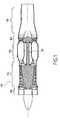
- FIG. 1is a diagrammatic longitudinal section view of a turbojet engine
- FIG. 2is a half-view in fragmentary section of the front portion of a turbojet engine, showing the fan and a low pressure compressor fitted with a casing of the present invention
- FIG. 3is a plan view of a segment of the casing of the present invention with the free ends of the blades shown in cross-section;
- FIG. 4is a section view on line IV—IV of FIG. 3 ;
- FIG. 5is on a larger scale and shows the free end of a blade and the adjacent portion of the casing of the present invention.
- FIG. 1is a diagram of an axial turbojet engine 100 with its moving parts shaded
- the main members of the turbojet enginecomprise, from the upstream end to the downstream end: a fan 102 , a compressor 104 , a combustion chamber 106 , a turbine 108 fitted with its shaft 110 , and an exhaust duct 112 .
- FIG. 2shows a portion of FIG. 1 on a larger scale.
- FIG. 2is a section through half of the front portion 10 of a turbojet engine of the same kind as shown in FIG. 1 , this half being situated on one side of the longitudinal axis 12 forming the axis of symmetry about which various elements rotate, in particular the various moving elements of the turbojet engine.
- FIG. 2shows the fan 102 and the compressor 104 that operates at low pressure.
- the fan 102comprises a series of blades 18 extending radially and mounted on an annular disk 20 : only one of these blades 18 is shown in FIG. 2 . Naturally, the disk 20 and the blades 18 are mounted to rotate about the longitudinal axis 12 of the turbojet engine.
- the flow direction of the air streamdefines an upstream direction (left-hand side of FIG. 1 ) of the downstream portion (right-hand side of FIG. 1 ).
- the compressor 104comprises a plurality of series of blades 22 that are movable in rotation and that are mounted on a disk or drum 24 secured to the disk 20 of the fan 102 .
- FIG. 2there can be seen three series of moving blades 22 having five series of stationary blades 26 mounted between them, being mounted on a casing 28 .
- this casing 28in accordance with the present invention is described below in greater detail with reference to FIGS. 3 to 5 .
- the air flow directionis marked by an arrow 30
- arrow 32shows the direction of rotation of the blades 22 of the compressor 104 .
- the casing 28comprises a main element 34 forming the load-carrying structure of the casing 28 and separating the air flow section (filament of flow) from the outside: this main element 34 thus corresponds essentially to the form of a conventional prior art casing.
- the main element 34has annular grooves 36 disposed facing each of the series of blades 22 that is to be treated.
- FIG. 3shows an axis 12 , which is parallel to the longitudinal axis 12 of FIG. 2 ).
- the annular groove 36serves as a housing for an assembly comprising a plate 38 made of cellular material having tubular cells (honeycomb made from expanded sheets that are stuck to one another), a covering 40 forming a skin placed on the face of the plate 38 that faces away from the blades 22 , and a metal sheet 42 disposed between the covering 40 of the plate 38 and the bottom of the annular groove 36 .
- the covering 40has holes 40 a placed in line with some of the cells of the plate 38 which thus constitute open cells 38 a . However, not all of the cells in the plate 38 are open at their bottom ends in the plate 38 via holes 40 a , so there remain closed cells 38 b , as well.
- the closed cells 38 bare closed by the covering 40 at their ends facing away from the blades 22 , while their ends facing towards the blades 22 are open.
- the closed cells 38 bare lined with a wear material 44 thus enabling the plate 38 to act as an abradable element, i.e. an element which is worn away or removed by the free ends of the blades 22 , where appropriate (see FIG. 5 ).
- the metal sheet 42is pierced by orifices 42 a situated in line with the holes 40 a in the covering 40 . Nevertheless, the position, the distribution, and the frequency of the orifices 42 a can be modified so that the pierced metal sheet 22 contributes to improving noise or acoustic performance.
- the above-described arrangementleads to a dead cavity 46 being formed between the bottom of the groove 36 and the metal sheet 42 , which cavity performs an air recirculation function as described in greater detail below.
- the plate 38thus has rows 38 c of cells 38 a , 38 b , one of these rows 38 c being visible in section in FIG. 4 .
- These rows of cells 38 care oriented in such a manner as to form an angle ⁇ with the axis 12 ′ parallel to the longitudinal axis 12 .
- This angle ⁇ which is advantageously acutemay lie in the range 0° to 90°, and preferably in the range 15° to 45°, and it is preferably substantially equal to 30°.
- This angle ⁇is selected to be close to the section setting angle, i.e. the angle formed between the longitudinal axis 12 (axis of rotation of the turbojet engine) and a straight line situated at the tip of a blade and passing through its leading edge and its trailing edge.
- the cells 38 a , 38 b of the plate 38are also inclined at an angle ⁇ relative to a normal axis 13 which is orthogonal to the longitudinal axis 12 and parallel to a radial or transverse plane of the compressor 104 .
- This angle ⁇may lie in the range ⁇ 90° to +90° (for circumferential grooving), and it depends on the speed vector at the tip of the blade.
- the cells 38 a , 38 bare hexagonal in section, however it should be understood that other shapes could naturally be used including: rectangular, flexible, multiple wave, reinforced hexagonal, cylindrical, sinusoidal, square, cruciform, offset hexagonal, and stiffened square (see in particular page 7 of French standard PR L 19-000 relating to an overall view of cellular materials having tubular cells for use in the fields of aviation and space).
- the sheets used for making the honeycomb plate 38are made of aluminum alloy, titanium alloy, steel, or other metals, or indeed out of a non-metallic composite material.
- the length l of the cells 38 a , 38 bmay also be modified as a function of the result that it is desired to obtain. It should be understood that the dead cavity 46 enables air to recirculate corresponding to air inlet and outlet via the channels constituted by the open cells 38 a.
- the free tips of the blades 22sweep over the various cells of the plate 38 , thereby exposing the open cells 38 a to pressure conditions that differ depending on the position of each blade 22 .
- the face 22 a of the blade 22corresponds to its low pressure side
- the face 22 bcorresponds to its side that is subjected to a higher pressure
- arrow 32indicating the direction of rotation of the blade 22 .
- the open cell 38 a 1is situated on the high pressure side 22 b of the blade 22 1 , however as the blade advances in rotation in the direction of arrow 32 , the open cell 38 a 1 will subsequently be subjected to pressure corresponding to the low pressure of the face 22 a corresponding to the subsequent position of the blade 22 1 and, as was the blade 38 a 1 when the blade 22 1 was in its initial position.
- the open cell 38 a 2 that was initially subjected to pressure corresponding to the high pressure side 22 b of the blade 22generates a kind of air jet (arrow 48 ) beside the face 22 a subjected to low pressure of the blade 22 when the blade passes over said cell 38 a 2 , because of the previous entry of a flow of air (arrow 50 ) beside the face 22 b of the blade 22 that is subjected to high pressure.
- the mean dimension d (see FIG. 5 ) of the section of the cells 38 a , 38 bis preferably substantially equal to the thickness e of the blades 22 .
- the length l of the cells in the plate 38is preferably not less than the dimension d, and preferably lies in the range two to ten times said dimension d.
- the wear material 44may be constituted by a multitude of different materials amongst which the preferred materials belong to the group formed by: resins, silicones, silicone resins, advantageously with added hollow beads, in particular glass beads.
- Resins filled with glass beadscan be used, such as the resin known as “Minnesota Ec 3524”. Silicone resins filled with hollow glass beads include, in particular, a resin known as “RTV 147 / 148 ”.
- an offsetis shown between the positions of the open cells 38 a and the closed cells 38 b once every seven rows of cells 38 c , however other dispositions could also be selected.
- the following parametersare available for optimizing the treatment performed by the casing 28 : density of cells 38 a , 38 b in the plate 38 ; stretched shape of the cells (the shape of their section); the angle formed relative to the flow section (associated with the angle ⁇ ); the ratio between the number of open cells 38 a over the number of closed cells 38 b ; the position and orientation of the open cells and the closed cells; the section size of the open cells 38 a and the positions selected for the open cells 38 a relative to the closed cells 38 b ; the thickness of the honeycomb plate 38 ;
- the assembly 38 , 40 , 42serves fundamentally to stabilize pressure conditions in the air boundary layer in the compressor 104 .
Landscapes
- Engineering & Computer Science (AREA)
- Mechanical Engineering (AREA)
- General Engineering & Computer Science (AREA)
- Life Sciences & Earth Sciences (AREA)
- Sustainable Development (AREA)
- Physics & Mathematics (AREA)
- Fluid Mechanics (AREA)
- Structures Of Non-Positive Displacement Pumps (AREA)
- Turbine Rotor Nozzle Sealing (AREA)
Abstract
Description
- It should also be observed that the positioning of an
assembly groove 36 can be extended to one or more series ofblades 22, to adjacent series of blades, or to certain series of blades, only.
- It should also be observed that the positioning of an
Claims (11)
Applications Claiming Priority (2)
| Application Number | Priority Date | Filing Date | Title |
|---|---|---|---|
| FR0213144 | 2002-10-22 | ||
| FR0213144AFR2846034B1 (en) | 2002-10-22 | 2002-10-22 | CARTER, COMPRESSOR, TURBINE AND COMBUSTION TURBOMOTOR COMPRISING SUCH A CARTER |
Publications (2)
| Publication Number | Publication Date |
|---|---|
| US20050058541A1 US20050058541A1 (en) | 2005-03-17 |
| US6881029B2true US6881029B2 (en) | 2005-04-19 |
Family
ID=32050624
Family Applications (1)
| Application Number | Title | Priority Date | Filing Date |
|---|---|---|---|
| US10/681,265Expired - LifetimeUS6881029B2 (en) | 2002-10-22 | 2003-10-09 | Casing, a compressor, a turbine, and a combustion turbine engine including such a casing |
Country Status (7)
| Country | Link |
|---|---|
| US (1) | US6881029B2 (en) |
| EP (1) | EP1413771B1 (en) |
| JP (1) | JP4148872B2 (en) |
| CA (1) | CA2444982C (en) |
| DE (1) | DE60313929T2 (en) |
| FR (1) | FR2846034B1 (en) |
| RU (1) | RU2324076C2 (en) |
Cited By (17)
| Publication number | Priority date | Publication date | Assignee | Title |
|---|---|---|---|---|
| US20070267246A1 (en)* | 2006-05-19 | 2007-11-22 | Amr Ali | Multi-splice acoustic liner |
| US20080010996A1 (en)* | 2003-07-29 | 2008-01-17 | Pratt & Whitney Canada Corp. | Turbofan case and method of making |
| US20080240917A1 (en)* | 2003-07-29 | 2008-10-02 | Pratt & Whitney Canada Corp. | Turbofan case and method of making |
| US20090074569A1 (en)* | 2007-09-13 | 2009-03-19 | Snecma | Lever for rotating a turbomachine variable-pitch stator vane about its pivot |
| US20090148278A1 (en)* | 2006-08-01 | 2009-06-11 | Siemens Power Generation, Inc. | Abradable coating system |
| US20100034634A1 (en)* | 2005-09-13 | 2010-02-11 | Thomas Scarinci | Acoustic viscous damper for centrifugal gas compressor |
| US20100098532A1 (en)* | 2007-02-14 | 2010-04-22 | Borgwarner Inc. | Compressor housing |
| WO2014106045A1 (en) | 2012-12-28 | 2014-07-03 | United Technologies Corporation | Axial tension system for a gas turbine engine case |
| US20140356142A1 (en)* | 2013-05-29 | 2014-12-04 | Mitsubishi Hitachi Power Systems, Ltd. | Gas Turbine with Honeycomb Seal |
| US8939716B1 (en)* | 2014-02-25 | 2015-01-27 | Siemens Aktiengesellschaft | Turbine abradable layer with nested loop groove pattern |
| US9151175B2 (en) | 2014-02-25 | 2015-10-06 | Siemens Aktiengesellschaft | Turbine abradable layer with progressive wear zone multi level ridge arrays |
| US9243511B2 (en) | 2014-02-25 | 2016-01-26 | Siemens Aktiengesellschaft | Turbine abradable layer with zig zag groove pattern |
| US20160108753A1 (en)* | 2014-10-15 | 2016-04-21 | Techspace Aero S.A. | Insulating Test Engine Hood for a Turbine Engine on a Test Bench |
| US10189082B2 (en) | 2014-02-25 | 2019-01-29 | Siemens Aktiengesellschaft | Turbine shroud with abradable layer having dimpled forward zone |
| US10190435B2 (en) | 2015-02-18 | 2019-01-29 | Siemens Aktiengesellschaft | Turbine shroud with abradable layer having ridges with holes |
| US10273192B2 (en) | 2015-02-17 | 2019-04-30 | Rolls-Royce Corporation | Patterned abradable coating and methods for the manufacture thereof |
| US10408079B2 (en) | 2015-02-18 | 2019-09-10 | Siemens Aktiengesellschaft | Forming cooling passages in thermal barrier coated, combustion turbine superalloy components |
Families Citing this family (21)
| Publication number | Priority date | Publication date | Assignee | Title |
|---|---|---|---|---|
| DE102004055439A1 (en)* | 2004-11-17 | 2006-05-24 | Rolls-Royce Deutschland Ltd & Co Kg | Fluid flow machine with dynamic flow control |
| FR2887890B1 (en)* | 2005-06-30 | 2007-10-12 | Snecma | ABRADABLE MATERIAL COMPOSITION, THERMOMECHANICAL PART OR CASING COMPRISING A COATING AND PROCESS FOR MAKING OR REPAIRING A COATING HAVING THE SAME |
| FR2912789B1 (en)* | 2007-02-21 | 2009-10-02 | Snecma Sa | CARTER WITH CARTER TREATMENT, COMPRESSOR AND TURBOMACHINE COMPRISING SUCH A CARTER. |
| DE102007037924A1 (en)* | 2007-08-10 | 2009-02-12 | Rolls-Royce Deutschland Ltd & Co Kg | Turbomachine with Ringkanalwandausnehmung |
| DE102008011644A1 (en)* | 2008-02-28 | 2009-09-03 | Rolls-Royce Deutschland Ltd & Co Kg | Housing structuring for axial compressor in the hub area |
| DE102008031982A1 (en)* | 2008-07-07 | 2010-01-14 | Rolls-Royce Deutschland Ltd & Co Kg | Turbomachine with groove at a trough of a blade end |
| DE102008037154A1 (en) | 2008-08-08 | 2010-02-11 | Rolls-Royce Deutschland Ltd & Co Kg | Turbomachine |
| EP2418387B1 (en)* | 2010-08-11 | 2015-04-01 | Techspace Aero S.A. | Shroud ring of an axial turbomachine compressor |
| EP2532898A1 (en)* | 2011-06-08 | 2012-12-12 | Siemens Aktiengesellschaft | Axial turbo compressor |
| GB201116029D0 (en)* | 2011-09-16 | 2011-10-26 | Rolls Royce Plc | Abradable panel and method of forming the same |
| EP2951241A4 (en)* | 2013-01-29 | 2016-08-24 | United Technologies Corp | Blade rub material |
| GB201311460D0 (en)* | 2013-06-27 | 2013-08-14 | Rolls Royce Plc | An abradable liner for a gas turbine engine |
| EP2886804B1 (en)* | 2013-12-20 | 2017-08-16 | Safran Aero Boosters SA | Sealing device for a compressor of a turbomachine |
| US10107307B2 (en)* | 2015-04-14 | 2018-10-23 | Pratt & Whitney Canada Corp. | Gas turbine engine rotor casing treatment |
| RU2596894C1 (en)* | 2015-06-02 | 2016-09-10 | Открытое акционерное общество "Уфимское моторостроительное производственное объединение" ОАО "УМПО" | Drum of turbine machine rotor |
| RU2596895C1 (en)* | 2015-06-02 | 2016-09-10 | Открытое акционерное общество "Уфимское моторостроительное производственное объединение" ОАО "УМПО" | Drum of turbine machine rotor |
| DE102018208040A1 (en)* | 2018-05-23 | 2019-11-28 | MTU Aero Engines AG | Seal carrier and turbomachine |
| US10914318B2 (en) | 2019-01-10 | 2021-02-09 | General Electric Company | Engine casing treatment for reducing circumferentially variable distortion |
| CN114080311B (en)* | 2019-07-11 | 2024-04-12 | 赛峰航空器发动机 | Method for manufacturing a component from a composite material by injecting a filling paste into a fibrous texture |
| CN111535869B (en)* | 2020-04-29 | 2022-07-29 | 中国航发湖南动力机械研究所 | Turbine guide |
| BE1028335B1 (en) | 2020-05-20 | 2021-12-20 | Safran Aero Boosters | Low pressure compressor sub-assembly of an aircraft turbomachine |
Citations (10)
| Publication number | Priority date | Publication date | Assignee | Title |
|---|---|---|---|---|
| DE1022745B (en) | 1956-07-20 | 1958-01-16 | Maschf Augsburg Nuernberg Ag | Arrangement to reduce the gap loss in flow machines |
| FR1533120A (en) | 1966-11-02 | 1968-07-12 | Gen Electric | Gas turbine engine turbine air-cooled jacket |
| US3425665A (en) | 1966-02-24 | 1969-02-04 | Curtiss Wright Corp | Gas turbine rotor blade shroud |
| US3867061A (en)* | 1973-12-26 | 1975-02-18 | Curtiss Wright Corp | Shroud structure for turbine rotor blades and the like |
| US4639388A (en)* | 1985-02-12 | 1987-01-27 | Chromalloy American Corporation | Ceramic-metal composites |
| US5161942A (en) | 1990-10-24 | 1992-11-10 | Westinghouse Electric Corp. | Moisture drainage of honeycomb seals |
| US5520508A (en)* | 1994-12-05 | 1996-05-28 | United Technologies Corporation | Compressor endwall treatment |
| US6159578A (en)* | 1998-05-12 | 2000-12-12 | Ngk Insulators, Ltd. | Hexagonal-cell honeycomb structure and method for fixation thereof |
| US6203927B1 (en)* | 1999-02-05 | 2001-03-20 | Siemens Westinghouse Power Corporation | Thermal barrier coating resistant to sintering |
| US6485025B1 (en)* | 2000-11-27 | 2002-11-26 | Neomet Limited | Metallic cellular structure |
Family Cites Families (4)
| Publication number | Priority date | Publication date | Assignee | Title |
|---|---|---|---|---|
| GB1518293A (en)* | 1975-09-25 | 1978-07-19 | Rolls Royce | Axial flow compressors particularly for gas turbine engines |
| GB2158879B (en)* | 1984-05-19 | 1987-09-03 | Rolls Royce | Preventing surge in an axial flow compressor |
| RU2148732C1 (en)* | 1998-05-05 | 2000-05-10 | Открытое акционерное общество Самарский научно-технический комплекс им. Н.Д. Кузнецова | Turbo-machine stage |
| RU2176333C2 (en)* | 2000-01-10 | 2001-11-27 | Открытое акционерное общество "Авиадвигатель" | Device for air bleed between compressors of gas- turbine engine |
- 2002
- 2002-10-22FRFR0213144Apatent/FR2846034B1/ennot_activeExpired - Fee Related
- 2003
- 2003-10-09USUS10/681,265patent/US6881029B2/ennot_activeExpired - Lifetime
- 2003-10-16CACA2444982Apatent/CA2444982C/ennot_activeExpired - Lifetime
- 2003-10-17JPJP2003357769Apatent/JP4148872B2/ennot_activeExpired - Lifetime
- 2003-10-20RURU2003131385/06Apatent/RU2324076C2/enactive
- 2003-10-21DEDE60313929Tpatent/DE60313929T2/ennot_activeExpired - Lifetime
- 2003-10-21EPEP03292610Apatent/EP1413771B1/ennot_activeExpired - Lifetime
Patent Citations (11)
| Publication number | Priority date | Publication date | Assignee | Title |
|---|---|---|---|---|
| DE1022745B (en) | 1956-07-20 | 1958-01-16 | Maschf Augsburg Nuernberg Ag | Arrangement to reduce the gap loss in flow machines |
| US3425665A (en) | 1966-02-24 | 1969-02-04 | Curtiss Wright Corp | Gas turbine rotor blade shroud |
| FR1533120A (en) | 1966-11-02 | 1968-07-12 | Gen Electric | Gas turbine engine turbine air-cooled jacket |
| US3867061A (en)* | 1973-12-26 | 1975-02-18 | Curtiss Wright Corp | Shroud structure for turbine rotor blades and the like |
| US4639388A (en)* | 1985-02-12 | 1987-01-27 | Chromalloy American Corporation | Ceramic-metal composites |
| US5161942A (en) | 1990-10-24 | 1992-11-10 | Westinghouse Electric Corp. | Moisture drainage of honeycomb seals |
| US5520508A (en)* | 1994-12-05 | 1996-05-28 | United Technologies Corporation | Compressor endwall treatment |
| EP0716218A1 (en) | 1994-12-05 | 1996-06-12 | United Technologies Corporation | Compressor shroud |
| US6159578A (en)* | 1998-05-12 | 2000-12-12 | Ngk Insulators, Ltd. | Hexagonal-cell honeycomb structure and method for fixation thereof |
| US6203927B1 (en)* | 1999-02-05 | 2001-03-20 | Siemens Westinghouse Power Corporation | Thermal barrier coating resistant to sintering |
| US6485025B1 (en)* | 2000-11-27 | 2002-11-26 | Neomet Limited | Metallic cellular structure |
Cited By (31)
| Publication number | Priority date | Publication date | Assignee | Title |
|---|---|---|---|---|
| US7739866B2 (en) | 2003-07-29 | 2010-06-22 | Pratt & Whitney Canada Corp. | Turbofan case and method of making |
| US20080010996A1 (en)* | 2003-07-29 | 2008-01-17 | Pratt & Whitney Canada Corp. | Turbofan case and method of making |
| US20080014083A1 (en)* | 2003-07-29 | 2008-01-17 | Pratt & Whitney Canada Corp. | Turbofan case and method of making |
| US20080240917A1 (en)* | 2003-07-29 | 2008-10-02 | Pratt & Whitney Canada Corp. | Turbofan case and method of making |
| US7797922B2 (en) | 2003-07-29 | 2010-09-21 | Pratt & Whitney Canada Corp. | Gas turbine engine case and method of making |
| US7793488B2 (en) | 2003-07-29 | 2010-09-14 | Pratt & Whitney Canada Corp. | Turbofan case and method of making |
| US7565796B2 (en) | 2003-07-29 | 2009-07-28 | Pratt & Whitney Canada Corp. | Turbofan case and method of making |
| US7770378B2 (en) | 2003-07-29 | 2010-08-10 | Pratt & Whitney Canada Corp. | Turbofan case and method of making |
| US20100034634A1 (en)* | 2005-09-13 | 2010-02-11 | Thomas Scarinci | Acoustic viscous damper for centrifugal gas compressor |
| US7722316B2 (en) | 2005-09-13 | 2010-05-25 | Rolls-Royce Power Engineering Plc | Acoustic viscous damper for centrifugal gas compressor |
| US20070267246A1 (en)* | 2006-05-19 | 2007-11-22 | Amr Ali | Multi-splice acoustic liner |
| US8602156B2 (en)* | 2006-05-19 | 2013-12-10 | United Technologies Corporation | Multi-splice acoustic liner |
| US7686570B2 (en)* | 2006-08-01 | 2010-03-30 | Siemens Energy, Inc. | Abradable coating system |
| US20090148278A1 (en)* | 2006-08-01 | 2009-06-11 | Siemens Power Generation, Inc. | Abradable coating system |
| US20100098532A1 (en)* | 2007-02-14 | 2010-04-22 | Borgwarner Inc. | Compressor housing |
| US20090074569A1 (en)* | 2007-09-13 | 2009-03-19 | Snecma | Lever for rotating a turbomachine variable-pitch stator vane about its pivot |
| US8197190B2 (en)* | 2007-09-13 | 2012-06-12 | Snecma | Lever for rotating a turbomachine variable-pitch stator vane about its pivot |
| EP2938843A4 (en)* | 2012-12-28 | 2016-03-23 | United Technologies Corp | AXIAL TENSION SYSTEM FOR GAS TURBINE HOUSING |
| WO2014106045A1 (en) | 2012-12-28 | 2014-07-03 | United Technologies Corporation | Axial tension system for a gas turbine engine case |
| US10190499B2 (en) | 2012-12-28 | 2019-01-29 | United Technologies Corporation | Axial tension system for a gas turbine engine case |
| US9822659B2 (en)* | 2013-05-29 | 2017-11-21 | Mitsubishi Hitachi Power Systems, Ltd. | Gas turbine with honeycomb seal |
| US20140356142A1 (en)* | 2013-05-29 | 2014-12-04 | Mitsubishi Hitachi Power Systems, Ltd. | Gas Turbine with Honeycomb Seal |
| US9243511B2 (en) | 2014-02-25 | 2016-01-26 | Siemens Aktiengesellschaft | Turbine abradable layer with zig zag groove pattern |
| US9151175B2 (en) | 2014-02-25 | 2015-10-06 | Siemens Aktiengesellschaft | Turbine abradable layer with progressive wear zone multi level ridge arrays |
| US8939716B1 (en)* | 2014-02-25 | 2015-01-27 | Siemens Aktiengesellschaft | Turbine abradable layer with nested loop groove pattern |
| US10189082B2 (en) | 2014-02-25 | 2019-01-29 | Siemens Aktiengesellschaft | Turbine shroud with abradable layer having dimpled forward zone |
| US20160108753A1 (en)* | 2014-10-15 | 2016-04-21 | Techspace Aero S.A. | Insulating Test Engine Hood for a Turbine Engine on a Test Bench |
| US10458272B2 (en)* | 2014-10-15 | 2019-10-29 | Safran Aero Boosters Sa | Insulating test engine hood for a turbine engine on a test bench |
| US10273192B2 (en) | 2015-02-17 | 2019-04-30 | Rolls-Royce Corporation | Patterned abradable coating and methods for the manufacture thereof |
| US10190435B2 (en) | 2015-02-18 | 2019-01-29 | Siemens Aktiengesellschaft | Turbine shroud with abradable layer having ridges with holes |
| US10408079B2 (en) | 2015-02-18 | 2019-09-10 | Siemens Aktiengesellschaft | Forming cooling passages in thermal barrier coated, combustion turbine superalloy components |
Also Published As
| Publication number | Publication date |
|---|---|
| EP1413771B1 (en) | 2007-05-23 |
| DE60313929D1 (en) | 2007-07-05 |
| EP1413771A1 (en) | 2004-04-28 |
| FR2846034B1 (en) | 2006-06-23 |
| RU2324076C2 (en) | 2008-05-10 |
| CA2444982A1 (en) | 2004-04-22 |
| CA2444982C (en) | 2011-08-30 |
| FR2846034A1 (en) | 2004-04-23 |
| JP2004278516A (en) | 2004-10-07 |
| JP4148872B2 (en) | 2008-09-10 |
| US20050058541A1 (en) | 2005-03-17 |
| DE60313929T2 (en) | 2008-01-17 |
| RU2003131385A (en) | 2005-04-10 |
Similar Documents
| Publication | Publication Date | Title |
|---|---|---|
| US6881029B2 (en) | Casing, a compressor, a turbine, and a combustion turbine engine including such a casing | |
| EP2055898B1 (en) | Gas turbine engine with circumferential array of airfoils with platform cooling | |
| EP1493900B1 (en) | Guide vane assembly for a gas turbine engine | |
| US7320575B2 (en) | Methods and apparatus for aerodynamically self-enhancing rotor blades | |
| EP3361053B1 (en) | Grooved shroud casing treatment for high pressure compressor in a turbine engine | |
| EP1939397B1 (en) | Turbine nozzle with bullnose step-down platform | |
| US10047620B2 (en) | Circumferentially varying axial compressor endwall treatment for controlling leakage flow therein | |
| US3533711A (en) | Cooled vane structure for high temperature turbines | |
| US6435815B2 (en) | Aerofoil for an axial flow turbo machine | |
| EP3150803B1 (en) | Airfoil and method of cooling | |
| US7874794B2 (en) | Blade row for a rotary machine and method of fabricating same | |
| US20160153465A1 (en) | Axial compressor endwall treatment for controlling leakage flow therein | |
| EP1756409B1 (en) | Shockwave-induced boundary layer bleed for transonic gas turbine | |
| CN112983885B (en) | Shroud for a splitter and rotor airfoil of a fan of a gas turbine engine | |
| US20170298742A1 (en) | Turbine engine airfoil bleed pumping | |
| US6695582B2 (en) | Turbine blade wall cooling apparatus and method of fabrication | |
| US10502220B2 (en) | Method for improving turbine compressor performance | |
| CA2928603A1 (en) | Composite splitter lip for axial turbomachine compressor | |
| US7690896B2 (en) | Gas turbine disk slots and gas turbine engine using same | |
| EP3693541B1 (en) | Gas turbine rotor disk having scallop shield feature | |
| EP1482126B1 (en) | Rotor assembly for a gas turbine engine | |
| CN114294263B (en) | Fan blade disc structure and turbofan engine | |
| GB2112869A (en) | Cooled airfoil | |
| US20220090504A1 (en) | Rotor blade for a gas turbine engine having a metallic structural member and a composite fairing | |
| RU10425U1 (en) | DRIVE GAS TURBINE ENGINE |
Legal Events
| Date | Code | Title | Description |
|---|---|---|---|
| AS | Assignment | Owner name:SNECMA MOTEURS, FRANCE Free format text:ASSIGNMENT OF ASSIGNORS INTEREST;ASSIGNORS:LE BIEZ, PHILIPPE;LEBRET, YANN;MONS, CLAUDE;REEL/FRAME:014587/0291 Effective date:20030924 | |
| STCF | Information on status: patent grant | Free format text:PATENTED CASE | |
| FEPP | Fee payment procedure | Free format text:PAYOR NUMBER ASSIGNED (ORIGINAL EVENT CODE: ASPN); ENTITY STATUS OF PATENT OWNER: LARGE ENTITY | |
| AS | Assignment | Owner name:SNECMA, FRANCE Free format text:CHANGE OF NAME;ASSIGNOR:SNECMA MOTEURS;REEL/FRAME:020609/0569 Effective date:20050512 Owner name:SNECMA,FRANCE Free format text:CHANGE OF NAME;ASSIGNOR:SNECMA MOTEURS;REEL/FRAME:020609/0569 Effective date:20050512 | |
| FPAY | Fee payment | Year of fee payment:4 | |
| FPAY | Fee payment | Year of fee payment:8 | |
| FPAY | Fee payment | Year of fee payment:12 | |
| AS | Assignment | Owner name:SAFRAN AIRCRAFT ENGINES, FRANCE Free format text:CHANGE OF NAME;ASSIGNOR:SNECMA;REEL/FRAME:046479/0807 Effective date:20160803 | |
| AS | Assignment | Owner name:SAFRAN AIRCRAFT ENGINES, FRANCE Free format text:CORRECTIVE ASSIGNMENT TO CORRECT THE COVER SHEET TO REMOVE APPLICATION NOS. 10250419, 10786507, 10786409, 12416418, 12531115, 12996294, 12094637 12416422 PREVIOUSLY RECORDED ON REEL 046479 FRAME 0807. ASSIGNOR(S) HEREBY CONFIRMS THE CHANGE OF NAME;ASSIGNOR:SNECMA;REEL/FRAME:046939/0336 Effective date:20160803 |