US6880199B1 - Extraction cleaning with collapsible tanks - Google Patents
Extraction cleaning with collapsible tanksDownload PDFInfo
- Publication number
- US6880199B1 US6880199B1US10/065,255US6525502AUS6880199B1US 6880199 B1US6880199 B1US 6880199B1US 6525502 AUS6525502 AUS 6525502AUS 6880199 B1US6880199 B1US 6880199B1
- Authority
- US
- United States
- Prior art keywords
- cleaning machine
- machine according
- recovery tank
- tank
- tanks
- Prior art date
- Legal status (The legal status is an assumption and is not a legal conclusion. Google has not performed a legal analysis and makes no representation as to the accuracy of the status listed.)
- Expired - Lifetime, expires
Links
Images


Classifications
- A—HUMAN NECESSITIES
- A47—FURNITURE; DOMESTIC ARTICLES OR APPLIANCES; COFFEE MILLS; SPICE MILLS; SUCTION CLEANERS IN GENERAL
- A47L—DOMESTIC WASHING OR CLEANING; SUCTION CLEANERS IN GENERAL
- A47L11/00—Machines for cleaning floors, carpets, furniture, walls, or wall coverings
- A47L11/40—Parts or details of machines not provided for in groups A47L11/02 - A47L11/38, or not restricted to one of these groups, e.g. handles, arrangements of switches, skirts, buffers, levers
- A47L11/408—Means for supplying cleaning or surface treating agents
- A47L11/4083—Liquid supply reservoirs; Preparation of the agents, e.g. mixing devices
- A—HUMAN NECESSITIES
- A47—FURNITURE; DOMESTIC ARTICLES OR APPLIANCES; COFFEE MILLS; SPICE MILLS; SUCTION CLEANERS IN GENERAL
- A47L—DOMESTIC WASHING OR CLEANING; SUCTION CLEANERS IN GENERAL
- A47L11/00—Machines for cleaning floors, carpets, furniture, walls, or wall coverings
- A47L11/29—Floor-scrubbing machines characterised by means for taking-up dirty liquid
- A47L11/30—Floor-scrubbing machines characterised by means for taking-up dirty liquid by suction
- A—HUMAN NECESSITIES
- A47—FURNITURE; DOMESTIC ARTICLES OR APPLIANCES; COFFEE MILLS; SPICE MILLS; SUCTION CLEANERS IN GENERAL
- A47L—DOMESTIC WASHING OR CLEANING; SUCTION CLEANERS IN GENERAL
- A47L11/00—Machines for cleaning floors, carpets, furniture, walls, or wall coverings
- A47L11/34—Machines for treating carpets in position by liquid, foam, or vapour, e.g. by steam
Definitions
- the inventionrelates to an upright extraction cleaning machine incorporating a flexible tank for holding a liquid.
- the inventionrelates to an upright extraction cleaning machine incorporating multiple collapsible or flexible tanks for holding clean water, dirty water, detergent, oxidizing solution and carpet protectant.
- an extraction cleaning machinecomprises a housing, a cleaning solution dispensing system mounted to the housing for depositing a cleaning solution on a surface to be cleaned, and a fluid recovery system mounted to the housing for recovering expended cleaning solution from the surface to be cleaned.
- the dispensing systemincludes a dispensing tank for holding solution to be dispensed.
- the recovery systemalso includes a recovery tank for recovered solution.
- the recovery tankis flexible to expand as recovered fluid is received therein.
- the dispensing tankcomprises a flexible bladder that is collapsible as cleaning fluid is dispensed therefrom.
- the dispensing tank and the recovery tankare adjacent to one another in a common space and positioned so that the dispensing tank collapses as the recovery tank expands.
- the cleaning solution dispensing systemfurther comprises additional tanks for detergent and carpet treatment.
- the additional tanks for detergent and carpet treatmenteach comprise a flexible bladder that collapses as solution therein is dispensed therefrom.
- the tanksare mounted in a confined shell in the housing.
- the tanksare both located in a base module of an upright deep cleaner.
- the tanksare both located in an upright handle in an upright deep cleaner.
- the tankscan be arranged side by side in horizontal alignment or in vertically stacked alignment.
- FIG. 1is a schematic representation of the extraction cleaning system incorporating flexible tanks according to the invention.
- FIG. 2is a schematic representation of a further embodiment of an extraction cleaning system incorporating flexible tanks according to the invention.
- FIG. 3is a partial cutaway rear perspective view of an upright extraction cleaning machine incorporating multiple flexible tanks into a base module according to the invention.
- FIG. 4is a partial cutaway rear perspective view of an upright extraction cleaning machine incorporating multiple flexible tanks into a base module according to another embodiment of the invention.
- FIG. 5is a partial cutaway perspective view of an upright extraction cleaning machine incorporating multiple flexible tanks into an upright handle according to another embodiment of the invention.
- FIG. 6is a partial cutaway perspective view of an upright extraction cleaning machine incorporating multiple flexible tanks into an upright handle according to another embodiment of the invention.
- FIG. 7is a perspective view of the flexible tank assembly shown in FIG. 3 .
- FIG. 8is an exploded front view of the flexible tank assembly shown in FIG. 7 .
- FIG. 9is an exploded side view of the flexible tank assembly shown in FIGS. 7-8 .
- FIG. 10is a cross-sectional view of the flexible tank assembly shown in FIGS. 7-9 .
- FIG. 11is a perspective view in section of the flexible tank assembly shown in FIGS. 7-10 .
- FIG. 12is a perspective view of the flexible tank assembly shown in FIG. 4 .
- FIG. 13is an exploded front view of the flexible tank assembly shown in FIG. 12 .
- FIG. 14is an exploded side view of the flexible tank assembly shown in FIGS. 12-13 .
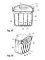
- FIG. 15is a cross-sectional view of the flexible tank assembly shown in FIGS. 12-14 .
- FIG. 16is a perspective view in section of the flexible tank assembly shown in FIGS. 12 - 15 .
- the extraction cleaning system 100includes a cleaning solution dispensing system 110 and a fluid recovery system 130 incorporating multiple flexible tanks.
- the cleaning solution dispensing system 110includes at least one and preferably a plurality of flexible supply tanks or bladders 112 , 116 , 120 for holding any of the number of desired fluids for dispensing onto a surface to be cleaned.
- the fluidscan include water or other cleaning or protecting agents such as detergent, anti-allergens, carpet protectant, an oxidizing solution and other commonly known carpet and upholstery treatment solutions.
- Each of the supply tanks or bladders 112 , 116 , 120is fluidly connected to a solution pump 124 through respective adjustable valves 114 , 118 and 122 .
- the pump 124is further fluidly connected to a dispensing nozzle 128 through an actuation trigger valve 126 .
- the fluids released to the pump 124 by the valves 114 , 118 , 122are sprayed onto the surface being cleaned through the dispensing nozzle 128 .
- the supply tanks 112 , 116 , 120will tend to collapse.
- the volume occupied by the supply tanks 112 , 116 , 120will tend to decrease in proportion to the decrease in the volume of fluid in the tanks.
- Each of the supply tanks 112 , 116 and 120has an opening 125 , typically, covered by a cap for filling the tanks.
- the fluid recovery system 130 shown in FIG. 1is commonly known as a “dirty air system” in that the fluid passing through a suction source 134 such as an impeller has not previously passed through any filtering or separation system to remove contaminants.
- a suction nozzle 132is placed proximate to a surface being cleaned and a suction force is applied to draw liquid and debris from the surface.
- the suction nozzle 132is fluidly connected to the intake of a suction source 134 .
- the output of the suction source 134is fluidly connected to an air/liquid separator 136 .
- the air/liquid separator 136provides a means whereby a liquid such as a dirty cleaning solution, including any particulate matter drawn through the suction nozzle 132 , is separated from an exhaust air flow. The exhaust air flow is then released to atmosphere.
- the air/liquid separator 136can be, but need not be, the separator disclosed in U.S. Pat. No. 6,167,586.
- the liquid separated from the exhaust air flowis retained in a flexible recovery tank or bladder 138 .
- the recovery tank 138can be fluidly connected to a separately formed air/liquid separator 136 , or, in some embodiments, the recovery tank 138 and air/liquid separator 136 can be integrally formed with the recovery tank.
- the recovery tankcan have a removable drain plug 139 for draining the tank.
- the flexible recovery tank 138will increase in volume in proportion to the volume of liquid deposited therein.
- the volume of liquid deposited in the recovery tank 138will be equal to or less than the volume of liquid dispensed by the solution tanks 112 , 116 , 120 .
- Some volume of the liquid dispensedgenerally remains on the surface being cleaned or evaporates.
- the recovery tankis preferably biased into the expanded condition. In one embodiment, the natural resilience of the material that forms the recovery tank 138 biases the recovery tank into the expanded condition. In another embodiment, a spring can be placed inside the recovery tank to bias the recovery tank into the expanded condition.
- the recovery tank 138is located with the solution tanks 112 , 116 , 120 on the same portion of the extraction cleaner.
- a rigid housingcontains the recovery tank 138 and solution tanks 112 , 116 , 120 .
- the housingis sized to hold an empty recovery tank 138 and full solution tanks 112 , 116 , 120 , and vice versa.
- the size of the tanks 112 , 116 , 120will decrease sufficiently for recovery tank 138 to expand into the space vacated by the tanks 112 , 116 , 120 as recovered liquid is deposited in the recovery tank 138 .
- the housingcan thus be much smaller than the combined full volume of the recovery tank 138 and the solution tanks 112 , 116 , 120 .
- one or more of the solution tanksis mounted in a second housing.
- a “clean air” extraction cleaning system 100comprises a solution dispensing system 110 and a recovery system 140 .
- the solution dispensing system 110is the same as disclosed with respect to the “dirty air” system of FIG. 1 .
- the recovery system 140differs in the arrangement of elements in the flow path of the recovered fluid.
- a suction nozzle 142 placed proximate to a surface to be cleanedis fluidly connected to an air/liquid separator 146 .
- the air/liquid separator 146is further fluidly connected to a suction source 144 and to a flexible recovery tank or bladder 148 .
- An exhaust of the suction source 144is vented to the atmosphere.
- the air/liquid separator 146 and recovery tank 148can be integrally or separately formed. Further, the recovery tank 148 is located in the same confined space with the solution tanks 112 , 116 , 120 and, expands as it fills with recovered liquid to occupy the space vacated by the solution tanks as solution is dispensed onto the surface being cleaned.
- an upright extraction cleaning machine 100has a floor traveling base module 102 , an upright handle 104 pivotally mounted to the base module 102 and a pair of wheels 106 supporting the extraction cleaning machine 100 .
- a solution dispensing/recovery tank assembly 150includes a rigid housing 200 having a cover 210 with a pivotal handle 212 , the housing 200 being carried by the base module 102 .
- the flexible tanks/bladders 112 , 116 , 120 , 148each have a substantially horizontal orientation so that they can be stacked one upon the other and carried within the rigid housing 200 .
- the recovery tank 148presses down upon the other bladders as it fills with recovered liquid.
- the assembly 150further comprises a weight or spring (not shown) bearing upon the solution dispensing tanks 112 , 116 , 120 to encourage their collapse upon dispensing their solution and to facilitate expansion of the uppermost bladder 148 .
- a further embodiment of the upright extraction cleaning machine 100has a solution dispensing/recovery tank assembly 160 including a rigid housing 200 on the base module 102 .
- the housing 200is partially cut away.
- the assembly 160further comprises flexible tanks/bladders 112 , 116 , 120 , 148 , each having a substantially vertical orientation and arranged side by side within rigid housing 200 .
- the assembly 160can include spring elements (not shown) bearing upon the solution dispensing bladders 112 , 116 , 120 to encourage their collapse upon dispensing the solution and to facilitate expansion of the recovery tank/bladder. For instance, the spring elements are biased against the bladders 112 , 116 , 120 away from bladder 148 . It is also anticipated that air pressure developed by the suction source, particularly the exhaust of the suction source, can be directed into the housing 200 or the recovery bladder 148 to aid in expansion of the recovery bladder and/or collapse of the solution dispensing bladders. This pressure on the solution dispensing bladders by the spring elements can be sufficient to pressurize the cleaning solution so that it can flow to the dispensing nozzle 128 without the need for the pump 124 . Thus, the pump 124 is optional in this embodiment.
- a solution dispensing/recovery tank assembly 170is contained within a rigid housing 108 of the upright handle 104 of the upright extraction cleaning machine 100 .
- the assembly 170comprises a plurality of flexible tanks/bladders 112 , 116 , 120 and 148 , each having a generally vertical orientation and aligned side by side within the upright handle 104 of the upright extraction cleaning machine 100 , much in the fashion of the assembly 160 of FIG. 4.
- a portion of the housing 108is broken away to show the arrangement of the bladders 112 , 116 , 120 148 in the housing 108 .
- a solution dispensing/recovery tank assembly 180is contained within a rigid handle housing 108 of the upright handle 104 of the upright extraction cleaning machine 100 .
- the assembly 180comprises a plurality of flexible tanks/bladders 112 , 116 , 120 148 each having a generally horizontal orientation and stacked within the upright handle 104 of the upright extraction cleaning machine 100 , much in the fashion of the assembly 150 of FIG. S.
- a portion of the housing 108is broken away to show the arrangement of the bladders 112 , 116 , 120 and 148 in the housing 108 .
- the cleaning fluidcan flow from the flexible tanks/bladders 112 , 116 and 120 by gravity to the dispensing nozzle 128 without the aid of a pump 124 .
- the cleaning fluidcan be pressurized to flow cleaning solution to the spray nozzle 128 by springs or air pressure as described above.
- FIGS. 7-11depict the solution dispensing/recovery tank assembly 150 .
- the flexible tanks/bladders 112 , 116 , 120 and 148are suspended from a lid 210 of the rigid housing 200 .
- a removable frame 220carries the bladders 112 , 116 , 120 and 148 by a pair of retention straps 224 .
- the frame 220is removably mounted to the lid 210 , and can include a filler neck 222 for fluidly connecting to the solution dispensing or recovery systems.
- Each of the tanks 112 , 116 , 120 and 148includes inlet openings and outlet ports for filling and emptying the tanks, respectively.
- the inlet openings of each solution dispensing tank 112 , 116 , 120 and 148is for the user to fill the solution dispensing tank with the appropriate fluid.
- the outlet ports of the dispensing tanksare fluidly connected to the solution dispensing system.
- the inlet port of the recovery tank 148is fluidly connected to the recovery system, while the outlet port is accessible for emptying the recovery tank by the user.
- An air/liquid separator 24that can be, but need not be, the separator disclosed in U.S. Pat. No. 6,167,586 is mounted in the lid 210 for separation of the soiled liquid from air.
- Outlet port 244is disclosed for tank 120 .
- Outlet port 244is anticipated by way of example to be a self-closing valve that opens and fluidly connects to the dispensing system when the assembly 150 is inserted in the base module 102 .
- a bladder having an inlet fill opening and a dispensing outlet portis disclosed in U.S. Pat. No. 6,230,362, incorporated herein by reference.
- Interior springs 152are mounted with the recovery tank 148 to bias the recovery tank into an open position, and, at the same time, to bias the bladders 112 , 116 and 120 into a collapsed position.
- FIGS. 12-16depict the solution dispensing/recovery tank assembly 160 .
- the flexible tanks/bladders 112 , 116 , 120 and 148are suspended from the lid 210 of the rigid housing 200 .
- the bladders 112 , 116 , 120 and 148are suspended directly from the frame 220 which is removably mounted to the lid 210 .
- a pair of elastic bandsare stretched around the bladders 112 , 116 and 120 to bias these bladders into a collapsed condition and thus pressurize the liquid in these bladders.
- Each of the tanks 112 , 116 , 120 and 148includes inlet openings and outlet ports (not shown) for filling and emptying the tanks respectively.
- the inlet openings of each solution dispensing tankenable the user to fill the solution dispensing tank with the appropriate fluid.
- the outlet ports of the dispensing tanksare fluidly connected to the solution dispensing system.
- the inlet opening of the recovery tank 148is fluidly connected to the recovery system, while the outlet port is accessible for emptying the recovery tank 148 by the user.
- outlet ports 244 in bladders 112 , 116 and 120function as described above with reference to FIGS. 10-11 and as described in U.S. Pat. Nos. 6,230,362 and 6,167,586 which are incorporated herein by reference.
- the solution dispensing tanks and recovery tankare all located in a single housing, whether it be on the base module or the upright handle of the upright extraction cleaner. It is further anticipated that one or more of the tanks can be located remotely from the remaining tanks. For example, one or more tanks can be located in the upright handle while the remaining tanks are located in the base module.
- each of the flexible bladder assemblies previously describedis in communication with a socket formed in the portable upright extraction cleaning unit.
- a plurality of receivers corresponding to the fittings on outlet openings of the flexible bladdersare located along the bottom wall of the socket.
- the flexible bladder assemblyis lifted by the operator such as by the handle 212 and carried to a convenient workspace where the bladders are filled with desired liquids, cleaning agents, or upholstery protectants through respective fill openings in each flexible bladder.
- the recovery tankcan also be emptied at this time.
- the flexible bladder assemblyis carried by the handle 212 and placed in the socket area of the upright extraction cleaner so that the fittings on the outlet openings correspond with and communicate with receivers in the extraction cleaner to fluidly connect the tanks with a respective dispensing or recovery system in the same manner as described in U.S. Pat. No. 6,167,586.
Landscapes
- Cleaning By Liquid Or Steam (AREA)
Abstract
Description
Claims (34)
Priority Applications (1)
| Application Number | Priority Date | Filing Date | Title |
|---|---|---|---|
| US10/065,255US6880199B1 (en) | 2001-10-01 | 2002-09-30 | Extraction cleaning with collapsible tanks |
Applications Claiming Priority (2)
| Application Number | Priority Date | Filing Date | Title |
|---|---|---|---|
| US32632201P | 2001-10-01 | 2001-10-01 | |
| US10/065,255US6880199B1 (en) | 2001-10-01 | 2002-09-30 | Extraction cleaning with collapsible tanks |
Publications (1)
| Publication Number | Publication Date |
|---|---|
| US6880199B1true US6880199B1 (en) | 2005-04-19 |
Family
ID=34437096
Family Applications (1)
| Application Number | Title | Priority Date | Filing Date |
|---|---|---|---|
| US10/065,255Expired - LifetimeUS6880199B1 (en) | 2001-10-01 | 2002-09-30 | Extraction cleaning with collapsible tanks |
Country Status (1)
| Country | Link |
|---|---|
| US (1) | US6880199B1 (en) |
Cited By (26)
| Publication number | Priority date | Publication date | Assignee | Title |
|---|---|---|---|---|
| US20030019071A1 (en)* | 2001-07-30 | 2003-01-30 | Field Bruce F | Cleaner cartridge |
| US20040040102A1 (en)* | 2001-07-30 | 2004-03-04 | Tennant Company | Foamed cleaning liquid dispensing system |
| US20040221407A1 (en)* | 2001-07-30 | 2004-11-11 | Tennant Company | Cleaning liquid dispensing system |
| US20050132523A1 (en)* | 2003-12-18 | 2005-06-23 | Kegg Steven W. | Solution distribution arrangement for a cleaning machine |
| US20050144751A1 (en)* | 2004-01-07 | 2005-07-07 | Kegg Steven W. | Adjustable flow rate valve for a cleaning apparatus |
| US20060032519A1 (en)* | 2001-07-30 | 2006-02-16 | Tennant Company | Cleaning liquid dispensing in a mobile hard surface cleaner |
| US20060090285A1 (en)* | 2004-11-03 | 2006-05-04 | Lg Electronics Inc. | Complex type cleaner |
| US20060150352A1 (en)* | 2003-09-02 | 2006-07-13 | Tennant Company | Hard and soft floor cleaning tool and machine |
| US20070214595A1 (en)* | 2005-12-06 | 2007-09-20 | Philip Grove | Machine for cleaning a surface |
| US20080092926A1 (en)* | 2006-10-23 | 2008-04-24 | Kimball James F | Cleaning apparatus with disposable elements and methods of cleaning |
| USD592819S1 (en) | 2007-05-03 | 2009-05-19 | Johnsondiversey, Inc. | Valve assembly for a floor maintenance tool |
| USD602664S1 (en) | 2007-05-03 | 2009-10-20 | Johnsondiversey, Inc. | Floor maintenance tool |
| USD608514S1 (en) | 2007-05-03 | 2010-01-19 | Johnsondiversey, Inc. | Fluid reservoir |
| US20110023248A1 (en)* | 2009-07-29 | 2011-02-03 | Karcher North America, Inc. | Selectively Adjustable Steering Mechanism for Use on a Floor Cleaning Machine |
| USD654234S1 (en) | 2010-12-08 | 2012-02-14 | Karcher North America, Inc. | Vacuum bag |
| WO2012031074A3 (en)* | 2010-09-01 | 2012-06-14 | Techtronic Floor Care Technology Limited | Supply tank assembly for an extractor cleaning machine |
| US8375506B2 (en) | 2010-09-01 | 2013-02-19 | Techtronic Floor Care Technology Limited | Recovery tank assembly having a pour spout for an extractor cleaning machine |
| US20130111693A1 (en)* | 2011-09-02 | 2013-05-09 | Harald Krondorfer | Supply tank for an extractor cleaning machine |
| US8528142B1 (en) | 2003-05-14 | 2013-09-10 | Karcher North America, Inc. | Floor treatment apparatus |
| US8887340B2 (en) | 2003-05-14 | 2014-11-18 | Kärcher North America, Inc. | Floor cleaning apparatus |
| US8966693B2 (en) | 2009-08-05 | 2015-03-03 | Karcher N. America, Inc. | Method and apparatus for extended use of cleaning fluid in a floor cleaning machine |
| CN105581747A (en)* | 2010-02-15 | 2016-05-18 | 碧洁家庭护理有限公司 | Carpet cleaning device |
| USD907868S1 (en) | 2019-01-24 | 2021-01-12 | Karcher North America, Inc. | Floor cleaner |
| USD1017156S1 (en) | 2022-05-09 | 2024-03-05 | Dupray Ventures Inc. | Cleaner |
| US12070181B2 (en) | 2017-05-04 | 2024-08-27 | Alfred Kärcher SE & Co. KG | Floor cleaning appliance and method for cleaning a floor surface |
| US12096905B2 (en) | 2021-03-17 | 2024-09-24 | Dupray Ventures Inc. | Spot cleaner apparatus |
Citations (13)
| Publication number | Priority date | Publication date | Assignee | Title |
|---|---|---|---|---|
| US3426381A (en)* | 1966-11-15 | 1969-02-11 | Hoover Co | Housing and air-water separator assembly for floor treating machines |
| US3491398A (en) | 1966-11-15 | 1970-01-27 | Hoover Co | Liquid container latch and mounting arrangement for floor treating machines |
| US4156952A (en) | 1977-10-04 | 1979-06-05 | Chemko Industries, Inc. | Carpet soil extractor having a powered brush |
| US4741069A (en)* | 1985-11-16 | 1988-05-03 | Kurt Helm | Mobile wet cleaning machine |
| US5526547A (en)* | 1994-10-03 | 1996-06-18 | William H. Williams | Wet and dry vacuum cleaner |
| US5735017A (en) | 1996-03-29 | 1998-04-07 | Bissell Inc. | Compact wet/dry vacuum cleaner with flexible bladder |
| US5761763A (en) | 1994-01-14 | 1998-06-09 | The Hoover Company | Upright carpet extractor |
| US5839159A (en) | 1996-01-18 | 1998-11-24 | White Consolidated Industries, Inc. | Wet extractor system |
| US5983448A (en)* | 1996-06-07 | 1999-11-16 | Royal Appliance Mfg. Co. | Cordless wet mop and vacuum assembly |
| US6073300A (en) | 1999-01-08 | 2000-06-13 | Royal Appliance Mfg. Co. | Valve assembly for carpet extractor |
| US6158081A (en) | 1995-11-06 | 2000-12-12 | Bissell Homecare, Inc. | Water extraction cleaning machine with variable solution mixing valve |
| US20020116783A1 (en)* | 2000-11-13 | 2002-08-29 | Giddings Daniel G. | All surface cleaner |
| US20030070249A1 (en)* | 2001-10-17 | 2003-04-17 | Dexter Lehman | Dual cleaning mode carpet extractor |
- 2002
- 2002-09-30USUS10/065,255patent/US6880199B1/ennot_activeExpired - Lifetime
Patent Citations (13)
| Publication number | Priority date | Publication date | Assignee | Title |
|---|---|---|---|---|
| US3426381A (en)* | 1966-11-15 | 1969-02-11 | Hoover Co | Housing and air-water separator assembly for floor treating machines |
| US3491398A (en) | 1966-11-15 | 1970-01-27 | Hoover Co | Liquid container latch and mounting arrangement for floor treating machines |
| US4156952A (en) | 1977-10-04 | 1979-06-05 | Chemko Industries, Inc. | Carpet soil extractor having a powered brush |
| US4741069A (en)* | 1985-11-16 | 1988-05-03 | Kurt Helm | Mobile wet cleaning machine |
| US5761763A (en) | 1994-01-14 | 1998-06-09 | The Hoover Company | Upright carpet extractor |
| US5526547A (en)* | 1994-10-03 | 1996-06-18 | William H. Williams | Wet and dry vacuum cleaner |
| US6158081A (en) | 1995-11-06 | 2000-12-12 | Bissell Homecare, Inc. | Water extraction cleaning machine with variable solution mixing valve |
| US5839159A (en) | 1996-01-18 | 1998-11-24 | White Consolidated Industries, Inc. | Wet extractor system |
| US5735017A (en) | 1996-03-29 | 1998-04-07 | Bissell Inc. | Compact wet/dry vacuum cleaner with flexible bladder |
| US5983448A (en)* | 1996-06-07 | 1999-11-16 | Royal Appliance Mfg. Co. | Cordless wet mop and vacuum assembly |
| US6073300A (en) | 1999-01-08 | 2000-06-13 | Royal Appliance Mfg. Co. | Valve assembly for carpet extractor |
| US20020116783A1 (en)* | 2000-11-13 | 2002-08-29 | Giddings Daniel G. | All surface cleaner |
| US20030070249A1 (en)* | 2001-10-17 | 2003-04-17 | Dexter Lehman | Dual cleaning mode carpet extractor |
Cited By (50)
| Publication number | Priority date | Publication date | Assignee | Title |
|---|---|---|---|---|
| US20060032519A1 (en)* | 2001-07-30 | 2006-02-16 | Tennant Company | Cleaning liquid dispensing in a mobile hard surface cleaner |
| US20040040102A1 (en)* | 2001-07-30 | 2004-03-04 | Tennant Company | Foamed cleaning liquid dispensing system |
| US20040221407A1 (en)* | 2001-07-30 | 2004-11-11 | Tennant Company | Cleaning liquid dispensing system |
| US20030019071A1 (en)* | 2001-07-30 | 2003-01-30 | Field Bruce F | Cleaner cartridge |
| US7172658B2 (en)* | 2001-07-30 | 2007-02-06 | Tennant Company | Cleaning liquid dispensing in a mobile hard surface cleaner |
| US8528142B1 (en) | 2003-05-14 | 2013-09-10 | Karcher North America, Inc. | Floor treatment apparatus |
| US9192276B2 (en) | 2003-05-14 | 2015-11-24 | Karcher North America, Inc. | Floor cleaning apparatus |
| US8887340B2 (en) | 2003-05-14 | 2014-11-18 | Kärcher North America, Inc. | Floor cleaning apparatus |
| US9015887B1 (en) | 2003-05-14 | 2015-04-28 | Kärcher North America, Inc. | Floor treatment apparatus |
| US10555657B2 (en) | 2003-05-14 | 2020-02-11 | Kärcher North America, Inc. | Floor treatment apparatus |
| US9451861B2 (en) | 2003-05-14 | 2016-09-27 | Kärcher North America, Inc. | Floor treatment apparatus |
| US9510721B2 (en) | 2003-05-14 | 2016-12-06 | Karcher North America, Inc. | Floor cleaning apparatus |
| US9730566B2 (en) | 2003-05-14 | 2017-08-15 | Kärcher North America, Inc. | Floor treatment apparatus |
| US9757005B2 (en) | 2003-05-14 | 2017-09-12 | Kärcher North America, Inc. | Floor treatment apparatus |
| US20060150352A1 (en)* | 2003-09-02 | 2006-07-13 | Tennant Company | Hard and soft floor cleaning tool and machine |
| US8028365B2 (en) | 2003-09-02 | 2011-10-04 | Tennant Company | Hard and soft floor cleaning tool and machine |
| US20050132523A1 (en)* | 2003-12-18 | 2005-06-23 | Kegg Steven W. | Solution distribution arrangement for a cleaning machine |
| US7269879B2 (en)* | 2003-12-18 | 2007-09-18 | The Hoover Company | Solution distribution arrangement for a cleaning machine |
| US7624473B2 (en)* | 2004-01-07 | 2009-12-01 | The Hoover Company | Adjustable flow rate valve for a cleaning apparatus |
| US20050144751A1 (en)* | 2004-01-07 | 2005-07-07 | Kegg Steven W. | Adjustable flow rate valve for a cleaning apparatus |
| US20060090285A1 (en)* | 2004-11-03 | 2006-05-04 | Lg Electronics Inc. | Complex type cleaner |
| US7644470B2 (en)* | 2004-11-03 | 2010-01-12 | Lg Electronics Inc. | Complex type cleaner |
| US20070214595A1 (en)* | 2005-12-06 | 2007-09-20 | Philip Grove | Machine for cleaning a surface |
| US20080092926A1 (en)* | 2006-10-23 | 2008-04-24 | Kimball James F | Cleaning apparatus with disposable elements and methods of cleaning |
| USD602664S1 (en) | 2007-05-03 | 2009-10-20 | Johnsondiversey, Inc. | Floor maintenance tool |
| USD592819S1 (en) | 2007-05-03 | 2009-05-19 | Johnsondiversey, Inc. | Valve assembly for a floor maintenance tool |
| USD618411S1 (en) | 2007-05-03 | 2010-06-22 | Diversey, Inc. | Grip for a floor maintenance tool |
| USD608514S1 (en) | 2007-05-03 | 2010-01-19 | Johnsondiversey, Inc. | Fluid reservoir |
| US8302240B2 (en) | 2009-07-29 | 2012-11-06 | Karcher North America, Inc. | Selectively adjustable steering mechanism for use on a floor cleaning machine |
| US20110023248A1 (en)* | 2009-07-29 | 2011-02-03 | Karcher North America, Inc. | Selectively Adjustable Steering Mechanism for Use on a Floor Cleaning Machine |
| US8966693B2 (en) | 2009-08-05 | 2015-03-03 | Karcher N. America, Inc. | Method and apparatus for extended use of cleaning fluid in a floor cleaning machine |
| CN105581747A (en)* | 2010-02-15 | 2016-05-18 | 碧洁家庭护理有限公司 | Carpet cleaning device |
| WO2012031074A3 (en)* | 2010-09-01 | 2012-06-14 | Techtronic Floor Care Technology Limited | Supply tank assembly for an extractor cleaning machine |
| GB2495049B (en)* | 2010-09-01 | 2013-07-24 | Techtronic Floor Care Tech Ltd | Supply tank assembly for an extractor cleaning machine |
| CN103079444B (en)* | 2010-09-01 | 2015-09-16 | 创科地板护理技术有限公司 | For the cassette for supplying assembly of suction cleaning device |
| DE112011102514B4 (en) | 2010-09-01 | 2022-04-07 | Techtronic Floor Care Technology Ltd. | Extraction cleaning machine having a recovery tank assembly with a spout |
| AU2011295877B2 (en)* | 2010-09-01 | 2014-06-12 | Techtronic Floor Care Technology Limited | Supply tank assembly for an extractor cleaning machine |
| CN103079444A (en)* | 2010-09-01 | 2013-05-01 | 创科地板护理技术有限公司 | Supply tank assembly for an extractor cleaning machine |
| GB2495049A (en)* | 2010-09-01 | 2013-03-27 | Techtronic Floor Care Tech Ltd | Supply tank assembly for an extractor cleaning machine |
| US8375506B2 (en) | 2010-09-01 | 2013-02-19 | Techtronic Floor Care Technology Limited | Recovery tank assembly having a pour spout for an extractor cleaning machine |
| US8370991B2 (en) | 2010-09-01 | 2013-02-12 | Techtronic Floor Care Technology Limited | Supply tank assembly for an extractor cleaning machine |
| USD654234S1 (en) | 2010-12-08 | 2012-02-14 | Karcher North America, Inc. | Vacuum bag |
| US9320402B2 (en)* | 2011-09-02 | 2016-04-26 | Techtronic Floor Care Technology Limited | Supply tank for an extractor cleaning machine |
| US20160227976A1 (en)* | 2011-09-02 | 2016-08-11 | Techtronic Floor Care Technology Limited | Supply tank for an extractor cleaning machine |
| US10786132B2 (en)* | 2011-09-02 | 2020-09-29 | Techtronic Floor Care Technology Limited | Supply tank for an extractor cleaning machine |
| US20130111693A1 (en)* | 2011-09-02 | 2013-05-09 | Harald Krondorfer | Supply tank for an extractor cleaning machine |
| US12070181B2 (en) | 2017-05-04 | 2024-08-27 | Alfred Kärcher SE & Co. KG | Floor cleaning appliance and method for cleaning a floor surface |
| USD907868S1 (en) | 2019-01-24 | 2021-01-12 | Karcher North America, Inc. | Floor cleaner |
| US12096905B2 (en) | 2021-03-17 | 2024-09-24 | Dupray Ventures Inc. | Spot cleaner apparatus |
| USD1017156S1 (en) | 2022-05-09 | 2024-03-05 | Dupray Ventures Inc. | Cleaner |
Similar Documents
| Publication | Publication Date | Title |
|---|---|---|
| US6880199B1 (en) | Extraction cleaning with collapsible tanks | |
| US12256877B2 (en) | Surface cleaning apparatus | |
| US4287635A (en) | Wet and dry vacuum cleaner | |
| US8250703B2 (en) | Utility vacuum | |
| US5507068A (en) | Handheld fluid extraction cleaner and drier | |
| EP0529805B1 (en) | Suction cleaner | |
| CN103494577B (en) | Outfit for vacuum cleaning device | |
| JPS61191330A (en) | Floor maintenance apparatus and method | |
| US20060260088A1 (en) | Upright type vacuum cleaner with water cleaning function |
Legal Events
| Date | Code | Title | Description |
|---|---|---|---|
| AS | Assignment | Owner name:BISSELL HOMECARE, INC., MICHIGAN Free format text:ASSIGNMENT OF ASSIGNORS INTEREST;ASSIGNORS:HUFFMAN, ERIC C.;ANKNEY, THOMAS K.;MINER, JONATHAN L.;REEL/FRAME:013134/0510 Effective date:20020930 | |
| STCF | Information on status: patent grant | Free format text:PATENTED CASE | |
| FPAY | Fee payment | Year of fee payment:4 | |
| FPAY | Fee payment | Year of fee payment:8 | |
| AS | Assignment | Owner name:JPMORGAN CHASE BANK, N.A., AS COLLATERAL AGENT, IL Free format text:SECURITY INTEREST;ASSIGNOR:BISSELL HOMECARE, INC.;REEL/FRAME:032458/0759 Effective date:20140219 | |
| AS | Assignment | Owner name:BISSELL HOMECARE, INC., MICHIGAN Free format text:RELEASE BY SECURED PARTY;ASSIGNOR:JPMORGAN CHASE BANK, N.A.;REEL/FRAME:036608/0704 Effective date:20150908 | |
| FPAY | Fee payment | Year of fee payment:12 | |
| AS | Assignment | Owner name:BISSEL INC., MICHIGAN Free format text:ASSIGNMENT OF ASSIGNORS INTEREST;ASSIGNOR:BISSEL HOMECARE, INC.;REEL/FRAME:051491/0052 Effective date:20191220 | |
| AS | Assignment | Owner name:BISSELL INC., MICHIGAN Free format text:CORRECTIVE ASSIGNMENT TO CORRECT THE SPELLING OF THE CONVEYING PARTY NAME PREVIOUSLY RECORDED AT REEL: 051491 FRAME: 0052. ASSIGNOR(S) HEREBY CONFIRMS THE ASSIGNMENT;ASSIGNOR:BISSELL HOMECARE, INC.;REEL/FRAME:052148/0167 Effective date:20191220 |