US6879559B1 - Router line card protection using one-for-N redundancy - Google Patents
Router line card protection using one-for-N redundancyDownload PDFInfo
- Publication number
- US6879559B1 US6879559B1US09/703,043US70304300AUS6879559B1US 6879559 B1US6879559 B1US 6879559B1US 70304300 AUS70304300 AUS 70304300AUS 6879559 B1US6879559 B1US 6879559B1
- Authority
- US
- United States
- Prior art keywords
- line circuit
- working
- protect
- circuit cards
- card
- Prior art date
- Legal status (The legal status is an assumption and is not a legal conclusion. Google has not performed a legal analysis and makes no representation as to the accuracy of the status listed.)
- Expired - Fee Related, expires
Links
Images


Classifications
- H—ELECTRICITY
- H04—ELECTRIC COMMUNICATION TECHNIQUE
- H04L—TRANSMISSION OF DIGITAL INFORMATION, e.g. TELEGRAPHIC COMMUNICATION
- H04L45/00—Routing or path finding of packets in data switching networks
- H04L45/28—Routing or path finding of packets in data switching networks using route fault recovery
- H—ELECTRICITY
- H04—ELECTRIC COMMUNICATION TECHNIQUE
- H04L—TRANSMISSION OF DIGITAL INFORMATION, e.g. TELEGRAPHIC COMMUNICATION
- H04L45/00—Routing or path finding of packets in data switching networks
- H—ELECTRICITY
- H04—ELECTRIC COMMUNICATION TECHNIQUE
- H04L—TRANSMISSION OF DIGITAL INFORMATION, e.g. TELEGRAPHIC COMMUNICATION
- H04L45/00—Routing or path finding of packets in data switching networks
- H04L45/58—Association of routers
- H04L45/583—Stackable routers
- H—ELECTRICITY
- H04—ELECTRIC COMMUNICATION TECHNIQUE
- H04L—TRANSMISSION OF DIGITAL INFORMATION, e.g. TELEGRAPHIC COMMUNICATION
- H04L49/00—Packet switching elements
- H04L49/55—Prevention, detection or correction of errors
- H04L49/552—Prevention, detection or correction of errors by ensuring the integrity of packets received through redundant connections
Definitions
- This applicationrelates to the field of optical communication networks, and particularly to large-scale routers for optical communication networks.
- Routersform a central part of a data communication network and perform general routing. There can be multiple routers in a network. Information typically travels from one router to the next router, and eventually reaches the destination edge of the network. A destination edge router receives the information and decides where it goes from there. Typically it goes to an Internet service provider at the opposite edge of the edge router. If the destination is a household PC, the Internet service provider then sends the information to the destination computer. If there is corporate access to the network, the information may go from the edge router directly to a corporate site.
- a fabricis a collection of devices which cooperatively provides a general routing capability.
- IPInternet protocol
- IP routersrequire protection from fabric failures, for example optical fabric, packet fabric, and switch element fabric failures.
- the prior artuses duplicated switch fabrics and line cards that feed both switch fabrics simultaneously but receive from only one switch fabric at any given time.
- IP routersare not protected from line card failures with hot standby immediate acting protection mechanisms.
- Current designsdepend on the external rerouting of IP packets and flows to restore packet traffic around failed line cards. This mode of protection is slow and is cumbersome to engineer and administer.
- a particular problemis that, in the event of failures of line cards or packet forwarding elements, it is impossible to limit the effects of those failures to the router in which the failure occurs.
- the downstream and upstream peer routershave to change their routing tables and change their packet destinations and flows in order to reroute packets around the failed packet forwarding line card.
- a networkWithout fast acting hot standby protection, a network must be engineered with duplex and multiple routers and with less than fully utilized traffic capacity on each port. Then in the event of a facility or port failure during operation, all traffic must be redirected from the failed port to another port, which is available but underutilized and which has enough intrinsic capacity to carry the additional traffic under such a failure circumstance.
- the first problemis not what happens once the failure occurs, but the way the network must be engineered to provide this complex protection structure. Once duplex routers or multiple routers are engineered into the network to address this type of failure, then typically it is required to engineer additional line capacity into the network between those routers. Whereas an unprotected network might require only a single trunk that is 100% utilized between two routers, a protected network under current technology requires a second trunk. The utilization of each one of the trunks in the absence of failure falls to only 50%. This increases the cost not only of the equipment, but of the router itself that now includes redundancy, software costs relating to the intervening network capacity, fiber optic transmission capacity including increased overhead traffic between routers, and administrative and engineering effort.
- a common problemis an intermittent fault in a network, coming into and going out of service repetitively, thereby causing the generation of rerouting messages almost continuously through the network, known in the industry as “route-flap,” resulting in much non-useful traffic.
- the present inventionis directed to a system and method which partition the router line cards, thereby separating the packet forwarding functions from the physical port interfaces or facility modules and also separating the packet forwarding functions from any internal router fabric interfaces. This enables multiple line cards to access any particular set of external facility or internal fabric paths.
- a method in accordance with the present inventionfurther provides data and control paths that allow any failed working line card within a protection group to be switchably replaced by another line card, which is provided exclusively for protection purposes within the protection group.
- a serial bus structure on the port side of a line cardallows any optical port within a given protection group to access the protection line card for that group. Incremental excess capacity across the router fabric is provided, so that the protection line card can request and receive grants to transmit packets to the fabric.
- Logical mapping of line card addressing and identificationis used, such that a protection switch of a line card is managed locally and is transparent to other line cards in the router and to all external peer routers.
- a benefit of this approachis that one for N protection ratios of the line cards, where N is some integer greater than two, can be achieved, which are very economical, yet provide sufficient system and network availability with acceptable protection switch time performance.
- An attractive protection switch timeis generally any time under 100 milliseconds.
- protection line cardscan be used routinely for low priority traffic in the absence of failure of the working line cards.
- This low priority trafficcan be interrupted to allow the protection line card to switch over to handle higher priority traffic previously carried by a failed working line card.
- the duplicate data busis maintained intact, allowing for hot replacement of any of the facility modules, working and protect, even if a packet forwarding module protection switch is in effect at the time.
- Embodiments according to the present inventionare designed to protect against all single fault occurrences.
- Single faultsinclude a single fault of a module, a single fault of a cable, or a single fault of a path. Accordingly, although some double faults are protected against, double faults generally lie beyond the scope of primary objects of the present invention and thus are not in general protected against.
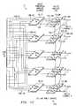
- FIGS. 1A-1Cform a schematic diagram showing an overview of the data paths through a router, in an embodiment of the present invention
- FIG. 2is a block diagram illustrating data flow through facility modules of a router in more detail
- FIG. 3is a block diagram illustrating information flow through a typical packet forwarding module
- FIG. 4is a block diagram representing information flow through a typical internal optics module, according to an embodiment of the present invention.
- FIGS. 5A and 5Bare schematic diagrams illustrating the functioning of a facility ASIC in the normal working mode and in the protection switch mode respectively;
- FIG. 6is a flow diagram outlining the steps involved in performing an automatic PFM protection switch, in accordance with an embodiment of the present invention.
- FIGS. 1A-1Cform a schematic diagram showing an overview of the data paths through a router 10 , in an embodiment of the present invention.
- FIGS. 1A-1Care partitioned into three sequentially adjacent panels.
- FIGS. 1A-1Cdo not show how router system 10 is wired, but simply illustrates the flow of data.
- an input 101 - 0is a first SONET data channel, formatted as Packet-over-SONET in the present embodiment.
- Input 101 - 0includes two optical fibers, namely a working input fiber 101 - 0 W and a protect input fiber 101 - 0 P.
- Fibers 101 - 0 W, 101 - 0 Pcarry duplicated information into router 10 from a peer source equipment e.g., another router or piece of SONET transmission equipment, compatible with the Packet-over-SONET format.
- Protect and working facility module cards 11 - 0 P and 11 - 0 Windependently receive duplicate input from respective optic fibers 101 - 0 P and 101 - 0 W and perform an integrity check on the information by computing SONET parity and SONET framing words to determine if the information is valid, and independently check SONET protection switching ‘K’ Bytes.
- Both facility modules 11 - 0 W and 11 - 0 Pperform essentially identical functions on the information.
- Each facility moduleindependently evaluates the SONET frame and determines whether the information contained on it is valid.
- Facility modules 11 - 0 W and 11 - 0 Pthen extract packets from their respective SONET frames and transfer those packets over a packet bus 103 to a packet forwarding module (PFM) 13 - 0 .
- Working facility module 11 - 0 W and protect facility module 11 - 0 Prespectively provide duplicate input interfaces 103 - 0 W and 103 - 0 P to packet forwarding module 13 - 0 .
- a system controller(not shown in FIGS. 1A-1C ) examines the status of facility modules 11 - 0 W and 11 - 0 P and selects as the in-service facility module the one that is receiving properly framed and bit-error-free packets on its input, in accordance with the SONET standard or as selected by SONET ‘K’ Bytes. Should the information coming into a facility module, for example facility module 11 - 0 P, have bit errors or other defects, then facility module 11 - 0 P raises an alarm at the system controller (not shown in FIGS.
- facility module 11 - 0 Wselects facility module 11 - 0 W as the source of input from that channel, and facility module 11 - 0 W strips the packets out of the SONET framing overhead and transfers those raw packets over industry standard bus 103 - 0 W to packet forwarding module 13 - 0 .
- facility modules 11 - 0 W and 11 - 0 P, along with packet forwarding module 13 - 0are contained in a line shelf, denoted in FIG. 1A as 1 ⁇ 2 line shelf 142 (ingress) and described below in more detail.
- N+1 multiple packet forwarding modules 13 - 0 through 13 -NThere are actually N+1 multiple packet forwarding modules 13 - 0 through 13 -N.
- Nequals 4, providing for four working packet forwarding modules 13 - 0 through 13 - 3 and a fifth designated protect packet forwarding module 13 - 4 .
- protect packet forwarding module 13 - 4is a spare module available to replace any working module 13 - 0 through 13 - 3 . Should any one of working packet forwarding modules 13 - 0 through 13 - 3 fail, d then fifth packet forwarding module 13 - 4 can substitute for the failed packet forwarding module 13 - 0 through 13 - 3 .
- This protection configurationis known as “one-for-four” protection.
- packet forwarding modules 18 - 0 through 18 - 3are all working modules, and packet forwarding module 18 - 4 is a spare protect packet forwarding module available as a replacement in the event of failure of any working packet forwarding module 18 - 0 through 18 - 3 .
- packet forwarding modules 18 - 0 through 18 - 4are contained in a line shelf, denoted in FIG. 1C as 1 ⁇ 2 line shelf 14 - 3 (egress) and described below in more detail.
- Protectionworks through a daisy-chain data bus 105 cascading from Channel 0 to Channel 1 , to Channel 2 , to Channel 3 , and to Channel 4 , linking facility modules 11 - 0 W through 11 - 4 W.
- a duplicate data businterconnects from Channel 4 up to Channel 0 , linking facility modules 11 - 4 P through 11 - 0 P. If for example packet forwarding module 13 - 1 were to fail, then input facility modules 11 -IP and 11 - 1 W send their traffic down data bus 105 linking facility modules 11 - 2 and 11 - 3 to facility module 11 - 4 , which then switches those inputs to protect packet forwarding module 13 - 4 .
- a microprocessor in the line shelf containing the failed packet forwarding moduledetects the failure, notices if the system is configured for one-for-four protection, and instructs switches on facility modules 11 - 1 through 11 - 4 to switch traffic that used to be in Channel 1 down to Channel 4 .
- Channel 4contains facility modules 11 - 4 P and 11 - 4 W on the input side and facility modules 12 - 4 P and 12 - 4 W on the output side respectively of router 10 . These modules are connected to optical inputs and outputs only when utilizing protect PFM 13 - 4 or 18 - 4 as a working module and not as protection for PFMs 13 - 0 through 13 - 3 or 18 - 0 through 18 - 3 .
- daisy chain bus 105 , 106is not utilized in any way, and there are simply 5 working inputs and 5 working outputs. Accordingly, two modes of operation are available; namely one-for-N protection, for example one-for-four; or zero-for-five protection, meaning no protect modules and five working modules. Without requiring any wiring changes, router system 10 will function in either mode.
- An alternative operating modedesignates input 101 -N and output 102 -N for lower priority traffic. That traffic would be deliberately interrupted in the event of a failure of any of the packet forwarding modules carrying higher priority traffic and requiring a protect packet forwarding module to service that failure.
- IOMsinternal optics modules
- PFM 13 - 0internal optics modules
- Packets contained in virtual out queues of PFM 13 - 0 that are destined for the same egress PFMcan be combined to form a single chunk payload of data.
- multiple small packets or just a segment of a larger packetcan be loaded into a single chunk.
- a maximum of two chunkscan be transferred from a PFM 13 - 0 to the IOMs 14 - 0 W 0 and 14 - 1 W 0 during each chunk period. The same chunks are replicated and transferred in parallel to IOMs 14 - 0 W 1 and 14 - 1 W 1 .
- IOM modules 14encapsulate FEC code words as multiple redundant check symbols into each of the chunks.
- the present implementationuses a conventional interleaved Reed-Solomon FEC coding.
- IO modules 14 - 0 W 0 , 14 - 1 W 0provide duplicate working module capacity for a working zero optical switch plane.
- IO modules 14 - 0 W 1 , 14 - 1 W 1provide duplicate working module capacity for a working one optical switch plane.
- Switch plane pairs in this caseare not configured as working and protect, but as working zero and working one copies respectively, such that copy zero switch plane containing optical switch modules 15 - 1 through 15 - 6 and duplicate copy one switch plane containing optical switch modules 16 - 1 through 16 - 6 each provide 6 optical switches worth of capacity.
- IO module 14 - 0 W 0transfers information from PFM 13 - 0 to one of three optical switch modules 15 - 1 , 15 - 2 and 15 - 3 .
- IO module 14 - 0 W 0sends the information to the appropriate optical switch module based on the decisions of the central arbiter module (not shown in the figures), described in U.S. application Ser. No. 09/703,057 cited above.
- one inputcomes into an optical switch module and one output goes out from that same optical switch module. In an actual system, these inputs and outputs in fact provide connectivity across router system 10 .
- optical switch module 15 - 1shows optical switch module 15 - 1 connected to an egress side internal optics module 17 - 0 W 0 through an output fiber 110 - 1 .
- six such optical switch modules 15 - 1 through 15 - 6are shown in the top portion of FIG. 1 B.
- each of these optical switch moduleshas 64 optical fibers in and 64 optical fibers out, with these 64 optical fiber pairs fanning out to a great many different line shelves. Different shelves have multiple fiber inputs and outputs.
- Six parallel optical switch modules 15 - 1 through 15 - 6provide 6 times the data capacity of a single switch module. Other embodiments can have for example, 36 of these modules rather than six.
- Chunks of informationare sent individually through optical switch modules 15 - 1 through 15 -N and 16 - 1 through 16 -N and received by IO modules 17 on line shelves at the egress side of router 10 .
- IO module 17checks the FEC check symbols to validate the accuracy of the data bits within the chunk. It then removes the FEC check symbols and transfers the resulting chunk payloads to packet forwarding module 18 - 0 , 18 - 1 , 18 - 2 , 18 - 3 , or 18 - 4 as appropriate for each destination address.
- the working one optical switch plane containing optical switch modules 16 - 1 through 16 -Ndoes substantially the same thing in parallel. Thus, working zero and working one optical switch planes perform this process duplicatively and in parallel.
- IO modules 17If there are only a few bit errors going through a switch, those errors can be corrected in real time by FEC decoding in IO modules 17 . If a path through a working zero optical switch fails completely, then a path through the working one optical plane can be utilized instead. Further, because each IO module 17 computes the corrupted bits and how many bits were corrected on every path of the system, IO modules 17 provide a detailed fault analysis not only of the failed fiber or optical switch plane, but even down to the level of an individual switch defect, which then can also be isolated. Importantly, the data flowing across for example OS Module 15 - 1 and the data flowing across OS Module 16 - 1 in the absence of failures in the system are identical, byte for byte. This provides a hot standby, chunk for chunk.
- packet forwarding modules 18 - 0 through 18 -Nthen reassemble the chunks into individual IP packets and forward those packets across interface links 104 , as previously described.
- corresponding input and output functionsare shown on separate circuit cards in separate 1 ⁇ 2 line shelves 142 and 143 respectively.
- corresponding input and output functionsare combined on a single circuit card in a single line shelf combining 1 ⁇ 2 line shelves 142 and 143 , thereby creating a folded configuration.
- working input facility module 11 - 0 W and working output facility module 12 - 0 Wcan be combined on a single physical printed circuit card with two optical connectors, one in and one out.
- protect input facility module 11 - 0 P and protect output facility module 12 - 0 Pcan be combined on a single physical circuit card with two optical connectors, one in and one out.
- input and output packet forwarding modules 13 - 0 and 18 - 0also can be combined on a single physical circuit card in a single line shelf.
- packet forwarding modules 13 - 0 and 18 - 0share the same physical card, then there is a single card for Channel 0 , likewise a single card each for Channels 1 , 2 , 3 , and a fifth card for a Protect channel 4 . Because there is a single physical card for input and output functions, then if a card fails, the protection ratio is equal for both input and output modules on that card.
- internal optics modules 14 - 0 W 0 and 17 - 0 W 0similarly share the same physical circuit card, which in the present implementation is contained in the same line shelf 142 , 143 with combined input/output facility modules 11 , 12 and combined input/output packet forwarding modules 13 , 18 .
- FIG. 2is a block diagram illustrating data flow through facility modules 11 - 0 W and. 12 - 0 W, for example, in more detail.
- Facility optical fibersare connected on the left through input and output interfaces 101 - 0 W and 102 - 0 W respectively.
- input and output facility modules 11 - 0 W and 12 - 0 Woccupy the same circuit board in the same line shelf in a folded configuration.
- the input and output facility modules 11 - 0 W and 12 - 0 Ware located on separate physical circuit cards.
- a signale.g., a packet-over-SONET (POS) formatted IP packet, arrives at input 101 - 0 W to a signal processing module 201 typically in a ten-Gbit/sec OC192 SONET datastream.
- Processing module 201contains an optical receiver, an optical multiplexer and associated demultiplexer, and a transmitter associated with those.
- the received signalis demodulated from optical input 101 - 0 W into an electronic signal, and then demultiplexed from a single ten-Gbit-per-second datastream in this example down to a parallel bus at a lower data speed. That parallel bus of signals then leaves module 201 and goes into a processing module 202 .
- Module 202contains an OC192 demultiplexer, which extracts a single 2.5 Gbit/second OC48 substream out of the OC192 stream and delivers a packet-over-SONET (POS) input to a framer 203 - 1 , which is an industry standard off the shelf component. Likewise, module 202 extracts the other three OC48 substreams and sends these to POS framers 203 - 2 , 203 - 3 , and 203 - 4 respectively. At this point there are four parallel 2.5 Gbit/sec SONET streams, one to each of four POS framers 203 - 1 through 203 - 4 , which extract from each OC48 stream the individual IP packets.
- POSpacket-over-SONET
- POS framers 203 - 1 through 203 - 4first have to find the IP packets in the datastream and then have to extract the packets from the SONET continuous datastream. This is done on the four parallel OC48 streams. Once it has removed the packets from the SONET frame, each POS framer 203 - 1 through 203 - 4 delivers those packets to a facility ASIC 204 - 1 through 204 - 4 respectively.
- facility ASICs 204 - 1 through 204 - 4The principal function of facility ASICs 204 - 1 through 204 - 4 is to send that information to an appropriate packet forwarding module (not shown in FIG. 2 ), in this case through an interface 103 - 0 W consisting of four parallel interfaces for the four packet streams, or, if directed, to receive packets from an upstream neighboring facility ASIC on an interface 103 - 4 W and switch 103 - 4 W to 103 - 0 W in a protect mode. Otherwise, in a working mode of operation, a facility ASIC sends the information out through interface 103 - 0 W, and information input on 103 - 4 W is directed through cascading protection bus interface 105 - 0 W.
- the normal sequenceis for a facility ASIC to take information from above and switch it below, letting the received traffic pass straight through onto interface 103 - 0 W. All four of facility ASIC switches 204 - 1 through 204 - 4 are ganged, such that they operate in parallel. With faster buses, faster framers, or faster facility ASICs, a single ASIC or bus, for example, could perform the above described functions instead of four required at the present state of technology.
- FIGS. 5A and 5Bare schematic diagrams illustrating the functioning of a facility ASIC 204 - 1 in the normal working mode and in the protection switch mode respectively. If there is no failed packet forwarding module (PFM), then a facility ASIC 204 - 1 is configured as shown in FIG. 5A , which illustrates protection switching in a single direction. In this case, a received signal on input interface 210 is sent through to output 213 , whereas the input protection bus 103 - 4 W is connected to the output protection bus 105 - 0 W. If a failure of an associated packet forwarding module is detected, a microprocessor (not shown) instructs facility ASIC 204 - 1 to go into the protection switch mode, illustrated in FIG. 5 B.
- PFMpacket forwarding module
- a signal from input 210 instead of going to output 213is switched to output protection bus 105 - 0 W, input protection bus 103 - 4 W is open and there is no signal available at output 213 .
- This protection processin essence switches input 210 either to output 213 or down through output protection bus 105 - 0 W, depending on whether facility ASIC 204 - 1 has been instructed to execute a protection switch.
- the inverse directions going up the facility ASIC chain and out from the packet forwarding modulesare essentially the reverse of FIGS. 5A and 5B .
- Information traveling the reverse directionthat is from router 10 outbound on facility interface 102 - 0 W, arrives from packet forwarding module 18 - 0 on interface 104 - 0 W.
- the informationgoes directly through to facility module 12 - 0 W, following the inverse of FIG. 5 A.
- the protection switch modethe information is diverted through protection bus 106 - 0 W.
- ASIC 204 - 1directs the information packets through output link 211 to Packet-over-SONET framer 203 - 1 , which receives a packet, inserts it into a SONET frame, producing a 2.5 gigabit/second datastream or parallel bus equivalent, and sends that frame to OC 192 add/drop multiplexer 202 .
- Multiplexer 202combines four 2.5 gigabit/second streams from POS framers 203 - 1 through 2034 , multiplexes them together into a 10 gigabit/second datastream, and delivers them to optical transceiver 201 .
- Transceiver 201receives the 10 gigabit/second stream, which is formatted as a parallel bus, and multiplexes it into a single datastream, which modulates a laser diode. This produces a SONET ten-gigabit/second optical format, which is transmitted through outbound optical facility interface link 102 - 0 W.
- FIG. 3is a block diagram illustrating information flow through a typical packet forwarding module 13 - 0 ( 18 - 0 ).
- Facility ASICs 301 - 1 through 301 - 4 on the ingress sidereceive packets from facility modules working and protect 11 - 0 W and 11 - 0 P through single links 103 - 0 W 0 through 103 - 0 W 3 .
- a principal function of facility ASICs 301 - 1 through 301 - 4 on the ingress sideis to select between the working and the protection facility modules, as represented by the information on, for example, incoming path 103 - 0 W 0 or 103 - 0 P 0 .
- That selectionis made based on the standard SONET criteria for defining if one or both of those incoming facility modules is flawed or failed and also based on any detection of local errors or failures on working facility module 11 - 0 W or protect facility module 11 - 0 P.
- a principal function of facility ASICs 301 - 1 through 301 - 4is to duplicate the packet stream coming out of egress ASIC 302 and to send that packet stream out across both outgoing paths 104 - 0 W 0 and 104 - 0 P 0 to facility modules 12 - 0 W and 12 - 0 P (see FIG. 2 ).
- Packet forwarding engines 306 - 1 through 306 - 4are devices that inspect the packet headers of all of the incoming packets received on any of the selected working or protect facility modules that are associated with this particular packet forwarding module 13 - 0 ( 18 - 0 ). Based on the inspection of those headers, a determination of the intended destination of each packet can be made.
- the header informationis stored by an ingress ASIC 304 in various queues and lists, which are used to determine for any given packet which output port of the router it should exit, when it should exit, and its relative priority. Actual packet data is stored by ingress ASIC 304 in an external RAM memory 305 .
- Packet forwarding engine 306 - 1 through 306 - 4also determines if any particular packet is intended for a local destination within this particular router and redirects it toward the main control processor of the router instead of transmitting it downstream out one of the output ports of the router to a peer router across the network.
- Ingress ASIC 304based on the states of the various queues that it maintains and based on the destination addresses of the various packets that are represented by headers in those queues, sends requests through optical transceiver units 308 -W and 308 -P across optical link 310 (typically multimode ribbon fiber) to the central arbiter (not shown in FIG. 3 ).
- the central arbiterdetermines, based on all of the packets that are being processed through the router in aggregate at any given time, which of the requests from a particular ingress ASIC should be granted and when it should be granted for transmission across the optical switch. Grants of those requests return across optical link 310 through transceivers 308 -W and 308 -P back to ingress ASIC 304 .
- Ingress ASIC 304uses that grant information to extract packets from memory 305 in the appropriate order and assembles them into chunk payloads. At the appropriate times ingress ASIC 304 sends those chunk payloads across channels 107 - 00 through 107 - 03 to internal optics modules 14 - 0 W 0 through 14 -NW 1 (see FIG. 1 B).
- information chunk payloadsare received from the optical switch matrix indirectly through internal optics modules 17 - 0 W 0 through 17 -NW 1 (sec FIG. 1B ) across links 108 - 00 through 108 - 03 into an egress ASIC 302 .
- Egress ASIC 302reconfigures the chunks into packets and again stores the packets in a memory 303 in the form of queues and structures.
- Egress ASIC 302subsequently reads those packets out again into one of the four facility ASICs 301 - 1 through 301 - 4 .
- each of those packet streamsis duplicated and sent in tandem to both working and protect facility modules 12 - 0 W and 12 - 0 P.
- a line control processor 307is primarily responsible for controlling the facility protection switching function by examining the SONET error and failure indications from facility modules 11 - 0 W and 11 - 0 P and also by analyzing the indications that facility ASICs 301 - 1 through 301 - 4 develop from those incoming signals. The appropriate switching decisions are made in software and logic and are then implemented by line control processor 307 .
- FIG. 4is a block diagram representing information flow through a typical internal optics module 14 ( 17 ), according to an embodiment of the present invention.
- Internal optics module 14receives chunk payloads of data via input links 107 - 00 through 107 - 04 from packet forwarding modules 13 - 0 through 13 -N (see FIG. 3 ).
- An internal optics ASIC 407selects chunk payloads from those inputs based on grant information that comes back from the central arbiter through each packet forwarding module 13 - 0 through 13 -N.
- Internal optics ASIC 407selects which inputs 107 - 00 through 107 - 04 will be passed at any point in time to three MUXs 401 - 1 through 401 - 3 and out through three 12.5-gigabit-per-second transmitters 403 - 1 through 403 - 3 toward the optical switch modules over single mode optical fiber links 109 - 1 through 109 - 3 .
- Internal optics ASIC 407is responsible for encapsulating the chunk payloads with the forward error correcting (FEC) headers and check sums that guarantee that the chunks pass across the optical switch without error, or that if errors occur, they are either corrected or detected.
- FECforward error correcting
- optical signals coming in over multimode optical fiber links 110 - 1 through 110 - 3pass through 12.5-gigabit-per-second receivers 404 - 1 through 404 - 3 and into three DEMUXs 402 - 1 through 402 - 3 .
- Receivers 404 - 1 through 404 - 3convert the data chunks from optical to electrical bits and DEMUXs 402 - 1 through 402 - 3 convert these from a serial bit stream to lower bit rate parallel bit streams.
- Internal optics ASIC 407compares the calculated FEC (forward error correction) check sums with the encoded check sums and determines if any errors have occurred across the switch matrix, corrects those errors if possible, and if not, provides alarm and performance monitoring information based on those errors. Internal optics ASIC 407 then strips away the FEC coding from the chunks and passes the resulting chunk payloads from the demux channels out through links 108 - 00 through 108 - 04 to packet forwarding modules 18 - 0 through 18 -N.
- FECforward error correction
- chunk payloads received from internal optics modules 17are broken down into their original packets by egress ASIC 302 (see FIG. 3 ).
- the packetsare stored in memory 303 and are then retrieved and delivered at the appropriate time to facility modules 12 - 0 W and 12 - 0 P.
- Each packet forwarding module 13packages chunk payloads as described earlier and sends identical streams of chunk payloads to both working 1 and working 0 copies of the optical fabric via internal optics modules (IOMs) 14 - 0 W 0 through 14 -NW 1 (see FIG. 1 B).
- IOMsinternal optics modules
- Working 0 copy of the optical switch fabricincludes internal optics modules 14 - 0 W 0 and 14 - 1 W 0 , optical switch modules 15 - 1 through 15 - 6 , and internal optics modules 17 - 0 W 0 and 17 - 1 W 0
- working 1 copy of the optical switch fabricincludes internal optics modules 14 - 0 W 1 and 14 - 1 W 1 , optical switch modules 16 - 1 through 16 - 6 , and internal optics modules 17 - 0 W 1 and 17 - 1 W 1
- IOM 14 - 0 W 0 and IOM 14 - 0 W 1each receive simultaneous sequences of chunk payloads from each packet forwarding module 13 that is transmitting through those two IOMs.
- each packet forwarding module items 18 - 0 through 18 -Nreceives a simultaneous sequence of chunk payloads from IOMs 17 - 0 W 0 and 17 - 0 W 1 , for example.
- the simultaneous sequences of chunk data delivered to each packet forwarding moduleare identical.
- the affected IOMis able to detect that failure based on comparison of the received FEC check sums with the calculated FEC check sums.
- the IOMWhen a failure on a particular chunk from either working zero or working one copy of the optical switch fabric is detected, the IOM inserts a failure indication downstream toward PFMs 18 . This forces PFM 18 to select the error-free chunk data from the alternate copy of the optical switch fabric. This can be done individually for each chunk payload delivered to a particular PFM.
- internal optics ASIC 407detects any errors or failures of a given chunk on either copy zero or copy one of the switch fabric and inserts appropriate failure indications downstream toward all of the packet forwarding modules connected to it.
- egress ASIC 302receives those failure indications and selects on a chunk by chunk basis between either the copy zero or the copy one switch fabric. Only error-free chunk payloads from an unfailed switch fabric are inserted into memory and subsequently retrieved and broken out into packets, which are then transmitted toward facility modules 12 - 0 W and 12 - 0 P.
- FIG. 6is a flow diagram outlining the steps involved in performing an automatic PFM protection switch, in accordance with an embodiment of the present invention.
- the various associated apparatus modulesare described above in connection with FIGS. 1A-1C , 2 , 3 , and 4 .
- a PFM faultis detected by a line shelf control module (LSCM), described in U.S. application Ser. No. 09/703,057, cited above, which is interconnected through a control network (CNET) with LCP 307 in PFM 13 (see FIG. 3 ).
- LSCMline shelf control module
- CNETcontrol network
- step 602 athe LSCM localizes and analyzes the PFM fault.
- the faultis assumed to occur in PFM 13 - 2 ( 18 - 2 ) and the protect PFM is assumed to be PFM 13 - 4 ( 18 - 4 ).
- protect PFM 13 - 4is operating in an “extra traffic” mode, such that it is carrying preemptable low priority traffic prior to the protection switch. This mode requires the most complex protection switch steps, which are sufficient to handle all other PFM protection switch cases.
- a similarly complex modeis the case in which the protect PFM is already protecting a working PFM when a higher priority working PFM fails. In the latter case, the protect PFM is already carrying data through the system and must be reconfigured for a different working PFM.
- step 602 bthe LSCM makes a protect decision.
- the LSCMmanages the PFM protection switch process.
- step 603packet forwarding engines 306 on protect PFM 13 - 4 ( 18 - 4 ) are configured to stop sending packets to ingress ASIC 304 - 4 .
- Thisallows ingress ASIC 304 - 4 to empty its queues of all the currently buffered packets. If ingress ASIC 304 - 4 has a built-in way to reset its memory queues, then this step will also be performed on protect PFM 13 - 4 ( 18 - 4 ).
- This stepwill also prevent peer router messages (incoming from the facility interfaces) from being sent to the master control processor (MCP) for protect PFM 134 ( 18 - 4 ).
- MCPmaster control processor
- packet forwarding engines 306 on protect PFM 13 - 4 ( 18 - 4 )are still able to generate administrative packets to communicate with the MCP, and flow control information can still be sent. This squelch operation could also be done at facility ASIC 301 on protect PFM 13 - 4 ( 18 - 4 ).
- egress IOMs 17are remapped to prevent any traffic addressed specifically for protect PFM 13 - 4 ( 18 - 4 ) from being received. This traffic is typically discarded. This is accomplished by disabling the output port on egress IOMs 17 connecting through lines 108 to egress ASIC 302 - 4 on protect PFM 13 - 4 ( 18 - 4 ).
- step 605if egress ASIC 302 - 4 has a built-in way to reset its memory queues, then this step will also be performed on protect PFM 13 - 4 ( 18 - 4 ).
- step 606flow control for protect PFM 13 - 4 ( 18 - 4 ) is cleared. This allows any module configured to send input to protect PFM 13 - 4 ( 18 - 4 ) to empty any buffers that may have been in a flow control “holding pattern.” This is be accomplished by forcing a clear of flow control for all queues in egress ASIC 302 - 4 of protect PFM 13 - 4 ( 18 - 4 ). The updated flow control information is then distributed to the system through the normal flow control paths.
- step 607all traffic associated with the facility modules 11 - 4 W, 11 - 4 P ( 12 - 4 W, 12 - 4 P) connected to protect PFM 13 - 4 ( 18 - 4 ) is blocked.
- This squelchingis accomplished by protect PFM LCP 307 - 4 informing POS framers 203 to insert path alarm indication signals (AIS).
- AISpath alarm indication signals
- This stepcan be omitted if no facility modules capable of interfacing with customers are associated with the protect PFM. Importantly, this action will prevent misconnects of packets to the wrong ports, which otherwise allow data to go out into the network through the facility modules associated with the protect PFM.
- step 608the ingress input and egress output on IOMs 14 ( 17 ) are disabled that lead to protected PFM 13 - 2 ( 18 - 2 ). Inputs to protected PFM 13 - 2 ( 18 - 2 ) from FMs are blocked. This prevents protected PFM 13 - 2 ( 18 - 2 ) from using system resources when it either has not failed or has failed uncontrollably. Shutting down the inputs to protected PFM 13 - 2 ( 18 - 2 ) allows the ingress and egress ASICs to clear their memory buffers.
- step 609the specific routing tables of protected PFM 13 - 2 ( 18 - 2 ) are loaded into protect PFM 13 - 4 ( 18 - 4 ), along with any software state information, for example the current working/protect selection of facility modules for protected PFM 13 - 2 ( 18 - 2 ), and weighted random early discard (WRED) provisioning, a TCP protocol packet discard policy that reduces congestion.
- WREDweighted random early discard
- Step 610re-enables packet forwarding engines 306 in protect PFM 134 ( 18 - 4 ) to resume forwarding packets, although only idle packets should be received at this time. In other words, even though packet forwarding engines 306 are able to forward packets, they are not receiving any packets to forward, because IOMs 14 ( 17 ) and associated FMs still have their outputs blocked.
- Step 611changes the identity of egress ASICs 302 - 4 on protect PFM 13 - 4 ( 18 - 4 ) to virtualize protected PFM 13 - 2 ( 18 - 2 ). Also the flow control override in egress ASIC 302 - 4 is reversed to re-enable normal flow control operation using the new identity.
- step 612the LSCM using the CNET informs the arbitration shelf control module (ASCM) of the PFM protection action, allowing the ASCM to configure the appropriate arbiter interface module (AIM) to route peer communication from the MCP to the appropriate PFM.
- ASCMarbitration shelf control module
- AIMarbiter interface module
- This message received at the ASCMalso configures the AIMs to clear the flow control settings for the unavailable port(s) (in this case protect PFM 13 - 4 ) and resend to all the PFMs in the system.
- the LSCMalso informs the MCP that the physical ports associated with protect PFM 134 ( 18 - 4 ) are now unavailable.
- the MCPinforms the entire system with a system table update that these ports are unavailable.
- step 613the FMs are mapped as controlled by the LSCM to route the traffic and to signal protect PFM 13 - 4 ( 18 - 4 ) to route remote processor interface (RPI) control to the FMs from protect PFM 13 - 4 ( 184 ) through the appropriate daisy chain bus 105 ( 106 ) using facility ASICs 204 (see FIGS. 2 and 5 A- 5 B).
- RPIremote processor interface
- egress IOMs 17are mapped to allow the received egress traffic normally directed to protected PFM 13 - 2 ( 18 - 2 ) to go to protect PFM 13 - 4 ( 18 - 4 ). This allows egress ASIC 3024 to start receiving the correct traffic on protect PFM 13 - 4 ( 18 - 4 ), thus completing the protection switch at block 615 .
- the steps to reverse the PFM protection switchare similar to the switch steps and are not detailed here. Of importance when reversing of PFM protection switch is to delay enabling the protect “extra traffic” until the working traffic is routed to the appropriate set of facility modules, to avoid misconnecting the data to the wrong ports.
- each packet forwarding module 13packages chunk payloads as described earlier and sends identical streams of chunk payloads to both working 1 and working 0 copies of the optical switch fabric via internal optics modules (IOMs) 14 - 0 W 0 through 14 -NW 1 (see FIG. 1 B), which encapsulates the chunk payloads into chunks.
- IOMsinternal optics modules
- Working 0 copy of the optical switch fabricsee FIG. 1
- IOM 14 - 0 W 0 and IOM 14 - 0 W 1each receive simultaneous sequences of chunk payloads from each packet forwarding module 13 that is transmitting through those two IOMs.
- each packet forwarding module 18 - 0 through 18 -Nreceives a simultaneous sequence of 1 chunk payloads from IOMs 17 - 0 W 0 and 17 - 0 W 1 , for example.
- the simultaneous sequences of chunk data delivered to each packet forwarding moduleare identical.
- the affected IOMis able to detect that failure based on comparison of the received FEC check sums with the calculated FEC check sums.
- the IOMWhen a failure on a particular chunk from either working zero or working one copy of the optical switch fabric is detected, the IOM inserts a failure indication downstream toward PFMs 18 . This forces PFM 18 to select the error-free chunk data from the alternate copy of the optical switch fabric. This can be done individually for each chunk payload delivered to a particular PFM.
- Embodiments according to the present inventionare designed to protect against all single fault occurrences.
- Single faultsinclude a single fault of a module, a single fault of a cable, or a single fault of a path. Accordingly, although some double faults are protected against, double faults generally lie beyond the scope of principal objects of the present invention and thus are not in general protected against.
Landscapes
- Engineering & Computer Science (AREA)
- Computer Networks & Wireless Communication (AREA)
- Signal Processing (AREA)
- Computer Security & Cryptography (AREA)
- Data Exchanges In Wide-Area Networks (AREA)
Abstract
Description
Claims (33)
Priority Applications (2)
| Application Number | Priority Date | Filing Date | Title |
|---|---|---|---|
| US09/703,043US6879559B1 (en) | 2000-10-31 | 2000-10-31 | Router line card protection using one-for-N redundancy |
| EP01309201AEP1202504A3 (en) | 2000-10-31 | 2001-10-30 | Router line card protection using One-for-N redundancy |
Applications Claiming Priority (1)
| Application Number | Priority Date | Filing Date | Title |
|---|---|---|---|
| US09/703,043US6879559B1 (en) | 2000-10-31 | 2000-10-31 | Router line card protection using one-for-N redundancy |
Publications (1)
| Publication Number | Publication Date |
|---|---|
| US6879559B1true US6879559B1 (en) | 2005-04-12 |
Family
ID=24823727
Family Applications (1)
| Application Number | Title | Priority Date | Filing Date |
|---|---|---|---|
| US09/703,043Expired - Fee RelatedUS6879559B1 (en) | 2000-10-31 | 2000-10-31 | Router line card protection using one-for-N redundancy |
Country Status (2)
| Country | Link |
|---|---|
| US (1) | US6879559B1 (en) |
| EP (1) | EP1202504A3 (en) |
Cited By (73)
| Publication number | Priority date | Publication date | Assignee | Title |
|---|---|---|---|---|
| US20020112085A1 (en)* | 2000-12-21 | 2002-08-15 | Berg Mitchell T. | Method and system for communicating an information packet through multiple networks |
| US20020116475A1 (en)* | 2000-12-21 | 2002-08-22 | Berg Mitchell T. | Method and system for communicating a request packet in response to a state |
| US20030021226A1 (en)* | 2001-07-24 | 2003-01-30 | Gal Mor | Interconnect and gateway protection in bidirectional ring networks |
| US20030041208A1 (en)* | 2001-07-27 | 2003-02-27 | Alcatel | Network element with redundant switching matrix |
| US20030091165A1 (en)* | 2001-10-15 | 2003-05-15 | Bearden Mark J. | Report generation and visualization systems and methods and their use in testing frameworks for determining suitability of a network for target applications |
| US20030097438A1 (en)* | 2001-10-15 | 2003-05-22 | Bearden Mark J. | Network topology discovery systems and methods and their use in testing frameworks for determining suitability of a network for target applications |
| US20030133405A1 (en)* | 2002-01-15 | 2003-07-17 | Evolium S.A.S. | Method and apparatus for healing of failures for chained boards with SDH interfaces |
| US20030137980A1 (en)* | 2002-01-21 | 2003-07-24 | Chung-Ji Jung | Router system and method of duplicating forwarding engine |
| US20030137934A1 (en)* | 2002-01-24 | 2003-07-24 | William Schaller | System and method for providing management of fabric links for a network element |
| US20030188216A1 (en)* | 2001-10-01 | 2003-10-02 | International Business Machines Corporation | Controlling the state of duplexing of coupling facility structures |
| US20040078620A1 (en)* | 2002-08-02 | 2004-04-22 | Corrigent Systems Ltd. | Equipment protection using a partial star architecture |
| US20040133619A1 (en)* | 2003-01-07 | 2004-07-08 | Corrigent Systems Ltd. | Hierarchical virtual private lan service protection scheme |
| US20050094553A1 (en)* | 2003-11-03 | 2005-05-05 | Cisco Technology, Inc. | Combined electro-mechanical and solid state switching fabric |
| US20050169284A1 (en)* | 2004-01-30 | 2005-08-04 | Srikanth Natarajan | Method and system for managing a network having an HSRP group |
| US20050169281A1 (en)* | 2004-02-02 | 2005-08-04 | Eun-Sook Ko | Distributed router |
| US20050213561A1 (en)* | 2001-10-26 | 2005-09-29 | Maxxan Systems, Inc. | System, apparatus and method for address forwarding for a computer network |
| US20050243710A1 (en)* | 2002-06-21 | 2005-11-03 | Christensen Carl L | Fault-tolerant broadcast router |
| US6999408B1 (en)* | 1998-06-18 | 2006-02-14 | Cisco Technology, Inc. | Failure tolerant high density dial router |
| US20060056303A1 (en)* | 2004-09-14 | 2006-03-16 | Aggarwal Amit K | Increased availability on routers through detection of data path failures and subsequent recovery |
| US20060062233A1 (en)* | 2000-12-19 | 2006-03-23 | Chiaro Networks Ltd. | System and method for router queue and congestion management |
| US20060109802A1 (en)* | 2004-11-19 | 2006-05-25 | Corrigent Systems Ltd. | Virtual private LAN service over ring networks |
| US20060117126A1 (en)* | 2001-07-30 | 2006-06-01 | Cisco Technology, Inc. | Processing unit for efficiently determining a packet's destination in a packet-switched network |
| US7058011B1 (en)* | 2001-02-26 | 2006-06-06 | Calix Networks, Inc. | N to one and one to one equipment protection switching |
| US7061859B2 (en) | 2001-08-30 | 2006-06-13 | Corrigent Systems Ltd. | Fast protection in ring topologies |
| US7065038B1 (en)* | 2001-02-28 | 2006-06-20 | Cisco Technology, Inc. | Automatic protection switching line card redundancy within an intermediate network node |
| US20070061418A1 (en)* | 2000-12-21 | 2007-03-15 | Berg Mitchell T | Method and system for initiating execution of software in response to a state |
| US20070165518A1 (en)* | 2006-01-18 | 2007-07-19 | Corrigent Systems Ltd. | VPLS failure protection in ring networks |
| US20070206618A1 (en)* | 2006-03-02 | 2007-09-06 | Corrigent Systems Ltd. | High capacity ring communication network |
| US20070211742A1 (en)* | 2006-01-30 | 2007-09-13 | Infinera Corporation | Application of hardware-based mailboxes in network transceivers and distributed approach for predictable software-based protection switching |
| US7286532B1 (en)* | 2001-02-22 | 2007-10-23 | Cisco Technology, Inc. | High performance interface logic architecture of an intermediate network node |
| US7289513B1 (en)* | 2001-06-15 | 2007-10-30 | Cisco Technology, Inc. | Switching fabric port mapping in large scale redundant switches |
| US7296093B1 (en) | 2001-12-31 | 2007-11-13 | Ciphermax, Inc. | Network processor interface system |
| US7295561B1 (en) | 2002-04-05 | 2007-11-13 | Ciphermax, Inc. | Fibre channel implementation using network processors |
| US20070268915A1 (en)* | 2006-05-19 | 2007-11-22 | Corrigent Systems Ltd. | Mac address learning in a distributed bridge |
| US7307995B1 (en) | 2002-04-05 | 2007-12-11 | Ciphermax, Inc. | System and method for linking a plurality of network switches |
| US20080068986A1 (en)* | 2002-10-17 | 2008-03-20 | Maranhao Marcus A | Method and system for optimized switchover of redundant forwarding engines |
| US20080075082A1 (en)* | 2006-09-22 | 2008-03-27 | Corrigent Systems Ltd. | Fault-tolerant medium access control (mac) address assignment in network elements |
| CN100382526C (en)* | 2005-09-08 | 2008-04-16 | 华为技术有限公司 | Active and standby method between interface cards in access network system |
| US7379970B1 (en) | 2002-04-05 | 2008-05-27 | Ciphermax, Inc. | Method and system for reduced distributed event handling in a network environment |
| US7382787B1 (en) | 2001-07-30 | 2008-06-03 | Cisco Technology, Inc. | Packet routing and switching device |
| US20080175262A1 (en)* | 2007-01-19 | 2008-07-24 | Fujitsu Limited | Data communication apparatus, configuration information update method, and configuration information update program |
| US7406038B1 (en)* | 2002-04-05 | 2008-07-29 | Ciphermax, Incorporated | System and method for expansion of computer network switching system without disruption thereof |
| US7421505B2 (en) | 2000-12-21 | 2008-09-02 | Noatak Software Llc | Method and system for executing protocol stack instructions to form a packet for causing a computing device to perform an operation |
| US20080225859A1 (en)* | 1999-01-12 | 2008-09-18 | Mcdata Corporation | Method for scoring queued frames for selective transmission through a switch |
| US7450438B1 (en) | 2002-06-20 | 2008-11-11 | Cisco Technology, Inc. | Crossbar apparatus for a forwarding table memory in a router |
| US20080279095A1 (en)* | 2007-05-11 | 2008-11-13 | Gallegos Joseph A | Redundant router and related methods |
| US7492705B1 (en)* | 2005-06-16 | 2009-02-17 | Embarq Holdings Company, Llc | Changing line cards associated with a communications network |
| US7512686B2 (en) | 2000-12-21 | 2009-03-31 | Berg Mitchell T | Method and system for establishing a data structure of a connection with a client |
| US7525904B1 (en)* | 2002-06-20 | 2009-04-28 | Cisco Technology, Inc. | Redundant packet routing and switching device and method |
| US7536476B1 (en) | 2002-12-20 | 2009-05-19 | Cisco Technology, Inc. | Method for performing tree based ACL lookups |
| US7640298B2 (en) | 2000-12-21 | 2009-12-29 | Berg Mitchell T | Method and system for communicating an information packet through multiple router devices |
| US7660303B2 (en) | 2006-08-22 | 2010-02-09 | Corrigent Systems Ltd. | Point-to-multipoint functionality in a bridged network |
| US7710991B1 (en) | 2002-06-20 | 2010-05-04 | Cisco Technology, Inc. | Scalable packet routing and switching device and method |
| US20100274907A1 (en)* | 2009-04-22 | 2010-10-28 | Fujitsu Limited | Communication apparatus for transmitting data through a plurality of data-paths |
| US7889712B2 (en) | 2004-12-23 | 2011-02-15 | Cisco Technology, Inc. | Methods and apparatus for providing loop free routing tables |
| US7940648B1 (en)* | 2004-03-02 | 2011-05-10 | Cisco Technology, Inc. | Hierarchical protection switching framework |
| US20110222394A1 (en)* | 2010-03-11 | 2011-09-15 | Ciena Corporation | Fabric extra traffic |
| US8205076B1 (en) | 2008-10-15 | 2012-06-19 | Adobe Systems Incorporated | Imparting real-time priority-based network communications in an encrypted communication session |
| US8285867B1 (en) | 2003-02-13 | 2012-10-09 | Adobe Systems Incorporated | Real-time priority-based media communication |
| US9026848B2 (en) | 2010-07-23 | 2015-05-05 | Brocade Communications Systems, Inc. | Achieving ultra-high availability using a single CPU |
| US9094221B2 (en) | 2010-03-19 | 2015-07-28 | Brocade Communications Systems, Inc. | Synchronizing multicast information for linecards |
| US9104619B2 (en) | 2010-07-23 | 2015-08-11 | Brocade Communications Systems, Inc. | Persisting data across warm boots |
| US9143335B2 (en) | 2011-09-16 | 2015-09-22 | Brocade Communications Systems, Inc. | Multicast route cache system |
| US9203690B2 (en) | 2012-09-24 | 2015-12-01 | Brocade Communications Systems, Inc. | Role based multicast messaging infrastructure |
| US9210105B2 (en) | 2012-04-27 | 2015-12-08 | Metaswitch Networks Ltd | Telecommunications equipment |
| US9274851B2 (en) | 2009-11-25 | 2016-03-01 | Brocade Communications Systems, Inc. | Core-trunking across cores on physically separated processors allocated to a virtual machine based on configuration information including context information for virtual machines |
| US9619349B2 (en) | 2014-10-14 | 2017-04-11 | Brocade Communications Systems, Inc. | Biasing active-standby determination |
| US9729594B2 (en) | 2000-09-12 | 2017-08-08 | Wag Acquisition, L.L.C. | Streaming media delivery system |
| US9967106B2 (en) | 2012-09-24 | 2018-05-08 | Brocade Communications Systems LLC | Role based multicast messaging infrastructure |
| US10063336B1 (en)* | 2017-10-24 | 2018-08-28 | Ciena Corporation | Protected transponded services integrated with control plane switched services |
| US10581763B2 (en) | 2012-09-21 | 2020-03-03 | Avago Technologies International Sales Pte. Limited | High availability application messaging layer |
| US10771150B2 (en)* | 2018-10-16 | 2020-09-08 | Fujitsu Limited | Parallel processing apparatus and replacing method of failing optical transmission line |
| US11323178B1 (en)* | 2021-01-19 | 2022-05-03 | Charter Communications Operating, Llc | Transport control based on layer 1 channel characteristics |
Families Citing this family (5)
| Publication number | Priority date | Publication date | Assignee | Title |
|---|---|---|---|---|
| US7139928B1 (en) | 2002-10-17 | 2006-11-21 | Cisco Technology, Inc. | Method and system for providing redundancy within a network element |
| FI122292B (en) | 2002-10-24 | 2011-11-15 | Tellabs Oy | Method, apparatus and network elements for performing transmission |
| CA2502711C (en)* | 2003-01-13 | 2011-03-15 | Cisco Technology, Inc. | Method and system for optimized switchover of redundant forwarding engines |
| EP1720298A1 (en)* | 2005-05-03 | 2006-11-08 | Alcatel | System comprising an aggregation sub-system and tributary sub-systems |
| US8850062B2 (en) | 2010-08-09 | 2014-09-30 | Cisco Technology, Inc. | Distributed connectivity verification protocol redundancy |
Citations (19)
| Publication number | Priority date | Publication date | Assignee | Title |
|---|---|---|---|---|
| US4160127A (en)* | 1978-06-27 | 1979-07-03 | Bell Telephone Laboratories, Incorporated | Time-slot interchange with protection switching |
| US4579079A (en)* | 1983-11-28 | 1986-04-01 | Northern Telecom Limited | Apparatus for use in coating an elongate filament |
| US4658396A (en)* | 1985-03-11 | 1987-04-14 | Barden Robert A | Redundancy arrangement for a local area network |
| US5014261A (en)* | 1986-01-07 | 1991-05-07 | Fujitsu Limited | System for switching from working units to stand-by units |
| US5583859A (en)* | 1994-08-30 | 1996-12-10 | Bell Communications Research, Inc. | Data labeling technique for high performance protocol processing |
| US5596569A (en) | 1994-03-08 | 1997-01-21 | Excel, Inc. | Telecommunications switch with improved redundancy |
| US5740157A (en)* | 1992-05-21 | 1998-04-14 | Alcatel Network Systems, Inc. | Distributed control methodology and mechanism for implementing automatic protection switching |
| US5831970A (en)* | 1996-12-13 | 1998-11-03 | Fujitsu Limited | Transmission apparatus |
| US5923643A (en) | 1997-02-27 | 1999-07-13 | Excel, Inc. | Redundancy, expanded switching capacity and fault isolation arrangements for expandable telecommunications system |
| US5937169A (en)* | 1997-10-29 | 1999-08-10 | 3Com Corporation | Offload of TCP segmentation to a smart adapter |
| US6151318A (en)* | 1998-07-06 | 2000-11-21 | Motorola, Inc. | Method and apparatus for encapsulating ATM cells in a broadband network |
| US6298038B1 (en)* | 1997-04-24 | 2001-10-02 | Nortel Networks Limited | Transparent transport |
| US6324162B1 (en)* | 1998-06-03 | 2001-11-27 | At&T Corp. | Path-based restoration mesh networks |
| US6332198B1 (en) | 2000-05-20 | 2001-12-18 | Equipe Communications Corporation | Network device for supporting multiple redundancy schemes |
| US6377543B1 (en)* | 1997-08-13 | 2002-04-23 | Telecommunications Research Laboratories | Path restoration of networks |
| US6445717B1 (en)* | 1998-05-01 | 2002-09-03 | Niwot Networks, Inc. | System for recovering lost information in a data stream |
| US6473397B1 (en)* | 1999-08-10 | 2002-10-29 | Nortel Networks Limited | Add/drop multiplexer and method, and Bi-directional line switcher ring featuring such multiplexers |
| US6587470B1 (en)* | 1999-03-22 | 2003-07-01 | Cisco Technology, Inc. | Flexible cross-connect with data plane |
| US6597826B1 (en)* | 1999-11-02 | 2003-07-22 | Xros, Inc. | Optical cross-connect switching system with bridging, test access and redundancy |
- 2000
- 2000-10-31USUS09/703,043patent/US6879559B1/ennot_activeExpired - Fee Related
- 2001
- 2001-10-30EPEP01309201Apatent/EP1202504A3/ennot_activeWithdrawn
Patent Citations (20)
| Publication number | Priority date | Publication date | Assignee | Title |
|---|---|---|---|---|
| US4160127A (en)* | 1978-06-27 | 1979-07-03 | Bell Telephone Laboratories, Incorporated | Time-slot interchange with protection switching |
| US4579079A (en)* | 1983-11-28 | 1986-04-01 | Northern Telecom Limited | Apparatus for use in coating an elongate filament |
| US4658396A (en)* | 1985-03-11 | 1987-04-14 | Barden Robert A | Redundancy arrangement for a local area network |
| US5014261A (en)* | 1986-01-07 | 1991-05-07 | Fujitsu Limited | System for switching from working units to stand-by units |
| US5796717A (en)* | 1986-01-07 | 1998-08-18 | Fujitsu Limited | System for switching from working units to stand-by units |
| US5740157A (en)* | 1992-05-21 | 1998-04-14 | Alcatel Network Systems, Inc. | Distributed control methodology and mechanism for implementing automatic protection switching |
| US5596569A (en) | 1994-03-08 | 1997-01-21 | Excel, Inc. | Telecommunications switch with improved redundancy |
| US5583859A (en)* | 1994-08-30 | 1996-12-10 | Bell Communications Research, Inc. | Data labeling technique for high performance protocol processing |
| US5831970A (en)* | 1996-12-13 | 1998-11-03 | Fujitsu Limited | Transmission apparatus |
| US5923643A (en) | 1997-02-27 | 1999-07-13 | Excel, Inc. | Redundancy, expanded switching capacity and fault isolation arrangements for expandable telecommunications system |
| US6298038B1 (en)* | 1997-04-24 | 2001-10-02 | Nortel Networks Limited | Transparent transport |
| US6377543B1 (en)* | 1997-08-13 | 2002-04-23 | Telecommunications Research Laboratories | Path restoration of networks |
| US5937169A (en)* | 1997-10-29 | 1999-08-10 | 3Com Corporation | Offload of TCP segmentation to a smart adapter |
| US6445717B1 (en)* | 1998-05-01 | 2002-09-03 | Niwot Networks, Inc. | System for recovering lost information in a data stream |
| US6324162B1 (en)* | 1998-06-03 | 2001-11-27 | At&T Corp. | Path-based restoration mesh networks |
| US6151318A (en)* | 1998-07-06 | 2000-11-21 | Motorola, Inc. | Method and apparatus for encapsulating ATM cells in a broadband network |
| US6587470B1 (en)* | 1999-03-22 | 2003-07-01 | Cisco Technology, Inc. | Flexible cross-connect with data plane |
| US6473397B1 (en)* | 1999-08-10 | 2002-10-29 | Nortel Networks Limited | Add/drop multiplexer and method, and Bi-directional line switcher ring featuring such multiplexers |
| US6597826B1 (en)* | 1999-11-02 | 2003-07-22 | Xros, Inc. | Optical cross-connect switching system with bridging, test access and redundancy |
| US6332198B1 (en) | 2000-05-20 | 2001-12-18 | Equipe Communications Corporation | Network device for supporting multiple redundancy schemes |
Non-Patent Citations (7)
| Title |
|---|
| European Search Report issued for EP 01 30 9201.0, Mar. 25, 2004. |
| U.S. Appl. No. 09/702,958, Brewer et al., filed Oct. 31, 2000. |
| U.S. Appl. No. 09/703,027, Blackmon et al., filed Oct. 31, 2000. |
| U.S. Appl. No. 09/703,038, Brewer et al., filed Oct. 31, 2000. |
| U.S. Appl. No. 09/703,056, Brewer et al., filed Oct. 31, 2000. |
| U.S. Appl. No. 09/703,057, Brewer et al., filed Oct. 31, 2000. |
| U.S. Appl. No. 09/703,064, McDermott III et al., filed Oct. 31, 2000. |
Cited By (132)
| Publication number | Priority date | Publication date | Assignee | Title |
|---|---|---|---|---|
| US8085655B2 (en) | 1998-06-18 | 2011-12-27 | Cisco Technology, Inc. | Failure tolerant high density dial router |
| US20060083162A1 (en)* | 1998-06-18 | 2006-04-20 | Cisco Technology, Inc. | Failure tolerant high density dial router |
| US6999408B1 (en)* | 1998-06-18 | 2006-02-14 | Cisco Technology, Inc. | Failure tolerant high density dial router |
| US9860315B2 (en) | 1998-09-10 | 2018-01-02 | International Business Machines Corporation | Controlling the state of duplexing of coupling facility structures |
| US9253046B2 (en) | 1998-09-10 | 2016-02-02 | International Business Machines Corporation | Controlling the state of duplexing of coupling facility structures |
| US8014315B2 (en) | 1999-01-12 | 2011-09-06 | Mcdata Corporation | Method for scoring queued frames for selective transmission through a switch |
| US7848253B2 (en) | 1999-01-12 | 2010-12-07 | Mcdata Corporation | Method for scoring queued frames for selective transmission through a switch |
| US20080225859A1 (en)* | 1999-01-12 | 2008-09-18 | Mcdata Corporation | Method for scoring queued frames for selective transmission through a switch |
| US10298638B2 (en) | 2000-09-12 | 2019-05-21 | Wag Acquisition, L.L.C. | Streaming media delivery system |
| US9742824B2 (en) | 2000-09-12 | 2017-08-22 | Wag Acquisition, L.L.C. | Streaming media delivery system |
| US9762636B2 (en) | 2000-09-12 | 2017-09-12 | Wag Acquisition, L.L.C. | Streaming media delivery system |
| US9729594B2 (en) | 2000-09-12 | 2017-08-08 | Wag Acquisition, L.L.C. | Streaming media delivery system |
| US10298639B2 (en) | 2000-09-12 | 2019-05-21 | Wag Acquisition, L.L.C. | Streaming media delivery system |
| US10567453B2 (en) | 2000-09-12 | 2020-02-18 | Wag Acquisition, L.L.C. | Streaming media delivery system |
| US7974208B2 (en) | 2000-12-19 | 2011-07-05 | Foundry Networks, Inc. | System and method for router queue and congestion management |
| US7813365B2 (en) | 2000-12-19 | 2010-10-12 | Foundry Networks, Inc. | System and method for router queue and congestion management |
| US20060062233A1 (en)* | 2000-12-19 | 2006-03-23 | Chiaro Networks Ltd. | System and method for router queue and congestion management |
| US7512686B2 (en) | 2000-12-21 | 2009-03-31 | Berg Mitchell T | Method and system for establishing a data structure of a connection with a client |
| US7640298B2 (en) | 2000-12-21 | 2009-12-29 | Berg Mitchell T | Method and system for communicating an information packet through multiple router devices |
| US20020116475A1 (en)* | 2000-12-21 | 2002-08-22 | Berg Mitchell T. | Method and system for communicating a request packet in response to a state |
| US7546369B2 (en)* | 2000-12-21 | 2009-06-09 | Berg Mitchell T | Method and system for communicating a request packet in response to a state |
| US7406538B2 (en) | 2000-12-21 | 2008-07-29 | Noatak Software Llc | Method and system for identifying a computing device in response to an information packet |
| US8341290B2 (en) | 2000-12-21 | 2012-12-25 | Noatak Software Llc | Method and system for selecting a computing device for maintaining a client session in response to a request packet |
| US7418522B2 (en) | 2000-12-21 | 2008-08-26 | Noatak Software Llc | Method and system for communicating an information packet through multiple networks |
| US7506063B2 (en) | 2000-12-21 | 2009-03-17 | Noatak Software Llc | Method and system for initiating execution of software in response to a state |
| US7421505B2 (en) | 2000-12-21 | 2008-09-02 | Noatak Software Llc | Method and system for executing protocol stack instructions to form a packet for causing a computing device to perform an operation |
| US7649876B2 (en) | 2000-12-21 | 2010-01-19 | Berg Mitchell T | Method and system for communicating an information packet through multiple router devices |
| US9100409B2 (en) | 2000-12-21 | 2015-08-04 | Noatak Software Llc | Method and system for selecting a computing device for maintaining a client session in response to a request packet |
| US20020112085A1 (en)* | 2000-12-21 | 2002-08-15 | Berg Mitchell T. | Method and system for communicating an information packet through multiple networks |
| US20070061418A1 (en)* | 2000-12-21 | 2007-03-15 | Berg Mitchell T | Method and system for initiating execution of software in response to a state |
| US7286532B1 (en)* | 2001-02-22 | 2007-10-23 | Cisco Technology, Inc. | High performance interface logic architecture of an intermediate network node |
| US7058011B1 (en)* | 2001-02-26 | 2006-06-06 | Calix Networks, Inc. | N to one and one to one equipment protection switching |
| US7065038B1 (en)* | 2001-02-28 | 2006-06-20 | Cisco Technology, Inc. | Automatic protection switching line card redundancy within an intermediate network node |
| US7289513B1 (en)* | 2001-06-15 | 2007-10-30 | Cisco Technology, Inc. | Switching fabric port mapping in large scale redundant switches |
| US7054264B2 (en) | 2001-07-24 | 2006-05-30 | Corrigent Systems Ltd. | Interconnect and gateway protection in bidirectional ring networks |
| US20030021226A1 (en)* | 2001-07-24 | 2003-01-30 | Gal Mor | Interconnect and gateway protection in bidirectional ring networks |
| US20030041208A1 (en)* | 2001-07-27 | 2003-02-27 | Alcatel | Network element with redundant switching matrix |
| US20060117126A1 (en)* | 2001-07-30 | 2006-06-01 | Cisco Technology, Inc. | Processing unit for efficiently determining a packet's destination in a packet-switched network |
| US9094237B2 (en) | 2001-07-30 | 2015-07-28 | Cisco Technology, Inc. | Packet routing and switching device |
| US7382787B1 (en) | 2001-07-30 | 2008-06-03 | Cisco Technology, Inc. | Packet routing and switching device |
| US7418536B2 (en) | 2001-07-30 | 2008-08-26 | Cisco Technology, Inc. | Processor having systolic array pipeline for processing data packets |
| US8270401B1 (en) | 2001-07-30 | 2012-09-18 | Cisco Technology, Inc. | Packet routing and switching device |
| US7061859B2 (en) | 2001-08-30 | 2006-06-13 | Corrigent Systems Ltd. | Fast protection in ring topologies |
| US7257091B2 (en)* | 2001-10-01 | 2007-08-14 | International Business Machines Corporation | Controlling the state of duplexing of coupling facility structures |
| US10491675B2 (en) | 2001-10-01 | 2019-11-26 | International Business Machines Corporation | Controlling the state of duplexing of coupling facility structures |
| US20030188216A1 (en)* | 2001-10-01 | 2003-10-02 | International Business Machines Corporation | Controlling the state of duplexing of coupling facility structures |
| US8543681B2 (en)* | 2001-10-15 | 2013-09-24 | Volli Polymer Gmbh Llc | Network topology discovery systems and methods |
| US8868715B2 (en) | 2001-10-15 | 2014-10-21 | Volli Polymer Gmbh Llc | Report generation and visualization systems and methods and their use in testing frameworks for determining suitability of a network for target applications |
| US20030091165A1 (en)* | 2001-10-15 | 2003-05-15 | Bearden Mark J. | Report generation and visualization systems and methods and their use in testing frameworks for determining suitability of a network for target applications |
| US20030097438A1 (en)* | 2001-10-15 | 2003-05-22 | Bearden Mark J. | Network topology discovery systems and methods and their use in testing frameworks for determining suitability of a network for target applications |
| US20050232269A1 (en)* | 2001-10-26 | 2005-10-20 | Maxxan Systems, Inc. | System, apparatus and method for address forwarding for a computer network |
| US20050213561A1 (en)* | 2001-10-26 | 2005-09-29 | Maxxan Systems, Inc. | System, apparatus and method for address forwarding for a computer network |
| US7296093B1 (en) | 2001-12-31 | 2007-11-13 | Ciphermax, Inc. | Network processor interface system |
| US20030133405A1 (en)* | 2002-01-15 | 2003-07-17 | Evolium S.A.S. | Method and apparatus for healing of failures for chained boards with SDH interfaces |
| US7333427B2 (en)* | 2002-01-21 | 2008-02-19 | Samsung Electronics Co., Ltd. | Router system and method of duplicating forwarding engine |
| US20030137980A1 (en)* | 2002-01-21 | 2003-07-24 | Chung-Ji Jung | Router system and method of duplicating forwarding engine |
| US20030137934A1 (en)* | 2002-01-24 | 2003-07-24 | William Schaller | System and method for providing management of fabric links for a network element |
| US7289436B2 (en)* | 2002-01-24 | 2007-10-30 | Alcatel Canada Inc. | System and method for providing management of fabric links for a network element |
| US7307995B1 (en) | 2002-04-05 | 2007-12-11 | Ciphermax, Inc. | System and method for linking a plurality of network switches |
| US7295561B1 (en) | 2002-04-05 | 2007-11-13 | Ciphermax, Inc. | Fibre channel implementation using network processors |
| US7406038B1 (en)* | 2002-04-05 | 2008-07-29 | Ciphermax, Incorporated | System and method for expansion of computer network switching system without disruption thereof |
| US7379970B1 (en) | 2002-04-05 | 2008-05-27 | Ciphermax, Inc. | Method and system for reduced distributed event handling in a network environment |
| US8270399B2 (en) | 2002-06-20 | 2012-09-18 | Cisco Technology, Inc. | Crossbar apparatus for a forwarding table memory in a router |
| US7525904B1 (en)* | 2002-06-20 | 2009-04-28 | Cisco Technology, Inc. | Redundant packet routing and switching device and method |
| US7450438B1 (en) | 2002-06-20 | 2008-11-11 | Cisco Technology, Inc. | Crossbar apparatus for a forwarding table memory in a router |
| US7710991B1 (en) | 2002-06-20 | 2010-05-04 | Cisco Technology, Inc. | Scalable packet routing and switching device and method |
| US20050243710A1 (en)* | 2002-06-21 | 2005-11-03 | Christensen Carl L | Fault-tolerant broadcast router |
| US7710859B2 (en)* | 2002-06-21 | 2010-05-04 | Thomson Licensing | Fault-tolerant broadcast router |
| US20040078620A1 (en)* | 2002-08-02 | 2004-04-22 | Corrigent Systems Ltd. | Equipment protection using a partial star architecture |
| US7032135B2 (en)* | 2002-08-02 | 2006-04-18 | Corrigent Systems Ltd. | Equipment protection using a partial star architecture |
| US20080068986A1 (en)* | 2002-10-17 | 2008-03-20 | Maranhao Marcus A | Method and system for optimized switchover of redundant forwarding engines |
| US7421612B1 (en)* | 2002-10-17 | 2008-09-02 | Cisco Technology, Inc. | Method and system for optimized switchover of redundant forwarding engines |
| US7861109B2 (en) | 2002-10-17 | 2010-12-28 | Cisco Technology, Inc. | Method and system for optimized switchover of redundant forwarding engines |
| US7536476B1 (en) | 2002-12-20 | 2009-05-19 | Cisco Technology, Inc. | Method for performing tree based ACL lookups |
| US7283465B2 (en) | 2003-01-07 | 2007-10-16 | Corrigent Systems Ltd. | Hierarchical virtual private LAN service protection scheme |
| US20040133619A1 (en)* | 2003-01-07 | 2004-07-08 | Corrigent Systems Ltd. | Hierarchical virtual private lan service protection scheme |
| US8285867B1 (en) | 2003-02-13 | 2012-10-09 | Adobe Systems Incorporated | Real-time priority-based media communication |
| US8301796B2 (en) | 2003-02-13 | 2012-10-30 | Adobe Systems Incorporated | Real-time priority-based media communication |
| US7599285B2 (en)* | 2003-11-03 | 2009-10-06 | Cisco Technology, Inc. | Combined electro-mechanical and solid state switching fabric |
| US20050094553A1 (en)* | 2003-11-03 | 2005-05-05 | Cisco Technology, Inc. | Combined electro-mechanical and solid state switching fabric |
| US20050169284A1 (en)* | 2004-01-30 | 2005-08-04 | Srikanth Natarajan | Method and system for managing a network having an HSRP group |
| US8213439B2 (en)* | 2004-01-30 | 2012-07-03 | Hewlett-Packard Development Company, L.P. | Method and system for managing a network having an HSRP group |
| US20050169281A1 (en)* | 2004-02-02 | 2005-08-04 | Eun-Sook Ko | Distributed router |
| US8432790B2 (en) | 2004-03-02 | 2013-04-30 | Cisco Technology, Inc. | Hierarchical protection switching framework |
| US20110141880A1 (en)* | 2004-03-02 | 2011-06-16 | Cisco Technology, Inc., A Corporation Of California | Hierarchical Protection Switching Framework |
| US7940648B1 (en)* | 2004-03-02 | 2011-05-10 | Cisco Technology, Inc. | Hierarchical protection switching framework |
| US7489643B2 (en)* | 2004-09-14 | 2009-02-10 | Cisco Technology, Inc. | Increased availability on routers through detection of data path failures and subsequent recovery |
| US20060056303A1 (en)* | 2004-09-14 | 2006-03-16 | Aggarwal Amit K | Increased availability on routers through detection of data path failures and subsequent recovery |
| US20060109802A1 (en)* | 2004-11-19 | 2006-05-25 | Corrigent Systems Ltd. | Virtual private LAN service over ring networks |
| US7974223B2 (en) | 2004-11-19 | 2011-07-05 | Corrigent Systems Ltd. | Virtual private LAN service over ring networks |
| US7889712B2 (en) | 2004-12-23 | 2011-02-15 | Cisco Technology, Inc. | Methods and apparatus for providing loop free routing tables |
| US7492705B1 (en)* | 2005-06-16 | 2009-02-17 | Embarq Holdings Company, Llc | Changing line cards associated with a communications network |
| CN100382526C (en)* | 2005-09-08 | 2008-04-16 | 华为技术有限公司 | Active and standby method between interface cards in access network system |
| US20070165518A1 (en)* | 2006-01-18 | 2007-07-19 | Corrigent Systems Ltd. | VPLS failure protection in ring networks |
| US7983150B2 (en) | 2006-01-18 | 2011-07-19 | Corrigent Systems Ltd. | VPLS failure protection in ring networks |
| US8477596B2 (en)* | 2006-01-30 | 2013-07-02 | Infinera Corporation | Application of hardware-based mailboxes in network transceivers and distributed approach for predictable software-based protection switching |
| US20070211742A1 (en)* | 2006-01-30 | 2007-09-13 | Infinera Corporation | Application of hardware-based mailboxes in network transceivers and distributed approach for predictable software-based protection switching |
| US20070206618A1 (en)* | 2006-03-02 | 2007-09-06 | Corrigent Systems Ltd. | High capacity ring communication network |
| US8009684B2 (en) | 2006-03-02 | 2011-08-30 | Corrigent Systems, Ltd. | High capacity ring communication network |
| US7808931B2 (en) | 2006-03-02 | 2010-10-05 | Corrigent Systems Ltd. | High capacity ring communication network |
| US20070268915A1 (en)* | 2006-05-19 | 2007-11-22 | Corrigent Systems Ltd. | Mac address learning in a distributed bridge |
| US7593400B2 (en) | 2006-05-19 | 2009-09-22 | Corrigent Systems Ltd. | MAC address learning in a distributed bridge |
| US7660303B2 (en) | 2006-08-22 | 2010-02-09 | Corrigent Systems Ltd. | Point-to-multipoint functionality in a bridged network |
| US7660234B2 (en) | 2006-09-22 | 2010-02-09 | Corrigent Systems Ltd. | Fault-tolerant medium access control (MAC) address assignment in network elements |
| US20080075082A1 (en)* | 2006-09-22 | 2008-03-27 | Corrigent Systems Ltd. | Fault-tolerant medium access control (mac) address assignment in network elements |
| US20080175262A1 (en)* | 2007-01-19 | 2008-07-24 | Fujitsu Limited | Data communication apparatus, configuration information update method, and configuration information update program |
| US20100325310A1 (en)* | 2007-05-11 | 2010-12-23 | Gallegos Joseph A | Redundant routing of data in a network |
| US20080279095A1 (en)* | 2007-05-11 | 2008-11-13 | Gallegos Joseph A | Redundant router and related methods |
| US7792109B2 (en)* | 2007-05-11 | 2010-09-07 | The Boeing Company | Redundant routing of data in a network |
| US8135012B2 (en) | 2007-05-11 | 2012-03-13 | The Boeing Company | Redundant routing of data in a network |
| US8245033B1 (en) | 2008-10-15 | 2012-08-14 | Adobe Systems Incorporated | Imparting real-time priority-based network communications in an encrypted communication session |
| US8205076B1 (en) | 2008-10-15 | 2012-06-19 | Adobe Systems Incorporated | Imparting real-time priority-based network communications in an encrypted communication session |
| US8918644B2 (en) | 2008-10-15 | 2014-12-23 | Adobe Systems Corporation | Imparting real-time priority-based network communications in an encrypted communication session |
| US20100274907A1 (en)* | 2009-04-22 | 2010-10-28 | Fujitsu Limited | Communication apparatus for transmitting data through a plurality of data-paths |
| US9143426B2 (en)* | 2009-04-22 | 2015-09-22 | Fujitsu Limited | Communication apparatus for transmitting data through a plurality of data-paths |
| US9274851B2 (en) | 2009-11-25 | 2016-03-01 | Brocade Communications Systems, Inc. | Core-trunking across cores on physically separated processors allocated to a virtual machine based on configuration information including context information for virtual machines |
| US9667570B2 (en)* | 2010-03-11 | 2017-05-30 | Ciena Corporation | Fabric extra traffic |
| US20110222394A1 (en)* | 2010-03-11 | 2011-09-15 | Ciena Corporation | Fabric extra traffic |
| US9094221B2 (en) | 2010-03-19 | 2015-07-28 | Brocade Communications Systems, Inc. | Synchronizing multicast information for linecards |
| US9276756B2 (en) | 2010-03-19 | 2016-03-01 | Brocade Communications Systems, Inc. | Synchronization of multicast information using incremental updates |
| US9104619B2 (en) | 2010-07-23 | 2015-08-11 | Brocade Communications Systems, Inc. | Persisting data across warm boots |
| US9026848B2 (en) | 2010-07-23 | 2015-05-05 | Brocade Communications Systems, Inc. | Achieving ultra-high availability using a single CPU |
| US9143335B2 (en) | 2011-09-16 | 2015-09-22 | Brocade Communications Systems, Inc. | Multicast route cache system |
| US9210105B2 (en) | 2012-04-27 | 2015-12-08 | Metaswitch Networks Ltd | Telecommunications equipment |
| US10581763B2 (en) | 2012-09-21 | 2020-03-03 | Avago Technologies International Sales Pte. Limited | High availability application messaging layer |
| US11757803B2 (en) | 2012-09-21 | 2023-09-12 | Avago Technologies International Sales Pte. Limited | High availability application messaging layer |
| US9967106B2 (en) | 2012-09-24 | 2018-05-08 | Brocade Communications Systems LLC | Role based multicast messaging infrastructure |
| US9203690B2 (en) | 2012-09-24 | 2015-12-01 | Brocade Communications Systems, Inc. | Role based multicast messaging infrastructure |
| US9619349B2 (en) | 2014-10-14 | 2017-04-11 | Brocade Communications Systems, Inc. | Biasing active-standby determination |
| US10063336B1 (en)* | 2017-10-24 | 2018-08-28 | Ciena Corporation | Protected transponded services integrated with control plane switched services |
| US10771150B2 (en)* | 2018-10-16 | 2020-09-08 | Fujitsu Limited | Parallel processing apparatus and replacing method of failing optical transmission line |
| US11323178B1 (en)* | 2021-01-19 | 2022-05-03 | Charter Communications Operating, Llc | Transport control based on layer 1 channel characteristics |
Also Published As
| Publication number | Publication date |
|---|---|
| EP1202504A3 (en) | 2004-05-12 |
| EP1202504A2 (en) | 2002-05-02 |
Similar Documents
| Publication | Publication Date | Title |
|---|---|---|
| US6879559B1 (en) | Router line card protection using one-for-N redundancy | |
| US6894970B1 (en) | Router switch fabric protection using forward error correction | |
| US7324500B1 (en) | Router network protection using multiple facility interfaces | |
| US7058010B2 (en) | Controlled switchover of unicast and multicast data flows in a packet based switching system | |
| US7319662B2 (en) | Virtual line switched ring | |
| US6597658B1 (en) | Hierarchical telecommunications network with fault recovery | |
| US7027390B2 (en) | Packet routing apparatus and a method of communicating a packet | |
| US7180867B2 (en) | Apparatus and method for flow path based fault detection and service restoration in a packet based switching system | |
| EP1501246B1 (en) | Network data re-routing | |
| US20030041208A1 (en) | Network element with redundant switching matrix | |
| US20040085954A1 (en) | Out-of-band signalling apparatus and method for an optical cross connect | |
| US6859430B1 (en) | Protection switching of virtual connections | |
| US6940810B1 (en) | Protection switching of virtual connections at the data link layer | |
| US6041036A (en) | Dual receive, dual transmit fault tolerant network arrangement and packet handling method | |
| JP2003124979A (en) | Selector in switchboard, circuit redundancy method, and its system | |
| EP1298866B1 (en) | Method and apparatus for optimization of redundant link usage | |
| KR100306171B1 (en) | Method and apparatus to provide facility and module redundancy in telecommunication switching equipment | |
| EP1202599A2 (en) | System and method for routing IP packets using an optical core | |
| US7170908B2 (en) | System and method of selecting sources for a network element having redundant sources | |
| US20030063561A1 (en) | Equivalent switching method for transmission devices in mpls networks | |
| EP1915024B1 (en) | Method and apparatus for optimization of redundant link usage using time sensitive paths | |
| EP1835673B1 (en) | Network fabric access device with multiple system side interfaces | |
| EP1298869B1 (en) | System and method of selecting data sources for a network element having redundant sources | |
| CA2356643C (en) | Virtual line switched ring | |
| US20050025142A1 (en) | Telecommunications and data communications switching apparatus and method |
Legal Events
| Date | Code | Title | Description |
|---|---|---|---|
| AS | Assignment | Owner name:CHIARO NETWORKS LTD., TEXAS Free format text:ASSIGNMENT OF ASSIGNORS INTEREST;ASSIGNORS:BLACKMON, HARRY C.;BREWER, TONY M.;DOZIER, HAROLD W.;AND OTHERS;REEL/FRAME:011273/0707 Effective date:20001031 | |
| AS | Assignment | Owner name:JEREMY BENJAMIN AS RECEIVER FOR CHIARO NETWORKS LT Free format text:ASSIGNMENT OF ASSIGNORS INTEREST;ASSIGNOR:CHIARO NETWORKS LTD.;REEL/FRAME:018442/0980 Effective date:20061024 | |
| FEPP | Fee payment procedure | Free format text:PAYOR NUMBER ASSIGNED (ORIGINAL EVENT CODE: ASPN); ENTITY STATUS OF PATENT OWNER: LARGE ENTITY | |
| FPAY | Fee payment | Year of fee payment:4 | |
| AS | Assignment | Owner name:FOUNDRY NETWORKS, INC., CALIFORNIA Free format text:ASSIGNMENT OF ASSIGNORS INTEREST;ASSIGNOR:ADV. JEREMY BENJAMIN AS RECEIVER OF CHIARO NETWORKS LTD.;REEL/FRAME:021731/0651 Effective date:20080730 Owner name:FOUNDRY NETWORKS, INC.,CALIFORNIA Free format text:ASSIGNMENT OF ASSIGNORS INTEREST;ASSIGNOR:ADV. JEREMY BENJAMIN AS RECEIVER OF CHIARO NETWORKS LTD.;REEL/FRAME:021731/0651 Effective date:20080730 | |
| FEPP | Fee payment procedure | Free format text:PAYER NUMBER DE-ASSIGNED (ORIGINAL EVENT CODE: RMPN); ENTITY STATUS OF PATENT OWNER: LARGE ENTITY Free format text:PAYOR NUMBER ASSIGNED (ORIGINAL EVENT CODE: ASPN); ENTITY STATUS OF PATENT OWNER: LARGE ENTITY | |
| FEPP | Fee payment procedure | Free format text:PAYOR NUMBER ASSIGNED (ORIGINAL EVENT CODE: ASPN); ENTITY STATUS OF PATENT OWNER: LARGE ENTITY Free format text:PAYER NUMBER DE-ASSIGNED (ORIGINAL EVENT CODE: RMPN); ENTITY STATUS OF PATENT OWNER: LARGE ENTITY | |
| AS | Assignment | Owner name:BANK OF AMERICA, N.A. AS ADMINISTRATIVE AGENT, CAL Free format text:SECURITY AGREEMENT;ASSIGNORS:BROCADE COMMUNICATIONS SYSTEMS, INC.;FOUNDRY NETWORKS, INC.;INRANGE TECHNOLOGIES CORPORATION;AND OTHERS;REEL/FRAME:022012/0204 Effective date:20081218 Owner name:BANK OF AMERICA, N.A. AS ADMINISTRATIVE AGENT,CALI Free format text:SECURITY AGREEMENT;ASSIGNORS:BROCADE COMMUNICATIONS SYSTEMS, INC.;FOUNDRY NETWORKS, INC.;INRANGE TECHNOLOGIES CORPORATION;AND OTHERS;REEL/FRAME:022012/0204 Effective date:20081218 | |
| AS | Assignment | Owner name:WELLS FARGO BANK, NATIONAL ASSOCIATION, AS COLLATE Free format text:SECURITY AGREEMENT;ASSIGNORS:BROCADE COMMUNICATIONS SYSTEMS, INC.;FOUNDRY NETWORKS, LLC;INRANGE TECHNOLOGIES CORPORATION;AND OTHERS;REEL/FRAME:023814/0587 Effective date:20100120 | |
| AS | Assignment | Owner name:FOUNDRY NETWORKS, LLC, CALIFORNIA Free format text:CHANGE OF NAME;ASSIGNOR:FOUNDRY NETWORKS, INC.;REEL/FRAME:024733/0739 Effective date:20090511 | |
| FEPP | Fee payment procedure | Free format text:PAT HOLDER NO LONGER CLAIMS SMALL ENTITY STATUS, ENTITY STATUS SET TO UNDISCOUNTED (ORIGINAL EVENT CODE: STOL); ENTITY STATUS OF PATENT OWNER: LARGE ENTITY | |
| FPAY | Fee payment | Year of fee payment:8 | |
| AS | Assignment | Owner name:INRANGE TECHNOLOGIES CORPORATION, CALIFORNIA Free format text:RELEASE BY SECURED PARTY;ASSIGNOR:BANK OF AMERICA, N.A., AS ADMINISTRATIVE AGENT;REEL/FRAME:034792/0540 Effective date:20140114 Owner name:FOUNDRY NETWORKS, LLC, CALIFORNIA Free format text:RELEASE BY SECURED PARTY;ASSIGNOR:BANK OF AMERICA, N.A., AS ADMINISTRATIVE AGENT;REEL/FRAME:034792/0540 Effective date:20140114 Owner name:BROCADE COMMUNICATIONS SYSTEMS, INC., CALIFORNIA Free format text:RELEASE BY SECURED PARTY;ASSIGNOR:BANK OF AMERICA, N.A., AS ADMINISTRATIVE AGENT;REEL/FRAME:034792/0540 Effective date:20140114 | |
| AS | Assignment | Owner name:FOUNDRY NETWORKS, LLC, CALIFORNIA Free format text:RELEASE BY SECURED PARTY;ASSIGNOR:WELLS FARGO BANK, NATIONAL ASSOCIATION, AS COLLATERAL AGENT;REEL/FRAME:034804/0793 Effective date:20150114 Owner name:BROCADE COMMUNICATIONS SYSTEMS, INC., CALIFORNIA Free format text:RELEASE BY SECURED PARTY;ASSIGNOR:WELLS FARGO BANK, NATIONAL ASSOCIATION, AS COLLATERAL AGENT;REEL/FRAME:034804/0793 Effective date:20150114 | |
| REMI | Maintenance fee reminder mailed | ||
| LAPS | Lapse for failure to pay maintenance fees | ||
| STCH | Information on status: patent discontinuation | Free format text:PATENT EXPIRED DUE TO NONPAYMENT OF MAINTENANCE FEES UNDER 37 CFR 1.362 | |
| FP | Lapsed due to failure to pay maintenance fee | Effective date:20170412 |