US6879464B2 - Air bearing having a cavity patch surface coplanar with a leading edge pad surface - Google Patents
Air bearing having a cavity patch surface coplanar with a leading edge pad surfaceDownload PDFInfo
- Publication number
- US6879464B2 US6879464B2US10/222,042US22204202AUS6879464B2US 6879464 B2US6879464 B2US 6879464B2US 22204202 AUS22204202 AUS 22204202AUS 6879464 B2US6879464 B2US 6879464B2
- Authority
- US
- United States
- Prior art keywords
- air bearing
- cavity
- read
- write head
- magnetic disk
- Prior art date
- Legal status (The legal status is an assumption and is not a legal conclusion. Google has not performed a legal analysis and makes no representation as to the accuracy of the status listed.)
- Expired - Lifetime, expires
Links
- 239000003570airSubstances0.000description103
- 230000000873masking effectEffects0.000description17
- 239000012080ambient airSubstances0.000description14
- 238000013461designMethods0.000description14
- 238000005530etchingMethods0.000description14
- 230000001965increasing effectEffects0.000description12
- 238000000034methodMethods0.000description9
- 238000013500data storageMethods0.000description8
- 238000012545processingMethods0.000description7
- 230000003247decreasing effectEffects0.000description6
- 238000004519manufacturing processMethods0.000description6
- 239000000725suspensionSubstances0.000description4
- 230000007423decreaseEffects0.000description3
- 238000009987spinningMethods0.000description3
- 230000008859changeEffects0.000description2
- 230000000694effectsEffects0.000description2
- 238000001020plasma etchingMethods0.000description2
- 238000013459approachMethods0.000description1
- 238000004140cleaningMethods0.000description1
- 238000005094computer simulationMethods0.000description1
- 238000010276constructionMethods0.000description1
- 230000001939inductive effectEffects0.000description1
- 239000000463materialSubstances0.000description1
- 238000005259measurementMethods0.000description1
- 238000000206photolithographyMethods0.000description1
- 230000009467reductionEffects0.000description1
- 238000012546transferMethods0.000description1
Images


Classifications
- G—PHYSICS
- G11—INFORMATION STORAGE
- G11B—INFORMATION STORAGE BASED ON RELATIVE MOVEMENT BETWEEN RECORD CARRIER AND TRANSDUCER
- G11B5/00—Recording by magnetisation or demagnetisation of a record carrier; Reproducing by magnetic means; Record carriers therefor
- G11B5/48—Disposition or mounting of heads or head supports relative to record carriers ; arrangements of heads, e.g. for scanning the record carrier to increase the relative speed
- G11B5/58—Disposition or mounting of heads or head supports relative to record carriers ; arrangements of heads, e.g. for scanning the record carrier to increase the relative speed with provision for moving the head for the purpose of maintaining alignment of the head relative to the record carrier during transducing operation, e.g. to compensate for surface irregularities of the latter or for track following
- G11B5/60—Fluid-dynamic spacing of heads from record-carriers
- G11B5/6005—Specially adapted for spacing from a rotating disc using a fluid cushion
Definitions
- the present inventionrelates generally to the field of magnetic disk drives, and more particularly to a design for an air bearing surface of a read/write head for a magnetic disk drive.
- a magnetic disk data storage system 10includes an enclosure 12 , a disk drive motor 14 , and a magnetic disk, or media, 16 supported for rotation by a drive spindle 17 of motor 14 . Also included are an actuator 18 and an arm 20 attached to an actuator spindle 21 of actuator 18 .
- a suspension 22is coupled at one end to the arm 20 and at another end to a read/write head 24 .
- the suspension 22 and the read/write head 24are commonly collectively referred to as a head gimbal assembly (HGA).
- HGAhead gimbal assembly
- the read/write head 24typically includes an inductive write element and a magnetoresistive read element that are held in a very close proximity to the magnetic disk 16 .
- an air bearingis formed under the read/write head 24 causing the read/write head to lift slightly off of the surface of the magnetic disk 16 , or, as it is commonly termed in the art, to “fly” above the magnetic disk 16 .
- Data bitscan be written or read along a magnetic “track” of the magnetic disk 16 as the magnetic disk 16 rotates past the read/write head 24 .
- the actuator 18moves the read/write head 24 from one magnetic track to another by pivoting the arm 20 and the suspension 22 in an arc indicated by arrows P.
- the design of magnetic disk data storage system 10is well known to those skilled in the art.
- the magnetic disk data storage industryhas been very successful at deriving ever greater data densities on magnetic disks 16 by pursuing the miniaturization of various components such as the read/write head 24 .
- the miniaturization of the read/write head 24in combination with advances in their designs and the surfaces of magnetic disks 16 , has enabled ever increasing data densities by allowing the read/write head 24 to fly ever closer to the surface of the magnetic disk 16 .
- Lower fly heightsare advantageous because the decreased spacing between the read/write head 24 and the magnetic disk 16 allows for smaller data bits to be written to the magnetic disk 16 and for smaller data bits to be sensed by the read element of the read/write head 24 .
- fly heightsalso increase the likelihood that the flying read/write head 24 will collide catastrophically (“crash”) with the magnetic disk 16 .
- establishing a fly height for a particular magnetic disk data system 10encompasses a trade-off between higher data density and the probability of a crash.
- ABSair bearing surface
- the ABSshould be designed to allow the read/write head 24 to maintain the desired fly height over a range of operating conditions including the changes in air flow speed and direction as the read/write head 24 is moved between tracks on the magnetic disk 16 .
- An additional operating condition that should be taken into account when designing an ABSis the changes in ambient air pressure that the magnetic disk data system 10 will experience when operated at varying elevations.
- the desire to be able to manufacture one read/write head 24 that will be compatible with different magnetic disk data systems 10has lead to another ABS design goal, namely the ability to maintain the desired fly height over a range of different magnetic disk 16 rotation rates.
- ABS designA further consideration in ABS design is simplicity in fabrication which can be realized by limiting the number of processing steps. Accordingly, what is desired is an ABS design that can provide a read/write head with a fly height that has greater insensitivity to changes in both magnetic disk rotation rate and ambient air pressure, and that may be fabricated without additional processing steps.
- the inventionis directed to an improved air bearing surface design for a read/write head in a magnetic disk drive.
- the air bearing surface designincludes a feature, termed a “patch,” that allows the read/write head to maintain a fly height with greater insensitivity to changes in the rotation rate of the magnetic disk and the ambient air pressure.
- a read/write head employing an air bearing surface of the inventionwould be appropriate to a magnetic disk drive with a variable-speed magnetic disk, typically magnetic disk drives include magnetic disks that operate at fixed rotation rates.
- a read/write head employing an air bearing surface of the inventioncan, however, be used in different magnetic disk drives with different fixed rotation rates. The ability to use the same read/write head in different magnetic disk drives allows the one read/write head to be manufactured more inexpensively due to the economies of scale.
- An air bearing surface of a read/write head of the inventionincludes a trailing edge pad disposed near a trailing edge of the read/write head, and a leading edge pad disposed near a leading edge of the read/write head.
- the leading edge padhas trailing portions that extend back towards the trailing edge along inside diameter (ID) and outside diameter (OD) sides of the read/write head.
- the air bearing surfacealso includes a cavity disposed between the trailing portions and the trailing edge pad and that defines a surface.
- the air bearing surfacefurther includes a cavity patch disposed within the cavity.
- the cavity patchcan be located off-center within the cavity such that it is disposed between the ID side and a longitudinal axis of the air bearing surface.
- the air bearing surfaceoptionally can include side pads adjacent each of the trailing portions of the leading edge pad and that in some embodiments are integral therewith.
- Both the leading edge pad and the trailing edge padcan include two surfaces, an air bearing portion and a shallow step portion, each defining a surface above the cavity surface.
- the side padsalso can include air bearing portions and shallow step portions.
- the surfaces defined by the air bearing portions of the padsare typically substantially coplanar, as are the shallow step portions. While this arrangement is advantageous to minimize the number of processing steps required to define the entire air bearing surface, in some embodiments the air bearing portions and shallow step portions of the various pads define surfaces each at a different level. In still other embodiments, despite possibly requiring further processing steps, some or all of the various pads include more than two surfaces.
- the cavity patchalso defines a surface spaced above the surface defined by the cavity.
- This cavity patch surfaceis advantageously substantially coplanar with either the surface defined by the air bearing portions or the shallow step portions so that producing the cavity patch does not require additional processing steps. Nevertheless, in some embodiments the cavity patch surface is neither substantially coplanar with the air bearing portion surface nor the shallow step portion surface but at some other level between the surfaces of the cavity and of the air bearing portions. In still other embodiments the cavity patch defines more than one surface spaced above the surface defined by the cavity.
- a double-etch method for fabricating a read/write head with an RPM insensitive air bearing surfaceis also disclosed herein.
- the methodincludes two masking and etching steps.
- portions of a side of the read/write headare masked to preserve these portions to become the air bearing portions of the pads of the air bearing surface described above.
- the sideis etched to a first depth beneath a depth of the air bearing portions.
- the air bearing portionsare again masked to continue to preserve them.
- certain portions of the surface at the first depthare masked to preserve these portions through the next etching step.
- the portions of the surface at the first depth that are also maskedinclude a leading edge shallow step portion, a trailing edge shallow step portion, and a cavity patch disposed between the shallow step portions.
- the portions masked at the first depthwill become the cavity patch and the shallow step portions of the pads of the air bearing surface described above.
- the sideis etched to a second depth beneath the first depth to produce a cavity of the air bearing surface described above.
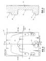
- FIG. 1is a partial cross-sectional view of a magnetic data storage system according to the prior art
- FIG. 2is a partial cross-sectional view taken along line 2 — 2 of FIG. 1 ;
- FIG. 3illustrates the range of motion of a read/write head relative to a magnetic disk
- FIG. 4shows a plan view of an air bearing surface of a read/write head
- FIG. 5is a cross-sectional view of the air bearing surface of FIG. 4 along the line 5 — 5 ;
- FIG. 6shows a plan view of an air bearing surface according to an embodiment of the invention.
- FIG. 3is a plan view of a read/write head 24 disposed over a magnetic disk 16 to further illustrate the range of motion of the suspension 22 and the read/write head 24 relative to the magnetic disk 16 from the inside diameter (ID) to the outside diameter (OD).
- An arrow Rindicates the direction of spin of the magnetic disk 16 and, accordingly, the direction of the air flow past the read/write head 24 . It can be seen that, from the frame of reference of the read/write head 24 , as the read/write head 24 is translated from ID to OD the direction of the air flow beneath it changes. Further, as the read/write head 24 is translated from ID to OD the velocity of the air flow increases. Accordingly, the read/write head 24 needs to be designed to maintain a desired fly height under conditions of changing air flow velocity and direction.
- a skew angle ⁇is the angle formed between a longitudinal axis L of the read/write head 24 and a tangent T.
- the tangent Tis tangential to a diameter D drawn from a center of the magnetic disk 16 through the point on the read/write head where the read and/or write elements are located.
- the skew angle ⁇changes sign as the read/write head 24 is translated between the ID and the OD.
- the skew angle ⁇is defined as a negative value at the ID, a positive value at the OD, and zero when the longitudinal axis L is parallel to the tangent T.
- the side of the read/write head 24 that faces into the airflowis commonly referred to as a leading edge and the opposite side as a trailing edge.
- a leading edgeThe side of the read/write head 24 that faces into the airflow
- a trailing edgeThe side of the read/write head 24 that faces into the airflow.
- ⁇goes from negative to positive, the direction of the airflow relative to the read/write head 24 changes.
- the ID corner of the leading edgefaces into the airflow
- the OD corner of the leading edgefaces into the airflow.
- Other flight characteristicsinclude pitch and roll.
- Pitchis a measure of the height of the leading edge relative to the trailing edge
- rollis a measure of the height of an ID edge relative to the height of an OD edge. It will be appreciated that pitch and roll also need to be controlled to maintain the desired fly height.
- fly heightis atmospheric pressure.
- the air pressure within the enclosure 12will vary with the ambient air pressure.
- the ambient pressureis 1 atmosphere (atm), however, at 10,000 feet above sea level ambient air pressure falls to approximately 0.7 atm, and at 18,000 feet above sea level ambient air pressure falls to approximately 0.5 atm.
- the degree of fly height reduction as a function of decreasing air pressurevaries as a function of skew angle. Specifically, since the air flow velocity at the ID is lower than at the OD, decreasing the air pressure causes a greater lowering of the fly height at the ID than at the OD.
- FIG. 4is a plan view of an air bearing surface (ABS) 40 of a read/write head 24 and FIG. 5 is a cross-section through read/write head 24 along the line 5 — 5 .
- the ABS 40is the side of the read/write head that faces the magnetic disk 16 .
- Air bearing surfaces such as ABS 40are carefully engineered structures designed to control the various flight characteristics of the read/write head 24 (e.g., fly height, roll angle, etc.) as the read/write head 24 is translated between ID and OD and as the magnetic disk 16 is started and stopped.
- a typical ABS 40includes a set of pads configured to create regions of positive lift and to define spaces therebetween to provide regions of negative lift.
- positive liftis defined as a force that pushes the read/write head 24 away from the magnetic disk 16
- negative liftis defined as a force that draws the read/write head 24 towards the magnetic disk 16 .
- ABS 40includes a leading edge pad 42 that includes a shallow step portion 44 and an air bearing portion 46 .
- the leading edge pad 42is shaped to provide sufficient lift through the range of air flow directions and air flow velocities that the read/write head 24 encounters in service.
- the air bearing portion 46is the highest portion of the leading edge pad 42 and is therefore the closest surface to the magnetic disk 16 . Since the spacing between the air bearing portion 46 and the magnetic disk 16 is very close, a positive air pressure develops above the air bearing portion 46 .
- a positive air pressureis defined as an air pressure greater than the ambient air pressure. The positive air pressure creates positive lift on the read/write head 24 which pushes the read/write head 24 away from the magnetic disk 16 .
- the shallow step portion 44helps channel the air flow, as it is encountered at the leading edge of the read/write head 24 , into the space between the air bearing portion 46 and the magnetic disk 16 . As above, a positive air pressure is also developed over the shallow step portion 44 that provides further positive lift to the read/write head 24 . However, since the shallow step portion 44 is beneath the air bearing portion 46 , and therefore further from the magnetic disk 16 , the magnitude of the air pressure increase over the shallow step portion 44 is lower than that over the air bearing portion 46 .
- the air bearing portion 46 of the leading edge pad 42tapers back towards the trailing edge of the ABS 40 on both an ID side and an OD side.
- the trailing portions 48 of the air bearing portion 46define therebetween a cavity 50 that is lower than the shallow step portion 44 .
- a negative air pressuredevelops within the cavity 50 and exerts a negative lift on the read/write head 24 drawing it closer to the magnetic disk 16 .
- the magnitude of the force drawing the read/write head 24 towards the magnetic disk 16depends, in part, on the depth of the cavity 50 and its surface area.
- the negative lift produced by the cavity 50not only serves to cause the read/write head 24 to fly closer to the magnetic disk 16 , but also helps stabilize the fly height against perturbations.
- the read/write head 24includes read and write elements that are exposed to the magnetic disk 16 at the ABS 40 . Since the highest reading and writing performances are achieved by minimizing the spacing between the read and write elements and the magnetic disk 16 , the flight characteristics of the read/write head 24 are tailored so that the read and write elements are at the closest point to the magnetic disk 16 . Accordingly, the read and write elements are positioned near the trailing edge of the read/write head 24 and the trailing edge is provided with a lower amount of positive lift than the leading edge so that the read/write head 24 maintains a positive pitch angle in flight.
- a positive pitch angleis defined as a flight characteristic in which the leading edge is further from the magnetic disk 16 than the trailing edge.
- ABS 40is therefore provided with a trailing edge pad 51 to provide lift to the trailing edge.
- the trailing edge pad 51is provided with a smaller surface area than that of the leading edge pad 42 so that the trailing edge pad 51 will provide less lift than the leading edge pad 42 to cause the trailing edge to fly lower (i.e., closer) to the magnetic disk 16 .
- the trailing edge pad 51is provided with a trailing shallow step portion 52 and a trailing air bearing portion 54 that are analogous in function to the shallow step portion 44 and the air bearing portion 46 of the leading edge pad 42 .
- the shallow step portions 44 and 52are sub substantially coplanar, as are the air bearing portions 46 and 54 .
- the trailing edge pad 51is positioned proximate to the trailing edge, as shown, to position the transducer 56 near the point on the ABS 40 that is closest to the magnetic disk 16 during flight.
- the trailing edge pad 51is therefore approximately centered on a longitudinal axis of the ABS 40 .
- the position and shape of the trailing edge pad 51further defines the cavity 50 and creates ID and OD channels through which air can flow out of the cavity 50 .
- Side pads 60 and 62serve to control roll of the read/write head 24 around a transverse axis of the ABS 40 by providing additional lift towards the trailing edge of the ABS on both the ID and OD sides.
- the shape and position of the side pads 60 and 62further define the cavity 50 and further narrow the ID and OD channels.
- the side pads 60 and 62include side shallow step portions 64 and 66 , and side air bearing portions 68 and 70 that are analogous in function and substantially coplanar with the shallow step portion 44 and the air bearing portion 46 of the leading edge pad 42 .
- the side pads 60 and 62are integral with the trailing portions 48 of the leading edge pad 42 .
- a read/write head 24 that can be used with a variety of magnetic disk 16 rotation ratesis commonly referred to as having an RPM insensitive ABS 40 .
- RPM insensitive ABS 40Towards the end of an RPM insensitive ABS 40 , one solution has been to deepen the cavity 50 by providing higher pads 42 , 51 , 60 , and 62 . Increasing the depth of the cavity 50 further lowers the air pressure within the cavity 50 during flight at a given air flow speed.
- a deeper cavity 50creates proportionately more negative lift than the pads 42 , 51 , 60 and 62 provide positive lift to keep the fly height within acceptable limits when the read/write head 24 is at the OD and at the highest rotation rate.
- increasing the height of the pads 42 , 51 , 60 and 62tends to worsen the decrease in fly height as a function of decreasing ambient air pressure.
- Another design approach that has been found to both minimize changes in fly height as functions of both magnetic disk 16 rotation rate and ambient air pressureis to define further sub-cavaties within the cavity 50 .
- the use of sub-cavities within the cavity 50has been successful, the sub-cavities cost more to manufacture because they require additional masking and etching steps (“triple-etch”).
- FIG. 6is a plan view of an air bearing surface (ABS) 100 of a read/write head of the invention.
- ABS 100is similar in many respects to ABS 40 .
- ABS 100further includes, however, a cavity patch 104 within a cavity 106 defined between a leading edge pad 108 , a trailing edge pad 110 , and in some embodiments, side pads 112 and 114 .
- the cavity patch 104can be of any height greater than that of the cavity 106 , but should not exceed that of air bearing portions 116 and 118 .
- the height of the cavity patch 104is that of either the air bearing portions 116 and 118 or that of shallow step portions 120 and 122 to allow the cavity patch 104 to be created without departing from a double-etch manufacturing process.
- the cavity patch 104can include more than one level in the same manner as the leading edge pad 108 and the side pads 112 and 114 .
- the cavity patch 104can be split into two or more separate features.
- the size, shape, and location of the cavity patch 104 shown in FIG. 5have been optimized for that particular configuration of the leading edge pad 108 , trailing edge pad 110 , and side pads 112 and 114 . In those embodiments with other pad configurations the size, shape, and location of the cavity patch 104 will, of course, be different. Optimizing these parameters is best performed through computer modeling. Such modeling is a well known tool in air bearing design. Accordingly, although the following general relationships are noted, they must be evaluated within the context of the air flow around and over the various pads of any particular design being considered.
- the cavity patch 104creates a region of positive pressure within the cavity 106 that tends to offset the overall negative lift of the cavity 106 .
- the higher the cavity patch 104the greater the positive pressure and the greater the lift that will be created to offset the overall negative lift of the cavity 106 .
- increasing the surface area of the cavity patch 104increases the positive pressure and lift.
- increasing the surface area of the cavity patch 104is achieved at the expense of the surface area of the cavity 106 . So increasing the surface area of the cavity patch 104 both increases the positive lift of the cavity patch 104 and reduces the negative lift of the cavity 106 .
- the location of the cavity patch 104 in preferred embodimentsis biased to the ID side of the ABS 100 as shown in FIG. 5 . Biasing the cavity patch 104 to the ID side in this manner is performed to compensate for the variations in air flow velocity and direction as a function of skew angle. As noted above, when skew angle is negative the ID corner of the leading edge faces into the air flow and the air flow velocity is low. As the skew angle shifts to positive the air flow velocity increases and the direction of the air flow shifts so that the OD corner of the leading edge faces into it.
- Table 1shows improved fly height insensitivity to changes of altitude between sea level and 10,000 feet elevation
- Table 2shows improved fly height insensitivity to changes of the magnetic disk rotation rate (RPM).
- gap fly heightis reported as a function of disk radii.
- the transducer in the trailing edge padis ideally located at the closest point on the ABS 100 to the magnetic disk surface. The spacing between the transducer and the magnetic disk surface is therefore the parameter measured and reported as the gap fly height.
- the disk radiusis the distance from the center of the disk where the gap fly height measurements were taken and runs from a value near the ID (0.7 inches) to a value near the OD (1.7 inches).
- Gap Fly Height as a Function of Disk rotation Rate and Disk RadiusGap Fly Height Gap Fly Height Disk Radii Without Patch With Patch RPM (inches) ( ⁇ ′′) ( ⁇ ′′) 7200 0.7 0.39 0.40 7200 0.8 0.41 0.40 7200 1.3 0.41 0.40 7200 1.7 0.40 0.39 5400 0.7 0.41 0.41 5400 0.8 0.44 0.43 5400 1.3 0.44 0.42 5400 1.7 0.41 0.39
- the gap fly heightdrops significantly, ranging from 0.25 ⁇ ′′ near the disk ID to 0.31 ⁇ ′′ near the disk OD.
- the variation in the gap fly height at sea level air pressure and at 7200 RPM as a function of skewis improved compared to the read/write head with ABS 40 .
- the gap fly heightvaries between 0.39 ⁇ ′′ and 0.40 ⁇ ′′ for the ABS 100 compared to a range of 0.39 ⁇ ′′ to 0.41 ⁇ ′′ for ABS 40 .
- the gap fly height for ABS 100varies between 0.39 ⁇ ′′ and 0.43 ⁇ ′′ a slightly larger variation than shown by ABS 40 (0.41 ⁇ ′′ to 0.44 ⁇ ′′).
- the effect of ABS 100 on the gap fly height of a read/write head under the conditions of sea level air pressure and 5400 RPMis to reduce the maximum gap fly height from 0.4 ⁇ ′′ to 0.43 ⁇ ′′.
- ABS 100 with the cavity patch 104is seen at a disk rotation rate of 7200 RPM when the air pressure is lowered from that at sea level to that at 10,000 feet.
- the gap fly height near the disk IDis improved from 0.25 ⁇ ′′ to 0.28 ⁇ ′′, and at the OD is improved from 0.31 ⁇ ′′ to 0.32 ⁇ ′′.
- the variation in gap fly height as a function of skewis narrowed from 0.06 ⁇ ′′ to 0.04 ⁇ ′′.
- the cavity patch 104keeps the gap fly height in a narrower range of only 0.28 ⁇ ′′ to 0.43 ⁇ ′′ compared to a range of 0.25 ⁇ ′′ to 0.44 ⁇ ′′ for ABS 40 without the cavity patch 104 .
- a double-etch method for fabricating a read/write head with an RPM insensitive air bearing surfaceis also disclosed herein.
- the methodincludes two masking and etching steps.
- first masking stepseveral portions of a side of the read/write head are masked. These portions will ultimately become the air bearing portions of the leading edge pad and trailing edge pad of the air bearing surface described above.
- the first masking stepalso includes masking portions to become the air bearing portions of side pads. Methods for masking, including the use of photolithography, are well known in the art.
- the side of the read/write headis etched to a first depth beneath a depth of the air bearing portions.
- This first etchdefines what will become the height difference between the air bearing portions and the shallow step portions of the air bearing surface and is preferably in the range of about 3 ⁇ ′′ to about 10 ⁇ ′′.
- the air bearing portionsare protected by the mask produced in the first masking step. Methods for etching, such as reactive ion etching (RIE), are well known in the art.
- RIEreactive ion etching
- This stepcan also include, after the etch processing, stripping remaining mask material and any necessary cleaning steps.
- the air bearing portions masked in the first masking stepare again masked to continue to preserve them. Additionally, in the second masking step certain portions of the surface at the first depth are also masked. These portions of the surface at the first depth include a leading edge shallow step portion and a trailing edge shallow step portion, and in some embodiments can also include two side shallow step portions. After a further etching step, these portions will become the shallow step portions of the air bearing surface described above. Yet another portion of the surface at the first depth that is masked is a cavity patch portion disposed between the masked shallow step portions. The cavity patch portion masked at the first depth will ultimately become the cavity patch of the air bearing surface described above. As above, methods for masking are well known in the art.
- the sideis etched to a second depth beneath the first depth.
- the second etching stepetches the side to the second depth wherever the side is not protected by the mask formed during second masking step.
- the sum of the first and second depthsis preferably in the range of about 50 ⁇ ′′ to about 120 ⁇ ′′. Accordingly, the leading edge pad, the trailing edge pad, and the cavity patch, and in some embodiments two side pads, are completed by the second etching step, and a cavity of the air bearing surface described above is formed around the cavity patch and between the leading and trailing edge pads.
- methods for etchingare well known in the art.
Landscapes
- Adjustment Of The Magnetic Head Position Track Following On Tapes (AREA)
Abstract
Description
| TABLE 1 |
| Gap Fly Height as a Function of Altitude and Disk Radius |
| Gap Fly Height | Gap Fly Height | ||||
| Disk Radii | Without Patch | With Patch | |||
| Altitude | (inches) | (μ″) | (μ″) | ||
| Sea Level | 0.7 | 0.39 | 0.40 | ||
| Sea Level | 0.8 | 0.41 | 0.40 | ||
| Sea Level | 1.3 | 0.41 | 0.40 | ||
| Sea Level | 1.7 | 0.40 | 0.39 | ||
| 10,000 ft. | 0.7 | 0.25 | 0.28 | ||
| 10,000 ft. | 0.8 | 0.27 | 0.29 | ||
| 10,000 ft. | 1.3 | 0.29 | 0.30 | ||
| 10,000 ft. | 1.7 | 0.31 | 0.32 | ||
| TABLE 2 |
| Gap Fly Height as a Function of Disk rotation Rate and Disk Radius |
| Gap Fly Height | Gap Fly Height | ||||
| Disk Radii | Without Patch | With Patch | |||
| RPM | (inches) | (μ″) | (μ″) | ||
| 7200 | 0.7 | 0.39 | 0.40 | ||
| 7200 | 0.8 | 0.41 | 0.40 | ||
| 7200 | 1.3 | 0.41 | 0.40 | ||
| 7200 | 1.7 | 0.40 | 0.39 | ||
| 5400 | 0.7 | 0.41 | 0.41 | ||
| 5400 | 0.8 | 0.44 | 0.43 | ||
| 5400 | 1.3 | 0.44 | 0.42 | ||
| 5400 | 1.7 | 0.41 | 0.39 | ||
Claims (8)
Priority Applications (3)
| Application Number | Priority Date | Filing Date | Title |
|---|---|---|---|
| US10/222,042US6879464B2 (en) | 2002-08-16 | 2002-08-16 | Air bearing having a cavity patch surface coplanar with a leading edge pad surface |
| PCT/US2003/025923WO2004017304A2 (en) | 2002-08-16 | 2003-08-18 | Air bearing design with a patch in cavity |
| AU2003263918AAU2003263918A1 (en) | 2002-08-16 | 2003-08-18 | Air bearing design with a patch in cavity |
Applications Claiming Priority (1)
| Application Number | Priority Date | Filing Date | Title |
|---|---|---|---|
| US10/222,042US6879464B2 (en) | 2002-08-16 | 2002-08-16 | Air bearing having a cavity patch surface coplanar with a leading edge pad surface |
Publications (2)
| Publication Number | Publication Date |
|---|---|
| US20040032694A1 US20040032694A1 (en) | 2004-02-19 |
| US6879464B2true US6879464B2 (en) | 2005-04-12 |
Family
ID=31714857
Family Applications (1)
| Application Number | Title | Priority Date | Filing Date |
|---|---|---|---|
| US10/222,042Expired - LifetimeUS6879464B2 (en) | 2002-08-16 | 2002-08-16 | Air bearing having a cavity patch surface coplanar with a leading edge pad surface |
Country Status (3)
| Country | Link |
|---|---|
| US (1) | US6879464B2 (en) |
| AU (1) | AU2003263918A1 (en) |
| WO (1) | WO2004017304A2 (en) |
Cited By (139)
| Publication number | Priority date | Publication date | Assignee | Title |
|---|---|---|---|---|
| US20040201924A1 (en)* | 2003-04-10 | 2004-10-14 | Alps Electric Co., Ltd. | Magnetic head apparatus having magnetic head slider and magnetic disk apparatus equipped with magnetic head apparatus |
| US20050213252A1 (en)* | 2004-03-26 | 2005-09-29 | Ki-Ook Park | Method and apparatus supporting a slider having multiple deflection rails in a negative pressure pocket for a hard disk drive |
| US20050264913A1 (en)* | 2004-05-12 | 2005-12-01 | Hitachi Global Storage Technologies Netherlands B.V. | System, method, and apparatus for improving the multiple velocity performance and write element protrusion compensation of disk drive sliders |
| US20070297080A1 (en)* | 2006-06-23 | 2007-12-27 | Lee Sungchang | Apparatus and method for bending a slider to create rounded corners on its trailing edge in a hard disk drive |
| US7477486B1 (en) | 2005-12-07 | 2009-01-13 | Western Digital (Fremont), Llc | Air bearing slider with a side pad having a shallow recess depth |
| US8199437B1 (en) | 2010-03-09 | 2012-06-12 | Western Digital (Fremont), Llc | Head with an air bearing surface having a particle fence separated from a leading pad by a continuous moat |
| US8830628B1 (en) | 2009-02-23 | 2014-09-09 | Western Digital (Fremont), Llc | Method and system for providing a perpendicular magnetic recording head |
| US8879207B1 (en) | 2011-12-20 | 2014-11-04 | Western Digital (Fremont), Llc | Method for providing a side shield for a magnetic recording transducer using an air bridge |
| US8883017B1 (en) | 2013-03-12 | 2014-11-11 | Western Digital (Fremont), Llc | Method and system for providing a read transducer having seamless interfaces |
| US8917581B1 (en) | 2013-12-18 | 2014-12-23 | Western Digital Technologies, Inc. | Self-anneal process for a near field transducer and chimney in a hard disk drive assembly |
| US8923102B1 (en) | 2013-07-16 | 2014-12-30 | Western Digital (Fremont), Llc | Optical grating coupling for interferometric waveguides in heat assisted magnetic recording heads |
| US8947985B1 (en) | 2013-07-16 | 2015-02-03 | Western Digital (Fremont), Llc | Heat assisted magnetic recording transducers having a recessed pole |
| US8953422B1 (en) | 2014-06-10 | 2015-02-10 | Western Digital (Fremont), Llc | Near field transducer using dielectric waveguide core with fine ridge feature |
| US8958272B1 (en) | 2014-06-10 | 2015-02-17 | Western Digital (Fremont), Llc | Interfering near field transducer for energy assisted magnetic recording |
| US8970988B1 (en) | 2013-12-31 | 2015-03-03 | Western Digital (Fremont), Llc | Electric gaps and method for making electric gaps for multiple sensor arrays |
| US8971160B1 (en) | 2013-12-19 | 2015-03-03 | Western Digital (Fremont), Llc | Near field transducer with high refractive index pin for heat assisted magnetic recording |
| US8976635B1 (en) | 2014-06-10 | 2015-03-10 | Western Digital (Fremont), Llc | Near field transducer driven by a transverse electric waveguide for energy assisted magnetic recording |
| US8982508B1 (en) | 2011-10-31 | 2015-03-17 | Western Digital (Fremont), Llc | Method for providing a side shield for a magnetic recording transducer |
| US8980109B1 (en) | 2012-12-11 | 2015-03-17 | Western Digital (Fremont), Llc | Method for providing a magnetic recording transducer using a combined main pole and side shield CMP for a wraparound shield scheme |
| US8984740B1 (en) | 2012-11-30 | 2015-03-24 | Western Digital (Fremont), Llc | Process for providing a magnetic recording transducer having a smooth magnetic seed layer |
| US8988812B1 (en) | 2013-11-27 | 2015-03-24 | Western Digital (Fremont), Llc | Multi-sensor array configuration for a two-dimensional magnetic recording (TDMR) operation |
| US8988825B1 (en) | 2014-02-28 | 2015-03-24 | Western Digital (Fremont, LLC | Method for fabricating a magnetic writer having half-side shields |
| US8993217B1 (en) | 2013-04-04 | 2015-03-31 | Western Digital (Fremont), Llc | Double exposure technique for high resolution disk imaging |
| US8995087B1 (en) | 2006-11-29 | 2015-03-31 | Western Digital (Fremont), Llc | Perpendicular magnetic recording write head having a wrap around shield |
| US8997832B1 (en) | 2010-11-23 | 2015-04-07 | Western Digital (Fremont), Llc | Method of fabricating micrometer scale components |
| US9001467B1 (en) | 2014-03-05 | 2015-04-07 | Western Digital (Fremont), Llc | Method for fabricating side shields in a magnetic writer |
| US9001628B1 (en) | 2013-12-16 | 2015-04-07 | Western Digital (Fremont), Llc | Assistant waveguides for evaluating main waveguide coupling efficiency and diode laser alignment tolerances for hard disk |
| US9007725B1 (en) | 2014-10-07 | 2015-04-14 | Western Digital (Fremont), Llc | Sensor with positive coupling between dual ferromagnetic free layer laminates |
| US9007719B1 (en) | 2013-10-23 | 2015-04-14 | Western Digital (Fremont), Llc | Systems and methods for using double mask techniques to achieve very small features |
| US9007879B1 (en) | 2014-06-10 | 2015-04-14 | Western Digital (Fremont), Llc | Interfering near field transducer having a wide metal bar feature for energy assisted magnetic recording |
| US9013836B1 (en) | 2013-04-02 | 2015-04-21 | Western Digital (Fremont), Llc | Method and system for providing an antiferromagnetically coupled return pole |
| US9042051B2 (en) | 2013-08-15 | 2015-05-26 | Western Digital (Fremont), Llc | Gradient write gap for perpendicular magnetic recording writer |
| US9042208B1 (en) | 2013-03-11 | 2015-05-26 | Western Digital Technologies, Inc. | Disk drive measuring fly height by applying a bias voltage to an electrically insulated write component of a head |
| US9042057B1 (en) | 2013-01-09 | 2015-05-26 | Western Digital (Fremont), Llc | Methods for providing magnetic storage elements with high magneto-resistance using Heusler alloys |
| US9042058B1 (en) | 2013-10-17 | 2015-05-26 | Western Digital Technologies, Inc. | Shield designed for middle shields in a multiple sensor array |
| US9042052B1 (en) | 2014-06-23 | 2015-05-26 | Western Digital (Fremont), Llc | Magnetic writer having a partially shunted coil |
| US9053735B1 (en) | 2014-06-20 | 2015-06-09 | Western Digital (Fremont), Llc | Method for fabricating a magnetic writer using a full-film metal planarization |
| US9064507B1 (en) | 2009-07-31 | 2015-06-23 | Western Digital (Fremont), Llc | Magnetic etch-stop layer for magnetoresistive read heads |
| US9064528B1 (en) | 2013-05-17 | 2015-06-23 | Western Digital Technologies, Inc. | Interferometric waveguide usable in shingled heat assisted magnetic recording in the absence of a near-field transducer |
| US9064527B1 (en) | 2013-04-12 | 2015-06-23 | Western Digital (Fremont), Llc | High order tapered waveguide for use in a heat assisted magnetic recording head |
| US9065043B1 (en) | 2012-06-29 | 2015-06-23 | Western Digital (Fremont), Llc | Tunnel magnetoresistance read head with narrow shield-to-shield spacing |
| US9070381B1 (en) | 2013-04-12 | 2015-06-30 | Western Digital (Fremont), Llc | Magnetic recording read transducer having a laminated free layer |
| US9082423B1 (en) | 2013-12-18 | 2015-07-14 | Western Digital (Fremont), Llc | Magnetic recording write transducer having an improved trailing surface profile |
| US9087534B1 (en) | 2011-12-20 | 2015-07-21 | Western Digital (Fremont), Llc | Method and system for providing a read transducer having soft and hard magnetic bias structures |
| US9087527B1 (en) | 2014-10-28 | 2015-07-21 | Western Digital (Fremont), Llc | Apparatus and method for middle shield connection in magnetic recording transducers |
| US9093639B2 (en) | 2012-02-21 | 2015-07-28 | Western Digital (Fremont), Llc | Methods for manufacturing a magnetoresistive structure utilizing heating and cooling |
| US9104107B1 (en) | 2013-04-03 | 2015-08-11 | Western Digital (Fremont), Llc | DUV photoresist process |
| US9111558B1 (en) | 2014-03-14 | 2015-08-18 | Western Digital (Fremont), Llc | System and method of diffractive focusing of light in a waveguide |
| US9111564B1 (en) | 2013-04-02 | 2015-08-18 | Western Digital (Fremont), Llc | Magnetic recording writer having a main pole with multiple flare angles |
| US9111550B1 (en) | 2014-12-04 | 2015-08-18 | Western Digital (Fremont), Llc | Write transducer having a magnetic buffer layer spaced between a side shield and a write pole by non-magnetic layers |
| US9123362B1 (en) | 2011-03-22 | 2015-09-01 | Western Digital (Fremont), Llc | Methods for assembling an electrically assisted magnetic recording (EAMR) head |
| US9123358B1 (en) | 2012-06-11 | 2015-09-01 | Western Digital (Fremont), Llc | Conformal high moment side shield seed layer for perpendicular magnetic recording writer |
| US9123359B1 (en) | 2010-12-22 | 2015-09-01 | Western Digital (Fremont), Llc | Magnetic recording transducer with sputtered antiferromagnetic coupling trilayer between plated ferromagnetic shields and method of fabrication |
| US9123374B1 (en) | 2015-02-12 | 2015-09-01 | Western Digital (Fremont), Llc | Heat assisted magnetic recording writer having an integrated polarization rotation plate |
| US9135930B1 (en) | 2014-03-06 | 2015-09-15 | Western Digital (Fremont), Llc | Method for fabricating a magnetic write pole using vacuum deposition |
| US9135937B1 (en) | 2014-05-09 | 2015-09-15 | Western Digital (Fremont), Llc | Current modulation on laser diode for energy assisted magnetic recording transducer |
| US9142233B1 (en) | 2014-02-28 | 2015-09-22 | Western Digital (Fremont), Llc | Heat assisted magnetic recording writer having a recessed pole |
| US9147404B1 (en) | 2015-03-31 | 2015-09-29 | Western Digital (Fremont), Llc | Method and system for providing a read transducer having a dual free layer |
| US9147408B1 (en) | 2013-12-19 | 2015-09-29 | Western Digital (Fremont), Llc | Heated AFM layer deposition and cooling process for TMR magnetic recording sensor with high pinning field |
| US9153255B1 (en) | 2014-03-05 | 2015-10-06 | Western Digital (Fremont), Llc | Method for fabricating a magnetic writer having an asymmetric gap and shields |
| US9183854B2 (en) | 2014-02-24 | 2015-11-10 | Western Digital (Fremont), Llc | Method to make interferometric taper waveguide for HAMR light delivery |
| US9190079B1 (en) | 2014-09-22 | 2015-11-17 | Western Digital (Fremont), Llc | Magnetic write pole having engineered radius of curvature and chisel angle profiles |
| US9190090B1 (en) | 2014-12-24 | 2015-11-17 | Western Digital (Fremont), Llc | Multi step lube blocking air bearing area configuration |
| US9190085B1 (en) | 2014-03-12 | 2015-11-17 | Western Digital (Fremont), Llc | Waveguide with reflective grating for localized energy intensity |
| US9194692B1 (en) | 2013-12-06 | 2015-11-24 | Western Digital (Fremont), Llc | Systems and methods for using white light interferometry to measure undercut of a bi-layer structure |
| US9202493B1 (en) | 2014-02-28 | 2015-12-01 | Western Digital (Fremont), Llc | Method of making an ultra-sharp tip mode converter for a HAMR head |
| US9202480B2 (en) | 2009-10-14 | 2015-12-01 | Western Digital (Fremont), LLC. | Double patterning hard mask for damascene perpendicular magnetic recording (PMR) writer |
| US9214169B1 (en) | 2014-06-20 | 2015-12-15 | Western Digital (Fremont), Llc | Magnetic recording read transducer having a laminated free layer |
| US9214172B2 (en) | 2013-10-23 | 2015-12-15 | Western Digital (Fremont), Llc | Method of manufacturing a magnetic read head |
| US9214165B1 (en) | 2014-12-18 | 2015-12-15 | Western Digital (Fremont), Llc | Magnetic writer having a gradient in saturation magnetization of the shields |
| US9213322B1 (en) | 2012-08-16 | 2015-12-15 | Western Digital (Fremont), Llc | Methods for providing run to run process control using a dynamic tuner |
| US9230565B1 (en) | 2014-06-24 | 2016-01-05 | Western Digital (Fremont), Llc | Magnetic shield for magnetic recording head |
| US9236560B1 (en) | 2014-12-08 | 2016-01-12 | Western Digital (Fremont), Llc | Spin transfer torque tunneling magnetoresistive device having a laminated free layer with perpendicular magnetic anisotropy |
| US9245545B1 (en) | 2013-04-12 | 2016-01-26 | Wester Digital (Fremont), Llc | Short yoke length coils for magnetic heads in disk drives |
| US9245543B1 (en) | 2010-06-25 | 2016-01-26 | Western Digital (Fremont), Llc | Method for providing an energy assisted magnetic recording head having a laser integrally mounted to the slider |
| US9245562B1 (en) | 2015-03-30 | 2016-01-26 | Western Digital (Fremont), Llc | Magnetic recording writer with a composite main pole |
| US9251813B1 (en) | 2009-04-19 | 2016-02-02 | Western Digital (Fremont), Llc | Method of making a magnetic recording head |
| US9263071B1 (en) | 2015-03-31 | 2016-02-16 | Western Digital (Fremont), Llc | Flat NFT for heat assisted magnetic recording |
| US9263067B1 (en) | 2013-05-29 | 2016-02-16 | Western Digital (Fremont), Llc | Process for making PMR writer with constant side wall angle |
| US9269382B1 (en) | 2012-06-29 | 2016-02-23 | Western Digital (Fremont), Llc | Method and system for providing a read transducer having improved pinning of the pinned layer at higher recording densities |
| US9275657B1 (en) | 2013-08-14 | 2016-03-01 | Western Digital (Fremont), Llc | Process for making PMR writer with non-conformal side gaps |
| US9280990B1 (en) | 2013-12-11 | 2016-03-08 | Western Digital (Fremont), Llc | Method for fabricating a magnetic writer using multiple etches |
| US9286919B1 (en) | 2014-12-17 | 2016-03-15 | Western Digital (Fremont), Llc | Magnetic writer having a dual side gap |
| US9287494B1 (en) | 2013-06-28 | 2016-03-15 | Western Digital (Fremont), Llc | Magnetic tunnel junction (MTJ) with a magnesium oxide tunnel barrier |
| US9305583B1 (en) | 2014-02-18 | 2016-04-05 | Western Digital (Fremont), Llc | Method for fabricating a magnetic writer using multiple etches of damascene materials |
| US9312064B1 (en) | 2015-03-02 | 2016-04-12 | Western Digital (Fremont), Llc | Method to fabricate a magnetic head including ion milling of read gap using dual layer hard mask |
| US9318130B1 (en) | 2013-07-02 | 2016-04-19 | Western Digital (Fremont), Llc | Method to fabricate tunneling magnetic recording heads with extended pinned layer |
| US9336814B1 (en) | 2013-03-12 | 2016-05-10 | Western Digital (Fremont), Llc | Inverse tapered waveguide for use in a heat assisted magnetic recording head |
| US9343086B1 (en) | 2013-09-11 | 2016-05-17 | Western Digital (Fremont), Llc | Magnetic recording write transducer having an improved sidewall angle profile |
| US9343087B1 (en) | 2014-12-21 | 2016-05-17 | Western Digital (Fremont), Llc | Method for fabricating a magnetic writer having half shields |
| US9343098B1 (en) | 2013-08-23 | 2016-05-17 | Western Digital (Fremont), Llc | Method for providing a heat assisted magnetic recording transducer having protective pads |
| US9349392B1 (en) | 2012-05-24 | 2016-05-24 | Western Digital (Fremont), Llc | Methods for improving adhesion on dielectric substrates |
| US9349394B1 (en) | 2013-10-18 | 2016-05-24 | Western Digital (Fremont), Llc | Method for fabricating a magnetic writer having a gradient side gap |
| US9361914B1 (en) | 2014-06-18 | 2016-06-07 | Western Digital (Fremont), Llc | Magnetic sensor with thin capping layer |
| US9361913B1 (en) | 2013-06-03 | 2016-06-07 | Western Digital (Fremont), Llc | Recording read heads with a multi-layer AFM layer methods and apparatuses |
| US9368134B1 (en) | 2010-12-16 | 2016-06-14 | Western Digital (Fremont), Llc | Method and system for providing an antiferromagnetically coupled writer |
| US9384763B1 (en) | 2015-03-26 | 2016-07-05 | Western Digital (Fremont), Llc | Dual free layer magnetic reader having a rear bias structure including a soft bias layer |
| US9384765B1 (en) | 2015-09-24 | 2016-07-05 | Western Digital (Fremont), Llc | Method and system for providing a HAMR writer having improved optical efficiency |
| US9396742B1 (en) | 2012-11-30 | 2016-07-19 | Western Digital (Fremont), Llc | Magnetoresistive sensor for a magnetic storage system read head, and fabrication method thereof |
| US9396743B1 (en) | 2014-02-28 | 2016-07-19 | Western Digital (Fremont), Llc | Systems and methods for controlling soft bias thickness for tunnel magnetoresistance readers |
| US9406331B1 (en) | 2013-06-17 | 2016-08-02 | Western Digital (Fremont), Llc | Method for making ultra-narrow read sensor and read transducer device resulting therefrom |
| US9424866B1 (en) | 2015-09-24 | 2016-08-23 | Western Digital (Fremont), Llc | Heat assisted magnetic recording write apparatus having a dielectric gap |
| US9431039B1 (en) | 2013-05-21 | 2016-08-30 | Western Digital (Fremont), Llc | Multiple sensor array usable in two-dimensional magnetic recording |
| US9431047B1 (en) | 2013-05-01 | 2016-08-30 | Western Digital (Fremont), Llc | Method for providing an improved AFM reader shield |
| US9431031B1 (en) | 2015-03-24 | 2016-08-30 | Western Digital (Fremont), Llc | System and method for magnetic transducers having multiple sensors and AFC shields |
| US9431038B1 (en) | 2015-06-29 | 2016-08-30 | Western Digital (Fremont), Llc | Method for fabricating a magnetic write pole having an improved sidewall angle profile |
| US9431032B1 (en) | 2013-08-14 | 2016-08-30 | Western Digital (Fremont), Llc | Electrical connection arrangement for a multiple sensor array usable in two-dimensional magnetic recording |
| US9431044B1 (en) | 2014-05-07 | 2016-08-30 | Western Digital (Fremont), Llc | Slider having shock and particle resistance |
| US9437251B1 (en) | 2014-12-22 | 2016-09-06 | Western Digital (Fremont), Llc | Apparatus and method having TDMR reader to reader shunts |
| US9441938B1 (en) | 2013-10-08 | 2016-09-13 | Western Digital (Fremont), Llc | Test structures for measuring near field transducer disc length |
| US9443541B1 (en) | 2015-03-24 | 2016-09-13 | Western Digital (Fremont), Llc | Magnetic writer having a gradient in saturation magnetization of the shields and return pole |
| US9449621B1 (en) | 2015-03-26 | 2016-09-20 | Western Digital (Fremont), Llc | Dual free layer magnetic reader having a rear bias structure having a high aspect ratio |
| US9449625B1 (en) | 2014-12-24 | 2016-09-20 | Western Digital (Fremont), Llc | Heat assisted magnetic recording head having a plurality of diffusion barrier layers |
| US9472216B1 (en) | 2015-09-23 | 2016-10-18 | Western Digital (Fremont), Llc | Differential dual free layer magnetic reader |
| US9484051B1 (en) | 2015-11-09 | 2016-11-01 | The Provost, Fellows, Foundation Scholars and the other members of Board, of the College of the Holy and Undivided Trinity of Queen Elizabeth near Dublin | Method and system for reducing undesirable reflections in a HAMR write apparatus |
| US9508372B1 (en) | 2015-06-03 | 2016-11-29 | Western Digital (Fremont), Llc | Shingle magnetic writer having a low sidewall angle pole |
| US9508365B1 (en) | 2015-06-24 | 2016-11-29 | Western Digital (Fremont), LLC. | Magnetic reader having a crystal decoupling structure |
| US9508363B1 (en) | 2014-06-17 | 2016-11-29 | Western Digital (Fremont), Llc | Method for fabricating a magnetic write pole having a leading edge bevel |
| US9530443B1 (en) | 2015-06-25 | 2016-12-27 | Western Digital (Fremont), Llc | Method for fabricating a magnetic recording device having a high aspect ratio structure |
| US9564150B1 (en) | 2015-11-24 | 2017-02-07 | Western Digital (Fremont), Llc | Magnetic read apparatus having an improved read sensor isolation circuit |
| US9595273B1 (en) | 2015-09-30 | 2017-03-14 | Western Digital (Fremont), Llc | Shingle magnetic writer having nonconformal shields |
| US9646639B2 (en) | 2015-06-26 | 2017-05-09 | Western Digital (Fremont), Llc | Heat assisted magnetic recording writer having integrated polarization rotation waveguides |
| US9666214B1 (en) | 2015-09-23 | 2017-05-30 | Western Digital (Fremont), Llc | Free layer magnetic reader that may have a reduced shield-to-shield spacing |
| US9704523B1 (en) | 2016-01-07 | 2017-07-11 | Western Digital Technologies, Inc. | Slider with tunnel feature |
| US9721595B1 (en) | 2014-12-04 | 2017-08-01 | Western Digital (Fremont), Llc | Method for providing a storage device |
| US9741366B1 (en) | 2014-12-18 | 2017-08-22 | Western Digital (Fremont), Llc | Method for fabricating a magnetic writer having a gradient in saturation magnetization of the shields |
| US9740805B1 (en) | 2015-12-01 | 2017-08-22 | Western Digital (Fremont), Llc | Method and system for detecting hotspots for photolithographically-defined devices |
| US9754611B1 (en) | 2015-11-30 | 2017-09-05 | Western Digital (Fremont), Llc | Magnetic recording write apparatus having a stepped conformal trailing shield |
| US9767831B1 (en) | 2015-12-01 | 2017-09-19 | Western Digital (Fremont), Llc | Magnetic writer having convex trailing surface pole and conformal write gap |
| US9786301B1 (en) | 2014-12-02 | 2017-10-10 | Western Digital (Fremont), Llc | Apparatuses and methods for providing thin shields in a multiple sensor array |
| US9799351B1 (en) | 2015-11-30 | 2017-10-24 | Western Digital (Fremont), Llc | Short yoke length writer having assist coils |
| US9812155B1 (en) | 2015-11-23 | 2017-11-07 | Western Digital (Fremont), Llc | Method and system for fabricating high junction angle read sensors |
| US9842615B1 (en) | 2015-06-26 | 2017-12-12 | Western Digital (Fremont), Llc | Magnetic reader having a nonmagnetic insertion layer for the pinning layer |
| US9858951B1 (en) | 2015-12-01 | 2018-01-02 | Western Digital (Fremont), Llc | Method for providing a multilayer AFM layer in a read sensor |
| US9881638B1 (en) | 2014-12-17 | 2018-01-30 | Western Digital (Fremont), Llc | Method for providing a near-field transducer (NFT) for a heat assisted magnetic recording (HAMR) device |
| US9934811B1 (en) | 2014-03-07 | 2018-04-03 | Western Digital (Fremont), Llc | Methods for controlling stray fields of magnetic features using magneto-elastic anisotropy |
| US9953670B1 (en) | 2015-11-10 | 2018-04-24 | Western Digital (Fremont), Llc | Method and system for providing a HAMR writer including a multi-mode interference device |
| US10037770B1 (en) | 2015-11-12 | 2018-07-31 | Western Digital (Fremont), Llc | Method for providing a magnetic recording write apparatus having a seamless pole |
| US10074387B1 (en) | 2014-12-21 | 2018-09-11 | Western Digital (Fremont), Llc | Method and system for providing a read transducer having symmetric antiferromagnetically coupled shields |
Families Citing this family (9)
| Publication number | Priority date | Publication date | Assignee | Title |
|---|---|---|---|---|
| US7277255B2 (en)* | 2003-10-21 | 2007-10-02 | Matsushita Electric Industrial Co., Ltd. | Head slider with positive dynamic pressure generating section |
| JP4293933B2 (en)* | 2004-03-31 | 2009-07-08 | 富士通株式会社 | Head slider of disk device |
| US20060075414A1 (en)* | 2004-10-06 | 2006-04-06 | Robert Rapp | Packaging methodology for adding functionality to a data storage device (disk drive, tape drive, other storage device, or storage subsystem) while maintaining the same form factor, standard size, or allocated size; or by increasing the overall package size to a larger form factor, standard size, or allocated size |
| US7719795B2 (en)* | 2006-11-15 | 2010-05-18 | Western Digital (Fremont), Llc | Head having a transducer heater and an air bearing surface with a flow-diversion dam and pressure-relief trough disposed upstream of the transducer |
| US7616405B2 (en)* | 2006-11-15 | 2009-11-10 | Western Digital (Fremont), Llc | Slider with an air bearing surface having a inter-cavity dam with OD and ID dam surfaces of different heights |
| US7855854B2 (en)* | 2007-04-17 | 2010-12-21 | Western Digital (Fremont), Llc | Head with an air bearing surface having a shallow recessed trailing air flow dam |
| US7872833B2 (en)* | 2007-04-17 | 2011-01-18 | Western Digital (Fremont) , LLC | Head with a transducer overcoat having a trailing air flow dam that is shallowly recessed from an air bearing surface |
| US7916426B2 (en)* | 2007-11-30 | 2011-03-29 | Western Digital (Fremont), Llc | Head with an air bearing surface having left and right leading pressurizing steps, each with short and long regions |
| US8553363B2 (en)* | 2011-04-05 | 2013-10-08 | HGST Netherlands B.V. | Air-bearing surface of head for minimizing contact with disk |
Citations (5)
| Publication number | Priority date | Publication date | Assignee | Title |
|---|---|---|---|---|
| US20020008939A1 (en)* | 2000-04-12 | 2002-01-24 | Boutaghou Zine Eddine | Pad design concepts for slider air-bearings |
| US20020030938A1 (en)* | 2000-07-28 | 2002-03-14 | Zine-Eddine Boutaghou | AAB having cavities for increasing contact stiffness and controlling suction center movement |
| US6477013B1 (en)* | 2000-11-09 | 2002-11-05 | International Business Machines Corporation | Slider air bearing design and method providing writing of a laser field (WOLF) measurement without substantial fly height affect |
| US6529346B2 (en)* | 2000-01-21 | 2003-03-04 | Alps Electric Co., Ltd. | Magnetic head slider with protrusion on surface facing recording medium |
| US20030227717A1 (en)* | 2002-06-07 | 2003-12-11 | Cha Ellis T. | Subambient pressure slider with partitioned subambient area |
- 2002
- 2002-08-16USUS10/222,042patent/US6879464B2/ennot_activeExpired - Lifetime
- 2003
- 2003-08-18WOPCT/US2003/025923patent/WO2004017304A2/ennot_activeApplication Discontinuation
- 2003-08-18AUAU2003263918Apatent/AU2003263918A1/ennot_activeAbandoned
Patent Citations (5)
| Publication number | Priority date | Publication date | Assignee | Title |
|---|---|---|---|---|
| US6529346B2 (en)* | 2000-01-21 | 2003-03-04 | Alps Electric Co., Ltd. | Magnetic head slider with protrusion on surface facing recording medium |
| US20020008939A1 (en)* | 2000-04-12 | 2002-01-24 | Boutaghou Zine Eddine | Pad design concepts for slider air-bearings |
| US20020030938A1 (en)* | 2000-07-28 | 2002-03-14 | Zine-Eddine Boutaghou | AAB having cavities for increasing contact stiffness and controlling suction center movement |
| US6477013B1 (en)* | 2000-11-09 | 2002-11-05 | International Business Machines Corporation | Slider air bearing design and method providing writing of a laser field (WOLF) measurement without substantial fly height affect |
| US20030227717A1 (en)* | 2002-06-07 | 2003-12-11 | Cha Ellis T. | Subambient pressure slider with partitioned subambient area |
Cited By (162)
| Publication number | Priority date | Publication date | Assignee | Title |
|---|---|---|---|---|
| US7145752B2 (en)* | 2003-04-10 | 2006-12-05 | Alps Electric Co., Ltd. | Magnetic head apparatus having magnetic head slider and magnetic disk apparatus equipped with magnetic head apparatus |
| US20040201924A1 (en)* | 2003-04-10 | 2004-10-14 | Alps Electric Co., Ltd. | Magnetic head apparatus having magnetic head slider and magnetic disk apparatus equipped with magnetic head apparatus |
| US7969688B2 (en)* | 2004-03-26 | 2011-06-28 | Samsung Electronics Co., Ltd. | Method and apparatus supporting a slider having multiple deflection rails in a negative pressure pocket for a hard disk drive |
| US20050213252A1 (en)* | 2004-03-26 | 2005-09-29 | Ki-Ook Park | Method and apparatus supporting a slider having multiple deflection rails in a negative pressure pocket for a hard disk drive |
| US7333297B2 (en)* | 2004-03-26 | 2008-02-19 | Samsung Electronics Co., Ltd. | Method and apparatus supporting a slider having multiple deflection rails in a negative pressure pocket for a hard disk drive |
| US20080130173A1 (en)* | 2004-03-26 | 2008-06-05 | Samsung Electronics Co., Ltd. | Method and apparatus supporting a slider having multiple deflection rails in a negative pressure pocket for a hard disk drive |
| US20050264913A1 (en)* | 2004-05-12 | 2005-12-01 | Hitachi Global Storage Technologies Netherlands B.V. | System, method, and apparatus for improving the multiple velocity performance and write element protrusion compensation of disk drive sliders |
| US7324306B2 (en)* | 2004-05-12 | 2008-01-29 | Hitachiglobal Storage Technologies Netherlands Bv | System, method, and apparatus for improving the multiple velocity performance and write element protrusion compensation of disk drive sliders |
| US7477486B1 (en) | 2005-12-07 | 2009-01-13 | Western Digital (Fremont), Llc | Air bearing slider with a side pad having a shallow recess depth |
| US20070297080A1 (en)* | 2006-06-23 | 2007-12-27 | Lee Sungchang | Apparatus and method for bending a slider to create rounded corners on its trailing edge in a hard disk drive |
| US8995087B1 (en) | 2006-11-29 | 2015-03-31 | Western Digital (Fremont), Llc | Perpendicular magnetic recording write head having a wrap around shield |
| US8830628B1 (en) | 2009-02-23 | 2014-09-09 | Western Digital (Fremont), Llc | Method and system for providing a perpendicular magnetic recording head |
| US9251813B1 (en) | 2009-04-19 | 2016-02-02 | Western Digital (Fremont), Llc | Method of making a magnetic recording head |
| US9064507B1 (en) | 2009-07-31 | 2015-06-23 | Western Digital (Fremont), Llc | Magnetic etch-stop layer for magnetoresistive read heads |
| US9202480B2 (en) | 2009-10-14 | 2015-12-01 | Western Digital (Fremont), LLC. | Double patterning hard mask for damascene perpendicular magnetic recording (PMR) writer |
| US8199437B1 (en) | 2010-03-09 | 2012-06-12 | Western Digital (Fremont), Llc | Head with an air bearing surface having a particle fence separated from a leading pad by a continuous moat |
| US9245543B1 (en) | 2010-06-25 | 2016-01-26 | Western Digital (Fremont), Llc | Method for providing an energy assisted magnetic recording head having a laser integrally mounted to the slider |
| US8997832B1 (en) | 2010-11-23 | 2015-04-07 | Western Digital (Fremont), Llc | Method of fabricating micrometer scale components |
| US9159345B1 (en) | 2010-11-23 | 2015-10-13 | Western Digital (Fremont), Llc | Micrometer scale components |
| US9672847B2 (en) | 2010-11-23 | 2017-06-06 | Western Digital (Fremont), Llc | Micrometer scale components |
| US9368134B1 (en) | 2010-12-16 | 2016-06-14 | Western Digital (Fremont), Llc | Method and system for providing an antiferromagnetically coupled writer |
| US9123359B1 (en) | 2010-12-22 | 2015-09-01 | Western Digital (Fremont), Llc | Magnetic recording transducer with sputtered antiferromagnetic coupling trilayer between plated ferromagnetic shields and method of fabrication |
| US9123362B1 (en) | 2011-03-22 | 2015-09-01 | Western Digital (Fremont), Llc | Methods for assembling an electrically assisted magnetic recording (EAMR) head |
| US8982508B1 (en) | 2011-10-31 | 2015-03-17 | Western Digital (Fremont), Llc | Method for providing a side shield for a magnetic recording transducer |
| US8879207B1 (en) | 2011-12-20 | 2014-11-04 | Western Digital (Fremont), Llc | Method for providing a side shield for a magnetic recording transducer using an air bridge |
| US9087534B1 (en) | 2011-12-20 | 2015-07-21 | Western Digital (Fremont), Llc | Method and system for providing a read transducer having soft and hard magnetic bias structures |
| US9093639B2 (en) | 2012-02-21 | 2015-07-28 | Western Digital (Fremont), Llc | Methods for manufacturing a magnetoresistive structure utilizing heating and cooling |
| US9940950B2 (en) | 2012-05-24 | 2018-04-10 | Western Digital (Fremont), Llc | Methods for improving adhesion on dielectric substrates |
| US9349392B1 (en) | 2012-05-24 | 2016-05-24 | Western Digital (Fremont), Llc | Methods for improving adhesion on dielectric substrates |
| US9123358B1 (en) | 2012-06-11 | 2015-09-01 | Western Digital (Fremont), Llc | Conformal high moment side shield seed layer for perpendicular magnetic recording writer |
| US9269382B1 (en) | 2012-06-29 | 2016-02-23 | Western Digital (Fremont), Llc | Method and system for providing a read transducer having improved pinning of the pinned layer at higher recording densities |
| US9412400B2 (en) | 2012-06-29 | 2016-08-09 | Western Digital (Fremont), Llc | Tunnel magnetoresistance read head with narrow shield-to-shield spacing |
| US9065043B1 (en) | 2012-06-29 | 2015-06-23 | Western Digital (Fremont), Llc | Tunnel magnetoresistance read head with narrow shield-to-shield spacing |
| US9213322B1 (en) | 2012-08-16 | 2015-12-15 | Western Digital (Fremont), Llc | Methods for providing run to run process control using a dynamic tuner |
| US9396742B1 (en) | 2012-11-30 | 2016-07-19 | Western Digital (Fremont), Llc | Magnetoresistive sensor for a magnetic storage system read head, and fabrication method thereof |
| US8984740B1 (en) | 2012-11-30 | 2015-03-24 | Western Digital (Fremont), Llc | Process for providing a magnetic recording transducer having a smooth magnetic seed layer |
| US8980109B1 (en) | 2012-12-11 | 2015-03-17 | Western Digital (Fremont), Llc | Method for providing a magnetic recording transducer using a combined main pole and side shield CMP for a wraparound shield scheme |
| US9042057B1 (en) | 2013-01-09 | 2015-05-26 | Western Digital (Fremont), Llc | Methods for providing magnetic storage elements with high magneto-resistance using Heusler alloys |
| US9042208B1 (en) | 2013-03-11 | 2015-05-26 | Western Digital Technologies, Inc. | Disk drive measuring fly height by applying a bias voltage to an electrically insulated write component of a head |
| US8883017B1 (en) | 2013-03-12 | 2014-11-11 | Western Digital (Fremont), Llc | Method and system for providing a read transducer having seamless interfaces |
| US9336814B1 (en) | 2013-03-12 | 2016-05-10 | Western Digital (Fremont), Llc | Inverse tapered waveguide for use in a heat assisted magnetic recording head |
| US9013836B1 (en) | 2013-04-02 | 2015-04-21 | Western Digital (Fremont), Llc | Method and system for providing an antiferromagnetically coupled return pole |
| US9111564B1 (en) | 2013-04-02 | 2015-08-18 | Western Digital (Fremont), Llc | Magnetic recording writer having a main pole with multiple flare angles |
| US9104107B1 (en) | 2013-04-03 | 2015-08-11 | Western Digital (Fremont), Llc | DUV photoresist process |
| US8993217B1 (en) | 2013-04-04 | 2015-03-31 | Western Digital (Fremont), Llc | Double exposure technique for high resolution disk imaging |
| US9245545B1 (en) | 2013-04-12 | 2016-01-26 | Wester Digital (Fremont), Llc | Short yoke length coils for magnetic heads in disk drives |
| US9064527B1 (en) | 2013-04-12 | 2015-06-23 | Western Digital (Fremont), Llc | High order tapered waveguide for use in a heat assisted magnetic recording head |
| US9070381B1 (en) | 2013-04-12 | 2015-06-30 | Western Digital (Fremont), Llc | Magnetic recording read transducer having a laminated free layer |
| US9431047B1 (en) | 2013-05-01 | 2016-08-30 | Western Digital (Fremont), Llc | Method for providing an improved AFM reader shield |
| US9064528B1 (en) | 2013-05-17 | 2015-06-23 | Western Digital Technologies, Inc. | Interferometric waveguide usable in shingled heat assisted magnetic recording in the absence of a near-field transducer |
| US9431039B1 (en) | 2013-05-21 | 2016-08-30 | Western Digital (Fremont), Llc | Multiple sensor array usable in two-dimensional magnetic recording |
| US9263067B1 (en) | 2013-05-29 | 2016-02-16 | Western Digital (Fremont), Llc | Process for making PMR writer with constant side wall angle |
| US9361913B1 (en) | 2013-06-03 | 2016-06-07 | Western Digital (Fremont), Llc | Recording read heads with a multi-layer AFM layer methods and apparatuses |
| US9406331B1 (en) | 2013-06-17 | 2016-08-02 | Western Digital (Fremont), Llc | Method for making ultra-narrow read sensor and read transducer device resulting therefrom |
| US9287494B1 (en) | 2013-06-28 | 2016-03-15 | Western Digital (Fremont), Llc | Magnetic tunnel junction (MTJ) with a magnesium oxide tunnel barrier |
| US9318130B1 (en) | 2013-07-02 | 2016-04-19 | Western Digital (Fremont), Llc | Method to fabricate tunneling magnetic recording heads with extended pinned layer |
| US8947985B1 (en) | 2013-07-16 | 2015-02-03 | Western Digital (Fremont), Llc | Heat assisted magnetic recording transducers having a recessed pole |
| US8923102B1 (en) | 2013-07-16 | 2014-12-30 | Western Digital (Fremont), Llc | Optical grating coupling for interferometric waveguides in heat assisted magnetic recording heads |
| US9431032B1 (en) | 2013-08-14 | 2016-08-30 | Western Digital (Fremont), Llc | Electrical connection arrangement for a multiple sensor array usable in two-dimensional magnetic recording |
| US9275657B1 (en) | 2013-08-14 | 2016-03-01 | Western Digital (Fremont), Llc | Process for making PMR writer with non-conformal side gaps |
| US9042051B2 (en) | 2013-08-15 | 2015-05-26 | Western Digital (Fremont), Llc | Gradient write gap for perpendicular magnetic recording writer |
| US9343098B1 (en) | 2013-08-23 | 2016-05-17 | Western Digital (Fremont), Llc | Method for providing a heat assisted magnetic recording transducer having protective pads |
| US9343086B1 (en) | 2013-09-11 | 2016-05-17 | Western Digital (Fremont), Llc | Magnetic recording write transducer having an improved sidewall angle profile |
| US9441938B1 (en) | 2013-10-08 | 2016-09-13 | Western Digital (Fremont), Llc | Test structures for measuring near field transducer disc length |
| US9042058B1 (en) | 2013-10-17 | 2015-05-26 | Western Digital Technologies, Inc. | Shield designed for middle shields in a multiple sensor array |
| US9349394B1 (en) | 2013-10-18 | 2016-05-24 | Western Digital (Fremont), Llc | Method for fabricating a magnetic writer having a gradient side gap |
| US9214172B2 (en) | 2013-10-23 | 2015-12-15 | Western Digital (Fremont), Llc | Method of manufacturing a magnetic read head |
| US9007719B1 (en) | 2013-10-23 | 2015-04-14 | Western Digital (Fremont), Llc | Systems and methods for using double mask techniques to achieve very small features |
| US9830936B2 (en) | 2013-10-23 | 2017-11-28 | Western Digital (Fremont), Llc | Magnetic read head with antiferromagentic layer |
| US8988812B1 (en) | 2013-11-27 | 2015-03-24 | Western Digital (Fremont), Llc | Multi-sensor array configuration for a two-dimensional magnetic recording (TDMR) operation |
| US9194692B1 (en) | 2013-12-06 | 2015-11-24 | Western Digital (Fremont), Llc | Systems and methods for using white light interferometry to measure undercut of a bi-layer structure |
| US9280990B1 (en) | 2013-12-11 | 2016-03-08 | Western Digital (Fremont), Llc | Method for fabricating a magnetic writer using multiple etches |
| US9001628B1 (en) | 2013-12-16 | 2015-04-07 | Western Digital (Fremont), Llc | Assistant waveguides for evaluating main waveguide coupling efficiency and diode laser alignment tolerances for hard disk |
| US8917581B1 (en) | 2013-12-18 | 2014-12-23 | Western Digital Technologies, Inc. | Self-anneal process for a near field transducer and chimney in a hard disk drive assembly |
| US9082423B1 (en) | 2013-12-18 | 2015-07-14 | Western Digital (Fremont), Llc | Magnetic recording write transducer having an improved trailing surface profile |
| US8971160B1 (en) | 2013-12-19 | 2015-03-03 | Western Digital (Fremont), Llc | Near field transducer with high refractive index pin for heat assisted magnetic recording |
| US9147408B1 (en) | 2013-12-19 | 2015-09-29 | Western Digital (Fremont), Llc | Heated AFM layer deposition and cooling process for TMR magnetic recording sensor with high pinning field |
| US8970988B1 (en) | 2013-12-31 | 2015-03-03 | Western Digital (Fremont), Llc | Electric gaps and method for making electric gaps for multiple sensor arrays |
| US9305583B1 (en) | 2014-02-18 | 2016-04-05 | Western Digital (Fremont), Llc | Method for fabricating a magnetic writer using multiple etches of damascene materials |
| US9183854B2 (en) | 2014-02-24 | 2015-11-10 | Western Digital (Fremont), Llc | Method to make interferometric taper waveguide for HAMR light delivery |
| US8988825B1 (en) | 2014-02-28 | 2015-03-24 | Western Digital (Fremont, LLC | Method for fabricating a magnetic writer having half-side shields |
| US9396743B1 (en) | 2014-02-28 | 2016-07-19 | Western Digital (Fremont), Llc | Systems and methods for controlling soft bias thickness for tunnel magnetoresistance readers |
| US9202493B1 (en) | 2014-02-28 | 2015-12-01 | Western Digital (Fremont), Llc | Method of making an ultra-sharp tip mode converter for a HAMR head |
| US9142233B1 (en) | 2014-02-28 | 2015-09-22 | Western Digital (Fremont), Llc | Heat assisted magnetic recording writer having a recessed pole |
| US9153255B1 (en) | 2014-03-05 | 2015-10-06 | Western Digital (Fremont), Llc | Method for fabricating a magnetic writer having an asymmetric gap and shields |
| US9349393B2 (en) | 2014-03-05 | 2016-05-24 | Western Digital (Fremont), Llc | Magnetic writer having an asymmetric gap and shields |
| US9001467B1 (en) | 2014-03-05 | 2015-04-07 | Western Digital (Fremont), Llc | Method for fabricating side shields in a magnetic writer |
| US9135930B1 (en) | 2014-03-06 | 2015-09-15 | Western Digital (Fremont), Llc | Method for fabricating a magnetic write pole using vacuum deposition |
| US9934811B1 (en) | 2014-03-07 | 2018-04-03 | Western Digital (Fremont), Llc | Methods for controlling stray fields of magnetic features using magneto-elastic anisotropy |
| US9495984B2 (en) | 2014-03-12 | 2016-11-15 | Western Digital (Fremont), Llc | Waveguide with reflective grating for localized energy intensity |
| US9190085B1 (en) | 2014-03-12 | 2015-11-17 | Western Digital (Fremont), Llc | Waveguide with reflective grating for localized energy intensity |
| US9111558B1 (en) | 2014-03-14 | 2015-08-18 | Western Digital (Fremont), Llc | System and method of diffractive focusing of light in a waveguide |
| US9431044B1 (en) | 2014-05-07 | 2016-08-30 | Western Digital (Fremont), Llc | Slider having shock and particle resistance |
| US9135937B1 (en) | 2014-05-09 | 2015-09-15 | Western Digital (Fremont), Llc | Current modulation on laser diode for energy assisted magnetic recording transducer |
| US8976635B1 (en) | 2014-06-10 | 2015-03-10 | Western Digital (Fremont), Llc | Near field transducer driven by a transverse electric waveguide for energy assisted magnetic recording |
| US9311952B2 (en) | 2014-06-10 | 2016-04-12 | Western Digital (Fremont), Llc | Interfering near field transducer for energy assisted magnetic recording |
| US8958272B1 (en) | 2014-06-10 | 2015-02-17 | Western Digital (Fremont), Llc | Interfering near field transducer for energy assisted magnetic recording |
| US9007879B1 (en) | 2014-06-10 | 2015-04-14 | Western Digital (Fremont), Llc | Interfering near field transducer having a wide metal bar feature for energy assisted magnetic recording |
| US8953422B1 (en) | 2014-06-10 | 2015-02-10 | Western Digital (Fremont), Llc | Near field transducer using dielectric waveguide core with fine ridge feature |
| US9159346B1 (en) | 2014-06-10 | 2015-10-13 | Western Digital (Fremont), Llc | Near field transducer using dielectric waveguide core with fine ridge feature |
| US9508363B1 (en) | 2014-06-17 | 2016-11-29 | Western Digital (Fremont), Llc | Method for fabricating a magnetic write pole having a leading edge bevel |
| US9361914B1 (en) | 2014-06-18 | 2016-06-07 | Western Digital (Fremont), Llc | Magnetic sensor with thin capping layer |
| US9053735B1 (en) | 2014-06-20 | 2015-06-09 | Western Digital (Fremont), Llc | Method for fabricating a magnetic writer using a full-film metal planarization |
| US9214169B1 (en) | 2014-06-20 | 2015-12-15 | Western Digital (Fremont), Llc | Magnetic recording read transducer having a laminated free layer |
| US9042052B1 (en) | 2014-06-23 | 2015-05-26 | Western Digital (Fremont), Llc | Magnetic writer having a partially shunted coil |
| US9230565B1 (en) | 2014-06-24 | 2016-01-05 | Western Digital (Fremont), Llc | Magnetic shield for magnetic recording head |
| US9190079B1 (en) | 2014-09-22 | 2015-11-17 | Western Digital (Fremont), Llc | Magnetic write pole having engineered radius of curvature and chisel angle profiles |
| US9007725B1 (en) | 2014-10-07 | 2015-04-14 | Western Digital (Fremont), Llc | Sensor with positive coupling between dual ferromagnetic free layer laminates |
| US9087527B1 (en) | 2014-10-28 | 2015-07-21 | Western Digital (Fremont), Llc | Apparatus and method for middle shield connection in magnetic recording transducers |
| US9786301B1 (en) | 2014-12-02 | 2017-10-10 | Western Digital (Fremont), Llc | Apparatuses and methods for providing thin shields in a multiple sensor array |
| US9721595B1 (en) | 2014-12-04 | 2017-08-01 | Western Digital (Fremont), Llc | Method for providing a storage device |
| US9111550B1 (en) | 2014-12-04 | 2015-08-18 | Western Digital (Fremont), Llc | Write transducer having a magnetic buffer layer spaced between a side shield and a write pole by non-magnetic layers |
| US9236560B1 (en) | 2014-12-08 | 2016-01-12 | Western Digital (Fremont), Llc | Spin transfer torque tunneling magnetoresistive device having a laminated free layer with perpendicular magnetic anisotropy |
| US9705072B2 (en) | 2014-12-08 | 2017-07-11 | Western Digital (Fremont), Llc | Spin transfer torque tunneling magnetoresistive device having a laminated free layer with perpendicular magnetic anisotropy |
| US9286919B1 (en) | 2014-12-17 | 2016-03-15 | Western Digital (Fremont), Llc | Magnetic writer having a dual side gap |
| US10553241B2 (en) | 2014-12-17 | 2020-02-04 | Western Digital Technologies, Inc. | Near-field transducer (NFT) for a heat assisted magnetic recording (HAMR) device |
| US9881638B1 (en) | 2014-12-17 | 2018-01-30 | Western Digital (Fremont), Llc | Method for providing a near-field transducer (NFT) for a heat assisted magnetic recording (HAMR) device |
| US9214165B1 (en) | 2014-12-18 | 2015-12-15 | Western Digital (Fremont), Llc | Magnetic writer having a gradient in saturation magnetization of the shields |
| US9741366B1 (en) | 2014-12-18 | 2017-08-22 | Western Digital (Fremont), Llc | Method for fabricating a magnetic writer having a gradient in saturation magnetization of the shields |
| US10074387B1 (en) | 2014-12-21 | 2018-09-11 | Western Digital (Fremont), Llc | Method and system for providing a read transducer having symmetric antiferromagnetically coupled shields |
| US9343087B1 (en) | 2014-12-21 | 2016-05-17 | Western Digital (Fremont), Llc | Method for fabricating a magnetic writer having half shields |
| US9437251B1 (en) | 2014-12-22 | 2016-09-06 | Western Digital (Fremont), Llc | Apparatus and method having TDMR reader to reader shunts |
| US9449625B1 (en) | 2014-12-24 | 2016-09-20 | Western Digital (Fremont), Llc | Heat assisted magnetic recording head having a plurality of diffusion barrier layers |
| US9190090B1 (en) | 2014-12-24 | 2015-11-17 | Western Digital (Fremont), Llc | Multi step lube blocking air bearing area configuration |
| US9123374B1 (en) | 2015-02-12 | 2015-09-01 | Western Digital (Fremont), Llc | Heat assisted magnetic recording writer having an integrated polarization rotation plate |
| US9312064B1 (en) | 2015-03-02 | 2016-04-12 | Western Digital (Fremont), Llc | Method to fabricate a magnetic head including ion milling of read gap using dual layer hard mask |
| US9431031B1 (en) | 2015-03-24 | 2016-08-30 | Western Digital (Fremont), Llc | System and method for magnetic transducers having multiple sensors and AFC shields |
| US9443541B1 (en) | 2015-03-24 | 2016-09-13 | Western Digital (Fremont), Llc | Magnetic writer having a gradient in saturation magnetization of the shields and return pole |
| US9922672B1 (en) | 2015-03-26 | 2018-03-20 | Western Digital (Fremont), Llc | Dual free layer magnetic reader having a rear bias structure having a high aspect ratio |
| US9384763B1 (en) | 2015-03-26 | 2016-07-05 | Western Digital (Fremont), Llc | Dual free layer magnetic reader having a rear bias structure including a soft bias layer |
| US9449621B1 (en) | 2015-03-26 | 2016-09-20 | Western Digital (Fremont), Llc | Dual free layer magnetic reader having a rear bias structure having a high aspect ratio |
| US9245562B1 (en) | 2015-03-30 | 2016-01-26 | Western Digital (Fremont), Llc | Magnetic recording writer with a composite main pole |
| US9147404B1 (en) | 2015-03-31 | 2015-09-29 | Western Digital (Fremont), Llc | Method and system for providing a read transducer having a dual free layer |
| US9263071B1 (en) | 2015-03-31 | 2016-02-16 | Western Digital (Fremont), Llc | Flat NFT for heat assisted magnetic recording |
| US9508372B1 (en) | 2015-06-03 | 2016-11-29 | Western Digital (Fremont), Llc | Shingle magnetic writer having a low sidewall angle pole |
| US9508365B1 (en) | 2015-06-24 | 2016-11-29 | Western Digital (Fremont), LLC. | Magnetic reader having a crystal decoupling structure |
| US9530443B1 (en) | 2015-06-25 | 2016-12-27 | Western Digital (Fremont), Llc | Method for fabricating a magnetic recording device having a high aspect ratio structure |
| US9842615B1 (en) | 2015-06-26 | 2017-12-12 | Western Digital (Fremont), Llc | Magnetic reader having a nonmagnetic insertion layer for the pinning layer |
| US10242700B2 (en) | 2015-06-26 | 2019-03-26 | Western Digital (Fremont), Llc | Magnetic reader having a nonmagnetic insertion layer for the pinning layer |
| US9646639B2 (en) | 2015-06-26 | 2017-05-09 | Western Digital (Fremont), Llc | Heat assisted magnetic recording writer having integrated polarization rotation waveguides |
| US9431038B1 (en) | 2015-06-29 | 2016-08-30 | Western Digital (Fremont), Llc | Method for fabricating a magnetic write pole having an improved sidewall angle profile |
| US9666214B1 (en) | 2015-09-23 | 2017-05-30 | Western Digital (Fremont), Llc | Free layer magnetic reader that may have a reduced shield-to-shield spacing |
| US9472216B1 (en) | 2015-09-23 | 2016-10-18 | Western Digital (Fremont), Llc | Differential dual free layer magnetic reader |
| US9384765B1 (en) | 2015-09-24 | 2016-07-05 | Western Digital (Fremont), Llc | Method and system for providing a HAMR writer having improved optical efficiency |
| US9424866B1 (en) | 2015-09-24 | 2016-08-23 | Western Digital (Fremont), Llc | Heat assisted magnetic recording write apparatus having a dielectric gap |
| US9595273B1 (en) | 2015-09-30 | 2017-03-14 | Western Digital (Fremont), Llc | Shingle magnetic writer having nonconformal shields |
| US9484051B1 (en) | 2015-11-09 | 2016-11-01 | The Provost, Fellows, Foundation Scholars and the other members of Board, of the College of the Holy and Undivided Trinity of Queen Elizabeth near Dublin | Method and system for reducing undesirable reflections in a HAMR write apparatus |
| US10381029B2 (en) | 2015-11-10 | 2019-08-13 | Western Digital (Fremont), Llc | Method and system for providing a HAMR writer including a multi-mode interference device |
| US9953670B1 (en) | 2015-11-10 | 2018-04-24 | Western Digital (Fremont), Llc | Method and system for providing a HAMR writer including a multi-mode interference device |
| US10037770B1 (en) | 2015-11-12 | 2018-07-31 | Western Digital (Fremont), Llc | Method for providing a magnetic recording write apparatus having a seamless pole |
| US9812155B1 (en) | 2015-11-23 | 2017-11-07 | Western Digital (Fremont), Llc | Method and system for fabricating high junction angle read sensors |
| US9564150B1 (en) | 2015-11-24 | 2017-02-07 | Western Digital (Fremont), Llc | Magnetic read apparatus having an improved read sensor isolation circuit |
| US9799351B1 (en) | 2015-11-30 | 2017-10-24 | Western Digital (Fremont), Llc | Short yoke length writer having assist coils |
| US10121495B2 (en) | 2015-11-30 | 2018-11-06 | Western Digital (Fremont), Llc | Magnetic recording write apparatus having a stepped conformal trailing shield |
| US9754611B1 (en) | 2015-11-30 | 2017-09-05 | Western Digital (Fremont), Llc | Magnetic recording write apparatus having a stepped conformal trailing shield |
| US9858951B1 (en) | 2015-12-01 | 2018-01-02 | Western Digital (Fremont), Llc | Method for providing a multilayer AFM layer in a read sensor |
| US9997177B2 (en) | 2015-12-01 | 2018-06-12 | Western Digital (Fremont), Llc | Magnetic writer having convex trailing surface pole and conformal write gap |
| US9767831B1 (en) | 2015-12-01 | 2017-09-19 | Western Digital (Fremont), Llc | Magnetic writer having convex trailing surface pole and conformal write gap |
| US9740805B1 (en) | 2015-12-01 | 2017-08-22 | Western Digital (Fremont), Llc | Method and system for detecting hotspots for photolithographically-defined devices |
| US9886976B2 (en) | 2016-01-07 | 2018-02-06 | Western Digital Technologies, Inc. | Slider with extended three-dimensional air-bearing surface |
| US9865284B2 (en) | 2016-01-07 | 2018-01-09 | Western Digital Technologies, Inc. | Fabrication process for slider with extended three-dimensional air-bearing surface |
| US9704523B1 (en) | 2016-01-07 | 2017-07-11 | Western Digital Technologies, Inc. | Slider with tunnel feature |
Also Published As
| Publication number | Publication date |
|---|---|
| WO2004017304A3 (en) | 2004-07-29 |
| US20040032694A1 (en) | 2004-02-19 |
| AU2003263918A1 (en) | 2004-03-03 |
| AU2003263918A8 (en) | 2004-03-03 |
| WO2004017304A2 (en) | 2004-02-26 |
Similar Documents
| Publication | Publication Date | Title |
|---|---|---|
| US6879464B2 (en) | Air bearing having a cavity patch surface coplanar with a leading edge pad surface | |
| US6411468B1 (en) | Pseudo-contact negative pressure air bearing slider with dual negative pressure pockets and central transducer | |
| US6771468B1 (en) | Slider with high pitch-stiffness air bearing design | |
| US6490135B1 (en) | Disc drive assembly having side rail-channeled air bearing for ramp load-unload applications | |
| US7719795B2 (en) | Head having a transducer heater and an air bearing surface with a flow-diversion dam and pressure-relief trough disposed upstream of the transducer | |
| US6477012B1 (en) | Flying negative pressure air bearing slider with dual negative pressure pockets and side transducer | |
| US6021024A (en) | Magnetic disk drive having a constant skew angle | |
| US5420735A (en) | Hard disk drive having partial contact magnetic recording slider apparatus | |
| US6683755B2 (en) | Negative pressure type head slider and disk drive employing same | |
| US6943989B2 (en) | Subambient pressure slider with partitioned subambient area | |
| IE970591A1 (en) | A slider and method for making same | |
| US6680821B2 (en) | Slider air bearing surface having improved fly height profile characteristics | |
| JP5735230B2 (en) | Air bearing surface of the head slider of a hard disk drive | |
| US20100091405A1 (en) | Slider with an air bearing surface and related topography | |
| US5761004A (en) | Air bearing slider with offset crossbars to reduce roll | |
| CN100538825C (en) | System and method for low air pressure air bearing slider utilizing negative pressure grooves | |
| US6678119B1 (en) | Disc head slider having rails with enclosed depressions | |
| US6034842A (en) | Subambient pressure slider for constant flying height | |
| US20110122532A1 (en) | Write hole of a head slider in a hard disk drive | |
| JP2005302262A (en) | Slider for high-density magnetic recording, disk drive, and method for manufacturing the slider | |
| US5685645A (en) | Roll balance sub-ambient pressure air bearing slider | |
| JPH09265750A (en) | Slider and its formation and system therefor | |
| US7233460B2 (en) | Ultra-low flying height slider design | |
| US20060132978A1 (en) | Slider for high density magnetic recording | |
| CN1163896C (en) | Low-pressure sliding body |
Legal Events
| Date | Code | Title | Description |
|---|---|---|---|
| AS | Assignment | Owner name:READ-RITE CORPORATION, CALIFORNIA Free format text:ASSIGNMENT OF ASSIGNORS INTEREST;ASSIGNORS:SUN, BIAO;LEVI, PABLO G.;REEL/FRAME:013200/0082 Effective date:20020815 | |
| AS | Assignment | Owner name:TENNENBAUM CAPITAL PARTNERS, LLC, CALIFORNIA Free format text:SECURITY INTEREST;ASSIGNOR:READ-RITE CORPORATION;REEL/FRAME:013616/0399 Effective date:20021224 | |
| AS | Assignment | Owner name:WESTERN DIGITAL (FREMONT), INC., CALIFORNIA Free format text:ASSIGNMENT OF ASSIGNORS INTEREST;ASSIGNOR:READ-RITE CORPORATION;REEL/FRAME:014506/0765 Effective date:20030731 | |
| AS | Assignment | Owner name:READ-RITE CORPORATION, CALIFORNIA Free format text:RELEASE OF SECURITY INTEREST;ASSIGNOR:TENNENBAUM CAPITAL PARTNERS, LLC;REEL/FRAME:014499/0476 Effective date:20030731 | |
| AS | Assignment | Owner name:GENERAL ELECTRIC CAPITAL CORPORATION, AS AGENT, CA Free format text:SECURITY INTEREST;ASSIGNORS:WESTERN DIGITAL TECHNOLOGIES, INC.;WESTERN DIGITAL (FREMONT), INC.;REEL/FRAME:014830/0957 Effective date:20030919 | |
| FEPP | Fee payment procedure | Free format text:PAYOR NUMBER ASSIGNED (ORIGINAL EVENT CODE: ASPN); ENTITY STATUS OF PATENT OWNER: LARGE ENTITY | |
| STCF | Information on status: patent grant | Free format text:PATENTED CASE | |
| AS | Assignment | Owner name:WESTERN DIGITAL (FREMONT), INC., CALIFORNIA Free format text:RELEASE BY SECURED PARTY;ASSIGNOR:GENERAL ELECTRIC CAPITAL CORPORATION, AS AGENT;REEL/FRAME:020599/0489 Effective date:20070809 Owner name:WESTERN DIGITAL TECHNOLOGIES, INC., CALIFORNIA Free format text:RELEASE BY SECURED PARTY;ASSIGNOR:GENERAL ELECTRIC CAPITAL CORPORATION, AS AGENT;REEL/FRAME:020599/0489 Effective date:20070809 | |
| FPAY | Fee payment | Year of fee payment:4 | |
| FPAY | Fee payment | Year of fee payment:8 | |
| AS | Assignment | Owner name:JPMORGAN CHASE BANK, N.A., AS COLLATERAL AGENT, IL Free format text:SECURITY AGREEMENT;ASSIGNOR:WESTERN DIGITAL (FREMONT), LLC;REEL/FRAME:038710/0845 Effective date:20160512 Owner name:JPMORGAN CHASE BANK, N.A., AS COLLATERAL AGENT, IL Free format text:SECURITY AGREEMENT;ASSIGNOR:WESTERN DIGITAL (FREMONT), LLC;REEL/FRAME:038744/0755 Effective date:20160512 Owner name:U.S. BANK NATIONAL ASSOCIATION, AS COLLATERAL AGEN Free format text:SECURITY AGREEMENT;ASSIGNOR:WESTERN DIGITAL (FREMONT), LLC;REEL/FRAME:038744/0675 Effective date:20160512 | |
| REMI | Maintenance fee reminder mailed | ||
| FPAY | Fee payment | Year of fee payment:12 | |
| SULP | Surcharge for late payment | Year of fee payment:11 | |
| AS | Assignment | Owner name:WESTERN DIGITAL (FREMONT), LLC, CALIFORNIA Free format text:RELEASE BY SECURED PARTY;ASSIGNOR:U.S. BANK NATIONAL ASSOCIATION, AS COLLATERAL AGENT;REEL/FRAME:045501/0158 Effective date:20180227 | |
| AS | Assignment | Owner name:WESTERN DIGITAL (FREMONT), LLC, CALIFORNIA Free format text:ENTITY CONVERSION FROM INC TO LLC;ASSIGNOR:WESTERN DIGITAL (FREMONT), INC;REEL/FRAME:048501/0925 Effective date:20070629 | |
| AS | Assignment | Owner name:WESTERN DIGITAL TECHNOLOGIES, INC., CALIFORNIA Free format text:ASSIGNMENT OF ASSIGNORS INTEREST;ASSIGNOR:WESTERN DIGITAL (FREMONT), LLC;REEL/FRAME:050450/0582 Effective date:20190508 | |
| AS | Assignment | Owner name:WESTERN DIGITAL TECHNOLOGIES, INC., CALIFORNIA Free format text:RELEASE OF SECURITY INTEREST AT REEL 038710 FRAME 0845;ASSIGNOR:JPMORGAN CHASE BANK, N.A.;REEL/FRAME:058965/0445 Effective date:20220203 Owner name:WESTERN DIGITAL (FREMONT), LLC, CALIFORNIA Free format text:RELEASE OF SECURITY INTEREST AT REEL 038710 FRAME 0845;ASSIGNOR:JPMORGAN CHASE BANK, N.A.;REEL/FRAME:058965/0445 Effective date:20220203 |