US6878262B2 - Analytical element and measuring device and substrate quantification method using the same - Google Patents
Analytical element and measuring device and substrate quantification method using the sameDownload PDFInfo
- Publication number
- US6878262B2 US6878262B2US10/216,716US21671602AUS6878262B2US 6878262 B2US6878262 B2US 6878262B2US 21671602 AUS21671602 AUS 21671602AUS 6878262 B2US6878262 B2US 6878262B2
- Authority
- US
- United States
- Prior art keywords
- cavity
- opening
- sample
- analytical element
- working electrode
- Prior art date
- Legal status (The legal status is an assumption and is not a legal conclusion. Google has not performed a legal analysis and makes no representation as to the accuracy of the status listed.)
- Expired - Lifetime, expires
Links
Images


Classifications
- C—CHEMISTRY; METALLURGY
- C12—BIOCHEMISTRY; BEER; SPIRITS; WINE; VINEGAR; MICROBIOLOGY; ENZYMOLOGY; MUTATION OR GENETIC ENGINEERING
- C12Q—MEASURING OR TESTING PROCESSES INVOLVING ENZYMES, NUCLEIC ACIDS OR MICROORGANISMS; COMPOSITIONS OR TEST PAPERS THEREFOR; PROCESSES OF PREPARING SUCH COMPOSITIONS; CONDITION-RESPONSIVE CONTROL IN MICROBIOLOGICAL OR ENZYMOLOGICAL PROCESSES
- C12Q1/00—Measuring or testing processes involving enzymes, nucleic acids or microorganisms; Compositions therefor; Processes of preparing such compositions
- C12Q1/001—Enzyme electrodes
- C12Q1/005—Enzyme electrodes involving specific analytes or enzymes
- A—HUMAN NECESSITIES
- A61—MEDICAL OR VETERINARY SCIENCE; HYGIENE
- A61B—DIAGNOSIS; SURGERY; IDENTIFICATION
- A61B5/00—Measuring for diagnostic purposes; Identification of persons
- A61B5/145—Measuring characteristics of blood in vivo, e.g. gas concentration or pH-value ; Measuring characteristics of body fluids or tissues, e.g. interstitial fluid or cerebral tissue
- A61B5/1468—Measuring characteristics of blood in vivo, e.g. gas concentration or pH-value ; Measuring characteristics of body fluids or tissues, e.g. interstitial fluid or cerebral tissue using chemical or electrochemical methods, e.g. by polarographic means
- A61B5/1486—Measuring characteristics of blood in vivo, e.g. gas concentration or pH-value ; Measuring characteristics of body fluids or tissues, e.g. interstitial fluid or cerebral tissue using chemical or electrochemical methods, e.g. by polarographic means using enzyme electrodes, e.g. with immobilised oxidase
- A—HUMAN NECESSITIES
- A61—MEDICAL OR VETERINARY SCIENCE; HYGIENE
- A61B—DIAGNOSIS; SURGERY; IDENTIFICATION
- A61B5/00—Measuring for diagnostic purposes; Identification of persons
- A61B5/15—Devices for taking samples of blood
- A61B5/150007—Details
- A61B5/150015—Source of blood
- A61B5/150022—Source of blood for capillary blood or interstitial fluid
- A—HUMAN NECESSITIES
- A61—MEDICAL OR VETERINARY SCIENCE; HYGIENE
- A61B—DIAGNOSIS; SURGERY; IDENTIFICATION
- A61B5/00—Measuring for diagnostic purposes; Identification of persons
- A61B5/15—Devices for taking samples of blood
- A61B5/150007—Details
- A61B5/150206—Construction or design features not otherwise provided for; manufacturing or production; packages; sterilisation of piercing element, piercing device or sampling device
- A61B5/150213—Venting means
- A—HUMAN NECESSITIES
- A61—MEDICAL OR VETERINARY SCIENCE; HYGIENE
- A61B—DIAGNOSIS; SURGERY; IDENTIFICATION
- A61B5/00—Measuring for diagnostic purposes; Identification of persons
- A61B5/15—Devices for taking samples of blood
- A61B5/150007—Details
- A61B5/150206—Construction or design features not otherwise provided for; manufacturing or production; packages; sterilisation of piercing element, piercing device or sampling device
- A61B5/150274—Manufacture or production processes or steps for blood sampling devices
- A61B5/150297—Manufacture or production processes or steps for blood sampling devices for piercing devices, i.e. devices ready to be used for lancing or piercing
- A—HUMAN NECESSITIES
- A61—MEDICAL OR VETERINARY SCIENCE; HYGIENE
- A61B—DIAGNOSIS; SURGERY; IDENTIFICATION
- A61B5/00—Measuring for diagnostic purposes; Identification of persons
- A61B5/15—Devices for taking samples of blood
- A61B5/150007—Details
- A61B5/150358—Strips for collecting blood, e.g. absorbent
- A—HUMAN NECESSITIES
- A61—MEDICAL OR VETERINARY SCIENCE; HYGIENE
- A61B—DIAGNOSIS; SURGERY; IDENTIFICATION
- A61B5/00—Measuring for diagnostic purposes; Identification of persons
- A61B5/15—Devices for taking samples of blood
- A61B5/150007—Details
- A61B5/150374—Details of piercing elements or protective means for preventing accidental injuries by such piercing elements
- A61B5/150381—Design of piercing elements
- A61B5/150412—Pointed piercing elements, e.g. needles, lancets for piercing the skin
- A—HUMAN NECESSITIES
- A61—MEDICAL OR VETERINARY SCIENCE; HYGIENE
- A61B—DIAGNOSIS; SURGERY; IDENTIFICATION
- A61B5/00—Measuring for diagnostic purposes; Identification of persons
- A61B5/15—Devices for taking samples of blood
- A61B5/150007—Details
- A61B5/150374—Details of piercing elements or protective means for preventing accidental injuries by such piercing elements
- A61B5/150381—Design of piercing elements
- A61B5/150503—Single-ended needles
- A—HUMAN NECESSITIES
- A61—MEDICAL OR VETERINARY SCIENCE; HYGIENE
- A61B—DIAGNOSIS; SURGERY; IDENTIFICATION
- A61B5/00—Measuring for diagnostic purposes; Identification of persons
- A61B5/15—Devices for taking samples of blood
- A61B5/151—Devices specially adapted for taking samples of capillary blood, e.g. by lancets, needles or blades
- A61B5/15142—Devices intended for single use, i.e. disposable
- A—HUMAN NECESSITIES
- A61—MEDICAL OR VETERINARY SCIENCE; HYGIENE
- A61B—DIAGNOSIS; SURGERY; IDENTIFICATION
- A61B5/00—Measuring for diagnostic purposes; Identification of persons
- A61B5/15—Devices for taking samples of blood
- A61B5/151—Devices specially adapted for taking samples of capillary blood, e.g. by lancets, needles or blades
- A61B5/15186—Devices loaded with a single lancet, i.e. a single lancet with or without a casing is loaded into a reusable drive device and then discarded after use; drive devices reloadable for multiple use
- A—HUMAN NECESSITIES
- A61—MEDICAL OR VETERINARY SCIENCE; HYGIENE
- A61B—DIAGNOSIS; SURGERY; IDENTIFICATION
- A61B5/00—Measuring for diagnostic purposes; Identification of persons
- A61B5/15—Devices for taking samples of blood
- A61B5/157—Devices characterised by integrated means for measuring characteristics of blood
- G—PHYSICS
- G01—MEASURING; TESTING
- G01N—INVESTIGATING OR ANALYSING MATERIALS BY DETERMINING THEIR CHEMICAL OR PHYSICAL PROPERTIES
- G01N27/00—Investigating or analysing materials by the use of electric, electrochemical, or magnetic means
- G01N27/26—Investigating or analysing materials by the use of electric, electrochemical, or magnetic means by investigating electrochemical variables; by using electrolysis or electrophoresis
- G01N27/28—Electrolytic cell components
- G01N27/30—Electrodes, e.g. test electrodes; Half-cells
- G01N27/327—Biochemical electrodes, e.g. electrical or mechanical details for in vitro measurements
- G01N27/3271—Amperometric enzyme electrodes for analytes in body fluids, e.g. glucose in blood
- G01N27/3272—Test elements therefor, i.e. disposable laminated substrates with electrodes, reagent and channels
Definitions
- the present inventionrelates to a method for rapid and highly accurate quantification of a substrate contained in a sample and to an analytical element and a measuring device used therein.
- a method of glucose quantificationas one example of the method of quantifying a substrate contained in a sample.
- a method using glucose oxidaseEC 1.1.3.4: hereinafter abbreviated to GOD
- an oxygen electrode or a hydrogen peroxide electrodeis generally well-known (see “Biosensor” ed. by Shuichi Suzuki, Kodansha, for example).
- GODselectively oxidizes ⁇ -D-glucose as a substrate to D-glucono- ⁇ -lactone using oxygen as an electron mediator.
- oxygenis reduced to hydrogen peroxide during the oxidation reaction process by GOD.
- the decreased amount of oxygenis measured by the oxygen electrode, or the increased amount of hydrogen peroxide is measured by the hydrogen peroxide electrode. Since the decreased amount of oxygen and the increased amount of hydrogen peroxide are proportional to the content of glucose in the sample, glucose quantification is possible based on the decreased amount of oxygen or the increased amount of hydrogen peroxide.
- the above methodutilizes the specificity of the enzyme reaction to enable accurate quantification of glucose in the sample.
- the measurement resultsare largely affected by the oxygen concentration of the sample, and if the oxygen is absent in the sample, the measurement is infeasible.
- glucose sensors of new typewhich use as the electron mediator potassium ferricyanide, an organic compound or a metal complex such as a ferrocene derivative and a quinone derivative without using oxygen as the electron mediator.
- reduced form electron mediator resulting from the enzyme reactionis oxidized on a working electrode, and the concentration of glucose contained in the sample can be determined based on the amount of this oxidation current.
- a reaction in which oxidized form electron mediator is reduced to produce reduced form electron mediatorproceeds.
- an object of the present inventionis to provide an analytical element which can prevent evaporation of a sample during measurement and therefore quantify a substrate using a very small amount of sample with high accuracy and which can prevent scattering of the sample during and after the measurement and is therefore hygienically excellent.
- Another object of the present inventionis to provide a measuring device comprising such an analytical element and a method of substrate quantification.
- An analytical element in accordance with the present inventionis characterized by comprising a cavity for accommodating a sample, a working electrode and a counter electrode exposed to an inside of the cavity, a reagent layer which comprises at least an oxidoreductase and is formed inside or in the vicinity of the cavity, an opening communicating with the cavity and a member covering the opening.
- a measuring device in accordance with the present inventioncomprises a combination of the above-described analytical element with voltage application means for applying a voltage between the working electrode and the counter electrode and signal detecting means for detecting an electric signal between the working electrode and the counter electrode upon voltage application, and the amount of reaction between a substrate contained in the sample and the oxidoreductase is electrochemically detected to quantify the substrate.
- a substrate quantification method in accordance with the present inventioncomprises the steps of: preparing the above-described analytical element; supplying the sample to the analytical element to react a substrate contained in the sample with the oxidoreductase; closing the opening; applying a voltage between the working electrode and the counter electrode; and detecting a change in electric signal between the working electrode and the counter electrode upon the voltage application.
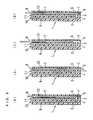
- FIG. 1is a schematic view showing the constitution of a measuring device in accordance with one embodiment of the present invention.
- FIG. 2is an enlarged view of section II-II′′ of FIG. 1 .
- FIG. 3is longitudinal cross-sectional views showing the operation of a puncture member of an analytical element in accordance with one embodiment of the present invention.
- FIG. 4is a longitudinal cross-sectional view of an analytical element in accordance with another embodiment of the present invention from which the reagent layer and surfactant layer are omitted.
- FIG. 5is a longitudinal cross-sectional view of an analytical element in accordance with still another embodiment of the present invention from which the reagent layer and surfactant layer are omitted.
- FIG. 6is a front view of a rod-like member of the same analytical element.
- FIG. 7is a longitudinal cross-sectional view of an analytical element in accordance with still another embodiment of the present invention from which the reagent layer and surfactant layer are omitted.
- FIG. 8is a longitudinal cross-sectional view of an analytical element in accordance with still another embodiment of the present invention.
- FIG. 9is an exploded perspective view of the same analytical element from which the reagent layer and surfactant layer are omitted.
- FIG. 10is a perspective view of an analytical element in accordance with still another embodiment of the present invention.
- FIG. 11is a schematic view showing the constitution of an analytical element and a measuring device in accordance with still another embodiment of the present invention.
- An analytical element in accordance with the present inventioncomprises a cavity for accommodating a sample, a working electrode and a counter electrode exposed to an inside of the cavity, a reagent layer which comprises at least an oxidoreductase and is formed inside or in the vicinity of the cavity, an opening communicating with the cavity and a member covering the opening.
- the openingcan be closed by the member covering the opening after introduction of the sample, the sample inside the cavity is not exposed to the air outside, and it is therefore possible to prevent evaporation of the sample. This particularly leads to an improvement in the measuring accuracy of measurements using a very small amount of sample.
- thisalso prevents scattering of the sample to outside during and after the measurement, and it is therefore possible to provide an analytical element which is hygienically excellent even with the use of an infectious sample such as blood in particular.
- the member covering the opening, when integrated with the analytical element,ensures interception from outside.
- the member covering the openingmay be one covering at least a part of the opening communicating with the cavity for accommodating the sample, but it is preferred to cover the whole opening.
- an element bodycomprising an insulating member is provided with a cavity for accommodating a sample and a working electrode and a counter electrode exposed to the inside of the cavity.
- One end of the cavityserves as a sample supply port while the other end serves as an air vent, and the sample is introduced from the sample supply port into the cavity by capillary action.
- the member covering the opening of the cavitysubstantially closes both of the sample supply port and the air vent.
- the cavitycomprises a depression formed in the element body and a sample supply port and an air vent communicating with the depression.
- the member covering the opening of the cavitymay be one covering merely the inlet side of the depression.
- the material of the member covering the openingmay be any material having a property allowing interception of the outside air so as to suppress evaporation of the sample.
- Such examplesinclude thermoplastic resins such as polyethylene, polystyrene, poly vinyl chloride, polyamide and saturated polyester resin, thermosetting resins such as urea resin, melamine resin, phenol resin, epoxy resin and unsaturated polyester resin, metal such as stainless steel, silver and platinum, or carbon.
- the shape of the member covering the openingis subject to no particular limitation and may be any shape appropriate for the shape of the opening.
- the member covering the openingis preferably a puncture member. This makes it possible to take a sample and measure the sample with the use of just one element, to ensure the use of the sample that has been taken for measurement, and to shorten the time required for taking and measuring the sample. This also makes it possible to downsize the constitution of the analytical element and further reduce the amount of sample necessary for the measurement. Furthermore, this enables reduction in the number of components and the number of manufacturing steps.
- the member covering the openingis preferably transparent. This makes it possible to easily check whether the sample is duly supplied into the analytical element by visual observation.
- the member covering the openingmay also be opaque, and this produces the effect of lessening the fear of a subject particularly in measurements using blood since the sample is invisible from outside.
- the member covering the openingis preferably configured so as to slide on the analytical element body. This allows the subject to manipulate easily.
- the member covering the openingmay be provided with the working electrode or the counter electrode. This makes it possible to downsize the constitution of the analytical element and further reduce the amount of sample necessary for the measurement.
- the member covering the openingmay be provided with the reagent layer. This allows a plurality of reagents to be readily carried while separated from one another within the analytical element; therefore, this realizes high performance and particularly improves the storage stability of the analytical element.
- An analytical element in accordance with a preferred embodiment of the present inventioncomprises: a rod-like element body comprising an insulating member which has a depression for accommodating a sample at its side face in the vicinity of its tip end and a working electrode and a counter electrode arranged so as to be exposed to an inside of the depression; a cover which covers the face of the element body having the depression, the cover having a groove along a longitudinal direction of the element body at a portion facing the depression; and a puncture member which moves in the longitudinal direction of the element body in the groove and sticks out of the tip end of the element body to puncture a subject.
- a sample supply opening communicating with the depressionis formed between the tip end of the element body and the cover.
- An air ventis formed at or above a position of the cover corresponding to the depression.
- the puncture memberis preferably capable of substantially covering the depression.
- the puncture membermay also serve as the working electrode or the counter electrode.
- the element bodymay be provided with the counter electrode or the working electrode.
- Another preferred analytical element in accordance with the present inventioncomprises: an element body comprising an insulating base plate on which an electrode system comprising a working electrode and a counter electrode is formed and a cover member which covers the base plate and forms a sample supply pathway communicating with the electrode system between the cover and the base plate; and a top cover.
- the sample supply pathwayextends from a sample supply port at one end of the element body to an air vent formed in the cover member.
- the top coveris combined to the element body by sliding it in a direction perpendicular to the element body such that it closes the sample supply port and the air vent when it is in close contact with the element body.
- the working electrode and/or the counter electrodemay be provided with the cover member side.
- the reagent layeris formed on the base plate and/or the cover member so as to be exposed to the sample supply pathway.
- a measuring device in accordance with the present inventioncomprises the combination of the above-describe analytical element with voltage application means for applying a voltage between the working electrode and the counter electrode of the analytical element and signal detecting means for detecting an electric signal between the working electrode and the counter electrode upon voltage application, wherein the amount of reaction between a substrate contained in the sample and the oxidoreductase carried on the analytical element is electrochemically detected to quantify the substrate.
- a constitution that the analytical element is separated from the member covering the openingenables reduction in manufacturing cost of the analytical element.
- the member covering the openingis preferably detachable from the analytical element body. This allows only the member covering the opening to be cleaned and makes it possible to provide a measuring device which is hygienically excellent.
- Another preferred measuring device in accordance with the present inventioncomprises: an element body comprising an insulating base plate on which an electrode system comprising a working electrode and a counter electrode is formed and a cover member which covers the base plate and forms a sample supply pathway communicating with the electrode system between the cover and the base plate; and a cylindrical outer cover for fixing the element body therein.
- the sample supply pathway of the element bodyextends from a sample supply port at the tip end of the element body to an air vent formed in the cover member.
- the outer coverhas an air vent communicating with the above-described air vent.
- the measuring devicecomprises: an air vent allowing the air vent of the outer cover to communicate with the air vent of the element body; an inner cover capable of sliding in a longitudinal direction of the outer cover between the outer cover and the element body; a puncture member which sticks out of the inside of the outer cover toward a subject; voltage application means for applying a voltage between the working electrode and the counter electrode of the analytical element; and signal detecting means for detecting an electric signal between the working electrode and the counter electrode upon voltage application.
- the measuring devicefurther comprises needle driving means for driving the puncture member, needle position controlling means for controlling needle position, inner cover driving means for driving the inner cover, and inner cover position controlling means for controlling inner cover position.
- the inner coveris, until a sample is taken, at a position at which the sample supply port and the air vent of the element body are open. After the sample is taken from the sample supply port, the inner cover moves inside the outer cover toward its tip end to block the air vent of the outer cover and the air vent of the element body, and the front end portion of the inner cover bends to close the sample supply port.
- a substrate quantification method in accordance with the present inventioncomprises the steps of: preparing the above-described analytical element; supplying the sample to the analytical element to react a substrate contained in the sample with the oxidoreductase of the analytical element; closing the opening of the analytical element; applying a voltage between the working electrode and the counter electrode; and detecting a change in electric signal between the working electrode and the counter electrode upon the voltage application.
- the voltageis generally applied between the working electrode and the counter electrode so as to make the working electrode positive. This oxidizes the reduced form electron mediator resulting from the enzyme reaction on the working electrode.
- the change of electric signal between the working electrode and the counter electrodeis detected as the amount of this oxidation current of the electron mediator. On the basis of this amount of current, the substrate concentration of the sample can be obtained. Instead of the measured value of this current, the value obtained by converting the current into voltage may be displayed.
- the sample inside the cavity of the analytical elementis not exposed to the outside air, evaporation of the sample is prevented and the measuring accuracy is improved particularly in the case of measurements using a very small amount of sample. Further, since the sample is prevented from scattering to outside during and after the measurement, it is hygienically excellent even with the use of an infectious sample such as blood in particular.
- a conductive material which is not subject to oxidation upon oxidation of the electron mediatoris used.
- a commonly used conductive materialsuch as palladium, gold, platinum or carbon may be used.
- the surface of an electrically insulating materialmay be coated with such a conductive material.
- oxidorecuctaseone adequate for the substrate contained in the sample to be measured may be used.
- Such examplesinclude fructose dehydrogenase, glucose oxidase, glucose dehydrogenase, alcohol oxidase, lactate oxidase, cholesterol oxidase, xanthine oxidase, amino acid oxidase, etc.
- the puncture membermay be any member having enough strength for puncture, and such examples include a needle composed of metal, such as stainless steel, gold or platinum, or carbon.
- a conductive materialsuch as gold, platinum or carbon may be used, or the surface of an insulating material may be coated with such a conductive material.
- the analytical element of the present inventionis designed for measuring samples which are solutions containing various kinds of substrates and body fluids of which sampling amount is required to be reduced further.
- the body fluidsinclude whole blood, plasma, serum, interstitial fluid and saliva. These examples are not to be construed as limiting the samples to be measured by the present invention.
- FIG. 1is a schematic view of a measuring device used in this example and is a longitudinal cross-sectional view of an analytical element from which the reagent layer and surfactant layer are omitted.
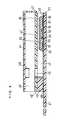
- FIG. 3is a longitudinal cross-sectional view showing the operation of a puncture member in the analytical element
- FIGS. 4 to 5are longitudinal cross-sectional views showing other forms of electrodes in the analytical element of this example from which the regent layer and surfactant layer are omitted.
- the measuring device as shown in FIG. 1is composed of an analytical element 1 and a main body 20 .
- the analytical element 1is composed of a puncture member 6 , a rod-like member 8 and a cover 7 .
- the rod-like member 8comprises a cavity 4 for accommodating a sample, a working electrode 2 and a counter electrode 3 exposed to the inside of the cavity 4 , and a reagent layer (not shown in the figure) carried inside the cavity 4 .
- the cover 7is joined to the rod-like member 8 so as to cover its cavity 4 side and has a groove 12 for guiding the puncture member 6 and an air vent 5 that is open in the vicinity of the cavity 4 .
- the groove 12has, at its lower part, an opening which serves as a sample supply port 9 from which the sample is introduced into the cavity 4 by capillary action.
- the opening of the cavity 4is substantially closed by the puncture member 6 in a state as shown in FIG. 1 .
- a working electrode lead 10 composed of a 30 mm long conductive material and a counter electrode lead 11 composed of a 29 mm long conductive materialare embedded in the rod-like member 8 by insert-molding a synthetic resin which is electrically insulating.
- a section of these conductive membersis a rectangle of 0.5 mm ⁇ 1 mm.
- the tip ends of the leads 10 and 11 exposed to the inside of the cavity 4serve as the working electrode 2 and the counter electrode 3 , respectively.
- the cavity 4has a size of 1 mm ⁇ 1 mm ⁇ 1 mm.
- the puncture member 6is a column having a diameter of 1.0 mm and a length of 40 mm.
- aqueous solution containing GOD as an oxidoreductase and potassium ferricyanide as an electron mediatoris dropped into the cavity 4 and is then dried to form a reagent layer. Further, for the purpose of facilitating smooth supply of the sample, a surfactant layer containing lecithin as a surfactant is formed over the reagent layer and from the cavity 4 up to the sample supply port 9 .
- the cover 7is bonded to the rod-like member 8 , on which the reagent layer and the surfactant layer are formed in the above manner, in such a manner as to accommodate the puncture member 6 therein to fabricate the analytical element 1 .
- the main body 20comprises a voltage application unit 21 for applying a constant voltage between the working electrode 2 and the counter electrode 3 of the analytical element 1 , a current detection unit 22 for detecting a current flowing between the working electrode 2 and the counter electrode 3 , a driving unit 24 for driving the puncture member 6 vertically, and a position controlling unit 25 for controlling the position of the puncture member 6 .
- the puncture member 6is connected via a holder 23 to the driving unit 24 .
- the working electrode lead 10 and the counter electrode lead 11are connected to the voltage application unit 21 and the current detection unit 22 , respectively.
- the concentration of ⁇ -D-glucose in sample solutionswas quantified.
- several kinds of sample solutions having different ⁇ -D-glucose concentrationswere prepared.
- the puncture member 6was moved to a position at which it did not close the air vent 5 and the sample supply port 9 as shown in FIG. 3 ( c ), and a sample solution was then brought in contact with the sample supply port 9 . Since the air vent 5 communicated with the cavity 4 , the sample solution introduced to the sample supply port 9 was permeated by capillary action and supplied into the cavity 4 . Thereafter, while the puncture member 6 was held at the position as shown in FIG.
- the response obtainedwas one which shifted from the measurement value obtained at the humidity of 100% toward the positive side when the position of the puncture member 6 was held as shown in FIG. 3 ( c ).
- the response obtainedwas in good agreement with the measurement value obtained at the humidity of 100%. This is presumably because the puncture member 6 was able to suppress the evaporation of the sample solution inside the sample supply section 4 during the measurement.
- the puncture member 6is set at the position as shown in FIG. 3 ( a ), and the analytical element 1 is then pressed against a subject such that the sample supply port 9 comes in contact with the skin.
- the skin of the subjectis punctured by the puncture member 6 . This causes a body fluid to leak from the skin.
- the puncture member 6is moved to a position at which the air vent 5 is open, and is fixed at the position; this causes the body fluid to be introduced into the sample supply section 4 .
- the puncture member 6After a lapse of certain time from the puncture, as shown in FIG. 3 ( d ), the puncture member 6 is moved to a position at which the puncture member 6 closes the air vent 5 and the sample supply port 9 and its tip end does not stick out of the sample supply port 9 to outside the analytical element 1 . Subsequently, a voltage of 500 mV is applied to the working electrode 2 with respect to the counter electrode 3 by the voltage application unit 21 , and the value of the current flowing through the working electrode 2 is then detected by the current detection unit 22 to measure the concentration of the substrate in the body fluid.
- the layout of the working electrode 2 and the counter electrode 3is not limited to that as shown in FIG. 1 .
- itmay be such a layout as shown in FIG. 4 in which the working electrode 2 and the counter electrode 3 are arranged at opposite sides of the cavity 4 .
- Such a layoutallows the current density of the electrode surface to be more uniform, leading to an improvement in measuring sensitivity.
- the layoutmay be as shown in FIG. 5 and FIG. 6 in which the working electrode 2 and the counter electrode 3 are arranged on the same plane.
- the above-mentioned rod-like member 8is formed by combining members 8 a and 8 b composed of an electrically insulating synthetic resin.
- the method of producing this analytical elementwill be explained: first, two pieces of noble metal such as palladium foil, i.e., a working electrode 2 b and its lead 10 b and a counter electrode 3 b and its lead 11 b , are attached to the surface of the member 8 a .
- the member 8 a having the electrodes and leads formed thereonis combined to the member 8 b having a hole for forming the cavity 4 .
- a cover 7which is the same as that described above is joined to the resultant rod-like member having the electrodes 2 b and 3 b formed on the same plane, to complete the analytical element.
- electrodesmay be formed by sputtering noble metal such as palladium on the surface of the member 8 a to form a conductive layer and trimming the conductive layer by laser so as to substantially separate the working electrode and its lead and the counter electrode and its lead from one another. This enables concurrent formation of the working electrode 2 and the counter electrode 3 and therefore facilitates the manufacturing.
- noble metalsuch as palladium
- the puncture member 6composed of a conductive material may also serve as the counter electrode 3 . This reduces the number of parts and therefore enables size reduction, so that further reduction is possible in the amount of sample necessary for the measurement.
- FIG. 8is a longitudinal cross-sectional view of the analytical element of this example
- FIG. 9is an exploded perspective view of the same analytical element from which the reagent layer and surfactant layer are omitted.
- a silver pasteis printed on an electrically insulating base plate 31 made of polyethylene terephthalate by screen printing to form a working electrode lead 32 and a counter electrode lead 33 .
- a conductive carbon paste containing a resin binderis printed on the base plate 31 to form a working electrode 34 .
- the working electrode 34is in contact with the working electrode lead 32 .
- an insulating pasteis printed on the base plate 31 to form an insulating layer 36 .
- the insulating layer 36covers the outer periphery of the working electrode 34 so as to keep the exposed area of the working electrode 34 constant.
- a conductive carbon paste containing a resin binderis printed on the base plate 31 so as to be in contact with the counter electrode lead 33 , thereby to form a counter electrode 35 .
- aqueous solution containing GOD as the oxidoreductase and potassium ferricyanide as the electron mediatoris dropped over the working electrode 34 and the counter electrode 35 and is then dried to form a reagent layer 38 .
- a surfactant layer 39containing lecithin as the surfactant.
- the base plate 31 , a mid cover 42 having an air vent 45 , and a spacer member 40are bonded to one another in a positional relationship as shown by the dashed lines in FIG. 9 .
- the spacer member 40 to be interposed between the base plate 31 and the mid cover 42has a slit 41 , and the slit 41 forms a sample supply pathway between the base plate 31 and the mid cover 42 .
- the air vent 45 of the mid cover 42communicates with the sample supply pathway; thus, when a sample is brought in contact with a sample supply port 49 formed at an open end of the slit 41 , the sample readily reaches the surfactant layer 39 and the reagent layer 38 in the sample supply pathway by capillary action.
- top cover 44is mounted.
- the top cover 44has a suspended part 46 which hangs down at its circumference excluding the rear end.
- the suspended part 46has a protruding piece 47 which is to engage with a protruding piece 37 formed on the base plate 31 and protrusions which are to fit into indentations 50 formed in the base plate.
- the top cover 44further has a cylindrical part 48 which is to fit into the air vent 45 of the mid cover 42 .
- the top cover 44is capable of moving perpendicularly to the electrode-printed surface of the assembly of the base plate 31 , the spacer member 40 and the mid cover 42 .
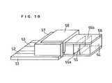
- FIG. 10is a perspective view of an analytical element used in this example.
- the analytical element of this exampleis composed of a base plate 51 having the same constitution as that of the base plate 31 of Example 2, a spacer 54 , a mid cover 56 covering the spacer, a top cover 58 , and a stopper 57 .
- the spacer 54has an depression 55 which is open at its both sides and bottom face, and the depression forms a cavity for accommodating a sample in combination with the base plate 51 .
- the depression 55 of the spacerhas openings 55 a and 55 b at its sides, and one of the openings serves as the sample supply port and the other serves as the air vent.
- the base plate 51has a working electrode and a counter electrode connected to leads 52 and 53 , respectively. These electrodes are exposed to the depression 55 of the spacer 54 .
- the top cover 58moves in parallel with the electrode-printed surface of the base plate 51 along grooves formed in the stopper 57 .
- the top cover 58is slid to close the openings at both sides of the depression 55 , and this can prevent evaporation of the sample solution. In this way, in the analytical element of this example, the similar effects to those of Example 1 can also be obtained. Further, since the top cover 58 is hidden in the stopper 57 , it is possible to obtain the effect of preventing a sample such as blood from adhering to an outer surface of the top cover 58 .
- Examples 2 and 3have described a constitution that the electrode system is arranged on the base plate, i.e., on the same plane, but this is not to be construed as limiting the constitution.
- a constitution of an opposed-type electrode systemsuch as a constitution that the electrodes are arranged so as to face each other may also be employed.
- the working electrodemay be arranged on the base plate 31 and the counter electrode may be arranged on the underside of the mid cover 42 .
- the shape of the top coveris not limited to the shape as shown in the figure and may be any shape capable of producing the effect of closing the sample supply port and air vent.
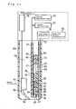
- FIG. 11is a schematic view showing the constitution of an analytical element and a measuring device used in this example.
- the analytical element 70 of this examplehas the same structure as that of the analytical element used in Example 2 except for the absence of the top cover which is a member covering the opening.
- the measuring devicecomprises a voltage application unit 71 , a current detection unit 72 , a needle 76 detachably mounted to a holder 79 , a needle driving unit 77 , a needle position controlling unit 78 , a first inner cover 62 , a connecting part 73 for connecting the inner cover 62 to an inner cover driving unit 74 , a second inner cover 64 pivotally mounted to the tip end of the first inner cover 62 , the inner cover driving unit 74 , an inner cover position controlling unit 75 , and an outer cover 60 .
- the analytical element 70is mounted to the measuring device and fixed inside the outer cover 60 as shown in FIG. 11 .
- the first inner cover 62 and the outer cover 60 of the measuring devicehave an air vent 63 and an air vent 61 , respectively, at a position facing the air vent 45 of the analytical element when the analytical element 70 is mounted to the measuring device.
- the second inner cover 64can bend with a pivotal joint 65 with the first inner cover 62 as the pivot.
- the first inner cover 62 and the second inner cover 64are pushed toward the opening of the outer cover 60 .
- the second inner cover 64comes in contact with the opening edge of the outer cover 60 which extends inward.
- the second inner cover 64bends at the pivotal joint 65 so as to cover the sample supply port 49 of the analytical element 70 .
- the first inner cover 62blocks the air vent 45 of the analytical element 70 and the air vent 61 of the outer cover 60 . In this way, since the sample supply port 49 and the air vent 45 of the analytical element are substantially blocked by the inner cover mounted to the measuring device, it is possible to prevent evaporation of the sample during the measurement.
- the inner coverconsisting of the first inner cover 62 , the pivotal joint 65 and the second inner cover 64 is detachable and can therefore be cleaned easily, it is possible to provide a hygienic measuring device. Further, since the needle 76 for taking a sample is mounted inside the measuring device, an extremely small amount of sample can be introduced into the analytical element in a reliable manner; furthermore, since the inner cover prevents evaporation of the sample, reduction of the sample is possible.
- FIG. 11is just an example, and it is also possible to employ a constitution that the needle, holder, needle driving unit and needle position controlling unit are not included in the measuring device. Also, the position of the air vents 63 and 61 is not limited to the position as shown in FIG. 11 and may be adjusted appropriately depending on the shape of the analytical element.
- the position of the air vent in the analytical elementis not limited to the position as shown in the figure and may be any position if the air vent communicates with the cavity for accommodating the sample and is opposite the sample supply port side of the cavity.
- a solution containing an oxidoreductasewas applied and dried to form the reagent layer; however, there is no limitation thereto, and a solution containing a reagent may be applied into the cavity by an ink jet method, for example. This enables precise position control in application of a very small amount of sample.
- a solution containing a reagentmay be impregnated into a glass filter paper and dried so as to cause the glass filter paper to carry the reagent, and the resultant paper may be placed into the cavity.
- the position of the reagent carriedis preferably on the electrode, but this is not to be construed as limiting the position, and the reagent may be positioned at other parts of the cavity than the electrode if it is capable of coming in contact with the sample.
- the working electrode, the counter electrode, and their leadsit is possible in the present invention to employ a method in which a conductive material in the form of a wire, foil or the like is molded with an insulating synthetic resin, a method in which a conductive paste is printed on an insulating supporting material, and a method in which a conductive layer is formed on an insulating supporting material by sputtering and is divided into a working electrode and a counter electrode by laser trimming or the like.
- thermoplastic resinssuch as polyethylene, polystyrene, poly vinyl chloride, polyamide and saturated polyester resin
- thermosetting resinssuch as urea resin, melamine resin, phenol resin, epoxy resin and unsaturated polyester resin.
- polyethylene terephthalateis preferable in terms of the adhesion to the electrode.
- thermoplastic resinssuch as polyethylene, polystyrene, poly vinyl chloride, polyamide and saturated polyester resin
- thermosetting resinssuch as urea resin, melamine resin, phenol resin, epoxy resin and unsaturated polyester resin.
- An elastic materialsuch as an O-ring may be preferably provided at a contacting portion of the member covering the opening with the analytical element, so that the adhesion of the member covering the opening to the analytical element is enhanced to improve the effect of preventing the evaporation of the sample.
- the electron mediatorexamples include potassium ferricyanide, p-benzoquinone, phenazine methosulfate, methylene blue, and ferrocene derivatives. Also, even when oxygen is used as the electron mediator, current response is obtained. These electron mediators are used singly or in combination of two or more.
- the present inventioncan provide an analytical element which can prevent evaporation of a sample during measurement and therefore quantify a substrate using a very small amount of sample with high accuracy and which can prevent scattering of the sample during and after the measurement and is therefore hygienically excellent; and a measuring device and a substrate quantification method using this analytical element.
Landscapes
- Health & Medical Sciences (AREA)
- Life Sciences & Earth Sciences (AREA)
- Engineering & Computer Science (AREA)
- Physics & Mathematics (AREA)
- Molecular Biology (AREA)
- Biophysics (AREA)
- General Health & Medical Sciences (AREA)
- Pathology (AREA)
- Heart & Thoracic Surgery (AREA)
- Medical Informatics (AREA)
- Surgery (AREA)
- Animal Behavior & Ethology (AREA)
- Biomedical Technology (AREA)
- Public Health (AREA)
- Veterinary Medicine (AREA)
- Hematology (AREA)
- Chemical & Material Sciences (AREA)
- Organic Chemistry (AREA)
- Manufacturing & Machinery (AREA)
- Chemical Kinetics & Catalysis (AREA)
- Analytical Chemistry (AREA)
- Immunology (AREA)
- Biochemistry (AREA)
- Proteomics, Peptides & Aminoacids (AREA)
- Wood Science & Technology (AREA)
- Zoology (AREA)
- General Physics & Mathematics (AREA)
- Dermatology (AREA)
- General Engineering & Computer Science (AREA)
- Genetics & Genomics (AREA)
- Biotechnology (AREA)
- Electrochemistry (AREA)
- Bioinformatics & Cheminformatics (AREA)
- General Chemical & Material Sciences (AREA)
- Microbiology (AREA)
- Optics & Photonics (AREA)
- Investigating Or Analysing Biological Materials (AREA)
- Apparatus Associated With Microorganisms And Enzymes (AREA)
- Measuring Or Testing Involving Enzymes Or Micro-Organisms (AREA)
- Investigating Or Analysing Materials By The Use Of Chemical Reactions (AREA)
Abstract
Description
Claims (20)
Applications Claiming Priority (3)
| Application Number | Priority Date | Filing Date | Title |
|---|---|---|---|
| JP2000-378323 | 2000-12-13 | ||
| JP2000378323 | 2000-12-13 | ||
| PCT/JP2001/010866WO2002048703A1 (en) | 2000-12-13 | 2001-12-11 | Analytical element, and measuring instrument and substrate determining method using the same |
Related Parent Applications (1)
| Application Number | Title | Priority Date | Filing Date |
|---|---|---|---|
| PCT/JP2001/010866ContinuationWO2002048703A1 (en) | 2000-12-13 | 2001-12-11 | Analytical element, and measuring instrument and substrate determining method using the same |
Publications (2)
| Publication Number | Publication Date |
|---|---|
| US20030003524A1 US20030003524A1 (en) | 2003-01-02 |
| US6878262B2true US6878262B2 (en) | 2005-04-12 |
Family
ID=18846913
Family Applications (1)
| Application Number | Title | Priority Date | Filing Date |
|---|---|---|---|
| US10/216,716Expired - LifetimeUS6878262B2 (en) | 2000-12-13 | 2002-08-13 | Analytical element and measuring device and substrate quantification method using the same |
Country Status (6)
| Country | Link |
|---|---|
| US (1) | US6878262B2 (en) |
| EP (1) | EP1262768B1 (en) |
| JP (1) | JP3677500B2 (en) |
| CN (1) | CN1209621C (en) |
| ES (1) | ES2382367T3 (en) |
| WO (1) | WO2002048703A1 (en) |
Cited By (67)
| Publication number | Priority date | Publication date | Assignee | Title |
|---|---|---|---|---|
| US20040242982A1 (en)* | 2001-09-11 | 2004-12-02 | Tetsuya Sakata | Measuring instrument, installation body, and density measurer |
| US20070238943A1 (en)* | 2006-04-07 | 2007-10-11 | Radiometer Medical Aps | Mounting device for an electrochemical sensor unit |
| US7297151B2 (en) | 2002-04-19 | 2007-11-20 | Elikan Technologies, Inc. | Method and apparatus for body fluid sampling with improved sensing |
| US7316700B2 (en) | 2001-06-12 | 2008-01-08 | Pelikan Technologies, Inc. | Self optimizing lancing device with adaptation means to temporal variations in cutaneous properties |
| US7344507B2 (en) | 2002-04-19 | 2008-03-18 | Pelikan Technologies, Inc. | Method and apparatus for lancet actuation |
| US7344894B2 (en) | 2001-10-16 | 2008-03-18 | Agilent Technologies, Inc. | Thermal regulation of fluidic samples within a diagnostic cartridge |
| US7374544B2 (en) | 2002-04-19 | 2008-05-20 | Pelikan Technologies, Inc. | Method and apparatus for penetrating tissue |
| US7410468B2 (en) | 2002-04-19 | 2008-08-12 | Pelikan Technologies, Inc. | Method and apparatus for penetrating tissue |
| US7481776B2 (en) | 2002-04-19 | 2009-01-27 | Pelikan Technologies, Inc. | Method and apparatus for penetrating tissue |
| US20090026074A1 (en)* | 2007-07-26 | 2009-01-29 | Sridhar Iyengar | Electrochemical test strips |
| US7491178B2 (en) | 2002-04-19 | 2009-02-17 | Pelikan Technologies, Inc. | Method and apparatus for penetrating tissue |
| US7524293B2 (en) | 2002-04-19 | 2009-04-28 | Pelikan Technologies, Inc. | Method and apparatus for penetrating tissue |
| US7537571B2 (en) | 2001-06-12 | 2009-05-26 | Pelikan Technologies, Inc. | Integrated blood sampling analysis system with multi-use sampling module |
| US7547287B2 (en) | 2002-04-19 | 2009-06-16 | Pelikan Technologies, Inc. | Method and apparatus for penetrating tissue |
| US7563232B2 (en) | 2002-04-19 | 2009-07-21 | Pelikan Technologies, Inc. | Method and apparatus for penetrating tissue |
| US7582099B2 (en) | 2002-04-19 | 2009-09-01 | Pelikan Technologies, Inc | Method and apparatus for penetrating tissue |
| US7582063B2 (en) | 2000-11-21 | 2009-09-01 | Pelikan Technologies, Inc. | Blood testing apparatus having a rotatable cartridge with multiple lancing elements and testing means |
| US7604592B2 (en) | 2003-06-13 | 2009-10-20 | Pelikan Technologies, Inc. | Method and apparatus for a point of care device |
| US7648468B2 (en) | 2002-04-19 | 2010-01-19 | Pelikon Technologies, Inc. | Method and apparatus for penetrating tissue |
| US7666149B2 (en) | 1997-12-04 | 2010-02-23 | Peliken Technologies, Inc. | Cassette of lancet cartridges for sampling blood |
| US7674232B2 (en) | 2002-04-19 | 2010-03-09 | Pelikan Technologies, Inc. | Method and apparatus for penetrating tissue |
| US7682318B2 (en) | 2001-06-12 | 2010-03-23 | Pelikan Technologies, Inc. | Blood sampling apparatus and method |
| US7699791B2 (en) | 2001-06-12 | 2010-04-20 | Pelikan Technologies, Inc. | Method and apparatus for improving success rate of blood yield from a fingerstick |
| US7713214B2 (en) | 2002-04-19 | 2010-05-11 | Pelikan Technologies, Inc. | Method and apparatus for a multi-use body fluid sampling device with optical analyte sensing |
| US7717863B2 (en) | 2002-04-19 | 2010-05-18 | Pelikan Technologies, Inc. | Method and apparatus for penetrating tissue |
| US7731729B2 (en) | 2002-04-19 | 2010-06-08 | Pelikan Technologies, Inc. | Method and apparatus for penetrating tissue |
| US7822454B1 (en) | 2005-01-03 | 2010-10-26 | Pelikan Technologies, Inc. | Fluid sampling device with improved analyte detecting member configuration |
| US7833171B2 (en) | 2002-04-19 | 2010-11-16 | Pelikan Technologies, Inc. | Method and apparatus for penetrating tissue |
| US7841992B2 (en) | 2001-06-12 | 2010-11-30 | Pelikan Technologies, Inc. | Tissue penetration device |
| US7850621B2 (en) | 2003-06-06 | 2010-12-14 | Pelikan Technologies, Inc. | Method and apparatus for body fluid sampling and analyte sensing |
| US7862520B2 (en) | 2002-04-19 | 2011-01-04 | Pelikan Technologies, Inc. | Body fluid sampling module with a continuous compression tissue interface surface |
| US7874994B2 (en) | 2002-04-19 | 2011-01-25 | Pelikan Technologies, Inc. | Method and apparatus for penetrating tissue |
| US7892183B2 (en) | 2002-04-19 | 2011-02-22 | Pelikan Technologies, Inc. | Method and apparatus for body fluid sampling and analyte sensing |
| US7901362B2 (en) | 2002-04-19 | 2011-03-08 | Pelikan Technologies, Inc. | Method and apparatus for penetrating tissue |
| US7909778B2 (en) | 2002-04-19 | 2011-03-22 | Pelikan Technologies, Inc. | Method and apparatus for penetrating tissue |
| US7909775B2 (en) | 2001-06-12 | 2011-03-22 | Pelikan Technologies, Inc. | Method and apparatus for lancet launching device integrated onto a blood-sampling cartridge |
| US7914465B2 (en) | 2002-04-19 | 2011-03-29 | Pelikan Technologies, Inc. | Method and apparatus for penetrating tissue |
| US20110125059A1 (en)* | 2008-01-28 | 2011-05-26 | Wolfgang Petrich | Blood glucose measurement for small blood volume |
| US7959582B2 (en) | 2002-04-19 | 2011-06-14 | Pelikan Technologies, Inc. | Method and apparatus for penetrating tissue |
| US7976476B2 (en) | 2002-04-19 | 2011-07-12 | Pelikan Technologies, Inc. | Device and method for variable speed lancet |
| US8197421B2 (en) | 2002-04-19 | 2012-06-12 | Pelikan Technologies, Inc. | Method and apparatus for penetrating tissue |
| US8221334B2 (en) | 2002-04-19 | 2012-07-17 | Sanofi-Aventis Deutschland Gmbh | Method and apparatus for penetrating tissue |
| US8267870B2 (en) | 2002-04-19 | 2012-09-18 | Sanofi-Aventis Deutschland Gmbh | Method and apparatus for body fluid sampling with hybrid actuation |
| US8282576B2 (en) | 2003-09-29 | 2012-10-09 | Sanofi-Aventis Deutschland Gmbh | Method and apparatus for an improved sample capture device |
| US8333710B2 (en) | 2002-04-19 | 2012-12-18 | Sanofi-Aventis Deutschland Gmbh | Tissue penetration device |
| US8435190B2 (en) | 2002-04-19 | 2013-05-07 | Sanofi-Aventis Deutschland Gmbh | Method and apparatus for penetrating tissue |
| US8439872B2 (en) | 1998-03-30 | 2013-05-14 | Sanofi-Aventis Deutschland Gmbh | Apparatus and method for penetration with shaft having a sensor for sensing penetration depth |
| US8652831B2 (en) | 2004-12-30 | 2014-02-18 | Sanofi-Aventis Deutschland Gmbh | Method and apparatus for analyte measurement test time |
| US8668656B2 (en) | 2003-12-31 | 2014-03-11 | Sanofi-Aventis Deutschland Gmbh | Method and apparatus for improving fluidic flow and sample capture |
| US8702624B2 (en) | 2006-09-29 | 2014-04-22 | Sanofi-Aventis Deutschland Gmbh | Analyte measurement device with a single shot actuator |
| US8721671B2 (en) | 2001-06-12 | 2014-05-13 | Sanofi-Aventis Deutschland Gmbh | Electric lancet actuator |
| US8828203B2 (en) | 2004-05-20 | 2014-09-09 | Sanofi-Aventis Deutschland Gmbh | Printable hydrogels for biosensors |
| US8965476B2 (en) | 2010-04-16 | 2015-02-24 | Sanofi-Aventis Deutschland Gmbh | Tissue penetration device |
| US9034639B2 (en) | 2002-12-30 | 2015-05-19 | Sanofi-Aventis Deutschland Gmbh | Method and apparatus using optical techniques to measure analyte levels |
| US9072842B2 (en) | 2002-04-19 | 2015-07-07 | Sanofi-Aventis Deutschland Gmbh | Method and apparatus for penetrating tissue |
| US9144401B2 (en) | 2003-06-11 | 2015-09-29 | Sanofi-Aventis Deutschland Gmbh | Low pain penetrating member |
| US9226699B2 (en) | 2002-04-19 | 2016-01-05 | Sanofi-Aventis Deutschland Gmbh | Body fluid sampling module with a continuous compression tissue interface surface |
| US9248267B2 (en) | 2002-04-19 | 2016-02-02 | Sanofi-Aventis Deustchland Gmbh | Tissue penetration device |
| US9314194B2 (en) | 2002-04-19 | 2016-04-19 | Sanofi-Aventis Deutschland Gmbh | Tissue penetration device |
| US9351680B2 (en) | 2003-10-14 | 2016-05-31 | Sanofi-Aventis Deutschland Gmbh | Method and apparatus for a variable user interface |
| US9375169B2 (en) | 2009-01-30 | 2016-06-28 | Sanofi-Aventis Deutschland Gmbh | Cam drive for managing disposable penetrating member actions with a single motor and motor and control system |
| US9386944B2 (en) | 2008-04-11 | 2016-07-12 | Sanofi-Aventis Deutschland Gmbh | Method and apparatus for analyte detecting device |
| US9427532B2 (en) | 2001-06-12 | 2016-08-30 | Sanofi-Aventis Deutschland Gmbh | Tissue penetration device |
| US9560993B2 (en) | 2001-11-21 | 2017-02-07 | Sanofi-Aventis Deutschland Gmbh | Blood testing apparatus having a rotatable cartridge with multiple lancing elements and testing means |
| US9795747B2 (en) | 2010-06-02 | 2017-10-24 | Sanofi-Aventis Deutschland Gmbh | Methods and apparatus for lancet actuation |
| US9820684B2 (en) | 2004-06-03 | 2017-11-21 | Sanofi-Aventis Deutschland Gmbh | Method and apparatus for a fluid sampling device |
| US9839386B2 (en) | 2002-04-19 | 2017-12-12 | Sanofi-Aventis Deustschland Gmbh | Body fluid sampling device with capacitive sensor |
Families Citing this family (33)
| Publication number | Priority date | Publication date | Assignee | Title |
|---|---|---|---|---|
| ITMI20011231A1 (en) | 2001-06-12 | 2002-12-12 | St Microelectronics Srl | CIRCUITERIA OF DETECTION FOR READING AND VERIFYING THE CONTENT OF ELECTRONIC NON-VOLATILE MEMORY CELLS AND ELECTRIC |
| US8260393B2 (en) | 2003-07-25 | 2012-09-04 | Dexcom, Inc. | Systems and methods for replacing signal data artifacts in a glucose sensor data stream |
| US8010174B2 (en) | 2003-08-22 | 2011-08-30 | Dexcom, Inc. | Systems and methods for replacing signal artifacts in a glucose sensor data stream |
| US20190357827A1 (en) | 2003-08-01 | 2019-11-28 | Dexcom, Inc. | Analyte sensor |
| US20080119703A1 (en) | 2006-10-04 | 2008-05-22 | Mark Brister | Analyte sensor |
| US7920906B2 (en) | 2005-03-10 | 2011-04-05 | Dexcom, Inc. | System and methods for processing analyte sensor data for sensor calibration |
| US20140121989A1 (en) | 2003-08-22 | 2014-05-01 | Dexcom, Inc. | Systems and methods for processing analyte sensor data |
| US9247900B2 (en) | 2004-07-13 | 2016-02-02 | Dexcom, Inc. | Analyte sensor |
| ATE480761T1 (en)* | 2003-12-05 | 2010-09-15 | Dexcom Inc | CALIBRATION METHODS FOR A CONTINUOUSLY WORKING ANALYTICAL SENSOR |
| US20100185071A1 (en)* | 2003-12-05 | 2010-07-22 | Dexcom, Inc. | Dual electrode system for a continuous analyte sensor |
| US8423114B2 (en)* | 2006-10-04 | 2013-04-16 | Dexcom, Inc. | Dual electrode system for a continuous analyte sensor |
| US11633133B2 (en) | 2003-12-05 | 2023-04-25 | Dexcom, Inc. | Dual electrode system for a continuous analyte sensor |
| US8287453B2 (en)* | 2003-12-05 | 2012-10-16 | Dexcom, Inc. | Analyte sensor |
| US8364231B2 (en) | 2006-10-04 | 2013-01-29 | Dexcom, Inc. | Analyte sensor |
| EP2301428B1 (en) | 2003-12-09 | 2016-11-30 | Dexcom, Inc. | Signal processing for continuous analyte sensor |
| US7654956B2 (en) | 2004-07-13 | 2010-02-02 | Dexcom, Inc. | Transcutaneous analyte sensor |
| JP2009507224A (en) | 2005-08-31 | 2009-02-19 | ユニヴァーシティー オブ ヴァージニア パテント ファンデーション | Improving the accuracy of continuous glucose sensors |
| US9675290B2 (en) | 2012-10-30 | 2017-06-13 | Abbott Diabetes Care Inc. | Sensitivity calibration of in vivo sensors used to measure analyte concentration |
| US8219173B2 (en) | 2008-09-30 | 2012-07-10 | Abbott Diabetes Care Inc. | Optimizing analyte sensor calibration |
| US7653425B2 (en) | 2006-08-09 | 2010-01-26 | Abbott Diabetes Care Inc. | Method and system for providing calibration of an analyte sensor in an analyte monitoring system |
| US8224415B2 (en) | 2009-01-29 | 2012-07-17 | Abbott Diabetes Care Inc. | Method and device for providing offset model based calibration for analyte sensor |
| JP2008003066A (en)* | 2006-06-26 | 2008-01-10 | Sumitomo Electric Ind Ltd | Biosensor cartridge |
| US8239166B2 (en) | 2007-05-14 | 2012-08-07 | Abbott Diabetes Care Inc. | Method and apparatus for providing data processing and control in a medical communication system |
| DK3689237T3 (en) | 2009-07-23 | 2021-08-16 | Abbott Diabetes Care Inc | Method of preparation and system for continuous analyte measurement |
| US9314195B2 (en) | 2009-08-31 | 2016-04-19 | Abbott Diabetes Care Inc. | Analyte signal processing device and methods |
| US8529742B2 (en)* | 2010-02-24 | 2013-09-10 | Matthew K. Musho | Electrochemical sensor with controlled variation of working electrode |
| EP2697650B1 (en) | 2011-04-15 | 2020-09-30 | Dexcom, Inc. | Advanced analyte sensor calibration and error detection |
| WO2014052136A1 (en) | 2012-09-26 | 2014-04-03 | Abbott Diabetes Care Inc. | Method and apparatus for improving lag correction during in vivo measurement of analyte concentration with analyte concentration variability and range data |
| US10898116B2 (en)* | 2013-03-15 | 2021-01-26 | Cambridge Medical Technologies LLC | Methods of manufacture to optimize performance of transdermal sampling and analysis device |
| EP3618712A1 (en) | 2017-05-03 | 2020-03-11 | Abbott Diabetes Care Inc. | Systems, devices, and methods with duration-based adjustment of sensor data |
| EP4218568A1 (en) | 2017-08-18 | 2023-08-02 | Abbott Diabetes Care Inc. | Analyte monitoring system storing a measured electrical characteristic of the in vivo analyte sensor of the system as individualized calibration information |
| US11633129B2 (en) | 2019-04-05 | 2023-04-25 | Cambridge Medical Technologies LLC | Non-invasive transdermal sampling and analysis device incorporating redox cofactors |
| US11375931B2 (en) | 2019-08-08 | 2022-07-05 | Cambridge Medical Technologies LLC | Non-invasive transdermal sampling and analysis device incorporating an electrochemical bioassay |
Citations (17)
| Publication number | Priority date | Publication date | Assignee | Title |
|---|---|---|---|---|
| JPS61115964A (en) | 1984-11-09 | 1986-06-03 | Nippon Kokan Kk <Nkk> | Carbon black manufacturing method using metal bath method |
| JPH03202764A (en) | 1989-09-21 | 1991-09-04 | Matsushita Electric Ind Co Ltd | Biosensor and its manufacturing method |
| JPH03237349A (en) | 1990-02-14 | 1991-10-23 | Omron Corp | Biochemical measuring instrument |
| JPH04194660A (en) | 1990-11-27 | 1992-07-14 | Omron Corp | Device for measuring concentration of component in blood |
| JPH06213843A (en) | 1993-01-19 | 1994-08-05 | Daikin Ind Ltd | Microorganism detection instrument |
| JPH07159366A (en)* | 1993-12-07 | 1995-06-23 | Omron Corp | Portable measuring instrument |
| JPH08145938A (en) | 1994-11-25 | 1996-06-07 | Matsushita Electric Ind Co Ltd | Biosensor and manufacturing method thereof |
| JPH09184818A (en) | 1995-12-28 | 1997-07-15 | Oji Paper Co Ltd | Electrochemical concentration measuring device and measuring method |
| JPH09285459A (en) | 1996-04-23 | 1997-11-04 | Casio Comput Co Ltd | Biosensor |
| US5714123A (en) | 1996-09-30 | 1998-02-03 | Lifescan, Inc. | Protective shield for a blood glucose strip |
| JPH1028683A (en) | 1996-05-15 | 1998-02-03 | Nok Corp | Blood sugar value meter integrally incorporated with lancet |
| EP0964060A2 (en) | 1998-06-10 | 1999-12-15 | Matsushita Electric Industrial Co., Ltd. | Method for quantitating a substrate and measurement device used therefor |
| EP0964245A2 (en) | 1998-06-11 | 1999-12-15 | Matsushita Electric Industrial Co., Ltd. | Electrochemical analysis element |
| JP2000000231A (en) | 1998-06-15 | 2000-01-07 | Kdk Corp | Lancet-integrated body fluid measurement device and mounted body used by attaching to this body fluid measurement device |
| JP2000217804A (en) | 1999-01-29 | 2000-08-08 | Kdk Corp | Lancet integrated measuring device |
| JP2000232973A (en) | 1999-02-15 | 2000-08-29 | Arkray Inc | Lanced integrated measuring instrument |
| US6488828B1 (en)* | 2000-07-20 | 2002-12-03 | Roche Diagnostics Corporation | Recloseable biosensor |
- 2001
- 2001-12-11JPJP2002549960Apatent/JP3677500B2/ennot_activeExpired - Fee Related
- 2001-12-11CNCNB018048366Apatent/CN1209621C/ennot_activeExpired - Fee Related
- 2001-12-11ESES01270768Tpatent/ES2382367T3/ennot_activeExpired - Lifetime
- 2001-12-11WOPCT/JP2001/010866patent/WO2002048703A1/ennot_activeCeased
- 2001-12-11EPEP01270768Apatent/EP1262768B1/ennot_activeExpired - Lifetime
- 2002
- 2002-08-13USUS10/216,716patent/US6878262B2/ennot_activeExpired - Lifetime
Patent Citations (20)
| Publication number | Priority date | Publication date | Assignee | Title |
|---|---|---|---|---|
| JPS61115964A (en) | 1984-11-09 | 1986-06-03 | Nippon Kokan Kk <Nkk> | Carbon black manufacturing method using metal bath method |
| JPH03202764A (en) | 1989-09-21 | 1991-09-04 | Matsushita Electric Ind Co Ltd | Biosensor and its manufacturing method |
| JP2517153B2 (en) | 1989-09-21 | 1996-07-24 | 松下電器産業株式会社 | Biosensor and manufacturing method thereof |
| JPH03237349A (en) | 1990-02-14 | 1991-10-23 | Omron Corp | Biochemical measuring instrument |
| JPH04194660A (en) | 1990-11-27 | 1992-07-14 | Omron Corp | Device for measuring concentration of component in blood |
| JPH06213843A (en) | 1993-01-19 | 1994-08-05 | Daikin Ind Ltd | Microorganism detection instrument |
| JPH07159366A (en)* | 1993-12-07 | 1995-06-23 | Omron Corp | Portable measuring instrument |
| JPH08145938A (en) | 1994-11-25 | 1996-06-07 | Matsushita Electric Ind Co Ltd | Biosensor and manufacturing method thereof |
| JPH09184818A (en) | 1995-12-28 | 1997-07-15 | Oji Paper Co Ltd | Electrochemical concentration measuring device and measuring method |
| JPH09285459A (en) | 1996-04-23 | 1997-11-04 | Casio Comput Co Ltd | Biosensor |
| JPH1028683A (en) | 1996-05-15 | 1998-02-03 | Nok Corp | Blood sugar value meter integrally incorporated with lancet |
| US5714123A (en) | 1996-09-30 | 1998-02-03 | Lifescan, Inc. | Protective shield for a blood glucose strip |
| CN1186243A (en) | 1996-09-30 | 1998-07-01 | 生命扫描有限公司 | Protective shield for blood glucose strip |
| EP0964060A2 (en) | 1998-06-10 | 1999-12-15 | Matsushita Electric Industrial Co., Ltd. | Method for quantitating a substrate and measurement device used therefor |
| EP0964245A2 (en) | 1998-06-11 | 1999-12-15 | Matsushita Electric Industrial Co., Ltd. | Electrochemical analysis element |
| US6699382B2 (en)* | 1998-06-11 | 2004-03-02 | Matsushita Electric Industrial Co., Ltd. | Method for analyzing a biological sample |
| JP2000000231A (en) | 1998-06-15 | 2000-01-07 | Kdk Corp | Lancet-integrated body fluid measurement device and mounted body used by attaching to this body fluid measurement device |
| JP2000217804A (en) | 1999-01-29 | 2000-08-08 | Kdk Corp | Lancet integrated measuring device |
| JP2000232973A (en) | 1999-02-15 | 2000-08-29 | Arkray Inc | Lanced integrated measuring instrument |
| US6488828B1 (en)* | 2000-07-20 | 2002-12-03 | Roche Diagnostics Corporation | Recloseable biosensor |
Non-Patent Citations (2)
| Title |
|---|
| JPO computer translation of Satoshi et al. (JP 07-159366).** |
| JPO computer translation of Tadahisa (JP 09-285459).* |
Cited By (125)
| Publication number | Priority date | Publication date | Assignee | Title |
|---|---|---|---|---|
| US7666149B2 (en) | 1997-12-04 | 2010-02-23 | Peliken Technologies, Inc. | Cassette of lancet cartridges for sampling blood |
| US8439872B2 (en) | 1998-03-30 | 2013-05-14 | Sanofi-Aventis Deutschland Gmbh | Apparatus and method for penetration with shaft having a sensor for sensing penetration depth |
| US7582063B2 (en) | 2000-11-21 | 2009-09-01 | Pelikan Technologies, Inc. | Blood testing apparatus having a rotatable cartridge with multiple lancing elements and testing means |
| US8211037B2 (en) | 2001-06-12 | 2012-07-03 | Pelikan Technologies, Inc. | Tissue penetration device |
| US8360991B2 (en) | 2001-06-12 | 2013-01-29 | Sanofi-Aventis Deutschland Gmbh | Tissue penetration device |
| US7981055B2 (en) | 2001-06-12 | 2011-07-19 | Pelikan Technologies, Inc. | Tissue penetration device |
| US9802007B2 (en) | 2001-06-12 | 2017-10-31 | Sanofi-Aventis Deutschland Gmbh | Methods and apparatus for lancet actuation |
| US9694144B2 (en) | 2001-06-12 | 2017-07-04 | Sanofi-Aventis Deutschland Gmbh | Sampling module device and method |
| US7988645B2 (en) | 2001-06-12 | 2011-08-02 | Pelikan Technologies, Inc. | Self optimizing lancing device with adaptation means to temporal variations in cutaneous properties |
| US9427532B2 (en) | 2001-06-12 | 2016-08-30 | Sanofi-Aventis Deutschland Gmbh | Tissue penetration device |
| US8845550B2 (en) | 2001-06-12 | 2014-09-30 | Sanofi-Aventis Deutschland Gmbh | Tissue penetration device |
| US8721671B2 (en) | 2001-06-12 | 2014-05-13 | Sanofi-Aventis Deutschland Gmbh | Electric lancet actuator |
| US8679033B2 (en) | 2001-06-12 | 2014-03-25 | Sanofi-Aventis Deutschland Gmbh | Tissue penetration device |
| US7537571B2 (en) | 2001-06-12 | 2009-05-26 | Pelikan Technologies, Inc. | Integrated blood sampling analysis system with multi-use sampling module |
| US8641643B2 (en) | 2001-06-12 | 2014-02-04 | Sanofi-Aventis Deutschland Gmbh | Sampling module device and method |
| US8622930B2 (en) | 2001-06-12 | 2014-01-07 | Sanofi-Aventis Deutschland Gmbh | Tissue penetration device |
| US8382683B2 (en) | 2001-06-12 | 2013-02-26 | Sanofi-Aventis Deutschland Gmbh | Tissue penetration device |
| US7316700B2 (en) | 2001-06-12 | 2008-01-08 | Pelikan Technologies, Inc. | Self optimizing lancing device with adaptation means to temporal variations in cutaneous properties |
| US7909775B2 (en) | 2001-06-12 | 2011-03-22 | Pelikan Technologies, Inc. | Method and apparatus for lancet launching device integrated onto a blood-sampling cartridge |
| US8016774B2 (en) | 2001-06-12 | 2011-09-13 | Pelikan Technologies, Inc. | Tissue penetration device |
| US8343075B2 (en) | 2001-06-12 | 2013-01-01 | Sanofi-Aventis Deutschland Gmbh | Tissue penetration device |
| US8282577B2 (en) | 2001-06-12 | 2012-10-09 | Sanofi-Aventis Deutschland Gmbh | Method and apparatus for lancet launching device integrated onto a blood-sampling cartridge |
| US8206317B2 (en) | 2001-06-12 | 2012-06-26 | Sanofi-Aventis Deutschland Gmbh | Tissue penetration device |
| US7682318B2 (en) | 2001-06-12 | 2010-03-23 | Pelikan Technologies, Inc. | Blood sampling apparatus and method |
| US7699791B2 (en) | 2001-06-12 | 2010-04-20 | Pelikan Technologies, Inc. | Method and apparatus for improving success rate of blood yield from a fingerstick |
| US7850622B2 (en) | 2001-06-12 | 2010-12-14 | Pelikan Technologies, Inc. | Tissue penetration device |
| US8216154B2 (en) | 2001-06-12 | 2012-07-10 | Sanofi-Aventis Deutschland Gmbh | Tissue penetration device |
| US8206319B2 (en) | 2001-06-12 | 2012-06-26 | Sanofi-Aventis Deutschland Gmbh | Tissue penetration device |
| US8162853B2 (en) | 2001-06-12 | 2012-04-24 | Pelikan Technologies, Inc. | Tissue penetration device |
| US8123700B2 (en) | 2001-06-12 | 2012-02-28 | Pelikan Technologies, Inc. | Method and apparatus for lancet launching device integrated onto a blood-sampling cartridge |
| US7841992B2 (en) | 2001-06-12 | 2010-11-30 | Pelikan Technologies, Inc. | Tissue penetration device |
| US20040242982A1 (en)* | 2001-09-11 | 2004-12-02 | Tetsuya Sakata | Measuring instrument, installation body, and density measurer |
| US7640047B2 (en)* | 2001-09-11 | 2009-12-29 | Arkray, Inc. | Test instrument, attachment, and concentration measuring apparatus |
| US7344894B2 (en) | 2001-10-16 | 2008-03-18 | Agilent Technologies, Inc. | Thermal regulation of fluidic samples within a diagnostic cartridge |
| US9560993B2 (en) | 2001-11-21 | 2017-02-07 | Sanofi-Aventis Deutschland Gmbh | Blood testing apparatus having a rotatable cartridge with multiple lancing elements and testing means |
| US7297151B2 (en) | 2002-04-19 | 2007-11-20 | Elikan Technologies, Inc. | Method and apparatus for body fluid sampling with improved sensing |
| US8430828B2 (en) | 2002-04-19 | 2013-04-30 | Sanofi-Aventis Deutschland Gmbh | Method and apparatus for a multi-use body fluid sampling device with sterility barrier release |
| US7909777B2 (en) | 2002-04-19 | 2011-03-22 | Pelikan Technologies, Inc | Method and apparatus for penetrating tissue |
| US7909778B2 (en) | 2002-04-19 | 2011-03-22 | Pelikan Technologies, Inc. | Method and apparatus for penetrating tissue |
| US7892183B2 (en) | 2002-04-19 | 2011-02-22 | Pelikan Technologies, Inc. | Method and apparatus for body fluid sampling and analyte sensing |
| US7909774B2 (en) | 2002-04-19 | 2011-03-22 | Pelikan Technologies, Inc. | Method and apparatus for penetrating tissue |
| US7914465B2 (en) | 2002-04-19 | 2011-03-29 | Pelikan Technologies, Inc. | Method and apparatus for penetrating tissue |
| US7938787B2 (en) | 2002-04-19 | 2011-05-10 | Pelikan Technologies, Inc. | Method and apparatus for penetrating tissue |
| US9839386B2 (en) | 2002-04-19 | 2017-12-12 | Sanofi-Aventis Deustschland Gmbh | Body fluid sampling device with capacitive sensor |
| US7959582B2 (en) | 2002-04-19 | 2011-06-14 | Pelikan Technologies, Inc. | Method and apparatus for penetrating tissue |
| US7976476B2 (en) | 2002-04-19 | 2011-07-12 | Pelikan Technologies, Inc. | Device and method for variable speed lancet |
| US7874994B2 (en) | 2002-04-19 | 2011-01-25 | Pelikan Technologies, Inc. | Method and apparatus for penetrating tissue |
| US7981056B2 (en) | 2002-04-19 | 2011-07-19 | Pelikan Technologies, Inc. | Methods and apparatus for lancet actuation |
| US7862520B2 (en) | 2002-04-19 | 2011-01-04 | Pelikan Technologies, Inc. | Body fluid sampling module with a continuous compression tissue interface surface |
| US7988644B2 (en) | 2002-04-19 | 2011-08-02 | Pelikan Technologies, Inc. | Method and apparatus for a multi-use body fluid sampling device with sterility barrier release |
| US8007446B2 (en) | 2002-04-19 | 2011-08-30 | Pelikan Technologies, Inc. | Method and apparatus for penetrating tissue |
| US7374544B2 (en) | 2002-04-19 | 2008-05-20 | Pelikan Technologies, Inc. | Method and apparatus for penetrating tissue |
| US8062231B2 (en) | 2002-04-19 | 2011-11-22 | Pelikan Technologies, Inc. | Method and apparatus for penetrating tissue |
| US8079960B2 (en) | 2002-04-19 | 2011-12-20 | Pelikan Technologies, Inc. | Methods and apparatus for lancet actuation |
| US7833171B2 (en) | 2002-04-19 | 2010-11-16 | Pelikan Technologies, Inc. | Method and apparatus for penetrating tissue |
| US9795334B2 (en) | 2002-04-19 | 2017-10-24 | Sanofi-Aventis Deutschland Gmbh | Method and apparatus for penetrating tissue |
| US9724021B2 (en) | 2002-04-19 | 2017-08-08 | Sanofi-Aventis Deutschland Gmbh | Method and apparatus for penetrating tissue |
| US8197421B2 (en) | 2002-04-19 | 2012-06-12 | Pelikan Technologies, Inc. | Method and apparatus for penetrating tissue |
| US8197423B2 (en) | 2002-04-19 | 2012-06-12 | Pelikan Technologies, Inc. | Method and apparatus for penetrating tissue |
| US8202231B2 (en) | 2002-04-19 | 2012-06-19 | Sanofi-Aventis Deutschland Gmbh | Method and apparatus for penetrating tissue |
| US7731729B2 (en) | 2002-04-19 | 2010-06-08 | Pelikan Technologies, Inc. | Method and apparatus for penetrating tissue |
| US7717863B2 (en) | 2002-04-19 | 2010-05-18 | Pelikan Technologies, Inc. | Method and apparatus for penetrating tissue |
| US7713214B2 (en) | 2002-04-19 | 2010-05-11 | Pelikan Technologies, Inc. | Method and apparatus for a multi-use body fluid sampling device with optical analyte sensing |
| US7674232B2 (en) | 2002-04-19 | 2010-03-09 | Pelikan Technologies, Inc. | Method and apparatus for penetrating tissue |
| US7410468B2 (en) | 2002-04-19 | 2008-08-12 | Pelikan Technologies, Inc. | Method and apparatus for penetrating tissue |
| US7344507B2 (en) | 2002-04-19 | 2008-03-18 | Pelikan Technologies, Inc. | Method and apparatus for lancet actuation |
| US8267870B2 (en) | 2002-04-19 | 2012-09-18 | Sanofi-Aventis Deutschland Gmbh | Method and apparatus for body fluid sampling with hybrid actuation |
| US7481776B2 (en) | 2002-04-19 | 2009-01-27 | Pelikan Technologies, Inc. | Method and apparatus for penetrating tissue |
| US9498160B2 (en) | 2002-04-19 | 2016-11-22 | Sanofi-Aventis Deutschland Gmbh | Method for penetrating tissue |
| US8221334B2 (en) | 2002-04-19 | 2012-07-17 | Sanofi-Aventis Deutschland Gmbh | Method and apparatus for penetrating tissue |
| US8333710B2 (en) | 2002-04-19 | 2012-12-18 | Sanofi-Aventis Deutschland Gmbh | Tissue penetration device |
| US8337419B2 (en) | 2002-04-19 | 2012-12-25 | Sanofi-Aventis Deutschland Gmbh | Tissue penetration device |
| US8337420B2 (en) | 2002-04-19 | 2012-12-25 | Sanofi-Aventis Deutschland Gmbh | Tissue penetration device |
| US7648468B2 (en) | 2002-04-19 | 2010-01-19 | Pelikon Technologies, Inc. | Method and apparatus for penetrating tissue |
| US9314194B2 (en) | 2002-04-19 | 2016-04-19 | Sanofi-Aventis Deutschland Gmbh | Tissue penetration device |
| US8382682B2 (en) | 2002-04-19 | 2013-02-26 | Sanofi-Aventis Deutschland Gmbh | Method and apparatus for penetrating tissue |
| US7582099B2 (en) | 2002-04-19 | 2009-09-01 | Pelikan Technologies, Inc | Method and apparatus for penetrating tissue |
| US8388551B2 (en) | 2002-04-19 | 2013-03-05 | Sanofi-Aventis Deutschland Gmbh | Method and apparatus for multi-use body fluid sampling device with sterility barrier release |
| US8403864B2 (en) | 2002-04-19 | 2013-03-26 | Sanofi-Aventis Deutschland Gmbh | Method and apparatus for penetrating tissue |
| US8414503B2 (en) | 2002-04-19 | 2013-04-09 | Sanofi-Aventis Deutschland Gmbh | Methods and apparatus for lancet actuation |
| US7901362B2 (en) | 2002-04-19 | 2011-03-08 | Pelikan Technologies, Inc. | Method and apparatus for penetrating tissue |
| US8435190B2 (en) | 2002-04-19 | 2013-05-07 | Sanofi-Aventis Deutschland Gmbh | Method and apparatus for penetrating tissue |
| US9248267B2 (en) | 2002-04-19 | 2016-02-02 | Sanofi-Aventis Deustchland Gmbh | Tissue penetration device |
| US8579831B2 (en) | 2002-04-19 | 2013-11-12 | Sanofi-Aventis Deutschland Gmbh | Method and apparatus for penetrating tissue |
| US9226699B2 (en) | 2002-04-19 | 2016-01-05 | Sanofi-Aventis Deutschland Gmbh | Body fluid sampling module with a continuous compression tissue interface surface |
| US7563232B2 (en) | 2002-04-19 | 2009-07-21 | Pelikan Technologies, Inc. | Method and apparatus for penetrating tissue |
| US7547287B2 (en) | 2002-04-19 | 2009-06-16 | Pelikan Technologies, Inc. | Method and apparatus for penetrating tissue |
| US9186468B2 (en) | 2002-04-19 | 2015-11-17 | Sanofi-Aventis Deutschland Gmbh | Method and apparatus for penetrating tissue |
| US9089678B2 (en) | 2002-04-19 | 2015-07-28 | Sanofi-Aventis Deutschland Gmbh | Method and apparatus for penetrating tissue |
| US7524293B2 (en) | 2002-04-19 | 2009-04-28 | Pelikan Technologies, Inc. | Method and apparatus for penetrating tissue |
| US8690796B2 (en) | 2002-04-19 | 2014-04-08 | Sanofi-Aventis Deutschland Gmbh | Method and apparatus for penetrating tissue |
| US9089294B2 (en) | 2002-04-19 | 2015-07-28 | Sanofi-Aventis Deutschland Gmbh | Analyte measurement device with a single shot actuator |
| US7491178B2 (en) | 2002-04-19 | 2009-02-17 | Pelikan Technologies, Inc. | Method and apparatus for penetrating tissue |
| US9072842B2 (en) | 2002-04-19 | 2015-07-07 | Sanofi-Aventis Deutschland Gmbh | Method and apparatus for penetrating tissue |
| US8905945B2 (en) | 2002-04-19 | 2014-12-09 | Dominique M. Freeman | Method and apparatus for penetrating tissue |
| US9034639B2 (en) | 2002-12-30 | 2015-05-19 | Sanofi-Aventis Deutschland Gmbh | Method and apparatus using optical techniques to measure analyte levels |
| US7850621B2 (en) | 2003-06-06 | 2010-12-14 | Pelikan Technologies, Inc. | Method and apparatus for body fluid sampling and analyte sensing |
| US8251921B2 (en) | 2003-06-06 | 2012-08-28 | Sanofi-Aventis Deutschland Gmbh | Method and apparatus for body fluid sampling and analyte sensing |
| US10034628B2 (en) | 2003-06-11 | 2018-07-31 | Sanofi-Aventis Deutschland Gmbh | Low pain penetrating member |
| US9144401B2 (en) | 2003-06-11 | 2015-09-29 | Sanofi-Aventis Deutschland Gmbh | Low pain penetrating member |
| US7604592B2 (en) | 2003-06-13 | 2009-10-20 | Pelikan Technologies, Inc. | Method and apparatus for a point of care device |
| US8945910B2 (en) | 2003-09-29 | 2015-02-03 | Sanofi-Aventis Deutschland Gmbh | Method and apparatus for an improved sample capture device |
| US8282576B2 (en) | 2003-09-29 | 2012-10-09 | Sanofi-Aventis Deutschland Gmbh | Method and apparatus for an improved sample capture device |
| US9351680B2 (en) | 2003-10-14 | 2016-05-31 | Sanofi-Aventis Deutschland Gmbh | Method and apparatus for a variable user interface |
| US9561000B2 (en) | 2003-12-31 | 2017-02-07 | Sanofi-Aventis Deutschland Gmbh | Method and apparatus for improving fluidic flow and sample capture |
| US8296918B2 (en) | 2003-12-31 | 2012-10-30 | Sanofi-Aventis Deutschland Gmbh | Method of manufacturing a fluid sampling device with improved analyte detecting member configuration |
| US8668656B2 (en) | 2003-12-31 | 2014-03-11 | Sanofi-Aventis Deutschland Gmbh | Method and apparatus for improving fluidic flow and sample capture |
| US9261476B2 (en) | 2004-05-20 | 2016-02-16 | Sanofi Sa | Printable hydrogel for biosensors |
| US8828203B2 (en) | 2004-05-20 | 2014-09-09 | Sanofi-Aventis Deutschland Gmbh | Printable hydrogels for biosensors |
| US9820684B2 (en) | 2004-06-03 | 2017-11-21 | Sanofi-Aventis Deutschland Gmbh | Method and apparatus for a fluid sampling device |
| US8652831B2 (en) | 2004-12-30 | 2014-02-18 | Sanofi-Aventis Deutschland Gmbh | Method and apparatus for analyte measurement test time |
| US7822454B1 (en) | 2005-01-03 | 2010-10-26 | Pelikan Technologies, Inc. | Fluid sampling device with improved analyte detecting member configuration |
| US20070238943A1 (en)* | 2006-04-07 | 2007-10-11 | Radiometer Medical Aps | Mounting device for an electrochemical sensor unit |
| US10117608B2 (en)* | 2006-04-07 | 2018-11-06 | Radiometer Medical Aps | Mounting device for an electrochemical sensor unit |
| US8702624B2 (en) | 2006-09-29 | 2014-04-22 | Sanofi-Aventis Deutschland Gmbh | Analyte measurement device with a single shot actuator |
| CN101779120B (en)* | 2007-07-26 | 2013-11-27 | 埃葛梅崔克斯股份有限公司 | Electrochemical test strips |
| US20090026074A1 (en)* | 2007-07-26 | 2009-01-29 | Sridhar Iyengar | Electrochemical test strips |
| US8172995B2 (en) | 2007-07-26 | 2012-05-08 | Agamatrix, Inc. | Electrochemical test strips |
| WO2009015292A1 (en)* | 2007-07-26 | 2009-01-29 | Agamatrix, Inc. | Electrochemical test strips |
| US20110125059A1 (en)* | 2008-01-28 | 2011-05-26 | Wolfgang Petrich | Blood glucose measurement for small blood volume |
| US9326718B2 (en) | 2008-01-28 | 2016-05-03 | Roche Diabetes Care, Inc. | Blood glucose measurement for small blood volume |
| US9386944B2 (en) | 2008-04-11 | 2016-07-12 | Sanofi-Aventis Deutschland Gmbh | Method and apparatus for analyte detecting device |
| US9375169B2 (en) | 2009-01-30 | 2016-06-28 | Sanofi-Aventis Deutschland Gmbh | Cam drive for managing disposable penetrating member actions with a single motor and motor and control system |
| US8965476B2 (en) | 2010-04-16 | 2015-02-24 | Sanofi-Aventis Deutschland Gmbh | Tissue penetration device |
| US9795747B2 (en) | 2010-06-02 | 2017-10-24 | Sanofi-Aventis Deutschland Gmbh | Methods and apparatus for lancet actuation |
Also Published As
| Publication number | Publication date |
|---|---|
| US20030003524A1 (en) | 2003-01-02 |
| JPWO2002048703A1 (en) | 2004-04-15 |
| EP1262768A1 (en) | 2002-12-04 |
| EP1262768A4 (en) | 2004-06-30 |
| JP3677500B2 (en) | 2005-08-03 |
| CN1401076A (en) | 2003-03-05 |
| ES2382367T3 (en) | 2012-06-07 |
| CN1209621C (en) | 2005-07-06 |
| WO2002048703A1 (en) | 2002-06-20 |
| EP1262768B1 (en) | 2012-03-14 |
Similar Documents
| Publication | Publication Date | Title |
|---|---|---|
| US6878262B2 (en) | Analytical element and measuring device and substrate quantification method using the same | |
| US7918975B2 (en) | Analytical sensors for biological fluid | |
| US6051392A (en) | Method for quantitating a substrate and measurement device used therefor | |
| JP4061816B2 (en) | Biosensor | |
| US20030212423A1 (en) | Analyte test element with molded lancing blade | |
| JPH11352094A (en) | Electrochemical analysis element | |
| US20090240166A1 (en) | Analyte sensors and methods of use | |
| JP2004000600A (en) | Physiological sampling apparatus and method for using the sample | |
| JP2003528312A (en) | Electrochemical biosensor test strip having recognition electrode and measuring device using the same | |
| JP2005517181A (en) | Electrochemical biosensor strip for analysis of liquid samples | |
| US20070205114A1 (en) | Method of detecting biosensor filling | |
| CN114264713A (en) | biological sensor | |
| US20120228156A1 (en) | Method for distinguishing electrochemical sensors | |
| JP4631028B2 (en) | Biosensor detector | |
| US20040020771A1 (en) | Biosensor, adapter used therefor, and measuring device | |
| JP2004020465A (en) | Biosensor | |
| EP2232250A1 (en) | Methods and systems for forming reagent with reduced background current | |
| JP2004004057A (en) | Biosensor, adapter used therefor, and measuring device | |
| KR100739865B1 (en) | Biosensor | |
| JP2004184155A (en) | Salivary sugar biosensor and measurement method | |
| JP4036883B2 (en) | Biosensor | |
| JPH11326262A (en) | Biosensor | |
| TWM507430U (en) | Biochemical reaction conduction electric connection | |
| JPS63144247A (en) | Biosensor |
Legal Events
| Date | Code | Title | Description |
|---|---|---|---|
| AS | Assignment | Owner name:MATSUSHITA ELECTRIC INDUSTRIAL CO., LTD., JAPAN Free format text:ASSIGNMENT OF ASSIGNORS INTEREST;ASSIGNORS:TANIIKE, YUKO;IKEDA, SHIN;NANKAI, SHIRO;REEL/FRAME:013205/0170;SIGNING DATES FROM 20020611 TO 20020612 | |
| STCF | Information on status: patent grant | Free format text:PATENTED CASE | |
| CC | Certificate of correction | ||
| FEPP | Fee payment procedure | Free format text:PAYOR NUMBER ASSIGNED (ORIGINAL EVENT CODE: ASPN); ENTITY STATUS OF PATENT OWNER: LARGE ENTITY | |
| FPAY | Fee payment | Year of fee payment:4 | |
| FPAY | Fee payment | Year of fee payment:8 | |
| AS | Assignment | Owner name:PANASONIC CORPORATION, JAPAN Free format text:CHANGE OF NAME;ASSIGNOR:MATSUSHITA ELECTRIC INDUSTRIAL CO., LTD.;REEL/FRAME:032332/0082 Effective date:20081001 | |
| AS | Assignment | Owner name:PANASONIC HEALTHCARE CO., LTD., JAPAN Free format text:ASSIGNMENT OF ASSIGNORS INTEREST;ASSIGNOR:PANASONIC CORPORATION;REEL/FRAME:032360/0795 Effective date:20131127 | |
| AS | Assignment | Owner name:PANASONIC CORPORATION, JAPAN Free format text:ASSIGNMENT OF ASSIGNORS INTEREST;ASSIGNOR:PANASONIC HEALTHCARE CO., LTD.;REEL/FRAME:032480/0433 Effective date:20140301 | |
| AS | Assignment | Owner name:PANASONIC HEALTHCARE HOLDINGS CO., LTD., JAPAN Free format text:CHANGE OF NAME;ASSIGNOR:PHC HOLDINGS CO., LTD.;REEL/FRAME:032785/0563 Effective date:20140331 Owner name:PHC HOLDINGS CO., LTD., JAPAN Free format text:ASSIGNMENT OF ASSIGNORS INTEREST;ASSIGNOR:PANASONIC CORPORATION;REEL/FRAME:032785/0498 Effective date:20140331 | |
| FPAY | Fee payment | Year of fee payment:12 | |
| AS | Assignment | Owner name:PHC HOLDINGS CORPORATION, JAPAN Free format text:CHANGE OF NAME;ASSIGNOR:PANASONIC HEALTHCARE HOLDINGS CO., LTD.;REEL/FRAME:046459/0861 Effective date:20180401 |