US6878166B2 - Method and implant for securing ligament replacement into the knee - Google Patents
Method and implant for securing ligament replacement into the kneeDownload PDFInfo
- Publication number
- US6878166B2 US6878166B2US10/061,094US6109402AUS6878166B2US 6878166 B2US6878166 B2US 6878166B2US 6109402 AUS6109402 AUS 6109402AUS 6878166 B2US6878166 B2US 6878166B2
- Authority
- US
- United States
- Prior art keywords
- implant
- body portion
- angular
- distal
- bone
- Prior art date
- Legal status (The legal status is an assumption and is not a legal conclusion. Google has not performed a legal analysis and makes no representation as to the accuracy of the status listed.)
- Expired - Lifetime, expires
Links
- 239000007943implantSubstances0.000titleclaimsabstractdescription154
- 210000003041ligamentAnatomy0.000titleclaimsabstractdescription49
- 238000000034methodMethods0.000titleabstractdescription27
- 210000003127kneeAnatomy0.000titleabstractdescription14
- 210000000988bone and boneAnatomy0.000claimsdescription47
- 239000000463materialSubstances0.000claimsdescription13
- 238000003780insertionMethods0.000claimsdescription9
- 230000037431insertionEffects0.000claimsdescription9
- 239000007787solidSubstances0.000claimsdescription5
- 239000002184metalSubstances0.000claimsdescription4
- 229920000642polymerPolymers0.000claimsdescription3
- 210000000689upper legAnatomy0.000abstractdescription44
- 210000002303tibiaAnatomy0.000abstractdescription21
- 210000004872soft tissueAnatomy0.000description19
- 230000008901benefitEffects0.000description6
- 238000005553drillingMethods0.000description5
- 230000006870functionEffects0.000description4
- 238000012986modificationMethods0.000description4
- 230000004048modificationEffects0.000description4
- 229920002994synthetic fiberPolymers0.000description3
- 210000001264anterior cruciate ligamentAnatomy0.000description2
- 230000004075alterationEffects0.000description1
- 230000000903blocking effectEffects0.000description1
- 230000008859changeEffects0.000description1
- 230000006835compressionEffects0.000description1
- 238000007906compressionMethods0.000description1
- 238000011161developmentMethods0.000description1
- 230000035876healingEffects0.000description1
- 230000003116impacting effectEffects0.000description1
- 230000003993interactionEffects0.000description1
- 210000002967posterior cruciate ligamentAnatomy0.000description1
- 230000008569processEffects0.000description1
- 230000001737promoting effectEffects0.000description1
- 239000012925reference materialSubstances0.000description1
- 238000011160researchMethods0.000description1
- 210000002435tendonAnatomy0.000description1
- 230000007704transitionEffects0.000description1
Images


Classifications
- A—HUMAN NECESSITIES
- A61—MEDICAL OR VETERINARY SCIENCE; HYGIENE
- A61F—FILTERS IMPLANTABLE INTO BLOOD VESSELS; PROSTHESES; DEVICES PROVIDING PATENCY TO, OR PREVENTING COLLAPSING OF, TUBULAR STRUCTURES OF THE BODY, e.g. STENTS; ORTHOPAEDIC, NURSING OR CONTRACEPTIVE DEVICES; FOMENTATION; TREATMENT OR PROTECTION OF EYES OR EARS; BANDAGES, DRESSINGS OR ABSORBENT PADS; FIRST-AID KITS
- A61F2/00—Filters implantable into blood vessels; Prostheses, i.e. artificial substitutes or replacements for parts of the body; Appliances for connecting them with the body; Devices providing patency to, or preventing collapsing of, tubular structures of the body, e.g. stents
- A61F2/02—Prostheses implantable into the body
- A61F2/08—Muscles; Tendons; Ligaments
- A61F2/0811—Fixation devices for tendons or ligaments
- A—HUMAN NECESSITIES
- A61—MEDICAL OR VETERINARY SCIENCE; HYGIENE
- A61B—DIAGNOSIS; SURGERY; IDENTIFICATION
- A61B17/00—Surgical instruments, devices or methods
- A61B17/16—Instruments for performing osteoclasis; Drills or chisels for bones; Trepans
- A61B17/1613—Component parts
- A61B17/1615—Drill bits, i.e. rotating tools extending from a handpiece to contact the worked material
- A—HUMAN NECESSITIES
- A61—MEDICAL OR VETERINARY SCIENCE; HYGIENE
- A61B—DIAGNOSIS; SURGERY; IDENTIFICATION
- A61B17/00—Surgical instruments, devices or methods
- A61B17/16—Instruments for performing osteoclasis; Drills or chisels for bones; Trepans
- A61B17/1662—Instruments for performing osteoclasis; Drills or chisels for bones; Trepans for particular parts of the body
- A61B17/1675—Instruments for performing osteoclasis; Drills or chisels for bones; Trepans for particular parts of the body for the knee
- A—HUMAN NECESSITIES
- A61—MEDICAL OR VETERINARY SCIENCE; HYGIENE
- A61B—DIAGNOSIS; SURGERY; IDENTIFICATION
- A61B17/00—Surgical instruments, devices or methods
- A61B17/16—Instruments for performing osteoclasis; Drills or chisels for bones; Trepans
- A61B17/17—Guides or aligning means for drills, mills, pins or wires
- A61B17/1714—Guides or aligning means for drills, mills, pins or wires for applying tendons or ligaments
- A—HUMAN NECESSITIES
- A61—MEDICAL OR VETERINARY SCIENCE; HYGIENE
- A61B—DIAGNOSIS; SURGERY; IDENTIFICATION
- A61B17/00—Surgical instruments, devices or methods
- A61B17/16—Instruments for performing osteoclasis; Drills or chisels for bones; Trepans
- A61B17/17—Guides or aligning means for drills, mills, pins or wires
- A61B17/1739—Guides or aligning means for drills, mills, pins or wires specially adapted for particular parts of the body
- A61B17/1764—Guides or aligning means for drills, mills, pins or wires specially adapted for particular parts of the body for the knee
- A—HUMAN NECESSITIES
- A61—MEDICAL OR VETERINARY SCIENCE; HYGIENE
- A61F—FILTERS IMPLANTABLE INTO BLOOD VESSELS; PROSTHESES; DEVICES PROVIDING PATENCY TO, OR PREVENTING COLLAPSING OF, TUBULAR STRUCTURES OF THE BODY, e.g. STENTS; ORTHOPAEDIC, NURSING OR CONTRACEPTIVE DEVICES; FOMENTATION; TREATMENT OR PROTECTION OF EYES OR EARS; BANDAGES, DRESSINGS OR ABSORBENT PADS; FIRST-AID KITS
- A61F2/00—Filters implantable into blood vessels; Prostheses, i.e. artificial substitutes or replacements for parts of the body; Appliances for connecting them with the body; Devices providing patency to, or preventing collapsing of, tubular structures of the body, e.g. stents
- A61F2/02—Prostheses implantable into the body
- A61F2/08—Muscles; Tendons; Ligaments
- A61F2/0805—Implements for inserting tendons or ligaments
- A—HUMAN NECESSITIES
- A61—MEDICAL OR VETERINARY SCIENCE; HYGIENE
- A61F—FILTERS IMPLANTABLE INTO BLOOD VESSELS; PROSTHESES; DEVICES PROVIDING PATENCY TO, OR PREVENTING COLLAPSING OF, TUBULAR STRUCTURES OF THE BODY, e.g. STENTS; ORTHOPAEDIC, NURSING OR CONTRACEPTIVE DEVICES; FOMENTATION; TREATMENT OR PROTECTION OF EYES OR EARS; BANDAGES, DRESSINGS OR ABSORBENT PADS; FIRST-AID KITS
- A61F2/00—Filters implantable into blood vessels; Prostheses, i.e. artificial substitutes or replacements for parts of the body; Appliances for connecting them with the body; Devices providing patency to, or preventing collapsing of, tubular structures of the body, e.g. stents
- A61F2/02—Prostheses implantable into the body
- A61F2/08—Muscles; Tendons; Ligaments
- A61F2/0811—Fixation devices for tendons or ligaments
- A61F2002/0847—Mode of fixation of anchor to tendon or ligament
- A61F2002/0852—Fixation of a loop or U-turn, e.g. eyelets, anchor having multiple holes
- A—HUMAN NECESSITIES
- A61—MEDICAL OR VETERINARY SCIENCE; HYGIENE
- A61F—FILTERS IMPLANTABLE INTO BLOOD VESSELS; PROSTHESES; DEVICES PROVIDING PATENCY TO, OR PREVENTING COLLAPSING OF, TUBULAR STRUCTURES OF THE BODY, e.g. STENTS; ORTHOPAEDIC, NURSING OR CONTRACEPTIVE DEVICES; FOMENTATION; TREATMENT OR PROTECTION OF EYES OR EARS; BANDAGES, DRESSINGS OR ABSORBENT PADS; FIRST-AID KITS
- A61F2/00—Filters implantable into blood vessels; Prostheses, i.e. artificial substitutes or replacements for parts of the body; Appliances for connecting them with the body; Devices providing patency to, or preventing collapsing of, tubular structures of the body, e.g. stents
- A61F2/02—Prostheses implantable into the body
- A61F2/08—Muscles; Tendons; Ligaments
- A61F2/0811—Fixation devices for tendons or ligaments
- A61F2002/0876—Position of anchor in respect to the bone
- A61F2002/0882—Anchor in or on top of a bone tunnel, i.e. a hole running through the entire bone
- Y—GENERAL TAGGING OF NEW TECHNOLOGICAL DEVELOPMENTS; GENERAL TAGGING OF CROSS-SECTIONAL TECHNOLOGIES SPANNING OVER SEVERAL SECTIONS OF THE IPC; TECHNICAL SUBJECTS COVERED BY FORMER USPC CROSS-REFERENCE ART COLLECTIONS [XRACs] AND DIGESTS
- Y10—TECHNICAL SUBJECTS COVERED BY FORMER USPC
- Y10S—TECHNICAL SUBJECTS COVERED BY FORMER USPC CROSS-REFERENCE ART COLLECTIONS [XRACs] AND DIGESTS
- Y10S606/00—Surgery
- Y10S606/907—Composed of particular material or coated
- Y10S606/909—Bone
- Y—GENERAL TAGGING OF NEW TECHNOLOGICAL DEVELOPMENTS; GENERAL TAGGING OF CROSS-SECTIONAL TECHNOLOGIES SPANNING OVER SEVERAL SECTIONS OF THE IPC; TECHNICAL SUBJECTS COVERED BY FORMER USPC CROSS-REFERENCE ART COLLECTIONS [XRACs] AND DIGESTS
- Y10—TECHNICAL SUBJECTS COVERED BY FORMER USPC
- Y10S—TECHNICAL SUBJECTS COVERED BY FORMER USPC CROSS-REFERENCE ART COLLECTIONS [XRACs] AND DIGESTS
- Y10S606/00—Surgery
- Y10S606/907—Composed of particular material or coated
- Y10S606/91—Polymer
Definitions
- the present inventionrelates to the placement and fixation of a knee ligament replacement in tunnels formed in a longitudinal direction through the tibia and femur bones.
- the method of the present inventionrelates more particularly, but not entirely, to a method of securing the ligament replacement in a reliable manner that facilitates biological healing of replacement material into the bone.
- a replacement ligamentWhen a ligament such as the anterior cruciate ligament (hereinafter “ACL”) or posterior cruciate ligament (hereinafter “PCL”) is torn or damaged, a replacement ligament may be used to reconstruct the natural ligament.
- ACLanterior cruciate ligament
- PCLposterior cruciate ligament
- a variety of biologic and synthetic materialshave been developed for this purpose.
- tunnelsmay be drilled in a longitudinal fashion into the “footprints” of the native ligament positions to replicate the function of the natural ligament. Such techniques are well known and are in common domain.
- rounded cannulated implantswere developed that allowed for a soft ligament implant to be first captured by a wire, see U.S. Pat. No. 5,918,604 (Jeffery Whelan), and brought in the tunnel of the femur and then secured by passing the cannulated implant along the path of the wire, see U.S. Pat. No. 5,431,651 (E. Marlowe Goble), thus securing the graft.
- the prior artdoes not address certain challenges in the field discussed above.
- the prior artis thus characterized by several disadvantages that are addressed by the present invention.
- the present inventionminimizes, and in some aspects eliminates, certain disadvantages and problems, by utilizing the methods and structural features described herein.
- the inventionincludes a surgical method and implant for directing and securing a replacement ligament into the femur or tibia of the knee.
- a step drillmay be directed through a cannulated drill guide located in the femoral tunnel to the opposite cortex.
- a flexible strandmay be brought into the femoral tunnel through the joint and retrieved from the transverse tunnel, the flexible strand forming a loop external to the joint.
- One end of the flexible strandmay be directed through a medial transverse opening of the transverse tunnel and the other through a lateral transverse opening.
- Tensioning of the flexible strandcauses the replacement ligament material to be drawn into the femoral tunnel.
- a novel implant described hereinmay then be passed into the transverse tunnel, passing through the ligament replacement and securing the ligament replacement within the femoral tunnel.
- a reverse methodmay be utilized to secure the tibial end of the ligament replacement.
- the implantmay include an eyelet to receive the flexible strand and a tapered portion forming a shoulder to prevent the implant from being inserted too far into the transverse tunnel.
- the implantmay also have a multi-angular configured portion to secure the implant within the transverse tunnel through an interference fit.
- FIG. 1Ais a perspective view of an implant in accordance with the principles of the present invention.
- FIG. 1Bis an end view of the implant of FIG. 1A , with radial reference lines;
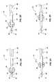
- FIG. 2Ais a top view of the implant of FIG. 1 as it passes through a cross section of a femoral tunnel;
- FIG. 2Bis a top view of the implant of FIG. 1 as it passes through a cross section of a femoral tunnel, the implant being shown in a position inserted further than the position shown in FIG. 2A ;
- FIG. 2Cis a top view of the implant of FIG. 1 as it passes through a cross section of a femoral tunnel, the implant being shown in a position inserted further than the position shown in FIG. 2B ;
- FIG. 2Dis a top view of the implant of FIG. 1 as it passes through a cross section of a femoral tunnel, the implant being shown in a position inserted further than the position shown in FIG. 2C ;
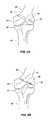
- FIG. 3Ais a diagrammatical view of a femur and a tibia to illustrate flexible strands bringing up soft tissue grafts into the femur;
- FIG. 3Bis a diagrammatical view of a femur and a tibia as in FIG. 3A showing the soft tissue grafts drawn further into the femur;
- FIG. 4Ais a diagrammatical view of a femur and a tibia as in FIG. 3A showing a passing pin driven through the femur to position the implant of FIG. 1 ;
- FIG. 4Bis a diagrammatical view of a femur and a tibia as in FIG. 4A showing the implant of FIG. 1 entering the transverse tunnel;
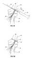
- FIG. 5Ais a diagrammatical view of a femur and a tibia to illustrate the implant of FIG. 1 being placed in a fully recessed position by an impactor with a projecting tip;
- FIG. 5Bis a diagrammatical view of a femur and a tibia to illustrate the implant of FIG. 1 placed in a fully recessed position;
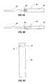
- FIGS. 6A and 6Bare two different configured drill tips which may be used in accordance with the methods of the present invention.
- FIG. 6Cis a side view of a cannulated drill guide
- FIG. 7Ais a diagrammatical view of a femur and a tibia to illustrate use of the cannulated drill guide during drilling of the femur;
- FIG. 7Bis a diagrammatical view of a femur and a tibia as shown in FIG. 7A showing the drill extending through the femur;
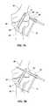
- FIG. 8Ais a diagrammatical view of a femur and a tibia to illustrate the principles of the present invention may be used in drilling from the medial to the lateral direction (inside of the knee to the outside), which is opposite to the directions as shown in the other figures; and
- FIG. 8Bis a diagrammatical view of a femur and a tibia as illustrated in FIG. 8A , showing the implant of the present invention embedded in the transverse tunnel.
- the method of the present inventionallows for the successful placement of a transversely placed implant into the femur to secure a flexible ligament graft used in the reconstruction of the anterior cruciate ligament.
- the novel implant and method of graft fixation of the present inventionprovides multiple advantages over the previous methods and implants described above.
- the current implantmay be of a solid form with a distal portion and a body portion attached to a multi-angular end portion.
- the distal portionmay include an eyelet for the placement of a suture or other flexible material used in directing the implant around the replacement ligament.
- the implantmay be secured into bone by impacting the multi-angular end, that has a slightly larger external dimension than the transverse round hole into the corresponding bone, and making it flush with external bone cortex.
- the compressive forces inherent to the geometrical mis-match between the implant and the transverse tunnelsecure the implant in place.
- the geometry of the present implantallows for a smaller profile and leads to the applicability of materials not heretofore utilized in transverse ligament fixation.
- the implant 12preferably includes a proximal end 14 , a distal end 16 and defines a longitudinal axis 18 .
- the implant 12may be constructed of any suitable material such as metal, polymer, or bone that is preferably inert or biologically compatible.
- the implant 12is preferably substantially solid, characterized by the absence of a cannulation along the longitudinal axis 18 .
- the implant 12may include a multi-angular portion 20 at the proximal end 14 .
- the multi-angular portion 20preferably has a polygonal cross section which may form a square for example. It will be appreciated that the multi-angular portion 20 may be formed of various different polygonal shapes, such as triangular, pentagonal, hexagonal, etc., within the scope of the present invention.
- the multi-angular portion 20preferably forms a plurality of ridges 22 which extend substantially parallel to the longitudinal axis 18 .
- the multi-angular portion 20is preferably configured to have a slightly larger cross section than a hole in the bone receiving the implant 12 such that an interference fit is formed between the bone and the ridges 22 to hold the implant 12 in place.
- An interference fit as used hereinrefers to an abutting contact between two objects to prevent the two objects from moving with respect to each other in a particular direction.
- the multi-angular portion 20may also include a fitting 32 on the proximal end 14 for receiving a driver 54 (see FIG. 5A ) to drive the implant 12 into the bone.
- the fitting 32may be formed as a recess that is configured to receive a projecting tip 56 of the driver 54 to maintain contact between the driver 54 and the implant 12 while the implant 12 is being driven into the bone.
- the multi-angular portion 20may be replaced with a threaded portion (not shown).
- the threaded portionmay have a cylindrical configuration with threads on the exterior surface to grip the receptor bone for fixing the implant 12 in place.
- the implant 12may also include a body portion 24 adjoining the multi-angular portion 20 .
- the body portion 24may have a cylindrical configuration which may have a slightly smaller radial dimension than the multi-angular portion 20 such that the ridges 22 extend radially beyond the body portion 24 , as is clearly shown in FIG. 1 B.
- the body portion 24is preferably configured to facilitate insertion of the implant 12 within a bone.
- the surface of the body portion 24is preferably substantially smooth, without threads or ridges for example.
- a radial dimension 21 of the body portion 24is substantially equal to a radial dimension of the multi-angular portion 20 at a point 23 between the ridges 22
- a radial dimension 25 of the multi-angular portion 20 at the ridges 22is larger than the radial dimension 21 of the body portion 24 .
- This relationship of sizeshelps the insertion of the implant 12 , since a smooth transition exists between the body portion 24 and the multi-angular portion 20 at the point 23 between the ridges 22 .
- the larger radial dimension 25 of the ridges 22provides an interference fit between the ridges 22 and the receptor bone when the implant 12 is installed. It will be appreciated however, that other radial dimensions may be used within the scope of the present invention.
- Adjoining the body portion 24is preferably a tapered portion 26 .
- the tapered portion 26preferably has a taper such that the cross sectional area of the tapered portion 26 reduces from the body portion 24 toward a distal portion 28 at the distal end 16 of the implant 12 .
- the amount of taper of the tapered portion 24is preferably sufficient to form a shoulder between the body portion 24 and the distal portion 28 to prevent the implant 12 from being inserted too far into the bone as discussed more fully below.
- the distal portion 28may have a substantially cylindrical shaped configuration, or may have a conical configuration with a tapered exterior surface to facilitate insertion of the implant 12 into the bone.
- An eyelet or opening 30is preferably formed in the distal portion 28 , in a direction transverse to the longitudinal axis 18 for receiving a flexible strand or suture.
- FIGS. 2A-2Dshow top views of the implant 12 as it progressively passes through a cross section of a femoral tunnel 34 (a description of the femoral tunnel is provided in greater detail below).
- the implant 12is inserted transverse to the femoral tunnel 34 to attach replacement ligaments or soft tissue grafts 36 within the femoral tunnel 34 .
- the replacement ligaments or soft tissue grafts 36may be formed of any variety of biologic and synthetic materials known to those skilled in the art of reconstructing damaged natural ligaments.
- the conical distal portion 28facilitates insertion of the implant 12 through the femoral tunnel 34 .
- the taper of the distal portion 28causes the soft tissue grafts 36 to be compressed against a sidewall of the femoral tunnel 34 .
- FIG. 2Cfurther compression of the soft tissue grafts 36 occurs as the tapered portion 26 and body portion 24 are inserted into the femoral tunnel 34 .
- the larger diameter of the body portioncompresses the soft tissue grafts 36 in place against a sidewall of the femoral tunnel 34 , and the tapered portion 26 forms a shoulder which abuts against an annular seat 46 in the receptor bone, as shown in FIGS. 3-5 , to prevent the implant 12 from being inserted too far into the receptor bone.
- the implant 12is preferably configured to have a rate of taper from the proximal end 14 to the distal end 16 .
- the rate of taperis defined as the change in radial distance from the center of the implant 12 to the exterior surface of the implant, per unit distance along the longitudinal axis 18 .
- the body portion 24preferably has a uniform cylindrical cross section and therefore has no taper, whereas the tapered portion 26 has a larger rate of taper than the body portion 24 or the distal portion 28 .
- the higher rate of taper of the tapered portion 26forms a shoulder that is positioned a predetermined distance from a proximal most end of the body portion 24 to thereby engage in contact against the annular seat 46 formed within the femur 38 and thereby limit an insertion depth of the implant 12 .
- the implant 12is preferably configured and dimensioned such that the distal portion 28 and body portion 24 are long enough to extend across the femoral tunnel 34 to facilitate insertion of the implant 12 and provide uniform support of the soft tissue grafts 36 .
- the tapered portion 26is configured to be relatively short in comparison with the distal portion 28 and the body portion 24 to form a shoulder between the distal portion 28 and the body portion 24 .
- the shoulder formed by the relatively short tapered portion 26allows for more control over the fully inserted position of the implant 12 .
- the length of the multi-angular portion 20is configured to provide adequate support to secure the implant 12 within the transverse tunnel 48 .
- FIGS. 3A-3Bshow diagrammatical views of a femur 38 and a tibia 40 with portions broken away to illustrate flexible strands 42 bringing up soft tissue grafts 36 into the femur 38 .
- Flexible strands 42may include any variety of surgical filaments known to those skilled in the art.
- a longitudinal tunnel 44is formed in the tibia 40 and femur 38 in a manner known to those skilled in the art. The longitudinal tunnel 44 extends into the femur to form the femoral tunnel 34 .
- a transverse tunnel 48is formed in the femur 38 , in a manner described more fully below.
- the transverse tunnel 48has a smaller diameter than the femoral tunnel 34 , and the transverse tunnel 48 penetrates the femoral tunnel 34 at an approximate right angle.
- flexible strands 42are preferably looped around soft tissue grafts 36 in preparation for ACL reconstruction of the knee.
- Two flexible strands 42 , and two soft tissue grafts 36are shown in FIG. 3A , however, it will be appreciated that other quantities of strands 42 and soft tissue grafts 36 may be used within the scope of the present invention.
- the flexible strands 42are preferably placed retrograde into the femoral tunnel 34 and grasped by an instrument 50 through the transverse tunnel 48 to then be brought outside of the femur 38 .
- Instrument 50may be any suitable tool known in the art, such as grasping forceps, or a snap on attachment to an arthroscope for example. As shown in FIG.
- the soft tissue grafts 36may be pulled into the femoral tunnel 34 and the flexible strands 42 may exit the femur 38 through the transverse tunnel 48 . It will be appreciated that the method described above may be used to position the soft tissue graft 36 in the longitudinal tunnel 44 for securing the soft tissue grafts 36 using staples, implants or any other manner known in the art, within the scope of the present invention.
- a pair of the flexible strands 42may be place through the eyelet 30 of the implant 12 and tied into a knot.
- the other pair of the flexible strands 42may be passed through an eye of a passing pin or “Beath” pin 52 .
- the passing pin 52may be driven through the transverse tunnel 48 and out the opposite side of the femur 38 .
- FIG. 4Bas the flexible strands 42 are pulled away from the implant 12 causing tensioning of the flexible strands 42 , the soft tissue grafts 36 may be brought further up into the femoral tunnel 34 , and the implant 12 may be pulled into the transverse tunnel 48 .
- the implant 12may be pulled underneath the soft tissue grafts 36 until the tapered portion 26 makes contact with the annular seat 46 in the femur 38 surrounding the transverse tunnel 48 .
- a driver or impactor 54 having a projecting tip 56may be used to seat the implant 12 within the transverse tunnel 48 .
- the projecting tip 56may be inserted into the fitting 32 , as shown most clearly in FIG. 1 , to maintain contact between the driver 54 and the implant 12 .
- the driver 54may be used to force the implant 12 into the transverse tunnel 48 until the implant 12 is fully inserted to the point where the tapered portion 26 contacts the annular seat 46 , and where the implant is in a recessed position within the femur 38 , as shown in FIG. 5 B.
- the driver 54may be any suitable tool known to those skilled in the art for forcing the implant 12 into the transverse tunnel 48 .
- FIGS. 6A , 6 B, and 6 Ca side view is shown of a cannulated drill guide 58 and two different embodiments of drill tips, generally indicated at 60 , which may be used to form the transverse tunnel 48 in accordance with the principles of the present invention.
- the drill guide 58includes an aperture 62 for receiving the drill tip 60 to allow the transverse tunnel 48 to be positioned properly with respect to the femoral tunnel 34 .
- the aperture 62preferably has a funnel shape to direct the drill tips 60 into the center of the passage 70 .
- the drill tips 60preferably include a small diameter portion 64 and a larger diameter portion 66 separated by an abutment portion 68 .
- the small diameter portion 64may be used to drill a portion of the transverse tunnel 48 for receiving the passing pin 52 , whereas the larger diameter portion 66 may be used for drilling a portion of the transverse tunnel 48 for receiving the implant 12 .
- the two different diameters of the drill tip 60allow for different sized portions of the transverse tunnel 48 to be drilled in a single step.
- the drill guide 58may be inserted into the longitudinal tunnel 44 and attached to an external drill arm and guide 72 .
- the two step drill 60may be placed in a guide barrel 74 to ensure that the transverse tunnel 48 is positioned properly.
- the funnel shaped aperture 62guides the drill 60 through the passage 70 until the abutment 68 contacts the drill guide 58 as shown in FIG. 7 B. At this point the drill 60 is prevented from extending further into the femur 38 and proper drilling of the transverse tunnel 48 is achieved.
- the principles of the present inventionmay be used in drilling from the medial side 76 of the femur 38 to the lateral side 78 of the femur 38 (inside of the knee to the outside), which is opposite to the directions as shown in the preceding figures. Therefore, the implant 12 may be installed on the opposite side of the knee as previously discussed.
- the smaller-dimensioned distal portion 28facilitates the crossing of the implant 12 across the lumen of the longitudinal tunnel 44 , directed with a suture “leash,” minimizing interaction of the implant 12 with the replacement ligament 36 until the distal portion 28 has reached the smaller diameter portion of the transverse tunnel 48 on the opposite side of the longitudinal tunnel 44 .
- the larger-dimensioned, cylindrical body portion 24serves to secure the replacement ligament 36 either by compressing it against the tunnel walls (in the case of a looped material), or by blocking the egress of the replacement ligament (in the case of an attached block of bone).
- the utility of such an implantcan be seen by being applicable for use in either the femur 38 or the tibia 40 and with replacement ligaments made out of soft tissue, bone block attached, or synthetic material.
- the method of insertion of this implantis not contemplated by previous methods due to the lack of cannulation in the present implant.
- the process of developing a transverse tunnel 48 which intersects the precise center of the longitudinal bone tunnel 44is made possible by the novel cannulated guide 58 and stepped drill 60 .
- the guide 58is first placed into the longitudinal bone tunnel 44 with the funnel shaped aperture 62 of the transverse cannulation or passage 70 directed towards the transverse drill guide 72 that is aimed at a perpendicular, directly to the center of the longitudinal tunnel 44 .
- a drill tip 60 with an initial smaller diameter portion 64 capable of passing through the transverse cannulation 70 of the guide 58 within the longitudinal tunnel 44 , and with sufficient length to broach the opposing cortex of bone combined with the larger diameter portion 66 forming the abutment 68 that stops the progress of the drill once reaching the longitudinal tunnel 44is used to construct a transverse tunnel 48 of two different bore dimensions with a single pass.
- the drill tip 60 and cannulated guide 58are then removed from the bone.
- the graft 36may then be brought into the longitudinal tunnel 44 by first looping the graft 36 with a flexible strand 42 and then passing the flexible strand 42 into the longitudinal tunnel 44 in a retrograde fashion.
- the flexible strand 42may then be brought out the medial and lateral aspects of the bone using the passing pin 52 .
- the flexible strand 42may be tensioned by pulling opposing portions of the strand 42 in substantially opposite directions wherein the graft 36 is brought up into the longitudinal tunnel 44 until it sits just above the flexible strand 42 which is now straight in line with the course of the previously constructed transverse tunnel 48 .
- One end of the flexible strand 42may then be attached to the implant 12 and with or without the use of an impaction instrument 54 , the implant 12 may be brought into and across the longitudinal bone tunnel 44 thus securing the replacement ligament 36 .
- the implant 12may be either driven flush with the external cortex or cut flush with an appropriate cutting device.
- This method and implantcan be utilized in either the femur 38 or the tibia 40 and with a variety of replacement ligament types unlike other systems which have been constrained to specific grafts.
- any structure, apparatus or system that perform functions the same as, or equivalent to, those disclosed hereinare intended to fall within the scope of a means for directing and securing a placement ligament into the femur or tibia of the knee, including those structures, apparatus or systems that are presently known, or which may become available in the future. Anything which functions the same as, or equivalently to, a means for directing and securing a placement ligament into the femur or tibia of the knee falls within the scope of this element.
- a preferred method for fixing a replacement ligament within a first tunnel of a boneincludes the steps of:
Landscapes
- Health & Medical Sciences (AREA)
- Life Sciences & Earth Sciences (AREA)
- Surgery (AREA)
- Orthopedic Medicine & Surgery (AREA)
- Public Health (AREA)
- Animal Behavior & Ethology (AREA)
- Oral & Maxillofacial Surgery (AREA)
- Veterinary Medicine (AREA)
- Engineering & Computer Science (AREA)
- Biomedical Technology (AREA)
- Heart & Thoracic Surgery (AREA)
- General Health & Medical Sciences (AREA)
- Molecular Biology (AREA)
- Nuclear Medicine, Radiotherapy & Molecular Imaging (AREA)
- Medical Informatics (AREA)
- Dentistry (AREA)
- Rheumatology (AREA)
- Rehabilitation Therapy (AREA)
- Cardiology (AREA)
- Transplantation (AREA)
- Vascular Medicine (AREA)
- Prostheses (AREA)
- Surgical Instruments (AREA)
Abstract
Description
Claims (27)
Priority Applications (3)
| Application Number | Priority Date | Filing Date | Title |
|---|---|---|---|
| US10/061,094US6878166B2 (en) | 2000-08-28 | 2002-02-01 | Method and implant for securing ligament replacement into the knee |
| US11/059,869US7837718B2 (en) | 2000-08-28 | 2005-02-16 | Method and implant for securing ligament replacement into the knee |
| US11/061,950US7530999B2 (en) | 2000-08-28 | 2005-02-17 | Method and implant for securing ligament replacement into the knee |
Applications Claiming Priority (3)
| Application Number | Priority Date | Filing Date | Title |
|---|---|---|---|
| US22835700P | 2000-08-28 | 2000-08-28 | |
| US94211101A | 2001-08-28 | 2001-08-28 | |
| US10/061,094US6878166B2 (en) | 2000-08-28 | 2002-02-01 | Method and implant for securing ligament replacement into the knee |
Related Parent Applications (1)
| Application Number | Title | Priority Date | Filing Date |
|---|---|---|---|
| US94211101AContinuation | 2000-08-28 | 2001-08-28 |
Related Child Applications (2)
| Application Number | Title | Priority Date | Filing Date |
|---|---|---|---|
| US11/059,869ContinuationUS7837718B2 (en) | 2000-08-28 | 2005-02-16 | Method and implant for securing ligament replacement into the knee |
| US11/061,950Continuation-In-PartUS7530999B2 (en) | 2000-08-28 | 2005-02-17 | Method and implant for securing ligament replacement into the knee |
Publications (2)
| Publication Number | Publication Date |
|---|---|
| US20020087160A1 US20020087160A1 (en) | 2002-07-04 |
| US6878166B2true US6878166B2 (en) | 2005-04-12 |
Family
ID=26922295
Family Applications (2)
| Application Number | Title | Priority Date | Filing Date |
|---|---|---|---|
| US10/061,094Expired - LifetimeUS6878166B2 (en) | 2000-08-28 | 2002-02-01 | Method and implant for securing ligament replacement into the knee |
| US11/059,869Expired - Fee RelatedUS7837718B2 (en) | 2000-08-28 | 2005-02-16 | Method and implant for securing ligament replacement into the knee |
Family Applications After (1)
| Application Number | Title | Priority Date | Filing Date |
|---|---|---|---|
| US11/059,869Expired - Fee RelatedUS7837718B2 (en) | 2000-08-28 | 2005-02-16 | Method and implant for securing ligament replacement into the knee |
Country Status (1)
| Country | Link |
|---|---|
| US (2) | US6878166B2 (en) |
Cited By (27)
| Publication number | Priority date | Publication date | Assignee | Title |
|---|---|---|---|---|
| US20040193167A1 (en)* | 2002-04-16 | 2004-09-30 | Arthrocare Corporation | Transverse suspension device |
| US20050149187A1 (en)* | 2000-08-28 | 2005-07-07 | Ron Clark | Method and implant for securing ligament replacement into the knee |
| US20050197662A1 (en)* | 2000-08-28 | 2005-09-08 | Ron Clark | Method and implant for securing ligament replacement into the knee |
| US20060095130A1 (en)* | 2004-10-29 | 2006-05-04 | Arthrex, Inc. | Ligament fixation using graft harness |
| US20060111719A1 (en)* | 2004-11-03 | 2006-05-25 | Strobel Michael J | Oval pin for fixing an implant subjected to tensile load |
| US20060235516A1 (en)* | 2005-04-01 | 2006-10-19 | Arthrocare Corporation | Surgical methods for anchoring and implanting tissues |
| US20060241694A1 (en)* | 2005-04-20 | 2006-10-26 | Daniel Cerundolo | Suture fixation device and method for surgical repair |
| US20060247641A1 (en)* | 2004-11-15 | 2006-11-02 | Paul Re | Method and apparatus for the repair of a rotator cuff (RTC) tendon or ligament |
| US20060271059A1 (en)* | 2005-05-16 | 2006-11-30 | Arthrocare Corporation | Convergent tunnel guide apparatus and method |
| US20080177336A1 (en)* | 2006-10-17 | 2008-07-24 | Arthroscopic Innovations Llc | Fixation device for surgical repair |
| US20080228271A1 (en)* | 2007-03-13 | 2008-09-18 | Biomet Sports Medicine, Inc. | Method and apparatus for graft fixation |
| US20090234396A1 (en)* | 2008-02-29 | 2009-09-17 | Lars G. Tellman | Method and apparatus for articular scapholunate reconstruction |
| US7686838B2 (en) | 2006-11-09 | 2010-03-30 | Arthrocare Corporation | External bullet anchor apparatus and method for use in surgical repair of ligament or tendon |
| US20100121448A1 (en)* | 2001-03-13 | 2010-05-13 | Depuy Mitek, Inc. | Method and apparatus for fixing a graft in a bone tunnel |
| US7896917B2 (en) | 2003-10-15 | 2011-03-01 | Biomet Sports Medicine, Llc | Method and apparatus for graft fixation |
| US7901404B2 (en) | 2004-01-16 | 2011-03-08 | Arthrocare Corporation | Bone harvesting device and method |
| US20110118838A1 (en)* | 2009-11-16 | 2011-05-19 | George Delli-Santi | Graft pulley and methods of use |
| US20110118837A1 (en)* | 2009-11-16 | 2011-05-19 | George Delli-Santi | Graft pulley and methods of use |
| US20110137416A1 (en)* | 2009-03-31 | 2011-06-09 | Thomas H. Myers | Double bundle acl repair |
| US8002778B1 (en)* | 2004-06-28 | 2011-08-23 | Biomet Sports Medicine, Llc | Crosspin and method for inserting the same during soft ligament repair |
| US20120059469A1 (en)* | 2009-03-31 | 2012-03-08 | Medicinelodge, Inc. Dba Imds Co-Innovation | Double bundle acl repair system |
| US8968402B2 (en) | 2011-10-18 | 2015-03-03 | Arthrocare Corporation | ACL implants, instruments, and methods |
| US9962174B2 (en) | 2015-07-17 | 2018-05-08 | Kator, Llc | Transosseous method |
| US10143462B2 (en) | 2015-08-04 | 2018-12-04 | Kator, Llc | Transosseous suture anchor method |
| US10154868B2 (en) | 2015-07-17 | 2018-12-18 | Kator, Llc | Transosseous method |
| US11504140B2 (en) | 2015-07-17 | 2022-11-22 | Crossroads Extremity Systems, Llc | Transosseous guide and method |
| US12383253B2 (en) | 2015-08-04 | 2025-08-12 | Crossroads Extremity Systems, Llc | Suture anchor |
Families Citing this family (89)
| Publication number | Priority date | Publication date | Assignee | Title |
|---|---|---|---|---|
| US7077863B2 (en)* | 1997-02-12 | 2006-07-18 | Arthrex, Inc. | Transverse fixation technique for ACL reconstruction using bone-tendon-bone graft with loop at end |
| US6623524B2 (en)* | 2000-06-09 | 2003-09-23 | Arthrex, Inc. | Method for anterior cruciate ligament reconstruction using cross-pin implant with eyelet |
| US8512376B2 (en) | 2002-08-30 | 2013-08-20 | Arthrex, Inc. | Method and apparatus for internal fixation of an acromioclavicular joint dislocation of the shoulder |
| US7033364B1 (en)* | 2002-01-31 | 2006-04-25 | Arthrotek, Inc. | Apparatus and method for manipulating a flexible strand and soft tissue replacement during surgery |
| US7713300B2 (en)* | 2002-01-31 | 2010-05-11 | Biomet Sports Medicince, LLC | Apparatus and method for manipulating a flexible strand and soft tissue replacement during surgery |
| US20060206206A1 (en) | 2003-06-06 | 2006-09-14 | Peyman Gholam A | Intraocular telescope |
| US7270666B2 (en)* | 2002-05-15 | 2007-09-18 | Linvatec Corporation | Cross-pin graft fixation, instruments, and methods |
| US7338492B2 (en)* | 2002-05-15 | 2008-03-04 | Linvatec Corporation | Cross-pin graft fixation, instruments, and methods |
| US7300439B2 (en)* | 2003-06-24 | 2007-11-27 | Depuy Mitek, Inc. | Porous resorbable graft fixation pin |
| US7341592B1 (en) | 2003-10-15 | 2008-03-11 | Biomet Sports Medicine, Inc. | Method and apparatus for graft fixation |
| US8088128B2 (en) | 2004-03-25 | 2012-01-03 | Depuy Mitek, Inc. | Implantable cross-pin for anterior cruciate ligament repair |
| DE102004048042B4 (en)* | 2004-09-29 | 2011-12-01 | Karl Storz Gmbh & Co.Kg | Device for guiding a drilling tool |
| US8303604B2 (en) | 2004-11-05 | 2012-11-06 | Biomet Sports Medicine, Llc | Soft tissue repair device and method |
| US8137382B2 (en) | 2004-11-05 | 2012-03-20 | Biomet Sports Medicine, Llc | Method and apparatus for coupling anatomical features |
| US8361113B2 (en) | 2006-02-03 | 2013-01-29 | Biomet Sports Medicine, Llc | Method and apparatus for coupling soft tissue to a bone |
| US8128658B2 (en) | 2004-11-05 | 2012-03-06 | Biomet Sports Medicine, Llc | Method and apparatus for coupling soft tissue to bone |
| US8840645B2 (en) | 2004-11-05 | 2014-09-23 | Biomet Sports Medicine, Llc | Method and apparatus for coupling soft tissue to a bone |
| US9017381B2 (en) | 2007-04-10 | 2015-04-28 | Biomet Sports Medicine, Llc | Adjustable knotless loops |
| US7909851B2 (en) | 2006-02-03 | 2011-03-22 | Biomet Sports Medicine, Llc | Soft tissue repair device and associated methods |
| US7658751B2 (en) | 2006-09-29 | 2010-02-09 | Biomet Sports Medicine, Llc | Method for implanting soft tissue |
| US9801708B2 (en) | 2004-11-05 | 2017-10-31 | Biomet Sports Medicine, Llc | Method and apparatus for coupling soft tissue to a bone |
| US7857830B2 (en) | 2006-02-03 | 2010-12-28 | Biomet Sports Medicine, Llc | Soft tissue repair and conduit device |
| US8118836B2 (en) | 2004-11-05 | 2012-02-21 | Biomet Sports Medicine, Llc | Method and apparatus for coupling soft tissue to a bone |
| US8298262B2 (en) | 2006-02-03 | 2012-10-30 | Biomet Sports Medicine, Llc | Method for tissue fixation |
| US8088130B2 (en) | 2006-02-03 | 2012-01-03 | Biomet Sports Medicine, Llc | Method and apparatus for coupling soft tissue to a bone |
| US7905904B2 (en) | 2006-02-03 | 2011-03-15 | Biomet Sports Medicine, Llc | Soft tissue repair device and associated methods |
| US7749250B2 (en) | 2006-02-03 | 2010-07-06 | Biomet Sports Medicine, Llc | Soft tissue repair assembly and associated method |
| US8998949B2 (en) | 2004-11-09 | 2015-04-07 | Biomet Sports Medicine, Llc | Soft tissue conduit device |
| US8652172B2 (en) | 2006-02-03 | 2014-02-18 | Biomet Sports Medicine, Llc | Flexible anchors for tissue fixation |
| US9078644B2 (en) | 2006-09-29 | 2015-07-14 | Biomet Sports Medicine, Llc | Fracture fixation device |
| US8562647B2 (en) | 2006-09-29 | 2013-10-22 | Biomet Sports Medicine, Llc | Method and apparatus for securing soft tissue to bone |
| US8771352B2 (en) | 2011-05-17 | 2014-07-08 | Biomet Sports Medicine, Llc | Method and apparatus for tibial fixation of an ACL graft |
| US11311287B2 (en) | 2006-02-03 | 2022-04-26 | Biomet Sports Medicine, Llc | Method for tissue fixation |
| US9538998B2 (en) | 2006-02-03 | 2017-01-10 | Biomet Sports Medicine, Llc | Method and apparatus for fracture fixation |
| US8597327B2 (en) | 2006-02-03 | 2013-12-03 | Biomet Manufacturing, Llc | Method and apparatus for sternal closure |
| US8968364B2 (en) | 2006-02-03 | 2015-03-03 | Biomet Sports Medicine, Llc | Method and apparatus for fixation of an ACL graft |
| US8506597B2 (en) | 2011-10-25 | 2013-08-13 | Biomet Sports Medicine, Llc | Method and apparatus for interosseous membrane reconstruction |
| US8574235B2 (en) | 2006-02-03 | 2013-11-05 | Biomet Sports Medicine, Llc | Method for trochanteric reattachment |
| US8652171B2 (en) | 2006-02-03 | 2014-02-18 | Biomet Sports Medicine, Llc | Method and apparatus for soft tissue fixation |
| US11259792B2 (en) | 2006-02-03 | 2022-03-01 | Biomet Sports Medicine, Llc | Method and apparatus for coupling anatomical features |
| US9149267B2 (en) | 2006-02-03 | 2015-10-06 | Biomet Sports Medicine, Llc | Method and apparatus for coupling soft tissue to a bone |
| US9468433B2 (en) | 2006-02-03 | 2016-10-18 | Biomet Sports Medicine, Llc | Method and apparatus for forming a self-locking adjustable loop |
| US8562645B2 (en) | 2006-09-29 | 2013-10-22 | Biomet Sports Medicine, Llc | Method and apparatus for forming a self-locking adjustable loop |
| US8251998B2 (en) | 2006-08-16 | 2012-08-28 | Biomet Sports Medicine, Llc | Chondral defect repair |
| US9271713B2 (en) | 2006-02-03 | 2016-03-01 | Biomet Sports Medicine, Llc | Method and apparatus for tensioning a suture |
| US10517587B2 (en) | 2006-02-03 | 2019-12-31 | Biomet Sports Medicine, Llc | Method and apparatus for forming a self-locking adjustable loop |
| US8801783B2 (en) | 2006-09-29 | 2014-08-12 | Biomet Sports Medicine, Llc | Prosthetic ligament system for knee joint |
| US9918826B2 (en) | 2006-09-29 | 2018-03-20 | Biomet Sports Medicine, Llc | Scaffold for spring ligament repair |
| US8672969B2 (en) | 2006-09-29 | 2014-03-18 | Biomet Sports Medicine, Llc | Fracture fixation device |
| US11259794B2 (en) | 2006-09-29 | 2022-03-01 | Biomet Sports Medicine, Llc | Method for implanting soft tissue |
| US8500818B2 (en) | 2006-09-29 | 2013-08-06 | Biomet Manufacturing, Llc | Knee prosthesis assembly with ligament link |
| US12419632B2 (en) | 2008-08-22 | 2025-09-23 | Biomet Sports Medicine, Llc | Method and apparatus for coupling anatomical features |
| US12245759B2 (en) | 2008-08-22 | 2025-03-11 | Biomet Sports Medicine, Llc | Method and apparatus for coupling soft tissue to bone |
| US20100121375A1 (en)* | 2008-11-13 | 2010-05-13 | Pandya Rajiv D | Suture anchoring system and method |
| US8439976B2 (en)* | 2009-03-31 | 2013-05-14 | Arthrex, Inc. | Integrated adjustable button-suture-graft construct with two fixation devices |
| US8460379B2 (en) | 2009-03-31 | 2013-06-11 | Arthrex, Inc. | Adjustable suture button construct and methods of tissue reconstruction |
| US8343227B2 (en) | 2009-05-28 | 2013-01-01 | Biomet Manufacturing Corp. | Knee prosthesis assembly with ligament link |
| US12096928B2 (en) | 2009-05-29 | 2024-09-24 | Biomet Sports Medicine, Llc | Method and apparatus for coupling soft tissue to a bone |
| EP2455001B1 (en) | 2010-11-17 | 2020-07-22 | Arthrex, Inc. | Adjustable suture-button constructs for ligament reconstruction |
| EP2455002B1 (en) | 2010-11-17 | 2019-04-03 | Arthrex, Inc. | Adjustable suture-button construct for ankle syndesmosis repair |
| EP2455040B1 (en) | 2010-11-17 | 2015-03-04 | Arthrex, Inc. | Adjustable suture-button construct for knotless stabilization of cranial cruciate deficient ligament stifle |
| US12329373B2 (en) | 2011-05-02 | 2025-06-17 | Biomet Sports Medicine, Llc | Method and apparatus for soft tissue fixation |
| US9301745B2 (en) | 2011-07-21 | 2016-04-05 | Arthrex, Inc. | Knotless suture constructs |
| US9332979B2 (en) | 2011-07-22 | 2016-05-10 | Arthrex, Inc. | Tensionable knotless acromioclavicular repairs and constructs |
| US9107653B2 (en) | 2011-09-22 | 2015-08-18 | Arthrex, Inc. | Tensionable knotless anchors with splice and methods of tissue repair |
| US10245016B2 (en) | 2011-10-12 | 2019-04-02 | Arthrex, Inc. | Adjustable self-locking loop constructs for tissue repairs and reconstructions |
| US9357991B2 (en) | 2011-11-03 | 2016-06-07 | Biomet Sports Medicine, Llc | Method and apparatus for stitching tendons |
| US9314241B2 (en) | 2011-11-10 | 2016-04-19 | Biomet Sports Medicine, Llc | Apparatus for coupling soft tissue to a bone |
| US9370350B2 (en) | 2011-11-10 | 2016-06-21 | Biomet Sports Medicine, Llc | Apparatus for coupling soft tissue to a bone |
| US9381013B2 (en) | 2011-11-10 | 2016-07-05 | Biomet Sports Medicine, Llc | Method for coupling soft tissue to a bone |
| EP2601894B1 (en) | 2011-12-09 | 2018-08-29 | Arthrex, Inc. | Tensionable knotless anchor systems |
| US9737292B2 (en) | 2012-06-22 | 2017-08-22 | Arthrex, Inc. | Knotless suture anchors and methods of tissue repair |
| US9381096B2 (en) | 2012-09-13 | 2016-07-05 | Biomet Manufacturing, Llc | Method and apparatus to identify coordinated components |
| US9757119B2 (en) | 2013-03-08 | 2017-09-12 | Biomet Sports Medicine, Llc | Visual aid for identifying suture limbs arthroscopically |
| US9918827B2 (en) | 2013-03-14 | 2018-03-20 | Biomet Sports Medicine, Llc | Scaffold for spring ligament repair |
| US10136886B2 (en) | 2013-12-20 | 2018-11-27 | Biomet Sports Medicine, Llc | Knotless soft tissue devices and techniques |
| US9615822B2 (en) | 2014-05-30 | 2017-04-11 | Biomet Sports Medicine, Llc | Insertion tools and method for soft anchor |
| US9700291B2 (en) | 2014-06-03 | 2017-07-11 | Biomet Sports Medicine, Llc | Capsule retractor |
| CN104000641B (en)* | 2014-06-13 | 2016-08-17 | 赵金忠 | A kind of shoulder joint bone grafting device under the conditions of Wicresoft |
| US10039543B2 (en) | 2014-08-22 | 2018-08-07 | Biomet Sports Medicine, Llc | Non-sliding soft anchor |
| US9955980B2 (en) | 2015-02-24 | 2018-05-01 | Biomet Sports Medicine, Llc | Anatomic soft tissue repair |
| US9974534B2 (en) | 2015-03-31 | 2018-05-22 | Biomet Sports Medicine, Llc | Suture anchor with soft anchor of electrospun fibers |
| US10265060B2 (en) | 2015-08-20 | 2019-04-23 | Arthrex, Inc. | Tensionable constructs with multi-limb locking mechanism through single splice and methods of tissue repair |
| US10335136B2 (en) | 2015-08-20 | 2019-07-02 | Arthrex, Inc. | Tensionable constructs with multi-limb locking mechanism through single splice and methods of tissue repair |
| US10064632B2 (en) | 2016-02-19 | 2018-09-04 | Rajiv D. Pandya | System and technique for accessing extra articular lesions or abnormalities or intra osseous lesions or bone marrow lesions |
| US9925010B2 (en) | 2016-02-19 | 2018-03-27 | Rajiv D. Pandya | System and technique for accessing extra articular lesions or abnormalities or intra osseous lesions or bone marrow lesions |
| US11419684B2 (en) | 2016-02-19 | 2022-08-23 | Rajiv D. Pandya | System and technique for accessing extra articular lesions or abnormalities or intra osseous lesions or bone marrow lesions |
| US11376079B2 (en) | 2016-02-19 | 2022-07-05 | Rajiv D. Pandya | System and technique for accessing extra articular lesions or abnormalities or intra osseous lesions or bone marrow lesions |
| US11963688B2 (en) | 2021-11-20 | 2024-04-23 | Panorthopaedics, Inc. | Device adapted for lateral engagement of an elongated member |
Citations (24)
| Publication number | Priority date | Publication date | Assignee | Title |
|---|---|---|---|---|
| US461621A (en)* | 1891-10-20 | Island | ||
| US4338054A (en)* | 1979-11-19 | 1982-07-06 | Dahl Norman C | Solid externally threaded fasteners having greatly increased ductility |
| US4756307A (en)* | 1987-02-09 | 1988-07-12 | Zimmer, Inc. | Nail device |
| US4950270A (en) | 1989-02-03 | 1990-08-21 | Boehringer Mannheim Corporation | Cannulated self-tapping bone screw |
| US4985032A (en) | 1990-05-14 | 1991-01-15 | Marlowe Goble E | Drill guide |
| US5026374A (en)* | 1989-05-12 | 1991-06-25 | Orthofix S.R.L. | Bolt for orthopaedic surgical use |
| US5098435A (en) | 1990-11-21 | 1992-03-24 | Alphatec Manufacturing Inc. | Cannula |
| US5100405A (en)* | 1990-09-07 | 1992-03-31 | Mclaren Alexander C | Locking cap for medical implants |
| US5139520A (en) | 1990-01-31 | 1992-08-18 | American Cyanamid Company | Method for acl reconstruction |
| US5266075A (en) | 1992-10-05 | 1993-11-30 | Roy Clark | Tendon threader for endosteal ligament mounting |
| US5300077A (en) | 1990-07-16 | 1994-04-05 | Arthrotek | Method and instruments for ACL reconstruction |
| US5350380A (en) | 1993-01-15 | 1994-09-27 | Depuy Inc. | Method for securing a ligament replacement in a bone |
| US5354300A (en) | 1993-01-15 | 1994-10-11 | Depuy Inc. | Drill guide apparatus for installing a transverse pin |
| US5356413A (en) | 1993-03-12 | 1994-10-18 | Mitek Surgical Products, Inc. | Surgical anchor and method for deploying the same |
| US5397356A (en) | 1993-01-15 | 1995-03-14 | Depuy Inc. | Pin for securing a replacement ligament to a bone |
| US5423823A (en) | 1993-02-18 | 1995-06-13 | Arthrex Inc. | Coring reamer |
| US5431651A (en) | 1993-02-08 | 1995-07-11 | Goble; E. Marlowe | Cross pin and set screw femoral and tibial fixation method |
| US5593408A (en)* | 1994-11-30 | 1997-01-14 | Sofamor S.N.C | Vertebral instrumentation rod |
| US5601562A (en) | 1995-02-14 | 1997-02-11 | Arthrex, Inc. | Forked insertion tool and metnod of arthroscopic surgery using the same |
| US5918604A (en) | 1997-02-12 | 1999-07-06 | Arthrex, Inc. | Method of loading tendons into the knee |
| US6267766B1 (en)* | 1999-05-28 | 2001-07-31 | Stephen S. Burkhart | Suture anchor reel device kit and method |
| US6306138B1 (en) | 1997-09-24 | 2001-10-23 | Ethicon, Inc. | ACL fixation pin and method |
| US20010053934A1 (en) | 2000-06-09 | 2001-12-20 | Arthrex, Inc. | Method of ACL reconstruction using allograft bone cross pin implant |
| US6752830B1 (en)* | 1999-07-20 | 2004-06-22 | Ethicon, Inc. | Apparatus and method for reconstructing a ligament |
Family Cites Families (114)
| Publication number | Priority date | Publication date | Assignee | Title |
|---|---|---|---|---|
| US2695607A (en) | 1951-04-24 | 1954-11-30 | Herbert E Hipps | Self-retaining bone retractor |
| US3871379A (en)* | 1971-08-26 | 1975-03-18 | Henry C N Clarke | Laparoscopy instruments and method for suturing and ligation |
| FR2165159A5 (en)* | 1971-12-21 | 1973-08-03 | Talan Maryan | |
| JPS529980Y2 (en)* | 1974-08-28 | 1977-03-03 | ||
| US4053982A (en) | 1976-03-23 | 1977-10-18 | Bernard Weissman | Dental anchor |
| USD249705S (en)* | 1977-05-20 | 1978-09-26 | London James T | Device for use in implanting a prosthesis in the humerus |
| US4257411A (en)* | 1979-02-08 | 1981-03-24 | Cho Kenneth O | Cruciate ligament surgical drill guide |
| US4386179A (en)* | 1980-05-07 | 1983-05-31 | Medical Research Associates, Ltd. | Hydrocarbon block copolymer with dispersed polysiloxane |
| US4535768A (en)* | 1981-08-26 | 1985-08-20 | South African Inventions Development Corporation | Set of surgical instruments |
| US4537185A (en)* | 1983-06-10 | 1985-08-27 | Denis P. Stednitz | Cannulated fixation screw |
| US4731084A (en)* | 1986-03-14 | 1988-03-15 | Richards Medical Company | Prosthetic ligament |
| US4922897A (en)* | 1986-10-03 | 1990-05-08 | Temple University | Apparatus and method for reconstructive surgery |
| US4795473A (en)* | 1987-01-09 | 1989-01-03 | Grimes James B | Extramedullary femoral head-neck prosthesis and method of implanting same |
| CH681957A5 (en)* | 1988-11-17 | 1993-06-30 | Synthes Ag | |
| US5004474A (en)* | 1989-11-28 | 1991-04-02 | Baxter International Inc. | Prosthetic anterior cruciate ligament design |
| EP0437174B1 (en)* | 1990-01-08 | 1993-12-22 | SULZER Medizinaltechnik AG | Artificial ligament and/or tendon replacement implant |
| US5030219A (en)* | 1990-01-22 | 1991-07-09 | Boehringer Mannheim Corporation | Glenoid component installation tools |
| US5454365A (en) | 1990-11-05 | 1995-10-03 | Bonutti; Peter M. | Mechanically expandable arthroscopic retractors |
| US5129902A (en)* | 1990-04-20 | 1992-07-14 | Marlowe Goble E | Endosteal ligament retainer and process |
| US5108396A (en)* | 1990-06-07 | 1992-04-28 | Smith & Nephew Richards Inc. | Intramedullary referenced humeral head resection guide |
| US5041129A (en)* | 1990-07-02 | 1991-08-20 | Acufex Microsurgical, Inc. | Slotted suture anchor and method of anchoring a suture |
| US5258016A (en) | 1990-07-13 | 1993-11-02 | American Cyanamid Company | Suture anchor and driver assembly |
| US5100417A (en)* | 1990-07-13 | 1992-03-31 | American Cyanamid Company | Suture anchor and driver assembly |
| US5257996A (en) | 1991-12-13 | 1993-11-02 | Mcguire David A | Surgical pin passer |
| US5480403A (en)* | 1991-03-22 | 1996-01-02 | United States Surgical Corporation | Suture anchoring device and method |
| US5112336A (en)* | 1991-05-14 | 1992-05-12 | Intermedics Orthopedics, Inc. | Drill guide and template for prosthetic devices |
| US5201744A (en)* | 1991-12-05 | 1993-04-13 | Jones Mark W | Method and device for suturing using a rod with a needle holder |
| US5234444A (en)* | 1991-12-06 | 1993-08-10 | Cyprus Endosurgical Tools, Inc. | Christoudias knot--transfer method and instrument |
| FR2684543B1 (en) | 1991-12-06 | 1999-04-09 | Max Perrin | ARTIFICIAL LIGAMENT, ESPECIALLY FOR THE ANKLE. |
| GB9202248D0 (en)* | 1992-02-03 | 1992-03-18 | Howmedica | Prosthesis for attachement without bone cement and method of attaching |
| US5425733A (en)* | 1992-02-19 | 1995-06-20 | Arthrex, Inc. | Interference screw with rounded back end and cannulated sheath for endosteal fixation of ligaments |
| CA2099228C (en)* | 1992-06-26 | 1996-05-21 | Emanuel Sam Fardell | Fastening nail |
| US5234434A (en)* | 1992-08-17 | 1993-08-10 | Marlowe Goble E | Mutliple guide sleeve drill guide |
| GB9221257D0 (en)* | 1992-10-09 | 1992-11-25 | Minnesota Mining & Mfg | Glenoid alignment guide |
| US5507812A (en)* | 1992-12-28 | 1996-04-16 | Moore; David E. | Modular prosthetic ligament |
| US5540703A (en)* | 1993-01-06 | 1996-07-30 | Smith & Nephew Richards Inc. | Knotted cable attachment apparatus formed of braided polymeric fibers |
| US5456722A (en) | 1993-01-06 | 1995-10-10 | Smith & Nephew Richards Inc. | Load bearing polymeric cable |
| US5868789A (en)* | 1997-02-03 | 1999-02-09 | Huebner; Randall J. | Removable suture anchor apparatus |
| US5632748A (en)* | 1993-06-14 | 1997-05-27 | Linvatec Corporation | Endosteal anchoring device for urging a ligament against a bone surface |
| US5370662A (en) | 1993-06-23 | 1994-12-06 | Kevin R. Stone | Suture anchor assembly |
| US6383199B2 (en)* | 1993-08-25 | 2002-05-07 | Inlet Medical, Inc. | Devices for investing within ligaments for retracting and reinforcing the same |
| EP0642773B1 (en)* | 1993-09-14 | 2003-05-28 | Lanny L. Johnson | Biological replacement ligament |
| US5545180A (en)* | 1993-12-13 | 1996-08-13 | Ethicon, Inc. | Umbrella-shaped suture anchor device with actuating ring member |
| US5618314A (en)* | 1993-12-13 | 1997-04-08 | Harwin; Steven F. | Suture anchor device |
| USD357534S (en)* | 1993-12-15 | 1995-04-18 | Zimmer, Inc. | Surgical parallel drill guide instrument |
| US5674224A (en) | 1994-11-18 | 1997-10-07 | Howell; Stephen M. | Bone mulch screw assembly for endosteal fixation of soft tissue grafts and method for using same |
| SE508120C2 (en)* | 1995-01-27 | 1998-08-31 | Robert J Medoff | Implantable device comprising a pin plate and pins |
| US5643273A (en)* | 1995-02-17 | 1997-07-01 | Clark; Ron | ACL bone tunnel projection drill guide and method for its use |
| US5643320A (en)* | 1995-03-13 | 1997-07-01 | Depuy Inc. | Soft tissue anchor and method |
| DK0831884T3 (en)* | 1995-06-05 | 2003-11-03 | Inst Genetics Llc | Use of bone morphogenetic proteins for healing and repair of connective tissue binding |
| US6231608B1 (en)* | 1995-06-07 | 2001-05-15 | Crosscart, Inc. | Aldehyde and glycosidase-treated soft and bone tissue xenografts |
| FR2749753B1 (en)* | 1996-06-14 | 1998-12-24 | Mosseri Raphael | TOTAL HIP PROSTHESIS FOR ENDO-ARTICULAR PLACEMENT AND ITS ANCILLARY DEVICE |
| US6984241B2 (en)* | 1996-09-13 | 2006-01-10 | Tendon Technology, Ltd. | Apparatus and methods for tendon or ligament repair |
| US5941885A (en)* | 1996-10-08 | 1999-08-24 | Jackson; Roger P. | Tools for use in installing osteosynthesis apparatus utilizing set screw with break-off head |
| US5891150A (en)* | 1996-12-04 | 1999-04-06 | Chan; Kwan-Ho | Apparatus and method for fixing a ligament in a bone tunnel |
| US6113604A (en)* | 1997-01-14 | 2000-09-05 | Ethicon, Inc. | Method and apparatus for fixing a graft in a bone tunnel |
| US5849013A (en) | 1997-01-14 | 1998-12-15 | Whittaker; Gregory R. | Method and apparatus for fixing a bone block in a bone tunnel |
| NL1005234C2 (en)* | 1997-02-10 | 1998-08-11 | Novarticulate Bv | Hip replacement and a method of placing such a hip replacement. |
| US6280472B1 (en)* | 1997-07-23 | 2001-08-28 | Arthrotek, Inc. | Apparatus and method for tibial fixation of soft tissue |
| EP0896825B1 (en)* | 1997-08-14 | 2002-07-17 | Sulzer Innotec Ag | Composition and device for in vivo cartilage repair comprising nanocapsules with osteoinductive and/or chondroinductive factors |
| US6511958B1 (en)* | 1997-08-14 | 2003-01-28 | Sulzer Biologics, Inc. | Compositions for regeneration and repair of cartilage lesions |
| US6379386B1 (en)* | 1997-09-09 | 2002-04-30 | Stryker Technologies Corporation | Anatomic glenoid shoulder prosthesis together with methods and tools for implanting same |
| US5980558A (en) | 1997-09-30 | 1999-11-09 | Biomet Inc. | Suture anchor system |
| US6066173A (en)* | 1998-01-28 | 2000-05-23 | Ethicon, Inc. | Method and apparatus for fixing a graft in a bone tunnel |
| US6146406A (en) | 1998-02-12 | 2000-11-14 | Smith & Nephew, Inc. | Bone anchor |
| US5984966A (en) | 1998-03-02 | 1999-11-16 | Bionx Implants Oy | Bioabsorbable bone block fixation implant |
| US6494913B1 (en) | 1998-03-17 | 2002-12-17 | Acumed, Inc. | Shoulder prosthesis |
| US5964764A (en) | 1998-03-24 | 1999-10-12 | Hugh S. West, Jr. | Apparatus and methods for mounting a ligament graft to a bone |
| DE29806564U1 (en)* | 1998-04-09 | 1999-08-12 | Howmedica Gmbh | Aiming device for a locking nail |
| US5997582A (en)* | 1998-05-01 | 1999-12-07 | Weiss; James M. | Hip replacement methods and apparatus |
| AU4193599A (en)* | 1998-05-21 | 1999-12-06 | Kwan-Ho Chan | Apparatus and method for ligament fixation |
| US6497726B1 (en) | 2000-01-11 | 2002-12-24 | Regeneration Technologies, Inc. | Materials and methods for improved bone tendon bone transplantation |
| US6436099B1 (en)* | 1999-04-23 | 2002-08-20 | Sdgi Holdings, Inc. | Adjustable spinal tether |
| US6499486B1 (en) | 1999-07-29 | 2002-12-31 | Ethicon, Inc. | Method for reconstructing a ligament |
| DE60032152T2 (en)* | 1999-08-10 | 2007-09-27 | Ethicon, Inc. | DEVICE FOR RESTORING A LIGAMENT |
| US6440373B1 (en)* | 1999-10-15 | 2002-08-27 | Bel-Art Products, Inc. | Device for collecting and storing samples |
| US20030097179A1 (en)* | 2000-01-11 | 2003-05-22 | Carter Kevin C. | Materials and methods for improved bone tendon bone transplantation |
| US6342056B1 (en)* | 2000-02-04 | 2002-01-29 | Jean-Marc Mac-Thiong | Surgical drill guide and method for using the same |
| AU2001251700A1 (en) | 2000-02-23 | 2001-09-03 | Ethicon Inc. | Apparatus and method for reconstructing a ligament |
| US6626945B2 (en) | 2000-03-14 | 2003-09-30 | Chondrosite, Llc | Cartilage repair plug |
| AU2001247476A1 (en) | 2000-03-16 | 2001-09-24 | Eugene M. Wolf M.D. Inc | Facile total shoulder arthroplasty apparatus and method |
| WO2001095835A1 (en)* | 2000-06-14 | 2001-12-20 | Jaervinen Teppo | Fixation anchor |
| US6325804B1 (en)* | 2000-06-28 | 2001-12-04 | Ethicon, Inc. | Method for fixing a graft in a bone tunnel |
| US6562044B1 (en)* | 2000-08-21 | 2003-05-13 | Daniel E. Cooper | Soft tissue fixation device |
| US7530999B2 (en) | 2000-08-28 | 2009-05-12 | Biomet Sports Medicine, Llc | Method and implant for securing ligament replacement into the knee |
| US6878166B2 (en)* | 2000-08-28 | 2005-04-12 | Ron Clark | Method and implant for securing ligament replacement into the knee |
| US6517579B1 (en)* | 2000-09-06 | 2003-02-11 | Lonnie E. Paulos | Method and apparatus for securing a soft tissue graft to bone during an ACL reconstruction |
| US6454768B1 (en)* | 2000-12-05 | 2002-09-24 | Roger P. Jackson | Removable gripping set screw |
| US6589281B2 (en)* | 2001-01-16 | 2003-07-08 | Edward R. Hyde, Jr. | Transosseous core approach and instrumentation for joint replacement and repair |
| US6780190B2 (en)* | 2001-01-23 | 2004-08-24 | Depuy Orthopaedics, Inc. | Method and apparatus for resecting a greater tubercle from a humerus of a patient during performance of a shoulder replacement procedure |
| US6517546B2 (en)* | 2001-03-13 | 2003-02-11 | Gregory R. Whittaker | Method and apparatus for fixing a graft in a bone tunnel |
| US6524328B2 (en)* | 2001-04-12 | 2003-02-25 | Scion International, Inc. | Suture lock, lock applicator and method therefor |
| JP4499310B2 (en)* | 2001-04-12 | 2010-07-07 | 経憲 武井 | Surgical instruments |
| US6620195B2 (en)* | 2001-04-18 | 2003-09-16 | Medicinelodge, Inc. | Apparatus and method for attaching a graft ligament to a bone |
| JP4197158B2 (en)* | 2001-07-16 | 2008-12-17 | デピュイ・プロダクツ・インコーポレイテッド | Devices with naturally occurring biologically derived materials |
| US6887271B2 (en)* | 2001-09-28 | 2005-05-03 | Ethicon, Inc. | Expanding ligament graft fixation system and method |
| US6916321B2 (en)* | 2001-09-28 | 2005-07-12 | Ethicon, Inc. | Self-tapping resorbable two-piece bone screw |
| US7285121B2 (en) | 2001-11-05 | 2007-10-23 | Warsaw Orthopedic, Inc. | Devices and methods for the correction and treatment of spinal deformities |
| US6986781B2 (en) | 2001-11-08 | 2006-01-17 | Smith & Nephew, Inc. | Tissue repair system |
| US6712823B2 (en)* | 2001-12-14 | 2004-03-30 | Wright Medical Technology Inc. | Humeral head resection guide |
| US7033364B1 (en)* | 2002-01-31 | 2006-04-25 | Arthrotek, Inc. | Apparatus and method for manipulating a flexible strand and soft tissue replacement during surgery |
| US20030163202A1 (en)* | 2002-02-06 | 2003-08-28 | Lakin Ryan C. | Modular resurfacing prosthetic |
| US6890354B2 (en) | 2002-03-08 | 2005-05-10 | Musculoskeletal Transplant Foundation | Bone-tendon-bone assembly with allograft bone block and method for inserting same |
| WO2003086221A1 (en)* | 2002-04-12 | 2003-10-23 | Steenlage Eric S | Method and apparatus for reconstructing a ligament |
| FR2839441B1 (en) | 2002-05-07 | 2004-07-30 | Raphael Mosseri | NEW TOTAL HIP PROSTHESIS |
| US7338492B2 (en)* | 2002-05-15 | 2008-03-04 | Linvatec Corporation | Cross-pin graft fixation, instruments, and methods |
| US7588595B2 (en)* | 2002-10-29 | 2009-09-15 | Stryker Endoscopy | Graft fixation device and method |
| US7896917B2 (en) | 2003-10-15 | 2011-03-01 | Biomet Sports Medicine, Llc | Method and apparatus for graft fixation |
| US7341592B1 (en)* | 2003-10-15 | 2008-03-11 | Biomet Sports Medicine, Inc. | Method and apparatus for graft fixation |
| US8628581B2 (en)* | 2004-02-11 | 2014-01-14 | Osteomed Llc | Conical, threaded subtalar implant |
| US7458975B2 (en) | 2004-12-21 | 2008-12-02 | Johnson & Johnson | Method of replacing an anterior cruciate ligament in the knee |
| US8470038B2 (en) | 2005-03-04 | 2013-06-25 | Rti Biologics, Inc. | Adjustable and fixed assembled bone-tendon-bone graft |
| US20080027443A1 (en)* | 2006-07-26 | 2008-01-31 | Lambert Systms, L.L.C. | Biocompatible Anchoring Device For A Soft Tissue Graft, Method Of Making And Method Of Using |
| US8147546B2 (en) | 2007-03-13 | 2012-04-03 | Biomet Sports Medicine, Llc | Method and apparatus for graft fixation |
- 2002
- 2002-02-01USUS10/061,094patent/US6878166B2/ennot_activeExpired - Lifetime
- 2005
- 2005-02-16USUS11/059,869patent/US7837718B2/ennot_activeExpired - Fee Related
Patent Citations (29)
| Publication number | Priority date | Publication date | Assignee | Title |
|---|---|---|---|---|
| US461621A (en)* | 1891-10-20 | Island | ||
| US4338054A (en)* | 1979-11-19 | 1982-07-06 | Dahl Norman C | Solid externally threaded fasteners having greatly increased ductility |
| US4756307A (en)* | 1987-02-09 | 1988-07-12 | Zimmer, Inc. | Nail device |
| US4950270A (en) | 1989-02-03 | 1990-08-21 | Boehringer Mannheim Corporation | Cannulated self-tapping bone screw |
| US5026374A (en)* | 1989-05-12 | 1991-06-25 | Orthofix S.R.L. | Bolt for orthopaedic surgical use |
| US5139520A (en) | 1990-01-31 | 1992-08-18 | American Cyanamid Company | Method for acl reconstruction |
| US4985032A (en) | 1990-05-14 | 1991-01-15 | Marlowe Goble E | Drill guide |
| US5300077A (en) | 1990-07-16 | 1994-04-05 | Arthrotek | Method and instruments for ACL reconstruction |
| US5100405A (en)* | 1990-09-07 | 1992-03-31 | Mclaren Alexander C | Locking cap for medical implants |
| US5098435A (en) | 1990-11-21 | 1992-03-24 | Alphatec Manufacturing Inc. | Cannula |
| US5393302A (en) | 1992-10-05 | 1995-02-28 | Clark; Ron | Process for endosteal ligament mounting |
| US5266075A (en) | 1992-10-05 | 1993-11-30 | Roy Clark | Tendon threader for endosteal ligament mounting |
| US5350380A (en) | 1993-01-15 | 1994-09-27 | Depuy Inc. | Method for securing a ligament replacement in a bone |
| US5354300A (en) | 1993-01-15 | 1994-10-11 | Depuy Inc. | Drill guide apparatus for installing a transverse pin |
| US5397356A (en) | 1993-01-15 | 1995-03-14 | Depuy Inc. | Pin for securing a replacement ligament to a bone |
| US5562671A (en) | 1993-01-15 | 1996-10-08 | Depuy Inc. | Ligament replacement cross pinning method |
| US5431651A (en) | 1993-02-08 | 1995-07-11 | Goble; E. Marlowe | Cross pin and set screw femoral and tibial fixation method |
| US5423823A (en) | 1993-02-18 | 1995-06-13 | Arthrex Inc. | Coring reamer |
| US5356413A (en) | 1993-03-12 | 1994-10-18 | Mitek Surgical Products, Inc. | Surgical anchor and method for deploying the same |
| US5593408A (en)* | 1994-11-30 | 1997-01-14 | Sofamor S.N.C | Vertebral instrumentation rod |
| US5601562A (en) | 1995-02-14 | 1997-02-11 | Arthrex, Inc. | Forked insertion tool and metnod of arthroscopic surgery using the same |
| US5918604A (en) | 1997-02-12 | 1999-07-06 | Arthrex, Inc. | Method of loading tendons into the knee |
| US6132433A (en) | 1997-02-12 | 2000-10-17 | Arthrex, Inc. | Apparatus of loading tendons into the knee |
| US6306138B1 (en) | 1997-09-24 | 2001-10-23 | Ethicon, Inc. | ACL fixation pin and method |
| US6780188B2 (en)* | 1997-09-24 | 2004-08-24 | Ethicon, Inc. | ACL fixation pin |
| US6267766B1 (en)* | 1999-05-28 | 2001-07-31 | Stephen S. Burkhart | Suture anchor reel device kit and method |
| US6752830B1 (en)* | 1999-07-20 | 2004-06-22 | Ethicon, Inc. | Apparatus and method for reconstructing a ligament |
| US20010053934A1 (en) | 2000-06-09 | 2001-12-20 | Arthrex, Inc. | Method of ACL reconstruction using allograft bone cross pin implant |
| US6623524B2 (en)* | 2000-06-09 | 2003-09-23 | Arthrex, Inc. | Method for anterior cruciate ligament reconstruction using cross-pin implant with eyelet |
Cited By (50)
| Publication number | Priority date | Publication date | Assignee | Title |
|---|---|---|---|---|
| US7837718B2 (en)* | 2000-08-28 | 2010-11-23 | Biomet Sports Medicine, Llc | Method and implant for securing ligament replacement into the knee |
| US20050149187A1 (en)* | 2000-08-28 | 2005-07-07 | Ron Clark | Method and implant for securing ligament replacement into the knee |
| US20050197662A1 (en)* | 2000-08-28 | 2005-09-08 | Ron Clark | Method and implant for securing ligament replacement into the knee |
| US7530999B2 (en)* | 2000-08-28 | 2009-05-12 | Biomet Sports Medicine, Llc | Method and implant for securing ligament replacement into the knee |
| US8226716B2 (en)* | 2001-03-13 | 2012-07-24 | Depuy Mitek, Inc. | Method and apparatus for fixing a graft in a bone tunnel |
| US8591580B2 (en) | 2001-03-13 | 2013-11-26 | Depuy Mitek, Llc | Folded ligament graft |
| US20100121448A1 (en)* | 2001-03-13 | 2010-05-13 | Depuy Mitek, Inc. | Method and apparatus for fixing a graft in a bone tunnel |
| US9314332B2 (en) | 2001-03-13 | 2016-04-19 | Depuy Mitek, Llc | Method and apparatus for fixing a graft in a bone tunnel |
| US7713293B2 (en)* | 2002-04-16 | 2010-05-11 | Arthrocare Corporation | Transverse suspension device |
| US20040193167A1 (en)* | 2002-04-16 | 2004-09-30 | Arthrocare Corporation | Transverse suspension device |
| US7896917B2 (en) | 2003-10-15 | 2011-03-01 | Biomet Sports Medicine, Llc | Method and apparatus for graft fixation |
| US8784489B2 (en) | 2003-10-15 | 2014-07-22 | Biomet Sports Medicine, Llc | Method and apparatus for graft fixation |
| US7901404B2 (en) | 2004-01-16 | 2011-03-08 | Arthrocare Corporation | Bone harvesting device and method |
| US8002778B1 (en)* | 2004-06-28 | 2011-08-23 | Biomet Sports Medicine, Llc | Crosspin and method for inserting the same during soft ligament repair |
| US7468074B2 (en)* | 2004-10-29 | 2008-12-23 | Arthrex, Inc. | Ligament fixation using graft harness |
| US20060095130A1 (en)* | 2004-10-29 | 2006-05-04 | Arthrex, Inc. | Ligament fixation using graft harness |
| US20060111719A1 (en)* | 2004-11-03 | 2006-05-25 | Strobel Michael J | Oval pin for fixing an implant subjected to tensile load |
| US20060247641A1 (en)* | 2004-11-15 | 2006-11-02 | Paul Re | Method and apparatus for the repair of a rotator cuff (RTC) tendon or ligament |
| US20060235516A1 (en)* | 2005-04-01 | 2006-10-19 | Arthrocare Corporation | Surgical methods for anchoring and implanting tissues |
| US7591850B2 (en)* | 2005-04-01 | 2009-09-22 | Arthrocare Corporation | Surgical methods for anchoring and implanting tissues |
| US7833244B2 (en)* | 2005-04-20 | 2010-11-16 | Arthroscopic Innovations Llc | Suture fixation device and method for surgical repair |
| US20060241694A1 (en)* | 2005-04-20 | 2006-10-26 | Daniel Cerundolo | Suture fixation device and method for surgical repair |
| US7842042B2 (en) | 2005-05-16 | 2010-11-30 | Arthrocare Corporation | Convergent tunnel guide apparatus and method |
| US20060271059A1 (en)* | 2005-05-16 | 2006-11-30 | Arthrocare Corporation | Convergent tunnel guide apparatus and method |
| US7942914B2 (en) | 2006-10-17 | 2011-05-17 | Arthroscopic Innovations Llc | Method and apparatus for surgical repair |
| US20080177336A1 (en)* | 2006-10-17 | 2008-07-24 | Arthroscopic Innovations Llc | Fixation device for surgical repair |
| US20080177386A1 (en)* | 2006-10-17 | 2008-07-24 | Arthroscopic Innovations Llc | Method and apparatus for surgical repair |
| US7963983B2 (en) | 2006-10-17 | 2011-06-21 | Arthroscopic Innovations Llc | Fixation device for surgical repair |
| US7686838B2 (en) | 2006-11-09 | 2010-03-30 | Arthrocare Corporation | External bullet anchor apparatus and method for use in surgical repair of ligament or tendon |
| US8147546B2 (en) | 2007-03-13 | 2012-04-03 | Biomet Sports Medicine, Llc | Method and apparatus for graft fixation |
| US20080228271A1 (en)* | 2007-03-13 | 2008-09-18 | Biomet Sports Medicine, Inc. | Method and apparatus for graft fixation |
| US8900301B2 (en) | 2007-03-13 | 2014-12-02 | Biomet Sports Medicine, Llc | Method and apparatus for graft fixation |
| US20090234396A1 (en)* | 2008-02-29 | 2009-09-17 | Lars G. Tellman | Method and apparatus for articular scapholunate reconstruction |
| US9216079B2 (en) | 2009-03-31 | 2015-12-22 | Imds Llc | Double bundle ACL repair |
| US20120059469A1 (en)* | 2009-03-31 | 2012-03-08 | Medicinelodge, Inc. Dba Imds Co-Innovation | Double bundle acl repair system |
| US8579975B2 (en)* | 2009-03-31 | 2013-11-12 | Imds Corporation | Double bundle ACL repair |
| US9549811B2 (en) | 2009-03-31 | 2017-01-24 | Imds Llc | Double bundle ACL repair |
| US20110137416A1 (en)* | 2009-03-31 | 2011-06-09 | Thomas H. Myers | Double bundle acl repair |
| US8535377B2 (en)* | 2009-03-31 | 2013-09-17 | Imds Corporation | Double bundle ACL repair system |
| US20110118837A1 (en)* | 2009-11-16 | 2011-05-19 | George Delli-Santi | Graft pulley and methods of use |
| US8449612B2 (en) | 2009-11-16 | 2013-05-28 | Arthrocare Corporation | Graft pulley and methods of use |
| US20110118838A1 (en)* | 2009-11-16 | 2011-05-19 | George Delli-Santi | Graft pulley and methods of use |
| US8968402B2 (en) | 2011-10-18 | 2015-03-03 | Arthrocare Corporation | ACL implants, instruments, and methods |
| US9962174B2 (en) | 2015-07-17 | 2018-05-08 | Kator, Llc | Transosseous method |
| US10154868B2 (en) | 2015-07-17 | 2018-12-18 | Kator, Llc | Transosseous method |
| US10258401B2 (en) | 2015-07-17 | 2019-04-16 | Kator, Llc | Transosseous guide |
| US11504140B2 (en) | 2015-07-17 | 2022-11-22 | Crossroads Extremity Systems, Llc | Transosseous guide and method |
| US10143462B2 (en) | 2015-08-04 | 2018-12-04 | Kator, Llc | Transosseous suture anchor method |
| US10226243B2 (en) | 2015-08-04 | 2019-03-12 | Kator, Llc | Transosseous suture anchor |
| US12383253B2 (en) | 2015-08-04 | 2025-08-12 | Crossroads Extremity Systems, Llc | Suture anchor |
Also Published As
| Publication number | Publication date |
|---|---|
| US7837718B2 (en) | 2010-11-23 |
| US20020087160A1 (en) | 2002-07-04 |
| US20050149187A1 (en) | 2005-07-07 |
Similar Documents
| Publication | Publication Date | Title |
|---|---|---|
| US6878166B2 (en) | Method and implant for securing ligament replacement into the knee | |
| US7530999B2 (en) | Method and implant for securing ligament replacement into the knee | |
| US11793506B2 (en) | Suture anchor system and method | |
| US6875214B2 (en) | Rotating tendon anchor | |
| EP1038503B1 (en) | Surgical fastener | |
| US7713300B2 (en) | Apparatus and method for manipulating a flexible strand and soft tissue replacement during surgery | |
| US6273890B1 (en) | Intra-articular tendon sling fixation screw | |
| US8382835B2 (en) | Apparatus and method for manipulating a flexible strand and soft tissue replacement during surgery | |
| US5674224A (en) | Bone mulch screw assembly for endosteal fixation of soft tissue grafts and method for using same | |
| US7931657B2 (en) | Apparatus and method for manipulating a flexible strand and soft tissue replacement during surgery | |
| US7270666B2 (en) | Cross-pin graft fixation, instruments, and methods | |
| US7341592B1 (en) | Method and apparatus for graft fixation | |
| US9592114B2 (en) | Ligament screw attachment device | |
| AU6838994A (en) | Surgical screw and washer |
Legal Events
| Date | Code | Title | Description |
|---|---|---|---|
| STCF | Information on status: patent grant | Free format text:PATENTED CASE | |
| AS | Assignment | Owner name:ARTHROTEK, INC., INDIANA Free format text:ASSIGNMENT OF ASSIGNORS INTEREST;ASSIGNOR:SOUTHERN UTAH MEDICAL RESEARCH INSTITUTE, L.L.C.;REEL/FRAME:017492/0927 Effective date:20051227 Owner name:SOUTHERN UTAH MEDICAL RESEARCH INSTITUTE, L.L.C., Free format text:ASSIGNMENT OF ASSIGNORS INTEREST;ASSIGNOR:CLARK, RON, M.D.;REEL/FRAME:017492/0924 Effective date:20051227 | |
| AS | Assignment | Owner name:BIOMET SPORTS MEDICINE, INC., INDIANA Free format text:CHANGE OF NAME;ASSIGNOR:ARTHROTEK, INC.;REEL/FRAME:018970/0685 Effective date:20061227 | |
| AS | Assignment | Owner name:SOUTHERN UTAH MEDICAL RESEARCH INSTITUTE, L.L.C., Free format text:ASSIGNMENT OF ASSIGNORS INTEREST;ASSIGNOR:OLSEN, RAYMOND E.;REEL/FRAME:019781/0746 Effective date:20060106 | |
| AS | Assignment | Owner name:BANK OF AMERICA, N.A., AS ADMINISTRATIVE AGENT FOR Free format text:SECURITY AGREEMENT;ASSIGNORS:LVB ACQUISITION, INC.;BIOMET, INC.;REEL/FRAME:020362/0001 Effective date:20070925 | |
| AS | Assignment | Owner name:BIOMET SPORTS MEDICINE, LLC, INDIANA Free format text:CHANGE OF NAME;ASSIGNOR:BIOMET SPORTS MEDICINE, INC.;REEL/FRAME:021064/0970 Effective date:20080610 | |
| AS | Assignment | Owner name:BIOMET SPORTS MEDICINE, LLC, INDIANA Free format text:CHANGE OF NAME;ASSIGNOR:BIOMET SPORTS MEDICINE, INC.;REEL/FRAME:021387/0441 Effective date:20080227 Owner name:BIOMET SPORTS MEDICINE, LLC,INDIANA Free format text:CHANGE OF NAME;ASSIGNOR:BIOMET SPORTS MEDICINE, INC.;REEL/FRAME:021387/0441 Effective date:20080227 | |
| FPAY | Fee payment | Year of fee payment:4 | |
| FPAY | Fee payment | Year of fee payment:8 | |
| AS | Assignment | Owner name:BIOMET, INC., INDIANA Free format text:RELEASE OF SECURITY INTEREST IN PATENTS RECORDED AT REEL 020362/ FRAME 0001;ASSIGNOR:BANK OF AMERICA, N.A., AS ADMINISTRATIVE AGENT;REEL/FRAME:037155/0133 Effective date:20150624 Owner name:LVB ACQUISITION, INC., INDIANA Free format text:RELEASE OF SECURITY INTEREST IN PATENTS RECORDED AT REEL 020362/ FRAME 0001;ASSIGNOR:BANK OF AMERICA, N.A., AS ADMINISTRATIVE AGENT;REEL/FRAME:037155/0133 Effective date:20150624 | |
| FPAY | Fee payment | Year of fee payment:12 | |
| AS | Assignment | Owner name:BIOMET, INC., INDIANA Free format text:ASSIGNMENT OF ASSIGNORS INTEREST;ASSIGNOR:BIOMET U.S. RECONSTRUCTION, LLC;REEL/FRAME:045935/0557 Effective date:20171103 Owner name:BIOMET U.S. RECONSTRUCTION, LLC, INDIANA Free format text:ASSIGNMENT OF ASSIGNORS INTEREST;ASSIGNOR:BIOMET SPORTS MEDICINE, LLC;REEL/FRAME:045935/0497 Effective date:20171103 Owner name:ZB MANUFACTURING, LLC, INDIANA Free format text:ASSIGNMENT OF ASSIGNORS INTEREST;ASSIGNOR:BIOMET, INC.;REEL/FRAME:045935/0570 Effective date:20171103 Owner name:BIOMET MANUFACTURING, LLC, INDIANA Free format text:ASSIGNMENT OF ASSIGNORS INTEREST;ASSIGNOR:ZB MANUFACTURING, LLC;REEL/FRAME:045935/0673 Effective date:20171103 |