US6878016B2 - High cycle connector contact system - Google Patents
High cycle connector contact systemDownload PDFInfo
- Publication number
- US6878016B2 US6878016B2US10/317,452US31745202AUS6878016B2US 6878016 B2US6878016 B2US 6878016B2US 31745202 AUS31745202 AUS 31745202AUS 6878016 B2US6878016 B2US 6878016B2
- Authority
- US
- United States
- Prior art keywords
- contacts
- accessory
- connector
- pogo
- portable device
- Prior art date
- Legal status (The legal status is an assumption and is not a legal conclusion. Google has not performed a legal analysis and makes no representation as to the accuracy of the status listed.)
- Expired - Lifetime
Links
- 239000002184metalSubstances0.000claimsabstractdescription14
- 229910052751metalInorganic materials0.000claimsabstractdescription14
- PCHJSUWPFVWCPO-UHFFFAOYSA-NgoldChemical compound[Au]PCHJSUWPFVWCPO-UHFFFAOYSA-N0.000claimsabstractdescription8
- 239000010931goldSubstances0.000claimsabstractdescription8
- 229910052737goldInorganic materials0.000claimsabstractdescription8
- 230000013011matingEffects0.000claimsdescription19
- 238000000034methodMethods0.000claimsdescription13
- 230000003993interactionEffects0.000claims3
- 238000013461designMethods0.000description16
- 230000009471actionEffects0.000description9
- 238000007747platingMethods0.000description9
- 238000004891communicationMethods0.000description8
- 238000010586diagramMethods0.000description3
- 238000005516engineering processMethods0.000description2
- 230000006870functionEffects0.000description2
- 230000004075alterationEffects0.000description1
- 230000000712assemblyEffects0.000description1
- 238000000429assemblyMethods0.000description1
- 230000001413cellular effectEffects0.000description1
- 238000004140cleaningMethods0.000description1
- 230000006835compressionEffects0.000description1
- 238000007906compressionMethods0.000description1
- 238000002788crimpingMethods0.000description1
- 230000001351cycling effectEffects0.000description1
- 238000003384imaging methodMethods0.000description1
- 238000003780insertionMethods0.000description1
- 230000037431insertionEffects0.000description1
- 230000002452interceptive effectEffects0.000description1
- 238000012423maintenanceMethods0.000description1
- 230000007246mechanismEffects0.000description1
- 239000007769metal materialSubstances0.000description1
- 150000002739metalsChemical class0.000description1
- 230000003287optical effectEffects0.000description1
- 230000008569processEffects0.000description1
- 239000000523sampleSubstances0.000description1
- 238000005476solderingMethods0.000description1
- 238000006467substitution reactionMethods0.000description1
- 230000001755vocal effectEffects0.000description1
Images


Classifications
- H—ELECTRICITY
- H01—ELECTRIC ELEMENTS
- H01R—ELECTRICALLY-CONDUCTIVE CONNECTIONS; STRUCTURAL ASSOCIATIONS OF A PLURALITY OF MUTUALLY-INSULATED ELECTRICAL CONNECTING ELEMENTS; COUPLING DEVICES; CURRENT COLLECTORS
- H01R13/00—Details of coupling devices of the kinds covered by groups H01R12/70 or H01R24/00 - H01R33/00
- H01R13/02—Contact members
- H01R13/22—Contacts for co-operating by abutting
- H01R13/24—Contacts for co-operating by abutting resilient; resiliently-mounted
- H01R13/2464—Contacts for co-operating by abutting resilient; resiliently-mounted characterized by the contact point
- H01R13/2471—Contacts for co-operating by abutting resilient; resiliently-mounted characterized by the contact point pin shaped
- H—ELECTRICITY
- H01—ELECTRIC ELEMENTS
- H01R—ELECTRICALLY-CONDUCTIVE CONNECTIONS; STRUCTURAL ASSOCIATIONS OF A PLURALITY OF MUTUALLY-INSULATED ELECTRICAL CONNECTING ELEMENTS; COUPLING DEVICES; CURRENT COLLECTORS
- H01R13/00—Details of coupling devices of the kinds covered by groups H01R12/70 or H01R24/00 - H01R33/00
- H01R13/02—Contact members
- H01R13/03—Contact members characterised by the material, e.g. plating, or coating materials
- H—ELECTRICITY
- H01—ELECTRIC ELEMENTS
- H01R—ELECTRICALLY-CONDUCTIVE CONNECTIONS; STRUCTURAL ASSOCIATIONS OF A PLURALITY OF MUTUALLY-INSULATED ELECTRICAL CONNECTING ELEMENTS; COUPLING DEVICES; CURRENT COLLECTORS
- H01R13/00—Details of coupling devices of the kinds covered by groups H01R12/70 or H01R24/00 - H01R33/00
- H01R13/02—Contact members
- H01R13/22—Contacts for co-operating by abutting
- H01R13/24—Contacts for co-operating by abutting resilient; resiliently-mounted
- H01R13/2407—Contacts for co-operating by abutting resilient; resiliently-mounted characterized by the resilient means
- H01R13/2421—Contacts for co-operating by abutting resilient; resiliently-mounted characterized by the resilient means using coil springs
Definitions
- This inventionis related to interface connectors, and more specifically, to the contact mechanism employed therein.
- a connector interface of a terminalis a critical component of overall system design, since the interface connector can be utilized for transmitting data between a host of accessories, and can also act as a power conduit for providing power to, for example, a battery-powered device during charging of an on-board battery.
- the connector interface systemWhen exposed to rugged and dirty environments, the connector interface system is often a weakest link in maintaining power and signals to the device.
- routine use of a portable or handheld device that operates in a base station configurationoften requires removal from and replacement (e.g., a cycle) into the base station or charging unit when not in use and/or when charging is needed.
- Such systemscan experience high cycle applications where the device is removed and replaced significantly over the device's lifetime.
- a connector interface system of a device/station pairtypically includes two mating connectors, e.g., one connector on the device and its mating connector in the station.
- Each connectorcomprises one or more plated contacts that when utilized on the device that is repeatedly cycled with the base station, the contacts exhibit a wearing-away of the contact plating.
- the plating wearis a common problem in a conventional system that is usually caused by the repeated wiping action of the pin (or male) contact against the socket (or female) contact.
- contact wearis a major problem operating to degrade the connection and overall usefulness of the device.
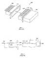
- FIG. 1illustrates an isometric of a conventional connector pair assembly 100 that utilizes the wiping form of contact.
- a female connector assembly 102is designed for compatible interface to a male connector assembly 104 .
- the female connector 102includes a number of female contacts 106 that come into operative contact with respective male contacts 108 of the male connector 104 when the connectors 102 and 104 are engaged.
- the male contact 108includes a bend feature 110 that is designed to enter into (and out of) contact with its respective female contact 106 by sliding along the corresponding female contact 106 when the connectors 102 and 104 are engaged (and disengaged).
- the bend feature 110 coming into contact with the respective female contact during engagement and disengagement of the connectors 102 and 104forms the wiping action on the metals of the two contacts 106 and 108 that in high cycle applications eventually wears away the contact plating on the surface on either or both of the contacts 106 and 108 .
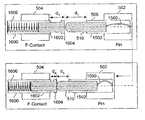
- FIG. 2there is illustrated a side view of the conventional connector pair of FIG. 1 incorporating the wiping style of contact.
- the male connector 104includes the male contact 108 with the bend feature 110 , and further, a contact lug 200 for permanently connecting a suitable wire thereto.
- the female connector 102includes the corresponding female contact 106 integrated therein such that when the connectors 102 and 104 are brought into engagement, an upper surface 112 of the bend feature 110 slidably engages a lower surface 202 of the female contact 106 for a short distance along the length of the female contact 106 to facilitate an electrical connection. This wiping action causes metal plating wear during the engagement process.
- FIG. 1 and FIG. 2are not necessarily to scale, or to a particular design, but are intended to simply show the general features of the wiping form of contacts in a conventional connector pair.
- Alignment of the male and female connectorsis also a common problem, particularly in pin-in-socket type connectors. Because of the intolerant stack-up associated with the terminal assembly and connector itself, compounded with a similar stack-up on the accessory side, alignment of the connector halves can be a serious issue. Pin-in-socket type connectors have the most significant alignment issue; if the pins and sockets are not accurately lined up, pins can be bent and/or broken off as the user attempts to force the two mating connector halves together.
- a male connector assembly 300is manufactured with one or more pin contacts 302
- a compatible female connector assembly 304includes one or more corresponding socket contacts 306 .
- the pin contacts 302slide into respective socket contacts 306 to facilitate an electrical connection.
- misalignment of any pin contact 302 to any socket contact 306can cause the user to twist or struggle with the connectors 300 and 304 in an attempt to align all of the pins to the respective sockets for full engagement of the connectors 300 and 304 .
- Such a systemnot only is susceptible to the alignment problem, but also contends with the contact plating wear problem associated with the wiping form of contact.
- the male connector 300includes the plated pin contact 302 , which pin contact 302 includes a pin head portion 400 that slides into a corresponding plated socket slot 402 of the socket contact 306 of the female connector 304 .
- This designis also burdened with wear of the contact plating on a surface 404 of the pin head portion 400 that comes into contact with an inside surface(s) 406 of the socket slot 402 , since the wiping action is present between the pin head portion 400 and the inside surface(s) 406 .
- the inside surface(s) 406 of the socket slot 402also exhibit plating wear in high cycle applications, which reduces the lifetime of the device in which such contact style is used.
- the present invention disclosed and claimed hereinin one aspect thereof, comprises a connector interface for a portable device.
- the portable device interfaceincludes an interface connector having an arrangement of one or more pogo-style contacts to facilitate conducting power and signals. Wearing of the pogo contacts and mating contacts of an accessory to which the portable device interfaces, is reduced substantially during engagement and disengagement of the portable device with the accessory.
- the portable devicecan include either the male component of the connector interface or the female component depending upon design choice, and the related accessory device include the counterpart component of the connector interface. Employment of such interface connector as part of the portable device facilitates extending device life-time and/or maintenance to the extent that such interface component exhibits less wear and tear than conventional connector interfaces currently employed in portable devices.
- a connector contact interface systemfor a portable device and an accessory.
- the portable deviceincludes a device connector having a first arrangement of one or more pogo contacts.
- the accessoryincludes an accessory connector adapted to mate to the device connector, the accessory connector having a second arrangement of accessory contacts that align with the one or more pogo contacts of the device connector. Wearing of the device contacts and accessory contacts is reduced substantially during engagement and disengagement of the portable device with the accessory because the device and accessory contacts are configured to be in axial alignment. When the connectors are in full engagement, they are axially aligned in tip-to-tip abutment.
- the device and/or the accessory contactsare included either on a rigid or flexible circuit board, or in connector housing.
- the contacts of either or both of the connectorsare plated with a wear-resistant metal such as hard gold.
- an accessory for the portable deviceadapted to interface thereto in accordance with the disclosed connector interface architecture.
- the accessoryincludes an arrangement of one or more pogo contacts for conducting at least one of power and signals.
- the one or more pogo contactsare in substantially axial alignment and tip-to-tip abutment with mating contacts of the portable device during engagement of the accessory with the portable device.
- the pogo contactsplated with a wear-resistant electrically conductive hard gold.
- the accessoryis operable to communicate signals wirelessly with the portable device during disengagement.
- FIG. 1illustrates an isometric of a conventional connector pair assembly that utilizes the wiping form of contact.
- FIG. 2illustrates a side view of the conventional connector pair of FIG. 1 incorporating the wiping style of contact.
- FIG. 3illustrates an isometric of a conventional pin-in-socket type of connector assembly.
- FIG. 4illustrates a side view of the conventional connector pair of FIG. 3 that incorporates the pin-in-socket style of contact.
- FIG. 5illustrates an isometric of an exemplary connector system, according to a disclosed embodiment.
- FIG. 6illustrates an alternative embodiment in which the female contacts are configured simply as an arrangement of the fixed conductive contact pads on a rigid circuit board (or flexible circuit board).
- FIG. 7illustrates an alternative embodiment in which the connector system of FIG. 5 includes a mixed arrangement of one or more pogo-style pins and one or more non-pogo pins.
- FIG. 8illustrates an alternative embodiment in which the connectors are circular in design, utilizing the disclosed interface system of FIG. 5 .
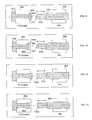
- FIG. 9illustrates a more detailed view of the relationship between the pogo-style pin and corresponding female contact for the connector system of FIG. 5 .
- FIG. 10illustrates a detailed view of an alternative embodiment where the head portion of the female contact used for contacting the pin head is recessed into the housing of the female connector.
- FIG. 11illustrates a detailed view of an alternative embodiment where the pogo-style pin has a flat tip.
- FIG. 12illustrates a detailed view of an alternative embodiment where the where the pogo-style pin has the flat tip and the female contact head is recessed into the housing of the female connector.
- FIG. 13illustrates a detailed view of an alternative embodiment where the pogo-style pin has the flat tip and the fixed female contact has a rounded head.
- FIG. 14illustrates a detailed view of an alternative embodiment where the pogo-style pin has the rounded pin head and the female contact has a head designed with a recessed conical concavity.
- FIG. 15illustrates positioning of the pin head portion of the pogo pin to the contact from an extended position in FIG. 15 a to a recoiled position in FIG. 15 b.
- FIG. 16illustrates positioning of both the pogo-style pin and a pogo-style contact from extended positions in FIG. 16 a to partially recoiled positions in FIG. 16 b during full connector engagement.
- FIG. 17illustrates a general block diagram of equipment that utilizes the disclosed connector system.
- FIG. 18illustrates front and rear views of a portable terminal device adapted to include the disclosed contact architecture.
- the disclosed inventionprovides a reliable tip-to-tip contact connector interface system for use in high cycle applications that substantially eliminates alignment and contact wear issues in connection with portable computing devices (e.g., mobile terminals).
- Suitable application of the connector systemincludes a wide variety of portable devices that interface with a base unit or station, such as handheld terminals, portable optical scanning devices, portable magnetic data readers, wireless telephones, and virtually any application requiring the interface of two set of opposing contacts.
- the system 500includes both a male connector 502 and a female connector 504 , each having an arrangement of electrically conductive contacts manufactured therein suitable for making an appropriate electrical connection according to the particular application.
- the male connector 502includes pin contacts 506 of a pogo style (e.g., a compressible recoilable spring probe or plunger) assembled in a predetermined arrangement within a plastic housing block 508 .
- the pogo contact 506includes a head portion 510 with a tip 511 that comes into a tip-to-tip abutment with a corresponding female contact 512 , when the connectors 502 and 504 are in full engagement.
- the female contact 512is intentionally oversized to allow for any misalignment that may occur. Thus the traditional alignment pegs that typically accompany either or both of the connectors ( 502 and 504 ) are not required.
- Both the pogo contact 506 and the female contact 512include a lug end (not shown) for connecting a wire or circuit track by crimping, soldering, or other techniques known to make such connections, to the device into which it is designed.
- the female contacts 512are a fixed style of contact (e.g., non-pogo style) that is assembled into a plastic housing connector block 514 .
- a contact end 516 of the female contact 512may have a wide exposed surface such that alignment with the tip 511 of the male head portion 510 is substantially assured during full engagement of the connectors 502 and 504 . This is illustrated in greater detail hereinbelow.
- the connector system 500is suitable for high cycle applications by offering a simple axial motion for this tip-to-tip contact style when mating the connectors 502 and 504 , which substantially reduces or eliminates alignment issues and plating wear for a high cycle life on the order of 100,000 insertion actions. That is, the user is assured of an operational electrical connection for each pin/pad pair when engaging the connectors 502 and 504 since there are no significant alignment issues and no substantial contact wear.
- the contacts of both connector halvescan be plated with a suitable wear-resistant electrically conductive hard metal material such as hard gold, which reduces or virtually eliminates the need for contact cleaning.
- the either or both of the connectors 502 and 504can contain pogo-style contacts. However, to keep costs low, it is preferable that only one of the connectors contains the pogo-type contacts, that being the male connector. Furthermore, where the application may find such a use, all the pogo contacts can be of one type, or a combination of different types of pogo contacts in the same connector.
- the female contacts 512are configured simply as an arrangement of the fixed conductive contact pads 600 on a rigid circuit board 602 (or flexible circuit board).
- the pads 600can be on an exposed portion of the circuit board of the portable device, such that when returned to the base station, cradle, or mating accessory, the portable device is situated to bring the pads 600 into an axial alignment 604 and tip-to-tip contact with the male connector pogo-style pin contacts 506 .
- a connector system 700(similar to connector system 500 ) includes a mixed arrangement of one or more of the pogo-style contacts 506 and corresponding oversized female contacts 705 .
- One or more non-pogo pins (or pegs) 702are also included in this implementation, but are not required.
- a male connector 704includes the non-pogo pin 702 that is an alignment peg that matches with a peg socket (or hole) 708 of a female connector 706 so that the user can more readily engaged the connectors 704 and 706 .
- other quick alignment connect or disconnect designscan be utilized in combination with the disclosed connector system 700 according to the particular application.
- the disclosed connector systemis not limited to all pogo-style contacts 506 , but can include an arrangement of one or more of the guide pegs 702 , one or more fixed pin connections, etc., with the pogo-style pins 506 .
- a circular male connector 800includes a mixed arrangement of one or more of the pogo-style contacts 506 , corresponding oversized female contacts 705 , and one or more non-pogo pins (or pegs) 702 .
- the male connector 800includes two non-pogo pins 702 (one not visible) that are alignment pegs matching with the respective peg sockets (or holes) 708 of a circular female connector 802 , so that the user can more readily engaged the connectors 800 and 802 .
- this circular connector arrangementdoes not need to use the alignment pegs 702 , since the use of the oversized female contacts 705 will compensate for any misalignment.
- other quick alignment connect or disconnect designscan be utilized in combination with the disclosed circular connector system according to the particular application.
- the disclosed circular connector systemis not limited to all pogo-style contacts 506 , but can include an arrangement of one or more of the guide pegs 702 , one or more fixed pin connections, etc., with the pogo-style pins 506 .
- FIG. 9there is illustrated a more detailed view of the relationship between the pogo-style pin 506 (denoted “Pin” in the illustration) and corresponding female contact 512 (denoted “F-Contact” in the illustration) for the connectors 502 and 504 of FIG. 5 .
- the location of the pin 506is designed into the male connector 502 to be in substantial axial alignment with the corresponding female contact 512 .
- the female contact 512 and the pogo pin 506are in axial alignment along a common central axis 900 .
- the female contact 512includes an oversized female contact head 902 (similar to contact end 516 ) whose contact surface area is sized equally or larger than the area of the pin head portion 510 to compensate for any misalignment along the axis 900 that may occur due to the high cycle lifetime.
- the pin head tip 511is assured of coming into tip-to-tip abutment with the contact head 902 of the female contact 512 when connectors 502 and 504 are engaged.
- the head portion 510has the tip 511 that is rounded to facilitate a single-point electrical connection no matter how misaligned the connectors 502 and 504 could be. Therefore, using the disclosed connector system architecture substantially eliminates the metal-to-metal wiping action exhibited in the prior art.
- the head configurations of the pogo style pin 506 and female contact head 902can be reversed such that the flatter style of female contact head 902 is part of the pogo pin 506 , and the round tip 511 is utilized on the female contact 512 .
- FIG. 10there is illustrated a detailed view of an alternative embodiment where the contact head 902 of the female contact 512 used for contacting the pin head portion 510 is recessed into the housing of the female connector 504 .
- the contact head 902is recessed into a recess 1000 of the housing of the connector 504 to facilitate guiding the pin head tip 511 into tip-to-tip contact with the contact head 902 .
- the walls of the recess 1000function to guide (or “funnel”) the tip 511 into contact with the recessed female contact head 902 .
- the housing of the female connector 504is typically constructed of a hard plastic, or the like, the metal plating of the pin head portion 510 will not be worn away from the wiping action of the head portion 510 against the plastic walls of the recess.
- the head portion 510has the rounded tip 511 to facilitate a single-point electrical connection no matter how misaligned the connectors 502 and 504 could be. This is to illustrate that the disclosed architecture can be implemented in a number of ways, even with recessed and oversized female contact heads 902 .
- FIG. 11there is illustrated a detailed view of an alternative embodiment where the pogo-style pin 506 has a flat tip 1100 . This is simply to indicate that the male connector 502 of disclosed connector system is not limited to a particular style of pogo pin.
- FIG. 12there is illustrated a detailed view of an alternative embodiment where the pogo-style pin 506 has the flat tip 1100 and the female contact head 902 is recessed into the housing of the female connector 504 . Again, this is simply to indicate that the female connector 504 of disclosed connector system is not limited to a particular style or design of fixed female contact 512 .
- FIG. 13there is illustrated a detailed view of an alternative embodiment where the pogo-style pin 506 has the flat tip 1100 and the fixed female contact 512 has a rounded head 1300 .
- FIG. 14there is illustrated a detailed view of an alternative embodiment where the pogo-style pin 506 has the rounded tip 511 on the pin head portion 510 and the female contact 512 has a head 1400 designed with a recessed conical concavity.
- This particular style of head 1400provides multipoint contact with the surface of the rounded male head tip 511 . Again, this is simply to indicate that the disclosed connector system is not limited to the style or design of fixed female contact 512 and pogo pin 506 .
- the pin 506includes a pin resilient member 1500 that forces the pin head portion 510 forward from within a pin shell 1502 of the pin assembly 506 .
- the tip 511 of the pin head portion 510is extended a distance d 1 from the end of the shell 1502 .
- the resilient member 1500is shown in a substantially extended position. In FIG.
- the male connector 502is brought into engagement with the female connector 504 causing the pin head portion 510 to recess into the shell 1502 .
- the resilient member 1500is then placed in a contracted position according to the degree of proximity of the male connector 502 with the female connector 504 .
- the pin head portion 510extends a distance d 2 from the end of the shell 1502 .
- the pogo contact 1600includes a shell 1602 that captures a movable contact head 1604 .
- a contact resilient member 1606which is a spring in this particular embodiment, provides a steady force to the contact head 1604 to ensure that the contact head 1604 is extended from the shell 1602 a distance d 3 when the connectors ( 502 and 504 ) are not engaged.
- the pin head portion 510is extended the distance d 1 when the connectors ( 502 and 504 ) are not engaged.
- the contact head 1604recesses back into the contact shell 1602 such that the head 1604 extends a distance d 4 from the end of the shell 1602 . Accordingly, the pin head portion 510 recesses into the pin shell 1502 such that the pin head 510 extends a distance d 5 from the end of the shell 1502 .
- Both the contact member 1606 and the pin member 1500are now under greater compression during full connector engagement. Moreover, the distances d 4 and d 5 are determined by the relative strengths of the respective members 1500 and 1606 .
- the pin member 1500is stronger than the contact member 1606 , the pin member 1500 will “overpower” the contact member to some extent until equilibrium is reached. Thus a reliable, electrically conductive interface is provided between the pin head 510 and the contact 1604 .
- a portable device 1700 and a base unit 1702interface via the connector system 500 .
- the device 1700includes a female connector 1704 (similar to connector 504 ) to accommodate signals and power of the base unit 1702 .
- the base unit 1702includes a compatible male connector 1706 that utilizes the pogo style of pins 506 .
- the portable device 1700may include a display 1708 for presenting information to the user, and an input pad 1710 for providing a means for the user to enter information to utilize the device 1700 , or configure the device 1700 .
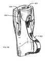
- FIG. 18there is illustrated front and rear views of a portable terminal device 1800 (similar to portable device 1700 ) adapted to include the disclosed contact architecture.
- FIG. 18 ais a pictorial representation the front view thereof
- FIG. 18 bis a pictorial representation of the rear view.
- the portable electronic device 1800is a hand-held terminal used in a wireless communication network for tracking inventory, scanning and storing data, etc.
- the usermay manually interface with the device 1800 via a keypad 1802 , automatically input data by reading a dataform (not shown) in the format of, e.g., bar code, image, magnetic media with a dataform reading component 1804 , the dataform reading component 1804 , including, e.g., a bar code scanner/imaging apparatus or magnetic reader, etc., the operation of all which can occur independent of the device 1800 being in operative wired/wireless communication with a network, e.g., a LAN or WAN.
- a networke.g., a LAN or WAN.
- the device 1800does not include wireless communication capability, e.g., an RF means, to provide for real time communications of data to the LAN/WAN, the data is stored in memory within the device 1800 .
- the memorycan take the form non-volatile storage such as a micro-drive disk storage unit, RAM memory, flash memory, etc.
- a network storage nodee.g., a network client or server computer (not shown).
- the portable device 1800can also be any other type of device that is portable in nature, and having electronic circuitry therein in accordance with the present invention.
- the portable devicecould be a laptop computer, notebook computer, a Personal Data Assistant, cellular telephone, pager, any of which employs an onboard power source, such as batteries.
- the device 1800includes, but is not limited to, the following components: a housing 1806 for providing a ruggedized enclosure in which the device hardware and software are contained; a power button 1807 turning the device on and off; a display 1808 for displaying information to a user, and where the display 1808 is an interactive interface device such as a touch screen display, allowing the user to interact manually to input information and/or operational commands; the keypad 1802 including a set of user interface keys for facilitating to input of information and/or operational commands by the user, the keypad 1802 including full alphanumeric capability, function keys, control keys, etc.; the dataform reading device 1804 , e.g., bar code scanner, imager, magnetic medium reader, etc.; a microphone 1810 for receiving audio input; a speaker for providing audio output to the user, whether rudimentary beeps or modulated verbal signals; and, one or more communication ports, either provided separately through the housing 1806 , and/or via a mating connector 1814 incorporating the disclosed contact architecture.
- the connector 1814mates to a base connector 1815 of a base station 1817 , or other suitable accessory.
- the connectors( 1814 and 1815 ) may be either a male connector or female connectors utilizing the disclosed contact architecture and arrangement of any of the connectors 502 , 504 , 600 , 704 , 706 , 800 , 802 provided herein.
- the base station 1817provides charging power to batteries of the device 1800 , and power to operate the device 1800 while in the station 1817 , if adapted to do so.
- the station 1817is also operable to communicate wirelessly with the portable device 1800 when the device 1800 is disengaged from the station 1817 .
- the station 1817includes a cable 1819 that accommodates both power and communications.
- the cable 1819can be a wired network connection such that data may uploaded/downloaded between a network resource and the device 1800 . It is appreciated that other arrangements of the disclosed contact architecture thereof can be incorporated therein.
- the device 1800can include a lighting element such as an LED that is illuminated to signal whether or not the dataform has been successfully read.
- the housing 1806is an elongated enclosure of a size and structure that includes contours so as to fit conveniently into the open palm of the user.
- the housing 1806may be comprised of a number of mating shell portions such as, for example, a front shell 1816 and rear shell 1818 , as well as a battery pack lid 1820 .
- the housing 1806is illustrated to include a hand strap 1822 for user comfort, and to aid the user in retaining the device 1800 in his or her hand.
- the device 1800also includes a window 1824 through which the dataform reader 1804 is able to read the dataform of a label or object presented for reading.
- a pen 1826is provided in a pen holder 1828 .
- I 2 CInter-IC bus
- RS-232Universal Serial Bus
- IEEE 1394also known as FireWireTM
Landscapes
- Coupling Device And Connection With Printed Circuit (AREA)
- Telephone Set Structure (AREA)
Abstract
Description
Claims (22)
Priority Applications (6)
| Application Number | Priority Date | Filing Date | Title |
|---|---|---|---|
| US10/317,452US6878016B2 (en) | 2002-12-12 | 2002-12-12 | High cycle connector contact system |
| AU2003295443AAU2003295443B2 (en) | 2002-12-12 | 2003-11-10 | High cycle connector contact system |
| CA002509376ACA2509376A1 (en) | 2002-12-12 | 2003-11-10 | High cycle connector contact system |
| PCT/US2003/035766WO2004055945A1 (en) | 2002-12-12 | 2003-11-10 | High cycle connector contact system |
| JP2004560310AJP2006511905A (en) | 2002-12-12 | 2003-11-10 | Connector contact system for multi-cycle |
| EP03786629AEP1570547A4 (en) | 2002-12-12 | 2003-11-10 | High cycle connector contact system |
Applications Claiming Priority (1)
| Application Number | Priority Date | Filing Date | Title |
|---|---|---|---|
| US10/317,452US6878016B2 (en) | 2002-12-12 | 2002-12-12 | High cycle connector contact system |
Publications (2)
| Publication Number | Publication Date |
|---|---|
| US20040115994A1 US20040115994A1 (en) | 2004-06-17 |
| US6878016B2true US6878016B2 (en) | 2005-04-12 |
Family
ID=32506123
Family Applications (1)
| Application Number | Title | Priority Date | Filing Date |
|---|---|---|---|
| US10/317,452Expired - LifetimeUS6878016B2 (en) | 2002-12-12 | 2002-12-12 | High cycle connector contact system |
Country Status (6)
| Country | Link |
|---|---|
| US (1) | US6878016B2 (en) |
| EP (1) | EP1570547A4 (en) |
| JP (1) | JP2006511905A (en) |
| AU (1) | AU2003295443B2 (en) |
| CA (1) | CA2509376A1 (en) |
| WO (1) | WO2004055945A1 (en) |
Cited By (26)
| Publication number | Priority date | Publication date | Assignee | Title |
|---|---|---|---|---|
| US20060046579A1 (en)* | 2004-09-01 | 2006-03-02 | Edwards Systems Technology (Est) | Nurse call connector system and method |
| US20060046578A1 (en)* | 2004-09-01 | 2006-03-02 | Edwards Systems Technology (Est) | Nurse call connector system and method |
| US7075270B1 (en)* | 2003-07-16 | 2006-07-11 | Plantronics, Inc. | Charger contact |
| US20070117426A1 (en)* | 2005-11-23 | 2007-05-24 | Slobadan Pavlovic | Power supply circuit for removable automotive interior systems with integrated switching function |
| US20070224889A1 (en)* | 2004-05-17 | 2007-09-27 | Wako Seiki Co., Ltd. | Conductor Pin |
| US20090103249A1 (en)* | 2007-09-26 | 2009-04-23 | Daniella Strat | Integrated Frame for Monocoque Housing |
| US20100112830A1 (en)* | 2008-10-30 | 2010-05-06 | Kabushiki Kaisha Toshiba | Stacking connector and electronic device |
| US20110234160A1 (en)* | 2010-03-29 | 2011-09-29 | Smith Stephen J | Battery charger for charging batteries of different sizes |
| US20130137298A1 (en)* | 2009-09-17 | 2013-05-30 | Matthew Leigh Vroom | Docking Station for an Electronic Device with Improved Electrical Interface |
| US20130189857A1 (en)* | 2012-01-23 | 2013-07-25 | Lenovo (Singapore) Pte. Ltd. | Logo connector |
| US9166334B1 (en)* | 2014-04-11 | 2015-10-20 | Chicony Electronics Co., Ltd. | Slide connector, slide socket and electronic device for electrical connecting with slide connector |
| US9285831B2 (en) | 2009-09-17 | 2016-03-15 | Henge Docks Llc | Docking station for portable electronics |
| US9309698B2 (en) | 2013-12-31 | 2016-04-12 | Henge Docks Llc | Motorized horizontal docking station having integrated locking mechanism |
| US9575510B1 (en) | 2015-10-23 | 2017-02-21 | Matthew Leigh Vroom | Precision docking station for an electronic device having integrated retention mechanism |
| US9727084B2 (en) | 2015-10-23 | 2017-08-08 | Henge Docks Llc | Drivetrain for a motorized docking station |
| US9811118B2 (en) | 2015-10-23 | 2017-11-07 | Henge Docks Llc | Secure assembly for a docking station |
| US9927838B2 (en) | 2013-12-31 | 2018-03-27 | Henge Docks Llc | Sensor system for docking station |
| US20180131115A1 (en)* | 2015-04-21 | 2018-05-10 | Varian Semiconductor Equipment Associates, Inc. | Thermally insulating electrical contact probe |
| US20190123498A1 (en)* | 2015-09-30 | 2019-04-25 | Raytheon Company | Coaxial Electrical Interconnect |
| US10365688B1 (en) | 2018-04-19 | 2019-07-30 | Henge Docks Llc | Alignment sleeve for docking station |
| US20200161788A1 (en)* | 2018-11-21 | 2020-05-21 | Inventec (Pudong) Technology Corporation | Electrical connector assembly |
| US10859286B2 (en) | 2015-11-30 | 2020-12-08 | Blender Products, Inc. | Combined economizer and mixer for air handling unit |
| US11287157B2 (en) | 2015-11-30 | 2022-03-29 | Blender Products, Inc. | Combined economizer and mixer for air handling unit |
| US11326794B2 (en) | 2015-11-30 | 2022-05-10 | Blender Products, Inc. | Combined economizer and mixer for air handling unit |
| US20220190499A1 (en)* | 2019-03-25 | 2022-06-16 | Harting Electric Gmbh & Co. Kg | Plug connector |
| US11379004B2 (en) | 2018-08-08 | 2022-07-05 | Hewlett-Packard Development Company, L.P. | Adjustment control mechanisms of pogo pins |
Families Citing this family (34)
| Publication number | Priority date | Publication date | Assignee | Title |
|---|---|---|---|---|
| DE102004011648A1 (en)* | 2004-03-10 | 2005-09-29 | Roche Diagnostics Gmbh | Test element analysis system with hard-coated contact surfaces |
| US7498826B2 (en)* | 2006-08-25 | 2009-03-03 | Interconnect Devices, Inc. | Probe array wafer |
| DE102006052112A1 (en)* | 2006-11-06 | 2008-05-08 | Robert Bosch Gmbh | Electrical contact arrangement |
| US20090111320A1 (en)* | 2007-10-30 | 2009-04-30 | Sony Ericsson Mobile Communications Ab | Enhanced universal serial bus connector |
| EP2391991A1 (en)* | 2009-01-30 | 2011-12-07 | Atek Products, LLC | Data carrier system having a compact footprint and methods of manufacturing the same |
| US8052470B1 (en)* | 2011-01-12 | 2011-11-08 | Cheng Uei Precision Industry Co., Ltd. | Probe connector |
| US8182288B1 (en)* | 2011-02-18 | 2012-05-22 | Chen Uei Precision Industry Co., Ltd. | Probe connector |
| US8494585B2 (en) | 2011-10-13 | 2013-07-23 | The Boeing Company | Portable communication devices with accessory functions and related methods |
| US9354748B2 (en) | 2012-02-13 | 2016-05-31 | Microsoft Technology Licensing, Llc | Optical stylus interaction |
| US9870066B2 (en) | 2012-03-02 | 2018-01-16 | Microsoft Technology Licensing, Llc | Method of manufacturing an input device |
| US9460029B2 (en) | 2012-03-02 | 2016-10-04 | Microsoft Technology Licensing, Llc | Pressure sensitive keys |
| US8873227B2 (en) | 2012-03-02 | 2014-10-28 | Microsoft Corporation | Flexible hinge support layer |
| US9298236B2 (en) | 2012-03-02 | 2016-03-29 | Microsoft Technology Licensing, Llc | Multi-stage power adapter configured to provide a first power level upon initial connection of the power adapter to the host device and a second power level thereafter upon notification from the host device to the power adapter |
| US9075566B2 (en) | 2012-03-02 | 2015-07-07 | Microsoft Technoogy Licensing, LLC | Flexible hinge spine |
| US20130300590A1 (en) | 2012-05-14 | 2013-11-14 | Paul Henry Dietz | Audio Feedback |
| US8964379B2 (en) | 2012-08-20 | 2015-02-24 | Microsoft Corporation | Switchable magnetic lock |
| JP2016507841A (en)* | 2013-01-30 | 2016-03-10 | マイクロソフト テクノロジー ライセンシング,エルエルシー | Electrical contacts and connectors |
| CN105592767B (en)* | 2013-06-28 | 2018-04-03 | 恩多巧爱思股份有限公司 | Multi-viewing element endoscopy system with modular imaging unit |
| US9257764B2 (en)* | 2014-01-16 | 2016-02-09 | International Business Machines Corporation | Low insertion force connector utilizing directional adhesion |
| US10120420B2 (en) | 2014-03-21 | 2018-11-06 | Microsoft Technology Licensing, Llc | Lockable display and techniques enabling use of lockable displays |
| DE102014009821B4 (en)* | 2014-07-02 | 2017-01-12 | Robert Virant | Multi-core electrical spring pin connector |
| US10324733B2 (en) | 2014-07-30 | 2019-06-18 | Microsoft Technology Licensing, Llc | Shutdown notifications |
| TWI539884B (en)* | 2015-01-26 | 2016-06-21 | 宏碁股份有限公司 | Electronic device |
| KR200484059Y1 (en)* | 2015-07-03 | 2017-07-25 | 세파전자(소주)유한공사 | Protecting case for portable device using connetion tip |
| US10299969B2 (en)* | 2015-10-06 | 2019-05-28 | Convergence Systems Limited | Diaper |
| US10134489B2 (en)* | 2015-10-06 | 2018-11-20 | Convergence Systems Limited | Medical pad and a wetness reporting system with such a medical pad |
| JP6366622B2 (en)* | 2016-02-24 | 2018-08-01 | 株式会社フジクラ | Terminal connection structure and electrical connector |
| CN106235994A (en)* | 2016-08-31 | 2016-12-21 | 深圳开立生物医疗科技股份有限公司 | A kind of adapter and endoscopic system |
| CN108695619B (en)* | 2017-04-05 | 2021-07-20 | 富士康(昆山)电脑接插件有限公司 | Plug connector and combination thereof |
| WO2018186524A1 (en)* | 2017-04-07 | 2018-10-11 | 주식회사 아이리버 | Modular signal conversion apparatus and method |
| KR102300544B1 (en)* | 2017-04-07 | 2021-09-09 | (주)드림어스컴퍼니 | Modularized Signal Converting Apparatus and Method thereof |
| TWI697814B (en)* | 2018-07-16 | 2020-07-01 | 禾瑞亞科技股份有限公司 | Functional modular touch pen |
| US10903612B1 (en)* | 2019-06-26 | 2021-01-26 | Amazon Technologies, Inc. | Dock device with integrated clamp |
| JP7703895B2 (en)* | 2021-05-17 | 2025-07-08 | 日本電気株式会社 | Superconducting Devices |
Citations (12)
| Publication number | Priority date | Publication date | Assignee | Title |
|---|---|---|---|---|
| US3431428A (en)* | 1967-04-19 | 1969-03-04 | Andrew F Van Valer | Safety vehicle power distribution system |
| US4734050A (en)* | 1985-06-07 | 1988-03-29 | Societe Nouvelle De Connexion | Universal connection unit |
| US5542015A (en)* | 1993-04-08 | 1996-07-30 | The Whitaker Corporation | Optical fiber connector latching mechanism |
| US5749754A (en)* | 1996-07-19 | 1998-05-12 | Ericsson, Inc. | Radiotelephone having a combination fastener and electrical connector |
| US6039580A (en)* | 1998-07-16 | 2000-03-21 | Raytheon Company | RF connector having a compliant contact |
| US6261130B1 (en)* | 2000-01-19 | 2001-07-17 | Mhl Development Company, Inc. | High-density pogo pin connector |
| US6280258B1 (en)* | 1998-02-26 | 2001-08-28 | Telefonaktiebolaget Lm Ericsson (Publ) | Arrangements relating to electrical connections between apparatuses containing electrical circuitry |
| US20010046801A1 (en)* | 2000-05-18 | 2001-11-29 | Joe Tate | ESD protective connector apparatus |
| US6450828B1 (en)* | 2000-06-01 | 2002-09-17 | Rosen Products Llc | Projecting plug with non-wiping connector contacts |
| US6653562B2 (en)* | 2001-10-18 | 2003-11-25 | Pent Products, Inc. | Portable electrical unit |
| US20030220022A1 (en)* | 2002-05-24 | 2003-11-27 | Dean Kawaguchi | Connection of a user identity module to a compact card case |
| US20040002243A1 (en)* | 2002-06-27 | 2004-01-01 | Vocollect, Inc. | Break-away electrical connector |
Family Cites Families (9)
| Publication number | Priority date | Publication date | Assignee | Title |
|---|---|---|---|---|
| JPH03123749U (en)* | 1990-03-30 | 1991-12-16 | ||
| JPH0615362U (en)* | 1992-06-30 | 1994-02-25 | 株式会社東芝 | Electronics |
| US5641315A (en)* | 1995-11-16 | 1997-06-24 | Everett Charles Technologies, Inc. | Telescoping spring probe |
| US6305963B1 (en)* | 1996-08-16 | 2001-10-23 | Agilent Technologies, Inc. | Push-lock BNC connector |
| JPH11168536A (en)* | 1997-12-05 | 1999-06-22 | Toshiba Corp | Portable electronic devices |
| US6079999A (en)* | 1998-05-08 | 2000-06-27 | Hewlett-Packard Company | Single action mechanical/electrical circuit card engagement mechanism |
| US6283777B1 (en)* | 1999-05-26 | 2001-09-04 | Palm, Inc. | Dual style connector for handheld computer |
| JP3564375B2 (en)* | 2000-09-20 | 2004-09-08 | Necアクセステクニカ株式会社 | Instantaneous interruption detection device for connection terminals |
| JP2002246097A (en)* | 2001-02-19 | 2002-08-30 | Matsushita Electric Ind Co Ltd | Electrical connection device, electrical connection method, and component mounting device |
- 2002
- 2002-12-12USUS10/317,452patent/US6878016B2/ennot_activeExpired - Lifetime
- 2003
- 2003-11-10EPEP03786629Apatent/EP1570547A4/ennot_activeWithdrawn
- 2003-11-10AUAU2003295443Apatent/AU2003295443B2/ennot_activeCeased
- 2003-11-10JPJP2004560310Apatent/JP2006511905A/enactivePending
- 2003-11-10CACA002509376Apatent/CA2509376A1/ennot_activeAbandoned
- 2003-11-10WOPCT/US2003/035766patent/WO2004055945A1/enactiveApplication Filing
Patent Citations (12)
| Publication number | Priority date | Publication date | Assignee | Title |
|---|---|---|---|---|
| US3431428A (en)* | 1967-04-19 | 1969-03-04 | Andrew F Van Valer | Safety vehicle power distribution system |
| US4734050A (en)* | 1985-06-07 | 1988-03-29 | Societe Nouvelle De Connexion | Universal connection unit |
| US5542015A (en)* | 1993-04-08 | 1996-07-30 | The Whitaker Corporation | Optical fiber connector latching mechanism |
| US5749754A (en)* | 1996-07-19 | 1998-05-12 | Ericsson, Inc. | Radiotelephone having a combination fastener and electrical connector |
| US6280258B1 (en)* | 1998-02-26 | 2001-08-28 | Telefonaktiebolaget Lm Ericsson (Publ) | Arrangements relating to electrical connections between apparatuses containing electrical circuitry |
| US6039580A (en)* | 1998-07-16 | 2000-03-21 | Raytheon Company | RF connector having a compliant contact |
| US6261130B1 (en)* | 2000-01-19 | 2001-07-17 | Mhl Development Company, Inc. | High-density pogo pin connector |
| US20010046801A1 (en)* | 2000-05-18 | 2001-11-29 | Joe Tate | ESD protective connector apparatus |
| US6450828B1 (en)* | 2000-06-01 | 2002-09-17 | Rosen Products Llc | Projecting plug with non-wiping connector contacts |
| US6653562B2 (en)* | 2001-10-18 | 2003-11-25 | Pent Products, Inc. | Portable electrical unit |
| US20030220022A1 (en)* | 2002-05-24 | 2003-11-27 | Dean Kawaguchi | Connection of a user identity module to a compact card case |
| US20040002243A1 (en)* | 2002-06-27 | 2004-01-01 | Vocollect, Inc. | Break-away electrical connector |
Non-Patent Citations (1)
| Title |
|---|
| International Search Report, PCT/US03/35766, mailed May 20, 2004. |
Cited By (43)
| Publication number | Priority date | Publication date | Assignee | Title |
|---|---|---|---|---|
| US7075270B1 (en)* | 2003-07-16 | 2006-07-11 | Plantronics, Inc. | Charger contact |
| US7585194B2 (en)* | 2004-05-17 | 2009-09-08 | Wako Seiki Co., Ltd. | Conductor pin |
| US20070224889A1 (en)* | 2004-05-17 | 2007-09-27 | Wako Seiki Co., Ltd. | Conductor Pin |
| US20060046578A1 (en)* | 2004-09-01 | 2006-03-02 | Edwards Systems Technology (Est) | Nurse call connector system and method |
| US7081024B2 (en)* | 2004-09-01 | 2006-07-25 | Gensus | Electrical connector system and method involving positive mating and flex release |
| US7160133B2 (en)* | 2004-09-01 | 2007-01-09 | Gencsus | Nurse call connector system and method |
| US20060046579A1 (en)* | 2004-09-01 | 2006-03-02 | Edwards Systems Technology (Est) | Nurse call connector system and method |
| US20070117426A1 (en)* | 2005-11-23 | 2007-05-24 | Slobadan Pavlovic | Power supply circuit for removable automotive interior systems with integrated switching function |
| US7322861B2 (en) | 2005-11-23 | 2008-01-29 | Lear Corporation | Power supply circuit for removable automotive interior systems with integrated switching function |
| US20090103249A1 (en)* | 2007-09-26 | 2009-04-23 | Daniella Strat | Integrated Frame for Monocoque Housing |
| US20100112830A1 (en)* | 2008-10-30 | 2010-05-06 | Kabushiki Kaisha Toshiba | Stacking connector and electronic device |
| US7819673B2 (en)* | 2008-10-30 | 2010-10-26 | Kabushiki Kaisha Toshiba | Stacking connector and electronic device |
| US20130137298A1 (en)* | 2009-09-17 | 2013-05-30 | Matthew Leigh Vroom | Docking Station for an Electronic Device with Improved Electrical Interface |
| US8512080B2 (en)* | 2009-09-17 | 2013-08-20 | Henge Docks Llc | Docking station for an electronic device with improved electrical interface |
| US9285831B2 (en) | 2009-09-17 | 2016-03-15 | Henge Docks Llc | Docking station for portable electronics |
| US20110234160A1 (en)* | 2010-03-29 | 2011-09-29 | Smith Stephen J | Battery charger for charging batteries of different sizes |
| US20130189857A1 (en)* | 2012-01-23 | 2013-07-25 | Lenovo (Singapore) Pte. Ltd. | Logo connector |
| US8740630B2 (en)* | 2012-01-23 | 2014-06-03 | Lenovo (Singapore) Pte. Ltd. | Logo connector |
| US9347245B2 (en) | 2013-12-31 | 2016-05-24 | Henge Docks Llc | Motorized horizontal docking station having integrated locking mechanism |
| US9725930B2 (en) | 2013-12-31 | 2017-08-08 | Henge Docks Llc | Motorized horizontal docking station having integrated locking mechanism |
| US10459486B2 (en) | 2013-12-31 | 2019-10-29 | Brydge Technologies LLC | Motorized horizontal docking station having integrated locking mechanism |
| US9309698B2 (en) | 2013-12-31 | 2016-04-12 | Henge Docks Llc | Motorized horizontal docking station having integrated locking mechanism |
| US9593510B2 (en) | 2013-12-31 | 2017-03-14 | Henge Docks Llc | Motorized horizontal docking station having integrated locking mechanism |
| US9650814B2 (en) | 2013-12-31 | 2017-05-16 | Henge Docks Llc | Alignment and drive system for motorized horizontal docking station |
| US9663977B2 (en) | 2013-12-31 | 2017-05-30 | Henge Docks Llc | Motorized horizontal docking station having integrated locking mechanism |
| US9927838B2 (en) | 2013-12-31 | 2018-03-27 | Henge Docks Llc | Sensor system for docking station |
| US9166334B1 (en)* | 2014-04-11 | 2015-10-20 | Chicony Electronics Co., Ltd. | Slide connector, slide socket and electronic device for electrical connecting with slide connector |
| US20180131115A1 (en)* | 2015-04-21 | 2018-05-10 | Varian Semiconductor Equipment Associates, Inc. | Thermally insulating electrical contact probe |
| US10826218B2 (en)* | 2015-04-21 | 2020-11-03 | Varian Semiconductor Equipment Associates, Inc. | Thermally insulating electrical contact probe |
| US10693266B2 (en)* | 2015-09-30 | 2020-06-23 | Raytheon Company | Coaxial electrical interconnect |
| US20190123498A1 (en)* | 2015-09-30 | 2019-04-25 | Raytheon Company | Coaxial Electrical Interconnect |
| US9727084B2 (en) | 2015-10-23 | 2017-08-08 | Henge Docks Llc | Drivetrain for a motorized docking station |
| US9811118B2 (en) | 2015-10-23 | 2017-11-07 | Henge Docks Llc | Secure assembly for a docking station |
| US9575510B1 (en) | 2015-10-23 | 2017-02-21 | Matthew Leigh Vroom | Precision docking station for an electronic device having integrated retention mechanism |
| US10859286B2 (en) | 2015-11-30 | 2020-12-08 | Blender Products, Inc. | Combined economizer and mixer for air handling unit |
| US11287157B2 (en) | 2015-11-30 | 2022-03-29 | Blender Products, Inc. | Combined economizer and mixer for air handling unit |
| US11326794B2 (en) | 2015-11-30 | 2022-05-10 | Blender Products, Inc. | Combined economizer and mixer for air handling unit |
| US10365688B1 (en) | 2018-04-19 | 2019-07-30 | Henge Docks Llc | Alignment sleeve for docking station |
| US11379004B2 (en) | 2018-08-08 | 2022-07-05 | Hewlett-Packard Development Company, L.P. | Adjustment control mechanisms of pogo pins |
| CN111211430A (en)* | 2018-11-21 | 2020-05-29 | 英业达科技有限公司 | Electrical connector assembly |
| US20200161788A1 (en)* | 2018-11-21 | 2020-05-21 | Inventec (Pudong) Technology Corporation | Electrical connector assembly |
| US20220190499A1 (en)* | 2019-03-25 | 2022-06-16 | Harting Electric Gmbh & Co. Kg | Plug connector |
| US11646517B2 (en)* | 2019-03-25 | 2023-05-09 | Harting Electric Stiftung & Co. Kg | Plug connector |
Also Published As
| Publication number | Publication date |
|---|---|
| AU2003295443B2 (en) | 2009-02-26 |
| WO2004055945A1 (en) | 2004-07-01 |
| EP1570547A1 (en) | 2005-09-07 |
| US20040115994A1 (en) | 2004-06-17 |
| EP1570547A4 (en) | 2007-08-22 |
| CA2509376A1 (en) | 2004-07-01 |
| AU2003295443A1 (en) | 2004-07-09 |
| JP2006511905A (en) | 2006-04-06 |
Similar Documents
| Publication | Publication Date | Title |
|---|---|---|
| US6878016B2 (en) | High cycle connector contact system | |
| KR100662339B1 (en) | Connection terminal of portable electric appliance | |
| US6592385B1 (en) | Card ejection mechanism for electronic card connector | |
| US6529714B1 (en) | Radio communication equipment | |
| US20190137948A1 (en) | Watch Module Connector | |
| US7956577B2 (en) | Holding base and information processing system | |
| US7364475B2 (en) | Spring based continuity alignment apparatus and method | |
| KR19990081579A (en) | Connector assembly | |
| US7473115B2 (en) | Memory card connector with improved switch structure | |
| JP2006511905A5 (en) | ||
| JP2002164120A (en) | Personal digital assistant device | |
| HUP0100451A2 (en) | Removable battery cover | |
| US6669493B2 (en) | Card connector unit provided with first accomodating position and second accomodating position | |
| US20060089032A1 (en) | Electrical card connector | |
| US20050245136A1 (en) | Memory card connector with metal cover and ground terminals | |
| US6217352B1 (en) | Electrical connectors having dual biased contact pins | |
| CN111082255A (en) | Connector and data line | |
| US10181690B1 (en) | Mobile device adapter | |
| US20050245120A1 (en) | Memory card connector with hinged and latched cover | |
| JP5924177B2 (en) | Cradle | |
| JPH1021350A (en) | Contactless memory card, card using terminal, and adapter device | |
| CN206892568U (en) | Wearable electronic device and accessory thereof | |
| CN218867513U (en) | Instrument connection structure | |
| KR101053465B1 (en) | Gender for Mobile Devices | |
| US10840629B2 (en) | Edge card adapter and electrical coupling device |
Legal Events
| Date | Code | Title | Description |
|---|---|---|---|
| AS | Assignment | Owner name:SYMBOL TECHNOLOGIES, INC., NEW YORK Free format text:ASSIGNMENT OF ASSIGNORS INTEREST;ASSIGNORS:WULFF, THOMAS;BELLOWS, DAVID E.;REEL/FRAME:013741/0514 Effective date:20030203 | |
| STCF | Information on status: patent grant | Free format text:PATENTED CASE | |
| FPAY | Fee payment | Year of fee payment:4 | |
| FPAY | Fee payment | Year of fee payment:8 | |
| AS | Assignment | Owner name:MORGAN STANLEY SENIOR FUNDING, INC. AS THE COLLATERAL AGENT, MARYLAND Free format text:SECURITY AGREEMENT;ASSIGNORS:ZIH CORP.;LASER BAND, LLC;ZEBRA ENTERPRISE SOLUTIONS CORP.;AND OTHERS;REEL/FRAME:034114/0270 Effective date:20141027 Owner name:MORGAN STANLEY SENIOR FUNDING, INC. AS THE COLLATE Free format text:SECURITY AGREEMENT;ASSIGNORS:ZIH CORP.;LASER BAND, LLC;ZEBRA ENTERPRISE SOLUTIONS CORP.;AND OTHERS;REEL/FRAME:034114/0270 Effective date:20141027 | |
| AS | Assignment | Owner name:SYMBOL TECHNOLOGIES, LLC, NEW YORK Free format text:CHANGE OF NAME;ASSIGNOR:SYMBOL TECHNOLOGIES, INC.;REEL/FRAME:036083/0640 Effective date:20150410 | |
| AS | Assignment | Owner name:SYMBOL TECHNOLOGIES, INC., NEW YORK Free format text:RELEASE BY SECURED PARTY;ASSIGNOR:MORGAN STANLEY SENIOR FUNDING, INC.;REEL/FRAME:036371/0738 Effective date:20150721 | |
| FPAY | Fee payment | Year of fee payment:12 |