US6876920B1 - Vehicle positioning apparatus and method - Google Patents
Vehicle positioning apparatus and methodDownload PDFInfo
- Publication number
- US6876920B1 US6876920B1US09/830,479US83047901AUS6876920B1US 6876920 B1US6876920 B1US 6876920B1US 83047901 AUS83047901 AUS 83047901AUS 6876920 B1US6876920 B1US 6876920B1
- Authority
- US
- United States
- Prior art keywords
- vehicle
- data
- tractor
- paths
- guidance
- Prior art date
- Legal status (The legal status is an assumption and is not a legal conclusion. Google has not performed a legal analysis and makes no representation as to the accuracy of the status listed.)
- Expired - Lifetime
Links
- 238000000034methodMethods0.000titledescription6
- 238000013479data entryMethods0.000claimsdescription12
- 238000012545processingMethods0.000claimsdescription10
- 230000005355Hall effectEffects0.000claimsdescription4
- 238000012937correctionMethods0.000claimsdescription3
- 230000000007visual effectEffects0.000abstractdescription12
- 230000000694effectsEffects0.000description9
- 230000009471actionEffects0.000description8
- 239000013598vectorSubstances0.000description8
- 238000010586diagramMethods0.000description5
- 230000005540biological transmissionEffects0.000description4
- 230000006854communicationEffects0.000description4
- 238000004891communicationMethods0.000description4
- 230000004044responseEffects0.000description4
- 238000004364calculation methodMethods0.000description3
- 230000008859changeEffects0.000description3
- 238000009313farmingMethods0.000description3
- 230000004907fluxEffects0.000description3
- 230000006870functionEffects0.000description3
- 230000007246mechanismEffects0.000description3
- 230000008569processEffects0.000description3
- 230000008878couplingEffects0.000description2
- 238000010168coupling processMethods0.000description2
- 238000005859coupling reactionMethods0.000description2
- 238000010348incorporationMethods0.000description2
- 238000013507mappingMethods0.000description2
- 230000001133accelerationEffects0.000description1
- 238000013459approachMethods0.000description1
- 230000007175bidirectional communicationEffects0.000description1
- 244000038559crop plantsSpecies0.000description1
- 238000005516engineering processMethods0.000description1
- 239000000446fuelSubstances0.000description1
- 238000003306harvestingMethods0.000description1
- 238000004519manufacturing processMethods0.000description1
- 238000012986modificationMethods0.000description1
- 230000004048modificationEffects0.000description1
- 238000012544monitoring processMethods0.000description1
- 239000000575pesticideSubstances0.000description1
- 230000000644propagated effectEffects0.000description1
- 238000012552reviewMethods0.000description1
- 238000005096rolling processMethods0.000description1
- 230000001932seasonal effectEffects0.000description1
- 238000000926separation methodMethods0.000description1
- 238000009331sowingMethods0.000description1
- 238000012360testing methodMethods0.000description1
- 230000036962time dependentEffects0.000description1
Images


Classifications
- A—HUMAN NECESSITIES
- A01—AGRICULTURE; FORESTRY; ANIMAL HUSBANDRY; HUNTING; TRAPPING; FISHING
- A01B—SOIL WORKING IN AGRICULTURE OR FORESTRY; PARTS, DETAILS, OR ACCESSORIES OF AGRICULTURAL MACHINES OR IMPLEMENTS, IN GENERAL
- A01B69/00—Steering of agricultural machines or implements; Guiding agricultural machines or implements on a desired track
- G—PHYSICS
- G05—CONTROLLING; REGULATING
- G05D—SYSTEMS FOR CONTROLLING OR REGULATING NON-ELECTRIC VARIABLES
- G05D1/00—Control of position, course, altitude or attitude of land, water, air or space vehicles, e.g. using automatic pilots
- G05D1/02—Control of position or course in two dimensions
- G05D1/021—Control of position or course in two dimensions specially adapted to land vehicles
- G05D1/0276—Control of position or course in two dimensions specially adapted to land vehicles using signals provided by a source external to the vehicle
- G05D1/0278—Control of position or course in two dimensions specially adapted to land vehicles using signals provided by a source external to the vehicle using satellite positioning signals, e.g. GPS
- G—PHYSICS
- G05—CONTROLLING; REGULATING
- G05D—SYSTEMS FOR CONTROLLING OR REGULATING NON-ELECTRIC VARIABLES
- G05D1/00—Control of position, course, altitude or attitude of land, water, air or space vehicles, e.g. using automatic pilots
- G05D1/02—Control of position or course in two dimensions
- G05D1/021—Control of position or course in two dimensions specially adapted to land vehicles
- G05D1/0212—Control of position or course in two dimensions specially adapted to land vehicles with means for defining a desired trajectory
- G05D1/0219—Control of position or course in two dimensions specially adapted to land vehicles with means for defining a desired trajectory ensuring the processing of the whole working surface
- G—PHYSICS
- G05—CONTROLLING; REGULATING
- G05D—SYSTEMS FOR CONTROLLING OR REGULATING NON-ELECTRIC VARIABLES
- G05D1/00—Control of position, course, altitude or attitude of land, water, air or space vehicles, e.g. using automatic pilots
- G05D1/02—Control of position or course in two dimensions
- G05D1/021—Control of position or course in two dimensions specially adapted to land vehicles
- G05D1/0268—Control of position or course in two dimensions specially adapted to land vehicles using internal positioning means
- G05D1/027—Control of position or course in two dimensions specially adapted to land vehicles using internal positioning means comprising intertial navigation means, e.g. azimuth detector
Definitions
- the present inventionis concerned with means and methods for increasing the efficiency of mechanised crop farming.
- Crop farmingtypically involves the sowing, fertilisation and harvesting of crop plants in a paddock.
- Modern day crop farmingmakes extensive use of automotive farm machinery, such as tractors, which are used to pull field-working implements, such as ploughs or fertilising rigs etc.
- the width of the field-working implementis generally greater than the width of the tractor.
- the tractorIn operation the tractor is driven up and down the paddock in passes which follow parallel lines.
- the passesare too close together, that is closer than the working width of the implement, then a problem arises in that over consecutive passes the implement is partially back over a strip of paddock processed during the last pass. Hence an undesirable overlap occurs.
- the passesare too far apart then another problem arises in that a strip of unprocessed paddock is left between consecutive passes of the implement.
- the present inventionprovides a guidance assist system which is mounted to a tractor or other agricultural vehicle and which assists in directing the tractor back and forth about a paddock in passes that are parallel to each other and are offset from each other by a distance which is settable by the driver and which is typically the working width of an implement towed by the tractor.
- the passesmay be straight lines or alternatively they may be concentric polygons.
- the systemis built around a microprocessor and includes a data entry means coupled thereto.
- the data entry meansallows the driver to enter data indicating a wayline or waypolygon, with respect to which it is desired that passes of the vehicle will be parallel, and also the distance through which consecutive passes of the vehicle should be offset.
- the systemfurther includes a position sensing means, which provides data to the microprocessor concerning the position of the tractor at time intervals as the tractor moves across the field.
- the microprocessoris programmed to determine if the tractor is moving in the desired direction and if it is offset the correct amount from the previous pass. In the event that the tractor is not moving correctly then a guidance means is activated which assists in correcting the course of the tractor.
- the guidance meansis a visual display which displays the deviation from the desired course in a manner which assists the driver of the tractor in returning the tractor to its desired course.
- the guidance assist systemincludes servomotors which are coupled to the steering assembly of the tractor and which are controlled by the microprocessor in order to steer the tractor back to the desired path with minimal intervention required from the driver.
- a vehicle guidance apparatusfor guiding an agricultural vehicle over a paddock along a number of paths, the paths being offset from each other by a predetermined distance, said vehicle including steering means, said apparatus including:
- microprocessoris further operatively arranged to provide an indication of the direction of said vehicle relative to a path closest to said vehicle.
- said pathsare straight parallel lines.
- said pathsmay be concentric polygons
- said position determining meansincludes a satellite based geographical positioning system receiver and a radio modem operatively receiving positional correction factor data.
- a satellite based geographical positioning system receiverPreferably Differential GPS is used to provide the positioning data.
- the guidance meanscomprises a human interface means for converting said guidance signal to a format indicating said error to a human operator of said vehicle.
- the guidance meansmay comprise a controllable steering means coupled to said processing means and arranged to steer said vehicle in a direction reducing said error.
- said position determining meansincludes relative position determining means mountable to said vehicle, said relative position determining means generating positional data signals indicative of the position of said vehicle, said microprocessor being responsive to said positional data signals.
- said relative position determining meanscomprises a number of accelerometers.
- controllable steering meansincludes at least one solenoid mechanically coupled to said steering means, said solenoid responsive to said guidance signal.
- steerage feedback sensorsoperative to generate steerage feedback signals indicative of orientation of said steerable wheels or tracks, said microprocessor being responsive to said steerage feedback signals.
- the steerage feedback sensorsmay for example comprise Hall effect devices.
- the radio modemis capable of bidirectional communication with a base station in order that data concerning the performance of the vehicle and apparatus may be transmitted back to the base station for logging and later examination.
- FIG. 1depicts a plan view of a paddock with a tractor towing a field-working implement, shown at two positions, along an open ended path.
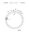
- FIG. 1Adepicts a plan view of a paddock with a tractor towing a field working implement along a closed path.
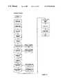
- FIG. 2depicts a block diagram of an agricultural vehicle guidance assist system according to an embodiment of the present invention.
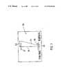
- FIG. 3depicts a screen of a visual display according to an embodiment of the invention.
- FIG. 3Ais a diagram of the position of an agricultural vehicle relative to a wayline.
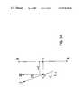
- FIG. 4is a diagram showing the turns that may be made by an agricultural vehicle in moving from one wayline to another.
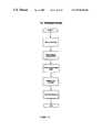
- FIG. 5depicts a block diagram of an agricultural vehicle guidance assist system according to a further embodiment of the present invention.
- FIG. 6is a schematic diagram of a Differential GPS position sensing system as incorporated into an embodiment of the invention.
- FIG. 7depicts the coupling between a member of the steering assembly of an agricultural vehicle and a hall effect device used to monitor steering angle.
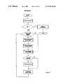
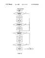
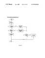
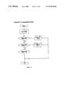
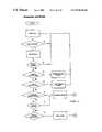
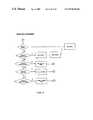
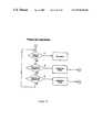
- FIGS. 8-21are flowcharts of a software module for execution by the system of FIG. 2 in one embodiment.
- FIG. 1there is depicted a plan view of a paddock including parallel rows 1 produced by passes of tractor 5 back and forth across the paddock. It is desired that tractor 5 , shown at positions 7 and 9 travels back and forth across the paddock along path 12 . It will be noted that the straight-line segments, or “waylines” 11 A- 11 E of path 12 are all parallel and are offset from each other a distance 13 which is identical to the working width 15 of implement 17 . By offsetting waylines 11 A- 11 E from each other by the working width of the implement, consecutive passes of the implement do not overlap each other nor is there a strip of unprocessed paddock left between adjacent rows.
- FIG. 2there is depicted a schematic representation of the basic elements of a guidance assist system 10 according to an embodiment of the present invention.
- Guidance assist system 10is intended for incorporation into an agricultural vehicle such as tractor 5 .
- Guidance assist system 10includes a central processor 19 which is coupled to a position sensor 23 , visual display 25 , data entry unit 27 and optionally a mechanised steering assist unit 21 .
- a program for execution by processor 19is stored in system memory 14 .
- Position sensor 23provides data to processor 19 at constant intervals.
- the datadynamically specifies the position sensor's, and hence, because guidance assist system 10 is operatively mounted to tractor 5 , the tractor's position as it moves back and forth across the field.
- Visual display 25displays a representation of the tractor's extrapolated path relative to current wayline down which it is desired that the tractor be travelling.
- the representationis frequently updated and may be referred to, by the driver of the tractor, as an aid in reducing deviation of the tractor from the current wayline.
- Data entry unit 27allows an operator to input parameters, such two points defining a first wayline and the working width 15 of implement 17 to processor 19 .
- the system 10may further, or as an alternative to visual display 25 , include a guidance aid in the form of steering assist unit 21 which includes servomotors for mechanically steering the vehicle under control of microprocessor 19 .
- the steering assist unitfurther includes sensors, which transmit data concerning the orientation of the tractor's steering assembly back to processor 19 .
- Central processor 19monitors position data from position sensor 23 and determines discrepancies between the actual path of tractor 5 and the current wayline segment that is intended to be followed. A representation of the difference between the desired path and the actual path is displayed by means of visual display 25 and may be referred to by the operator of the tractor so that the operator may steer the tractor in a direction that reduces the discrepancy. In conjunction with the production of the guidance display, processor 19 also sends commands to actuators of steering assist 21 , which mechanically steer the tractor so as to reduce the discrepancy. Sensors in the steering assist module monitor the angle of the steering wheels of tractor 5 and feed the data back to processor 19 thereby allowing processor 19 to correct for understeering or oversteering.
- tractor 5drives the tractor to a position which will be a first waypoint 29 for defining wayline 11 A.
- the data entry meansis used to inform processor 19 that the waypoint has been reached.
- Processor 19downloads the position of the tractor from position sensor 23 and records this value as waypoint A.
- the vehicleis then driven to a second waypoint 31 and that position is recorded as waypoint B.
- the direction vector pointing from waypoint A to waypoint Bis referred to as a wayline.
- the operatorIn order to enter implement width 15 the operator firstly measures the width, for example with a tape measure, and then inputs the measured value to central processor 19 by means of data entry means 27 .
- the tractoris driven to wherever the operator wishes to commence the first run.
- the data entry meansis then used to inform central processor 19 that the operator desires an indication of the offset of the vehicle's present location from the nearest wayline.
- Processor 19calculates the locations of each of waylines 11 A- 11 E, determining the one closest to the tractor.
- a representation of the relative positions of the closest wayline and of the tractoris generated by means of visual display 25 .
- the operator of the tractorthen drives to a point on the closest wayline and commences travelling down the line. As the driver moves down the line visual display 25 provides a visual guidance screen as shown in FIG. 3 .
- FIG. 3there is depicted a typical image from the guidance screen 33 displayed by visual display 25 .
- a small horizontal line 35having a central gap.
- a similar line 37At the top of screen 33 is a similar line 37 .
- Angled line 41represents the extrapolated direction of travel of tractor 5 .
- the distance 43 between the intersection of line 41 and line 35is proportional to the current offset of tractor 5 from the present wayline as represented by vertical line 39 .
- the distance 45between the end of line 41 and the end of line 39 , is proportional to the offset of tractor 5 from the desired line of travel 39 when the present course of tractor 5 is extrapolated 15 m ahead.
- the driver of tractor 5is able to steer so as to bring line 41 as closely as possible into coincidence with line 39 . If steering assist module 21 is fitted to tractor 5 then the assist module, under command of processor 19 will continually act to bring line 41 into coincidence with line 39 .
- the offset and angular deviation displayed on the screen of FIG. 3is calculated as follows.
- wayline ABhas associated with it a direction vector AB.
- the direction vector of tractor 5is E and is calculated by tracking the position of the tractor over past time periods.
- points A and Bare either the original waypoints entered by the operator of the guidance system, or are new waypoints generated by the system from the offset data, then in either case their coordinates are known. Consequently vector AB is readily calculated as is ⁇ .
- the distance ad from the present position, C t0 of tractor 5 , to C m the closest point on wayline ABmay be calculated using straightforward vector mathematics.
- tractor 5moves along wayline 47 in a direction from waypoint A to waypoint B.
- the turn datais entered by means of data entry unit 27 .
- microprocessor 19calculates the position of the next wayline to be followed and the direction that the tractor is to move along the wayline. For example, if the operator enters a turn left command as indicated by arc 49 then microprocessor 19 will set the current wayline to wayline 51 and will compare the positional data from position sensor 23 with wayline 51 . Corresponding steering commands will be sent to steering assist unit 21 in the event that it is fitted.
- microprocessor 19will set line 39 of display 33 to track wayline 55 and will compare the positional data from position sensor 23 with a desired line segment corresponding to line 51 . It may be that the operator wishes to pass back over the wayline which has just been followed, for example wayline 56 . In that event the operator enters a “vehicle reverse” command as indicated by circle 54 . In response microprocessor 19 changes the sign of the direction vector associated with wayline 56 .
- FIG. 1Athere is depicted a plan view of a field in which tractor 5 follows a “wayline” formed by connecting a very large number of waypoints.
- the waylinesare closed polygons defined by up to 1000 waypoints per kilometre. If this arrangement is used to guide tractor 5 then system 10 calculates a set of concentric waylines offset from each other by the working implement width entered by the operator of the system. This is done by connecting adjacent waypoints 42 A, . . . , 42 n with direction vectors 44 A, . . . , 44 n .
- the normal 46 A, . . . , 46 n to each direction vectoris then calculated and the points 48 A, . . .
- the operator of vehicle 5indicates same to system 10 by means of data entry module 27 .
- Microprocessor 19is programmed to indicate, by means of visual display 25 the offset from the next inner (or outer) waypolygon. The driver then guides the vehicle, with the aid of steering assist module 21 if fitted, to the adjacent waypolygon and proceeds about it until the complete at which point the procedure is repeated in respect of the next concentrically located waypolygon.
- FIG. 5there is provided a processing means in the form of an IBM compatible microprocessor board 61 .
- Processor board 61is coupled to a LCD touch screen 63 which allows operator data entry and display of information such as that of the guidance screen shown in FIG. 3 .
- Processor board 69further receives data from geographical positioning system (GPS) receiver 81 , and radio modem 79 . As will be explained shortly, data from radio modem 79 is used to correct data output by GPS receiver 81 .
- GPSgeographical positioning system
- Processor 61further receives data from accelerometers 67 , wheel angle sensors 65 and gyroscope 71 , all of which Is converted to a suitable digital format by data acquisition module 69 .
- Pulse width modulated control signals from processor board 61are transmitted to opto coupler board 75 which electrically isolates the microprocessor from the solenoids and converts the control signals into current signals suitable for solenoid operation.
- Solenoids 77together with wheel angle sensors 65 , form the steering assist module 21 of FIG. 2 .
- System memory 73stores a program which is operatively executed by microprocessor board 61 in order to effect the functioning of the overall system as previously described.
- GPS receiver 81is a commercially available unit being the Novotel Millenium Propack RT 2 manufactured by Novotel Corp of Calgary Canada. Receiver 81 generates positional data on the basis of signals emanating from a network of twenty-seven satellites.
- the GPS systemprovides two separate transmissions; an extremely high accuracy military transmission, and a slightly degraded civilian transmission.
- the civilian transmissioncontains errors, which are intentionally introduced in order to lower the accuracy of the position data accessible to non-military personnel.
- DGPSDifferential GPS
- a variationis Wide Angle Differential GPS
- radio modem 79is provided for receiving correction data from a base station.
- the base stationprocesses data from a fixed receiver, of known location, and generates correctional data which computer 61 uses to adjust data from mobile GPS receiver 81 .
- FIG. 6a differential GPS system is depicted.
- an agricultural vehiclebeing tractor 5 tows an implement 17 .
- Tractor 5is fitted with the guidance system of FIG. 5 , including radio modem 79 , which is connected to UHF antenna 83 .
- GPS receiver 81is connected to satellite antenna 85 , which is mounted on the roof of tractor 5 .
- Base station 87includes a satellite antenna which is connected to GPS receiver 91 and receives signals from orbiting GPS satelites 99 , 101 , 103 .
- Receiver 91on the basis of the signals coming from antenna 89 calculates and provides positional data to computer 93 .
- the computercompares the positional data from receiver 91 with a predetermined and accurately known position for antenna 89 .
- Radio modem 95On the basis of the comparison computer 93 is able to calculate an error factor, which is continuously updated and passed to radio modem 95 .
- Radio modem 95generates a serial data signal which is upconverted to the UHF band and propagated by base antenna 97 .
- the transmitted error signalis received by the UHF antenna 83 mounted on tractor 5 .
- radio modem 79converts the received error factor signal into a digital format suitable for processing by microprocessor board 61 .
- the microprocessorrunning a suitable program, is able to adjust the data from GPS receiver 81 in order to drastically increase the accuracy of the positional data obtained.
- Accelerometers 67are further used to increase the accuracy of the steering guidance system shown in FIG. 5 .
- the accelerometersmeasure acceleration in three dimensions. Due to the limitations of current GPS technology, positional updates are only available once every 200 ms. During the time between updates positional values may vary significantly, negatively influencing the accuracy of the overall system during the intervening time. Data from accelerometers 67 is generated 150 times per second and is used by microprocessor 61 to calculate the relative change in position at a number of time points during the time between GPS updates. Consequently the incorporation of the accelerometers increases the accuracy of the positional data available when calculating the deviation of tractor 5 from the desired path. By making use of the accelerometers 67 in conjunction with the DGPS data the position of vehicle 5 may be determined to better than 2 cm accuracy at any given time.
- the vehicle positioning apparatus of the preferred embodimentincludes a steering control system based around a proportional-integral-differential (PID) controller which is modeled and effected in software stored in memory 73 .
- PIDproportional-integral-differential
- the output of the PID controlleris used to set a solenoid control variable which then determines the length and quantity of a series of pulses output to solenoids 77 in order to control the tractor's steering mechanism.
- Several external sensorsare used to further refine the steering control system function being wheel angle sensors 65 and tilt sensing by means of gyroscope 71 .
- wheel angle sensors 65are used in the vehicle positioning apparatus of the preferred embodiment in order to determine the degree of steering of the tractor's steered wheels.
- the sensorsare preferably based on the Hall effect and can accurately track small changes in magnetic flux density.
- the unitsare comprised of three major components, namely a sensor 105 , a magnet 107 and mounting arm or mechanical linkage 109 , which is mechanically coupled to steering arm 111 of the steering assembly of tractor 5 .
- sensor 105rotates, by virtue of mechanical coupling to arm 111 within magnet 107 , which is held stationary relative to arm 111 . Relative motion of the sensor within magnet 107 causes a magnetic flux change. This change in flux is represented by a linear output relationship between the wheel angle and the signal voltage.
- the wheel angle sensorsare supplied with a five volt (5V) and a ground (GND) supply.
- the input signal returned to the hardware moduleis proportional to the angle of rotation of the wheel and is of course limited to the supply voltage.
- the vehicle positioning apparatus of the preferred embodimentalso makes use of a gyroscope to measure tilt of the vehicle thereby further increasing the accuracy of the steering control system.
- the pitch (relative height of the front of the vehicle with respect to its rear) and roll (relative height of the leftmost side of the vehicle with respect to its rightmost side) of the vehicle to which it is attachedare measured using both accelerometer 67 and gyroscope 71 .
- the accelerometeris sensitive to forces lateral to the direction of motion whereas the rate gyroscope is sensitive to rate of rotation about the roll axis.
- the accelerometeris adapted to accurately measure the steady state tilt but is unsuited to tracking dynamic changes in tilt.
- the rate gyroscopeis well suited to tracking dynamic changes though it does not provide information regarding the steady state value of the tilt.
- the microprocessoris able to generate data which accurately tracks roll with good dynamic response.
- the software moduletogether with the hardware module form the complete GPS information interpretation and processing system used in the apparatus of the present invention.
- the software module functionalityfacilitates not only the precision guidance of the agricultural vehicle, but also the logging of data received from the GPS receiver and internally calculated data. This data may be transmitted back to the base station 87 for future receipt and use in field contour mapping and for driver and agricultural vehicle performance reports.
- the software moduleincludes a main routine as depicted in FIG. 8 . External to this main routine are system interrupts which indicate the receipt of new GPS data or facilitate the execution of time dependent events.
- the system interrupt routinesare depicted in FIGS. 14 and 15 .
- the user interface for the software moduleis divided into a series of screens, each relevant to a particular feature or configuration item of the vehicle position apparatus.
- a process user input routineis displayed in FIGS. 16 to 20 to depict the flow of control between the software module screens.
- a user interface main screenprovides a number of pieces of textual information to the agricultural vehicle operator, as well as a graphical representation of the current position and heading.
- the textual informationis displayed as a header with an associated value.
- the headers and their relevance to the operation of the vehicle position apparatus of the preferred embodimentare as follows:
- the vehicle position apparatus of the preferred embodimentcontains a diagnostics function which allows operators to ensure that the system is functioning correctly.
- the diagnostics featuresare as follows:
- the mobile unit software module for the vehicle positioning apparatus of the preferred embodimentprovides safety mechanisms for the agricultural vehicle operator.
- the inherent safety of the vehicle positioning apparatus of the preferred embodimentis assured through routines in the software module specifically dedicated to verify correct operation of the system, and to provide mechanisms to inhibit the actions of out of range inputs and outputs.
- the safety features present in the vehicle positioning apparatus of the preferred embodimentmay include the following:
Landscapes
- Engineering & Computer Science (AREA)
- Radar, Positioning & Navigation (AREA)
- Remote Sensing (AREA)
- Life Sciences & Earth Sciences (AREA)
- Soil Sciences (AREA)
- Environmental Sciences (AREA)
- Mechanical Engineering (AREA)
- Aviation & Aerospace Engineering (AREA)
- Physics & Mathematics (AREA)
- General Physics & Mathematics (AREA)
- Automation & Control Theory (AREA)
- Guiding Agricultural Machines (AREA)
- Steering Control In Accordance With Driving Conditions (AREA)
Abstract
Description
- a) position determining means arranged to generate vehicle position data;
- b) data entry means facilitating entry of an initial path by an operator and a desired offset distance between paths;
- c) processing means coupled to said position determining means and operatively arranged to generate said paths based on said initial path, said processing means generating a guidance signal indicative of errors in the position of the vehicle relative to one of said paths;
- d) guidance means coupled to said microprocessor and arranged to aid in guiding said vehicle thereby reducing said errors.
- WWHDG-Waypoint Heading is the angle between a line connecting waypoints one and two, and a line connecting waypoint one and true north. This value is useful for navigation purposes.
- HDG-Headin is the current heading with respect to true north. this value is useful for navigation purposes.
- SLOP-Slop is the current positional uncertainty. the value is in centimeters and reflects the error inherent in the positional value used for navigational calculations.
- XTRK-Crosstrack error is the distance from the desired line of travel to the current line of travel. This value is presented in meters.
- SATS-This value corresponds to the number of satellites currently in view by the GPS receiver. The vehicle positioning apparatus of the preferred embodiment requires at least four common satellites in view at all times.
- CPU-The CPU parameter represents the current loading on the processor board.
- CPU-Represents current loading on the GPS receiver.
- Number of Satellites in View at Mobile Unit-as described in SATS above.
- CPU Load on GPS Receiver Card-as described in % CPU above.
- CPU Load on Local Processor-as described in CPU above.
- Number of Satellites in View at Base Unit-This value corresponds to the number of satellites currently in view by the GPS receiver located at the base station. The vehicle positioning apparatus of the preferred embodiment requires at least four common satellites in view at all times.
- Rolling Time Update from the GPS Receiver-This constantly changing time value confirms communication with the GPS satellites.
- Solenoid Response Test-This test may be performed to ensure the correct operation of the solenoids.
- Analogue Input Range Tests-Performed routinely on the applied analogue inputs to alert operators to external device faults.
- Radio Communication Continuity Test-Alerts operators to radio device faults.
- Anomaly: Vehicle position incorrect by a distance of 1 m or more.
- Action: Steering Control Outputs disabled.
- Effect: Allows agricultural vehicle driver intervention in the case of an emergency.
- Anomaly: Wheel angle sensors returning out of range value.
- Action: Steering control outputs disabled
- Effect: Allows agricultural vehicle driver intervention in the case of an emergency.
- Anomaly: Vehicle heading incorrect by an angle of thirty degrees or more.
- Action: Steering Control outputs disabled.
- Effect: Allows agricultural vehicle driver intervention in the case of an emergency.
- Anomaly: Hardware Module unable to set wheel angle to the desired value within four seconds (4sec)
- Action: Steering control outputs disabled.
- Effect: Allows agricultural vehicle driver intervention in case of an emergency.
- Anomaly: Postion uncertainty greater than 50 cm
- Action: Steering Control outputs disabled
- Effect: Allows agricultural vehicle driver intervention in the case of satellite or receiver down time, or radio data communication lapse.
- Anomaly: Velocity of agricultural vehicle less than 0.5 m/s
- Action: Steering Control outputs disabled.
- Effect: Allows agricultural vehicle to perform necessarily low velocity maneuvers without interruption.
- Anomaly: Velocity of agricultural vehicle greater than 5 m/s
- Action: Steering Control outputs disabled.
- Effect: Allows agricultural vehicle to perform necessarily high velocity maneuvers without interruption.
It will be appreciated by those skilled in theart that the above has been given only by way of illustrative example of the invention and that all such modifications and variations thereto as would be apparent to persons skilled in the art are deemed to fall within the broad scope and ambit of the invention as is herein defined in the appended claims.
Claims (8)
Applications Claiming Priority (2)
| Application Number | Priority Date | Filing Date | Title |
|---|---|---|---|
| AUPP6795AAUPP679598A0 (en) | 1998-10-27 | 1998-10-27 | A vehicle navigation apparatus |
| PCT/AU1999/000930WO2000024239A1 (en) | 1998-10-27 | 1999-10-27 | Vehicle positioning apparatus and method |
Publications (1)
| Publication Number | Publication Date |
|---|---|
| US6876920B1true US6876920B1 (en) | 2005-04-05 |
Family
ID=3811011
Family Applications (1)
| Application Number | Title | Priority Date | Filing Date |
|---|---|---|---|
| US09/830,479Expired - LifetimeUS6876920B1 (en) | 1998-10-27 | 1999-10-27 | Vehicle positioning apparatus and method |
Country Status (3)
| Country | Link |
|---|---|
| US (1) | US6876920B1 (en) |
| AU (1) | AUPP679598A0 (en) |
| WO (1) | WO2000024239A1 (en) |
Cited By (75)
| Publication number | Priority date | Publication date | Assignee | Title |
|---|---|---|---|---|
| US20050171693A1 (en)* | 2003-12-12 | 2005-08-04 | Arthur Lange | GPS receiver with autopilot and integrated lightbar display |
| US20050197757A1 (en)* | 2003-03-31 | 2005-09-08 | Flann Nicholas S. | Path planner and method for planning a path plan having a spiral component |
| US20050284119A1 (en)* | 2004-06-28 | 2005-12-29 | Andreas Brunnert | Method and device for controlling an agricultural working machine |
| US20060116798A1 (en)* | 2004-11-30 | 2006-06-01 | Mark Gibson | Method and system for implementing automatic vehicle control with parameter-driven disengagement |
| US20060142940A1 (en)* | 2004-12-27 | 2006-06-29 | Lg Electronics Inc. | Method for determining deviation of a mobile object in a navigation system from a travel route |
| US20060178823A1 (en)* | 2005-02-04 | 2006-08-10 | Novariant, Inc. | System and method for propagating agricultural vehicle guidance paths that have varying curvature along their length |
| US20060178825A1 (en)* | 2005-02-04 | 2006-08-10 | Novariant, Inc. | System and method for interactive selection of agricultural vehicle guide paths with varying curvature along their length |
| US20060178820A1 (en)* | 2005-02-04 | 2006-08-10 | Novariant, Inc. | System and method for guiding an agricultural vehicle through a recorded template of guide paths |
| US20060282205A1 (en)* | 2005-06-09 | 2006-12-14 | Lange Arthur F | System for guiding a farm implement between swaths |
| US20070076202A1 (en)* | 2005-09-30 | 2007-04-05 | Institut National D'optique | Real-time measuring of the spatial distribution of sprayed aerosol particles |
| US20070112478A1 (en)* | 2005-10-07 | 2007-05-17 | Saab Ab | Method and system for generating a route |
| US20070233338A1 (en)* | 2006-03-30 | 2007-10-04 | Honeywell International Inc. | Real time planning and scheduling for a team of unmanned vehicles |
| US20080086249A1 (en)* | 2006-10-05 | 2008-04-10 | Trimble Navigation Limited | Farm apparatus having implement sidehill drift compensation |
| EP1865396A3 (en)* | 2006-06-06 | 2008-05-28 | CLAAS Selbstfahrende Erntemaschinen GmbH | Method and device for displaying vehicle movements |
| US20080249692A1 (en)* | 2007-04-03 | 2008-10-09 | Dix Peter J | Method for creating end of row turns for agricultural vehicles |
| US20090037041A1 (en)* | 2007-07-31 | 2009-02-05 | Aaron Matthew Senneff | Method and system for generating end turns |
| US20090118904A1 (en)* | 2006-02-27 | 2009-05-07 | Denis Allan Birnie | Method and system for planning the path of an agricultural vehicle |
| US20100185366A1 (en)* | 2005-07-19 | 2010-07-22 | Heiniger Richard W | Adaptive machine control system and method |
| JP2012240504A (en)* | 2011-05-18 | 2012-12-10 | Mitsubishi Agricultural Machinery Co Ltd | Working vehicle |
| WO2013083311A1 (en)* | 2011-12-09 | 2013-06-13 | Robert Bosch Gmbh | Method and control device for guiding an agricultural machine |
| US20130184944A1 (en)* | 2010-07-14 | 2013-07-18 | Bart M.A. Missotten | Method and device for predictive control of agricultural vehicle systems |
| US20130289837A1 (en)* | 2012-04-25 | 2013-10-31 | Geotab Inc. | Reversing vehicle remote telematics detection |
| US8606454B2 (en) | 2011-02-18 | 2013-12-10 | Cnh America Llc | System and method for synchronized control of a harvester and transport vehicle |
| US20140222172A1 (en)* | 2012-02-08 | 2014-08-07 | Adam Hudson | Control Apparatus for Automating the Operation of Machinery |
| US20140324292A1 (en)* | 2013-04-26 | 2014-10-30 | Furuno Electric Company Limited | Information display device and course setting method |
| US20150285647A1 (en)* | 2014-04-02 | 2015-10-08 | Claas E-Systems Kgaa Mbh & Co Kg | Planning system and method for planning fieldwork |
| US20160004252A1 (en)* | 2013-02-15 | 2016-01-07 | Murata Machinery, Ltd. | Delivery vehicle and method and program for controlling drive of delivery vehicle |
| US9380741B2 (en) | 2011-12-28 | 2016-07-05 | Husqvarna Ab | Yard maintenance vehicle route and orientation mapping system |
| AU2015268642B2 (en)* | 2014-12-10 | 2017-05-11 | Iseki & Co., Ltd. | Agricultural working vehicle |
| US9671244B2 (en) | 2015-09-18 | 2017-06-06 | Les Solutions Cyclelabs Inc. | Electronic device and method for providing travel information |
| US9733643B2 (en) | 2013-12-20 | 2017-08-15 | Agjunction Llc | Hydraulic interrupter safety system and method |
| US9781915B2 (en) | 2013-03-14 | 2017-10-10 | Agjunction Llc | Implement and boom height control system and method |
| US9795074B2 (en)* | 2015-10-27 | 2017-10-24 | Cnh Industrial America Llc | Automatic swath generation device and methods |
| US9857478B2 (en) | 2015-01-27 | 2018-01-02 | Agjunction Llc | Apparatus and method to mount steering actuator |
| US9880562B2 (en) | 2003-03-20 | 2018-01-30 | Agjunction Llc | GNSS and optical guidance and machine control |
| US20180050724A1 (en)* | 2011-09-07 | 2018-02-22 | Cnh Industrial America Llc | Steerable vehicle |
| US9903953B2 (en) | 2010-11-19 | 2018-02-27 | Agjunction Llc | Portable base station network for local differential GNSS corrections |
| US9945957B2 (en) | 2013-03-14 | 2018-04-17 | Agjunction Llc | Machine control system and method |
| EP3316065A1 (en)* | 2016-10-26 | 2018-05-02 | Einhell Germany AG | Method for determining a path |
| WO2018080969A1 (en)* | 2016-10-24 | 2018-05-03 | Agco International Gmbh | Land mapping and guidance system |
| USRE47055E1 (en) | 2009-01-17 | 2018-09-25 | Agjunction Llc | Raster-based contour swathing for guidance and variable-rate chemical application |
| US10104827B2 (en) | 2015-07-08 | 2018-10-23 | The Royal Institution For The Advancement Of Learning/Mcgill University | Guidance system and steering control device for an agricultural vehicle |
| USRE47101E1 (en) | 2003-03-20 | 2018-10-30 | Agjunction Llc | Control for dispensing material from vehicle |
| US10131376B2 (en) | 2013-01-30 | 2018-11-20 | Agjunction Llc | Steering controller for precision farming |
| US10180328B2 (en)* | 2013-07-10 | 2019-01-15 | Agco Coporation | Automating distribution of work in a field |
| US10209714B2 (en) | 2016-04-12 | 2019-02-19 | Agjunction Llc | Line acquisition path generation |
| US10241215B2 (en) | 2015-11-19 | 2019-03-26 | Agjunction Llc | Sensor alignment calibration |
| US10239555B2 (en) | 2015-11-19 | 2019-03-26 | Agjunction Llc | Single-mode implement steering |
| US10266201B2 (en) | 2015-11-19 | 2019-04-23 | Agjunction Llc | K-turn path controller |
| WO2019096262A1 (en)* | 2017-11-16 | 2019-05-23 | 南京德朔实业有限公司 | Intelligent lawn mowing system |
| CN110044363A (en)* | 2018-01-15 | 2019-07-23 | 上海谷米实业有限公司 | A kind of automobile with positioning device |
| US10407096B2 (en)* | 2014-10-07 | 2019-09-10 | Jtekt Europe | Securing of a driving assistance function within a power steering |
| USRE47648E1 (en) | 2009-09-17 | 2019-10-15 | Agjunction Llc | Integrated multi-sensor control system and method |
| USD863367S1 (en) | 2015-07-08 | 2019-10-15 | The Royal Institution For The Advancement Of Learning/Mcgill University | Steering wheel adapter for agricultural vehicle vision guidance system |
| EP3441791A4 (en)* | 2016-04-06 | 2020-03-04 | Kubota Corporation | POSITIONING DETECTOR AND WORKING MACHINE WITH POSITIONING DETECTOR |
| USRE48154E1 (en) | 2012-07-17 | 2020-08-11 | Agjunction Llc | System and method for integrating automatic electrical steering with GNSS guidance |
| US10822017B2 (en) | 2016-10-17 | 2020-11-03 | Agjunction Llc | Integrated auto-steer system for vehicle |
| US10845375B2 (en) | 2016-02-19 | 2020-11-24 | Agjunction Llc | Thermal stabilization of inertial measurement units |
| US10866109B2 (en) | 2017-10-31 | 2020-12-15 | Agjunction Llc | Three-dimensional terrain mapping |
| US10890922B2 (en) | 2015-11-19 | 2021-01-12 | Agjunction Llc | Automated multi-vehicle alignment steering |
| USRE48527E1 (en) | 2007-01-05 | 2021-04-20 | Agjunction Llc | Optical tracking vehicle control system and method |
| US20210114659A1 (en)* | 2018-06-25 | 2021-04-22 | Kubota Corporation | Working vehicle |
| US10986767B2 (en) | 2018-09-14 | 2021-04-27 | Agjunction Llc | Using smart-phones and other hand-held mobile devices in precision agriculture |
| USD921506S1 (en) | 2019-04-26 | 2021-06-08 | SmartHalo Technologies Inc. | Electronic device for providing travel information |
| US11091192B2 (en) | 2019-07-31 | 2021-08-17 | Agjunction Llc | Integrated vehicle guidance and steering system |
| US11096323B2 (en)* | 2017-04-18 | 2021-08-24 | CropZilla Software, Inc. | Machine control system providing actionable management information and insight using agricultural telematics |
| US11132003B2 (en) | 2018-09-14 | 2021-09-28 | Agjunction Llc | Integrated GNSS and steering for agricultural guidance systems |
| US11167743B2 (en) | 2018-04-03 | 2021-11-09 | AgJunction, LLC | Automatic pitch mounting compensation in an automatic steering system |
| US11180189B2 (en)* | 2015-11-19 | 2021-11-23 | Agjunction Llc | Automated reverse implement parking |
| US11229154B2 (en)* | 2018-09-04 | 2022-01-25 | Deere & Company | Automatic path correction for guided vehicles |
| US11269346B2 (en) | 2017-06-22 | 2022-03-08 | Agjunction Llc | 3-d image system for vehicle control |
| US20220104422A1 (en)* | 2019-09-06 | 2022-04-07 | Kubota Corporation | Working vehicle |
| US20220107649A1 (en)* | 2019-09-26 | 2022-04-07 | Kubota Corporation | Working vehicle |
| CN114375676A (en)* | 2020-10-16 | 2022-04-22 | 南京德朔实业有限公司 | Self-moving equipment, control method thereof and self-moving working system |
| US11399454B2 (en)* | 2018-01-23 | 2022-08-02 | Kubota Corporation | Working vehicle |
Families Citing this family (9)
| Publication number | Priority date | Publication date | Assignee | Title |
|---|---|---|---|---|
| AUPR430301A0 (en) | 2001-04-09 | 2001-05-17 | Agsystems Pty Ltd | Soil-cultivation implement control apparatus and method |
| AU2002244539B2 (en)* | 2001-04-09 | 2007-08-23 | Agjunction Llc | Soil cultivation implement control apparatus and method |
| AUPR733701A0 (en)* | 2001-08-29 | 2001-09-20 | Beeline Technologies | Apparatus and method for assisted navigation of a land vehicle |
| US7162348B2 (en) | 2002-12-11 | 2007-01-09 | Hemisphere Gps Llc | Articulated equipment position control system and method |
| US7437230B2 (en) | 2003-03-20 | 2008-10-14 | Hemisphere Gps Llc | Satellite based vehicle guidance control in straight and contour modes |
| US7593798B2 (en) | 2003-10-30 | 2009-09-22 | Deere & Company | Vehicular guidance system having compensation for variations in ground elevation |
| US7388539B2 (en) | 2005-10-19 | 2008-06-17 | Hemisphere Gps Inc. | Carrier track loop for GNSS derived attitude |
| US8565978B2 (en)* | 2010-10-29 | 2013-10-22 | Cnh America Llc | Steering wheel motion and self-cancelling turn signal sensor |
| CZ309457B6 (en)* | 2017-06-02 | 2023-02-01 | Farmet A.S. | An agricultural machine for tilling and/or sowing and setting it up |
Citations (17)
| Publication number | Priority date | Publication date | Assignee | Title |
|---|---|---|---|---|
| US4398195A (en)* | 1979-07-02 | 1983-08-09 | Del Norte Technology, Inc. | Method of and apparatus for guiding agricultural aircraft |
| US4558760A (en)* | 1982-01-22 | 1985-12-17 | Preciculture | Apparatus for automatically guiding the movement of a vehicle, especially an off-road vehicle |
| US4706773A (en)* | 1981-07-01 | 1987-11-17 | Imperial Chemical Industries Plc | Vehicle guidance system particularly for use in agriculture |
| US4939663A (en)* | 1988-04-04 | 1990-07-03 | Harris Corporation | Elevation map-referenced mechanism for updating vehicle navigation system estimates |
| US4967362A (en)* | 1989-01-30 | 1990-10-30 | Eaton Corporation | Automatic steering apparatus for crop vehicle |
| US5019990A (en)* | 1989-01-07 | 1991-05-28 | Honda Giken Kogyo Kabushiki Kaisha | Position detector for moving vehicle |
| US5334987A (en)* | 1993-04-01 | 1994-08-02 | Spectra-Physics Laserplane, Inc. | Agricultural aircraft control system using the global positioning system |
| US5375059A (en)* | 1990-02-05 | 1994-12-20 | Caterpillar Inc. | Vehicle position determination system and method |
| WO1998046065A1 (en) | 1997-04-16 | 1998-10-22 | Carnegie Mellon University | Agricultural harvester with robotic control |
| US5928309A (en)* | 1996-02-05 | 1999-07-27 | Korver; Kelvin | Navigation/guidance system for a land-based vehicle |
| US5955973A (en)* | 1993-12-30 | 1999-09-21 | Concord, Inc. | Field navigation system |
| US5987383A (en)* | 1997-04-28 | 1999-11-16 | Trimble Navigation | Form line following guidance system |
| US5991694A (en)* | 1995-11-13 | 1999-11-23 | Caterpillar Inc. | Method and apparatus for determining the location of seedlings during agricultural production |
| US6087984A (en)* | 1998-05-04 | 2000-07-11 | Trimble Navigation Limited | GPS guidance system for use with circular cultivated agricultural fields |
| US6199000B1 (en)* | 1998-07-15 | 2001-03-06 | Trimble Navigation Limited | Methods and apparatus for precision agriculture operations utilizing real time kinematic global positioning system systems |
| US6314348B1 (en)* | 1998-02-11 | 2001-11-06 | Trimble Navigation Limited | Correction control for guidance control system |
| US6400143B1 (en)* | 1997-09-26 | 2002-06-04 | The Torrington Company | Digital sensor of relative position |
- 1998
- 1998-10-27AUAUPP6795Apatent/AUPP679598A0/ennot_activeAbandoned
- 1999
- 1999-10-27USUS09/830,479patent/US6876920B1/ennot_activeExpired - Lifetime
- 1999-10-27WOPCT/AU1999/000930patent/WO2000024239A1/enactiveApplication Filing
Patent Citations (18)
| Publication number | Priority date | Publication date | Assignee | Title |
|---|---|---|---|---|
| US4398195A (en)* | 1979-07-02 | 1983-08-09 | Del Norte Technology, Inc. | Method of and apparatus for guiding agricultural aircraft |
| US4706773A (en)* | 1981-07-01 | 1987-11-17 | Imperial Chemical Industries Plc | Vehicle guidance system particularly for use in agriculture |
| US4558760A (en)* | 1982-01-22 | 1985-12-17 | Preciculture | Apparatus for automatically guiding the movement of a vehicle, especially an off-road vehicle |
| US4939663A (en)* | 1988-04-04 | 1990-07-03 | Harris Corporation | Elevation map-referenced mechanism for updating vehicle navigation system estimates |
| US5019990A (en)* | 1989-01-07 | 1991-05-28 | Honda Giken Kogyo Kabushiki Kaisha | Position detector for moving vehicle |
| US4967362A (en)* | 1989-01-30 | 1990-10-30 | Eaton Corporation | Automatic steering apparatus for crop vehicle |
| US5375059A (en)* | 1990-02-05 | 1994-12-20 | Caterpillar Inc. | Vehicle position determination system and method |
| US5334987A (en)* | 1993-04-01 | 1994-08-02 | Spectra-Physics Laserplane, Inc. | Agricultural aircraft control system using the global positioning system |
| US5955973A (en)* | 1993-12-30 | 1999-09-21 | Concord, Inc. | Field navigation system |
| US5991694A (en)* | 1995-11-13 | 1999-11-23 | Caterpillar Inc. | Method and apparatus for determining the location of seedlings during agricultural production |
| US5928309A (en)* | 1996-02-05 | 1999-07-27 | Korver; Kelvin | Navigation/guidance system for a land-based vehicle |
| WO1998046065A1 (en) | 1997-04-16 | 1998-10-22 | Carnegie Mellon University | Agricultural harvester with robotic control |
| US5987383A (en)* | 1997-04-28 | 1999-11-16 | Trimble Navigation | Form line following guidance system |
| US5987383C1 (en)* | 1997-04-28 | 2006-06-13 | Trimble Navigation Ltd | Form line following guidance system |
| US6400143B1 (en)* | 1997-09-26 | 2002-06-04 | The Torrington Company | Digital sensor of relative position |
| US6314348B1 (en)* | 1998-02-11 | 2001-11-06 | Trimble Navigation Limited | Correction control for guidance control system |
| US6087984A (en)* | 1998-05-04 | 2000-07-11 | Trimble Navigation Limited | GPS guidance system for use with circular cultivated agricultural fields |
| US6199000B1 (en)* | 1998-07-15 | 2001-03-06 | Trimble Navigation Limited | Methods and apparatus for precision agriculture operations utilizing real time kinematic global positioning system systems |
Cited By (122)
| Publication number | Priority date | Publication date | Assignee | Title |
|---|---|---|---|---|
| US9880562B2 (en) | 2003-03-20 | 2018-01-30 | Agjunction Llc | GNSS and optical guidance and machine control |
| US10168714B2 (en) | 2003-03-20 | 2019-01-01 | Agjunction Llc | GNSS and optical guidance and machine control |
| USRE47101E1 (en) | 2003-03-20 | 2018-10-30 | Agjunction Llc | Control for dispensing material from vehicle |
| US9886038B2 (en) | 2003-03-20 | 2018-02-06 | Agjunction Llc | GNSS and optical guidance and machine control |
| US20050197757A1 (en)* | 2003-03-31 | 2005-09-08 | Flann Nicholas S. | Path planner and method for planning a path plan having a spiral component |
| US7228214B2 (en)* | 2003-03-31 | 2007-06-05 | Deere & Company | Path planner and method for planning a path plan having a spiral component |
| US7200490B2 (en)* | 2003-12-12 | 2007-04-03 | Trimble Navigation Limited | GPS receiver with autopilot and integrated lightbar display |
| US20050171693A1 (en)* | 2003-12-12 | 2005-08-04 | Arthur Lange | GPS receiver with autopilot and integrated lightbar display |
| US20050284119A1 (en)* | 2004-06-28 | 2005-12-29 | Andreas Brunnert | Method and device for controlling an agricultural working machine |
| US7574290B2 (en) | 2004-11-30 | 2009-08-11 | Trimble Navigation Limited | Method and system for implementing automatic vehicle control with parameter-driven disengagement |
| US20060116798A1 (en)* | 2004-11-30 | 2006-06-01 | Mark Gibson | Method and system for implementing automatic vehicle control with parameter-driven disengagement |
| US20060195238A1 (en)* | 2004-11-30 | 2006-08-31 | Mark Gibson | Method and system for preventing automatic re-engagement of automatic vehicle control |
| US20060142940A1 (en)* | 2004-12-27 | 2006-06-29 | Lg Electronics Inc. | Method for determining deviation of a mobile object in a navigation system from a travel route |
| US20060178820A1 (en)* | 2005-02-04 | 2006-08-10 | Novariant, Inc. | System and method for guiding an agricultural vehicle through a recorded template of guide paths |
| US20060178825A1 (en)* | 2005-02-04 | 2006-08-10 | Novariant, Inc. | System and method for interactive selection of agricultural vehicle guide paths with varying curvature along their length |
| US20060178823A1 (en)* | 2005-02-04 | 2006-08-10 | Novariant, Inc. | System and method for propagating agricultural vehicle guidance paths that have varying curvature along their length |
| US7451030B2 (en) | 2005-02-04 | 2008-11-11 | Novariant, Inc. | System and method for interactive selection and determination of agricultural vehicle guide paths offset from each other with varying curvature along their length |
| US20060282205A1 (en)* | 2005-06-09 | 2006-12-14 | Lange Arthur F | System for guiding a farm implement between swaths |
| US8359141B1 (en)* | 2005-06-09 | 2013-01-22 | Trimble Navigation Limited | Calibrated farming system |
| US7860628B2 (en)* | 2005-06-09 | 2010-12-28 | Trimble Navigation Limited | System for guiding a farm implement between swaths |
| US8214111B2 (en)* | 2005-07-19 | 2012-07-03 | Hemisphere Gps Llc | Adaptive machine control system and method |
| US20100185366A1 (en)* | 2005-07-19 | 2010-07-22 | Heiniger Richard W | Adaptive machine control system and method |
| US20070076202A1 (en)* | 2005-09-30 | 2007-04-05 | Institut National D'optique | Real-time measuring of the spatial distribution of sprayed aerosol particles |
| US7388662B2 (en)* | 2005-09-30 | 2008-06-17 | Institut National D'optique | Real-time measuring of the spatial distribution of sprayed aerosol particles |
| US9097527B2 (en)* | 2005-10-07 | 2015-08-04 | Saab Ab | Method and system for generating a route |
| US20070112478A1 (en)* | 2005-10-07 | 2007-05-17 | Saab Ab | Method and system for generating a route |
| US10378896B2 (en)* | 2006-02-27 | 2019-08-13 | Trimble Inc. | Method and system for planning the path of an agricultural vehicle |
| US20090118904A1 (en)* | 2006-02-27 | 2009-05-07 | Denis Allan Birnie | Method and system for planning the path of an agricultural vehicle |
| US20070233338A1 (en)* | 2006-03-30 | 2007-10-04 | Honeywell International Inc. | Real time planning and scheduling for a team of unmanned vehicles |
| US7603212B2 (en)* | 2006-03-30 | 2009-10-13 | Honeywell International, Inc. | Real time planning and scheduling for a team of unmanned vehicles |
| RU2467374C2 (en)* | 2006-06-06 | 2012-11-20 | КЛААС Зельбстфаренде Эрнтемашинен ГмбХ | Device to determine vehicle's route |
| EP1865396A3 (en)* | 2006-06-06 | 2008-05-28 | CLAAS Selbstfahrende Erntemaschinen GmbH | Method and device for displaying vehicle movements |
| US7844378B2 (en) | 2006-10-05 | 2010-11-30 | Trimble Navigation Limited | Farm apparatus having implement sidehill drift compensation |
| US8489290B1 (en)* | 2006-10-05 | 2013-07-16 | Trimble Navigation Limited | Farm sidehill compensation |
| US20080086249A1 (en)* | 2006-10-05 | 2008-04-10 | Trimble Navigation Limited | Farm apparatus having implement sidehill drift compensation |
| USRE48527E1 (en) | 2007-01-05 | 2021-04-20 | Agjunction Llc | Optical tracking vehicle control system and method |
| US7747370B2 (en)* | 2007-04-03 | 2010-06-29 | Cnh America Llc | Method for creating end of row turns for agricultural vehicles |
| US20080249692A1 (en)* | 2007-04-03 | 2008-10-09 | Dix Peter J | Method for creating end of row turns for agricultural vehicles |
| US20090037041A1 (en)* | 2007-07-31 | 2009-02-05 | Aaron Matthew Senneff | Method and system for generating end turns |
| US8209075B2 (en)* | 2007-07-31 | 2012-06-26 | Deere & Company | Method and system for generating end turns |
| USRE47055E1 (en) | 2009-01-17 | 2018-09-25 | Agjunction Llc | Raster-based contour swathing for guidance and variable-rate chemical application |
| USRE48509E1 (en) | 2009-01-17 | 2021-04-13 | Agjunction Llc | Raster-based contour swathing for guidance and variable-rate chemical application |
| USRE47648E1 (en) | 2009-09-17 | 2019-10-15 | Agjunction Llc | Integrated multi-sensor control system and method |
| US9008918B2 (en)* | 2010-07-14 | 2015-04-14 | Cnh Industrial America Llc | Method and device for predictive control of agricultural vehicle systems |
| US20130184944A1 (en)* | 2010-07-14 | 2013-07-18 | Bart M.A. Missotten | Method and device for predictive control of agricultural vehicle systems |
| US9903953B2 (en) | 2010-11-19 | 2018-02-27 | Agjunction Llc | Portable base station network for local differential GNSS corrections |
| US10571576B2 (en) | 2010-11-19 | 2020-02-25 | Agjunction Llc | Portable base station network for local differential GNSS corrections |
| US8606454B2 (en) | 2011-02-18 | 2013-12-10 | Cnh America Llc | System and method for synchronized control of a harvester and transport vehicle |
| JP2012240504A (en)* | 2011-05-18 | 2012-12-10 | Mitsubishi Agricultural Machinery Co Ltd | Working vehicle |
| US20180050724A1 (en)* | 2011-09-07 | 2018-02-22 | Cnh Industrial America Llc | Steerable vehicle |
| US10710629B2 (en)* | 2011-09-07 | 2020-07-14 | Cnh Industrial America Llc | Steerable vehicle |
| WO2013083311A1 (en)* | 2011-12-09 | 2013-06-13 | Robert Bosch Gmbh | Method and control device for guiding an agricultural machine |
| US9380741B2 (en) | 2011-12-28 | 2016-07-05 | Husqvarna Ab | Yard maintenance vehicle route and orientation mapping system |
| US20140222172A1 (en)* | 2012-02-08 | 2014-08-07 | Adam Hudson | Control Apparatus for Automating the Operation of Machinery |
| US9176489B2 (en)* | 2012-02-08 | 2015-11-03 | Adam Hudson | Control apparatus for automating the operation of machinery |
| US8744700B2 (en)* | 2012-04-25 | 2014-06-03 | Darren Beams | Reversing vehicle remote telematics detection |
| US20130289837A1 (en)* | 2012-04-25 | 2013-10-31 | Geotab Inc. | Reversing vehicle remote telematics detection |
| USRE48154E1 (en) | 2012-07-17 | 2020-08-11 | Agjunction Llc | System and method for integrating automatic electrical steering with GNSS guidance |
| US10131376B2 (en) | 2013-01-30 | 2018-11-20 | Agjunction Llc | Steering controller for precision farming |
| US20160004252A1 (en)* | 2013-02-15 | 2016-01-07 | Murata Machinery, Ltd. | Delivery vehicle and method and program for controlling drive of delivery vehicle |
| US9405292B2 (en)* | 2013-02-15 | 2016-08-02 | Murata Machinery, Ltd. | Delivery vehicle and method and program for controlling drive of delivery vehicle |
| US10416314B2 (en) | 2013-03-14 | 2019-09-17 | Agjunction Llc | Machine control system and method |
| US9945957B2 (en) | 2013-03-14 | 2018-04-17 | Agjunction Llc | Machine control system and method |
| US9781915B2 (en) | 2013-03-14 | 2017-10-10 | Agjunction Llc | Implement and boom height control system and method |
| US9020701B2 (en)* | 2013-04-26 | 2015-04-28 | Furuno Electric Company Limited | Information display device and course setting method |
| US20140324292A1 (en)* | 2013-04-26 | 2014-10-30 | Furuno Electric Company Limited | Information display device and course setting method |
| US10180328B2 (en)* | 2013-07-10 | 2019-01-15 | Agco Coporation | Automating distribution of work in a field |
| US9733643B2 (en) | 2013-12-20 | 2017-08-15 | Agjunction Llc | Hydraulic interrupter safety system and method |
| US20150285647A1 (en)* | 2014-04-02 | 2015-10-08 | Claas E-Systems Kgaa Mbh & Co Kg | Planning system and method for planning fieldwork |
| US10407096B2 (en)* | 2014-10-07 | 2019-09-10 | Jtekt Europe | Securing of a driving assistance function within a power steering |
| AU2015268642B2 (en)* | 2014-12-10 | 2017-05-11 | Iseki & Co., Ltd. | Agricultural working vehicle |
| US9857478B2 (en) | 2015-01-27 | 2018-01-02 | Agjunction Llc | Apparatus and method to mount steering actuator |
| US10104827B2 (en) | 2015-07-08 | 2018-10-23 | The Royal Institution For The Advancement Of Learning/Mcgill University | Guidance system and steering control device for an agricultural vehicle |
| USD863367S1 (en) | 2015-07-08 | 2019-10-15 | The Royal Institution For The Advancement Of Learning/Mcgill University | Steering wheel adapter for agricultural vehicle vision guidance system |
| US10655980B2 (en) | 2015-09-18 | 2020-05-19 | SmartHalo Technologies Inc. | Electronic device and method for providing travel information |
| US9671244B2 (en) | 2015-09-18 | 2017-06-06 | Les Solutions Cyclelabs Inc. | Electronic device and method for providing travel information |
| US9795074B2 (en)* | 2015-10-27 | 2017-10-24 | Cnh Industrial America Llc | Automatic swath generation device and methods |
| US10890922B2 (en) | 2015-11-19 | 2021-01-12 | Agjunction Llc | Automated multi-vehicle alignment steering |
| US10241215B2 (en) | 2015-11-19 | 2019-03-26 | Agjunction Llc | Sensor alignment calibration |
| US11180189B2 (en)* | 2015-11-19 | 2021-11-23 | Agjunction Llc | Automated reverse implement parking |
| US11167792B2 (en)* | 2015-11-19 | 2021-11-09 | Agjunction Llc | Single-mode implement steering |
| US10266201B2 (en) | 2015-11-19 | 2019-04-23 | Agjunction Llc | K-turn path controller |
| US10239555B2 (en) | 2015-11-19 | 2019-03-26 | Agjunction Llc | Single-mode implement steering |
| US10845375B2 (en) | 2016-02-19 | 2020-11-24 | Agjunction Llc | Thermal stabilization of inertial measurement units |
| EP3441791A4 (en)* | 2016-04-06 | 2020-03-04 | Kubota Corporation | POSITIONING DETECTOR AND WORKING MACHINE WITH POSITIONING DETECTOR |
| US10884429B2 (en) | 2016-04-06 | 2021-01-05 | Kubota Corporation | Positioning detection device and working machine having positioning detection device |
| US11650599B2 (en) | 2016-04-06 | 2023-05-16 | Kubota Corporation | Positioning detection device and working machine having positioning detection device |
| US10209714B2 (en) | 2016-04-12 | 2019-02-19 | Agjunction Llc | Line acquisition path generation |
| US10416675B2 (en) | 2016-04-12 | 2019-09-17 | Agjunction Llc | Line acquisition path generation using curvature profiles |
| US11878745B2 (en) | 2016-10-17 | 2024-01-23 | Agjunction Llc | Integrated auto-steer system for vehicle |
| US10822017B2 (en) | 2016-10-17 | 2020-11-03 | Agjunction Llc | Integrated auto-steer system for vehicle |
| US11118917B2 (en)* | 2016-10-24 | 2021-09-14 | Agco International Gmbh | Land mapping and guidance system |
| US11085776B2 (en) | 2016-10-24 | 2021-08-10 | Agco International Gmbh | Land mapping and guidance system |
| WO2018080969A1 (en)* | 2016-10-24 | 2018-05-03 | Agco International Gmbh | Land mapping and guidance system |
| CN107990906A (en)* | 2016-10-26 | 2018-05-04 | 安海德国股份公司 | The method for determining path |
| EP3316065A1 (en)* | 2016-10-26 | 2018-05-02 | Einhell Germany AG | Method for determining a path |
| US11096323B2 (en)* | 2017-04-18 | 2021-08-24 | CropZilla Software, Inc. | Machine control system providing actionable management information and insight using agricultural telematics |
| US11960295B2 (en) | 2017-06-22 | 2024-04-16 | Agjunction Llc | 3-D image system for vehicle control |
| US11269346B2 (en) | 2017-06-22 | 2022-03-08 | Agjunction Llc | 3-d image system for vehicle control |
| US11698264B2 (en) | 2017-10-31 | 2023-07-11 | Agjunction Llc | Predicting terrain traversability for a vehicle |
| US12140443B2 (en) | 2017-10-31 | 2024-11-12 | Agjunction Llc | Three-dimensional terrain mapping |
| US10866109B2 (en) | 2017-10-31 | 2020-12-15 | Agjunction Llc | Three-dimensional terrain mapping |
| US11193781B2 (en) | 2017-10-31 | 2021-12-07 | Agjunction Llc | Predicting terrain traversability for a vehicle |
| US11140819B2 (en) | 2017-11-16 | 2021-10-12 | Nanjing Chervon Industry Co., Ltd. | Intelligent mowing system |
| WO2019096262A1 (en)* | 2017-11-16 | 2019-05-23 | 南京德朔实业有限公司 | Intelligent lawn mowing system |
| CN110044363A (en)* | 2018-01-15 | 2019-07-23 | 上海谷米实业有限公司 | A kind of automobile with positioning device |
| US11399454B2 (en)* | 2018-01-23 | 2022-08-02 | Kubota Corporation | Working vehicle |
| US11167743B2 (en) | 2018-04-03 | 2021-11-09 | AgJunction, LLC | Automatic pitch mounting compensation in an automatic steering system |
| US20210114659A1 (en)* | 2018-06-25 | 2021-04-22 | Kubota Corporation | Working vehicle |
| US11713078B2 (en)* | 2018-06-25 | 2023-08-01 | Kubota Corporation | Working vehicle |
| US11229154B2 (en)* | 2018-09-04 | 2022-01-25 | Deere & Company | Automatic path correction for guided vehicles |
| US11800827B2 (en) | 2018-09-14 | 2023-10-31 | Agjunction Llc | Using non-real-time computers for agricultural guidance systems |
| US11132003B2 (en) | 2018-09-14 | 2021-09-28 | Agjunction Llc | Integrated GNSS and steering for agricultural guidance systems |
| US10986767B2 (en) | 2018-09-14 | 2021-04-27 | Agjunction Llc | Using smart-phones and other hand-held mobile devices in precision agriculture |
| USD921506S1 (en) | 2019-04-26 | 2021-06-08 | SmartHalo Technologies Inc. | Electronic device for providing travel information |
| US11091192B2 (en) | 2019-07-31 | 2021-08-17 | Agjunction Llc | Integrated vehicle guidance and steering system |
| US20220104422A1 (en)* | 2019-09-06 | 2022-04-07 | Kubota Corporation | Working vehicle |
| US12268111B2 (en)* | 2019-09-06 | 2025-04-08 | Kubota Corporation | Working vehicle |
| US20220107649A1 (en)* | 2019-09-26 | 2022-04-07 | Kubota Corporation | Working vehicle |
| US12197225B2 (en)* | 2019-09-26 | 2025-01-14 | Kubota Corporation | Working vehicle capable of setting scheduled traveling line for traveling using automatic steering |
| CN114375676B (en)* | 2020-10-16 | 2023-04-21 | 南京泉峰科技有限公司 | Self-moving equipment, control method thereof and self-moving working system |
| CN114375676A (en)* | 2020-10-16 | 2022-04-22 | 南京德朔实业有限公司 | Self-moving equipment, control method thereof and self-moving working system |
Also Published As
| Publication number | Publication date |
|---|---|
| AUPP679598A0 (en) | 1998-11-19 |
| WO2000024239A1 (en) | 2000-05-04 |
Similar Documents
| Publication | Publication Date | Title |
|---|---|---|
| US6876920B1 (en) | Vehicle positioning apparatus and method | |
| EP3878255B1 (en) | Method and system for estimating surface roughness of ground for an off-road vehicle to control steering | |
| US7437230B2 (en) | Satellite based vehicle guidance control in straight and contour modes | |
| EP1756687B1 (en) | Satellite based vehicle guidance control in straight and contour modes | |
| US8190337B2 (en) | Satellite based vehicle guidance control in straight and contour modes | |
| USRE48509E1 (en) | Raster-based contour swathing for guidance and variable-rate chemical application | |
| US6711501B2 (en) | Vehicle navigation system and method for swathing applications | |
| EP3878256B1 (en) | Method and system for estimating surface roughness of ground for an off-road vehicle to control steering | |
| US5928309A (en) | Navigation/guidance system for a land-based vehicle | |
| US8145390B2 (en) | Swath finder feature integrated with multipurpose display | |
| US7715979B2 (en) | Nudge compensation for curved swath paths | |
| US7460942B2 (en) | Soil cultivation implement control apparatus and method | |
| US11685381B2 (en) | Method and system for estimating surface roughness of ground for an off-road vehicle to control ground speed | |
| US6539303B2 (en) | GPS derived swathing guidance system | |
| EP1475609B1 (en) | GPS / INS compensation system of a land vehicle | |
| EP4278876B1 (en) | Method and system for precise planting based on planned paths | |
| AU2011211346A1 (en) | Raster-based contour swathing for guidance and variable-rate chemical application |
Legal Events
| Date | Code | Title | Description |
|---|---|---|---|
| AS | Assignment | Owner name:AGSYSTEMS PTY LTD., ACN 067 397 086, AUSTRALIA Free format text:ASSIGNMENT OF ASSIGNORS INTEREST;ASSIGNOR:MAILLER, ROBERT LINDSAY;REEL/FRAME:012081/0539 Effective date:20010719 | |
| AS | Assignment | Owner name:MERCK & CO., INC., NEW JERSEY Free format text:ASSIGNMENT OF ASSIGNORS INTEREST;ASSIGNORS:EL-SHOUBARY, YOUSSEF;MAES, RUDY;REEL/FRAME:013495/0637 Effective date:20010427 | |
| AS | Assignment | Owner name:BEELINE TECHNOLOGIES PTY LTD, AUSTRALIA Free format text:CHANGE OF NAME;ASSIGNOR:AGSYSTEMS PTY LTD.;REEL/FRAME:015606/0053 Effective date:20040408 | |
| STCF | Information on status: patent grant | Free format text:PATENTED CASE | |
| CC | Certificate of correction | ||
| FEPP | Fee payment procedure | Free format text:PAT HOLDER CLAIMS SMALL ENTITY STATUS, ENTITY STATUS SET TO SMALL (ORIGINAL EVENT CODE: LTOS); ENTITY STATUS OF PATENT OWNER: SMALL ENTITY | |
| FEPP | Fee payment procedure | Free format text:PAYOR NUMBER ASSIGNED (ORIGINAL EVENT CODE: ASPN); ENTITY STATUS OF PATENT OWNER: SMALL ENTITY Free format text:PAYER NUMBER DE-ASSIGNED (ORIGINAL EVENT CODE: RMPN); ENTITY STATUS OF PATENT OWNER: SMALL ENTITY | |
| AS | Assignment | Owner name:HEMISPHERE GPS LLC, CANADA Free format text:ASSIGNMENT OF ASSIGNORS INTEREST;ASSIGNOR:BEELINE TECHNOLOGIES PTY LTD.;REEL/FRAME:020876/0269 Effective date:20080421 | |
| REMI | Maintenance fee reminder mailed | ||
| FPAY | Fee payment | Year of fee payment:4 | |
| SULP | Surcharge for late payment | ||
| FPAY | Fee payment | Year of fee payment:8 | |
| AS | Assignment | Owner name:AGJUNCTION LLC, KANSAS Free format text:CHANGE OF NAME;ASSIGNOR:HEMISPHERE GPS LLC;REEL/FRAME:031205/0105 Effective date:20130619 | |
| FEPP | Fee payment procedure | Free format text:PAYOR NUMBER ASSIGNED (ORIGINAL EVENT CODE: ASPN); ENTITY STATUS OF PATENT OWNER: SMALL ENTITY Free format text:PAYER NUMBER DE-ASSIGNED (ORIGINAL EVENT CODE: RMPN); ENTITY STATUS OF PATENT OWNER: SMALL ENTITY | |
| FPAY | Fee payment | Year of fee payment:12 |