US6876775B2 - Technique for removing blurring from a captured image - Google Patents
Technique for removing blurring from a captured imageDownload PDFInfo
- Publication number
- US6876775B2 US6876775B2US10/079,196US7919602AUS6876775B2US 6876775 B2US6876775 B2US 6876775B2US 7919602 AUS7919602 AUS 7919602AUS 6876775 B2US6876775 B2US 6876775B2
- Authority
- US
- United States
- Prior art keywords
- pixels
- image
- pixel
- medium
- target object
- Prior art date
- Legal status (The legal status is an assumption and is not a legal conclusion. Google has not performed a legal analysis and makes no representation as to the accuracy of the status listed.)
- Expired - Lifetime, expires
Links
- 238000000034methodMethods0.000titleclaimsabstractdescription34
- 238000003384imaging methodMethods0.000claimsabstractdescription102
- 239000011159matrix materialSubstances0.000description8
- 238000004458analytical methodMethods0.000description3
- 239000013598vectorSubstances0.000description3
- 238000003491arrayMethods0.000description1
- 238000010586diagramMethods0.000description1
- 230000000694effectsEffects0.000description1
- 230000008030eliminationEffects0.000description1
- 238000003379elimination reactionMethods0.000description1
- 230000002708enhancing effectEffects0.000description1
- 238000012986modificationMethods0.000description1
- 230000004048modificationEffects0.000description1
- 230000002093peripheral effectEffects0.000description1
- 238000001228spectrumMethods0.000description1
- 239000000758substrateSubstances0.000description1
Images


Classifications
- H—ELECTRICITY
- H04—ELECTRIC COMMUNICATION TECHNIQUE
- H04N—PICTORIAL COMMUNICATION, e.g. TELEVISION
- H04N23/00—Cameras or camera modules comprising electronic image sensors; Control thereof
- H04N23/80—Camera processing pipelines; Components thereof
- H04N23/81—Camera processing pipelines; Components thereof for suppressing or minimising disturbance in the image signal generation
Definitions
- the present inventionrelates to methods and devices for capturing images.
- the present inventionrelates to a technique for removing blurring from a captured image.
- Devices that capture imagesare increasingly becoming more technologically advanced. Examples of such devices include traditional cameras, digital cameras, and video recorders. With the advancement of digital technology in particular, such devices are being used to capture images in digitized formats. The use of digital images is becoming more prevalent and diverse. For example, digital images can be stored on computer memory, transmitted over a network, and used on web-pages.
- Image capturing devicesutilize one or more lenses to focus an image of an object on a medium that captures the image.
- Image characteristicssuch as blurriness, brightness and intensity may be determined by factors that include the properties of the lenses, the distance between the lens and the object, and the distance between the lens and the medium.
- Blurrinessis an image characteristic that detracts from the clarity of a captured image. A blurred image typically appears to be out of focus to a viewer. Blurriness may result when a lens is too close or too far from a target object.
- Digital imaging devicescapture images on discrete light-detecting sensors, which are sometimes referred to as pixels.
- the lensreceives light from one portion of the object to a designated pixel.
- the image of an objectis obtained in two dimensions, because imaging of the device does not carry depth information. As a result, it is difficult to correct the out-of-focus blurring.
- Some devicessuch as auto-focus cameras, reduce blurriness of captured images by adjusting the properties of the lens before the image is captured. For example, cameras may move one lens inward or outward in order to reduce the blurriness of the captured image. In such devices, the resulting image of the target object may be in focus, but the surrounding environment may be out of focus because the lens is only adjusted for the object.
- Some auto-focus devicesare equipped to position the lens based on a measured distance to a target object. This distance may be determined by reflecting a light of an object and using a triangulation technique to determine the distance of the object from the lens.
- the triangulation techniquemeasures the distance between a limited, discrete number of points on the object and the lens. For example, some devices use only one laser pulse or beam to approximate the distance of entire target object from the lens. Other devices use four corner positions and one center position over the entire scene to determine what distance the target object is from the lens.
- Imaging devicesmay be equipped with three-dimensional sensors that accurately measure the distance between discrete regions on the target object and the lens.
- a three-dimensional sensorcan measure the distance between each pixel and a portion of a target object that will reflect light onto that pixel.
- One type of three-dimensional sensoris described in provisional U.S. Patent application, entitled “Methods for enhancing performance and data acquired from three-dimensional image systems”, having Ser. No. 60/157,659, and a filing date of 5 Oct. 1999. This application is incorporated by reference herein in its entirety for all purposes.
- a device such as described in the Ser. No. 60/157,659 applicationhas the capability of obtaining both intensity and time-of-flight information of a scene it is imaging.
- the scenemay include several objects that are positioned different distances from the imaging device and its pixels.
- FIG. 8A basic illustration of an imaging device 800 incorporating a three-dimensional sensor is provided in FIG. 8 .
- the basic components of imaging device 800include a lens 820 , a field-stop (aperture stop) 830 and a two-dimensional imaging medium 840 comprising a plurality of pixels 842 .
- Each pixel 842uses reflected light to image a region of the target object.
- the pixels 842are adapted to act as a three-dimensional sensor in cooperation with another light source reflecting off the target object.
- each pixel 842is adapted to use time-of-flight information from the other light source for the purpose of identifying a distance between that pixel and a location on the target object that is being imaged by that pixel. As shown by FIG.
- a laser source 852may be coupled or integrated into the device to provide the light source in which pixels 842 detect time-of-flight information.
- the laser source 852emits a pulse of laser light 812 .
- a target object 815reflects light from multiple regions thru the lens 820 .
- the light reflected from the target object 815is used to create an image in the imaging medium 840 .
- Each pixel 842images a different portion of the target 815 .
- each pixel 842 of the imaging medium 840is able to measure both the intensity of the light received and the total time of the light travel from the laser source 852 to the imaging medium. The result is that, for each pulse of the laser, a three-dimensional view of the visible portion of the target object may be obtained.
- FIG. 9illustrates a basic imaging system comprising a lens 910 and an image capturing medium 940 .
- An object 930maybe located a distance s away from the lens 910 .
- the image capturing medium 940maybe located at a distance d from the lens 910 .
- the lens 910has a height a and a focal length f.
- CoCCircle of Confusion
- the largest diameter of an object portion that can be imaged by the three-dimensional sensing system to a particular pixel, without any detectable blurring,is equal to a pixel length x. Therefore, when a target object is in-focus for lens 910 , then the portion of the image appearing on pixels of the imaging medium is equal to x. When the target object is out-of-focus, then a portion of an image appearing on a pixel is larger than x. The image portion will then fall on more than one pixel, causing the image of the target object to appear blurred.
- Another technique for removing blurring from an imageis done using a field stop.
- the field stopnarrows the gap that light can pass, thereby increasing the depth of focus.
- the use of field stopsresults in less light passing thru the lens, so that the resulting image is darker or even partly invisible.
- a techniquefor removing blurring from an image captured by an imaging device.
- the imaging devicemay include a lens and an imaging medium comprised of a plurality of imaging pieces.
- the image of the target objectis captured on the imaging medium.
- a distanceis determined between individual imaging pieces of the imaging medium and a region on the target object that is being imaged by the respective individual imaging piece. Blurring is removed from the captured image using the distance identified for each of the individual imaging pieces.
- Embodiments of the inventionmay be implemented through use of hardware, firmware, and/or software.
- An embodiment of the inventionmay be implemented on a digital camera or similar device, using a combination integrated circuits and software. Techniques under the invention may alternatively be implemented on other types of computer-readable mediums, such as computer systems equipped with camera-type peripheral devices.
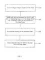
- FIG. 1illustrates a system for removing blurring from a captured image, under an embodiment of the invention.
- FIG. 2illustrates a method for removing blurring from a captured image, under an embodiment of the invention.
- FIG. 3illustrates a method for adjusting individual pixels to remove blurring, under an embodiment of the invention.
- FIGS. 4A and 4Billustrate examples of the blurring quantities determined in FIG. 3 .
- FIG. 5illustrates an analytical method for removing blurring from a captured image, under one embodiment of the invention.
- FIG. 6illustrates a method for removing blurring from an image originally captured on a printed medium, under another embodiment of the invention.
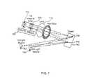
- FIG. 7illustrates a system for removing blurring from a captured image using multiple imaging mediums, under an embodiment of the invention.
- FIG. 8illustrates a prior-art imaging device incorporating a three-dimensional sensor.
- FIG. 9illustrates a basic, prior-art imaging system comprising a lens and an image capturing medium.
- Embodiments of the inventiondescribe a technique for removing blurring from a captured image.
- numerous specific detailsare set forth in order to provide a thorough understanding of the present invention. It will be apparent, however, that the present invention may be practiced without these specific details. In other instances, well-known structures and devices are shown in block diagram form in order to avoid unnecessarily obscuring the present invention.
- the imaging devicemay include a lens and an imaging medium having a plurality of imaging pieces.
- an imageis “captured” when light reflected of a target object is recorded on an imaging medium.
- An “imaging medium”is any medium that can record reflected light for purpose of creating an image of the target object.
- An example of an imaging mediumincludes an array of light-sensitive pixels, as used on digital cameras.
- Another example of an imaging mediumincludes a substrate of film used to form pictures on traditional cameras. In one application, each pixel may record red-blue-green light to form a color or black and white image.
- An “imaging piece”is a discrete portion of an imaging medium that records reflected light from a specific region or point on a target object.
- An example of an imaging pieceis a pixel in an array of pixels.
- each pixel on an array of pixelscaptures light reflected from different regions of the target object.
- each pixel in the arraycaptures light from a corresponding region on the target object.
- multiple pixels that surround one anothercapture light reflected from the same region on the target object.
- an embodiment of the inventionprovides that distances are determined between individual imaging pieces forming an imaging medium and corresponding regions of the target object being imaged by the respective imaging pieces. If the image provided by the imaging piece is in-focus, light reflected from the corresponding region of the target object is captured substantially by that one imaging piece. The image may be captured on the imaging medium using multiple imaging pieces. Blurring may be removed from the captured image using the distances identified for the individual imaging pieces.
- blurringis removed from the captured image by determining, for each individual imaging piece, (i) a primary image component captured from the corresponding region of the target object for that imaging piece and (ii) adjacent image components captured on one or more adjacent imaging pieces to that imaging piece, where each adjacent image component is attributable to the region of the target object that is imaged primarily by the corresponding adjacent imaging piece.
- blurringis removed from a captured image by determining a secondary image component.
- the secondary image componentcorresponds to a region of the target object that has a primary image component captured on one or more of the adjacent imaging pieces to a respective imaging piece being considered.
- removing blurring from the captured imageincludes, for each imaging piece in which the primary image component is determined: (i) adding to a value of the primary image component to compensate for a value of the one or more adjacent image components to that imaging piece; and (ii) subtracting from a value of the primary image component to compensate for a value of the secondary image component captured on that imaging piece.
- FIG. 1illustrates a system for removing blurring from a captured image, under an embodiment of the invention.
- the systemincludes a lens 110 and a pixel array 120 formed by a plurality of pixels 122 .
- the pixel array 120corresponds to an image capturing medium.
- a target object 140is comprised of a plurality of regions 142 , each of which are positioned some distance from lens 110 .
- a field stop 146maybe positioned between lens 110 and the target object 140 .
- the systemis equipped with a three-dimensional sensor to determine the distance between individual pixels 122 in the pixel array 120 and corresponding regions of a target object 140 being imaged by the individual pixel.
- the three-dimensional sensormay be formed by a combination of individual pixels 122 and a light source 152 .
- Each pixel 122may be adapted to detect time-of-flight information for a light beam that is generated by the light source 152 , and reflected off a corresponding region 142 of the target object 140 onto that pixel.
- Each region 142 on target object 140is assumed to correspond to a particular pixel 122 if that region is imaged substantially by that one pixel.
- the light sourcemaybe provided by a laser 152 , which pulses beams to the target object 140 for purpose of reflecting the beams to the pixels 122 .
- a correction mechanism 160is coupled to pixel array 120 to determine the distance between each pixel and its corresponding region 142 on the target object.
- the correction mechanismdetermines the distances using the time-of-flight information indicated by the individual pixels.
- the correction mechanism 160removes or reduces blurriness from out-of-focus images captured on individual pixels 122 using the determined distances.
- the light source 152is a laser that is pulsed to reflect off of the corresponding region 142 of each pixel 122 in pixel array 120 .
- the pixels 122measure both the intensity of the light received from the light source 152 , and the time-of-flight for the light to travel from the light source 152 to the pixel array 120 . In this way, the distance between each pixel 122 and its corresponding region 142 or target object 140 is determined.
- the image captured by an individual pixel 122 for its corresponding target region 142will be blurred. As will be described, the image captured by an individual pixel 122 for its corresponding target region 142 may actually appear on multiple pixels 122 when the captured image is blurred. The distance between that pixel 122 and its corresponding target region 142 will be greater (or less than) the range in distance required for the captured image of that target region 142 to be in focus.
- the correction mechanism 160corrects the blurring of the image captured on each pixel 122 using the distance identified by individual pixels 122 and each pixel's corresponding target region 142 . The result is that the collected image on the pixel array 120 from all of the pixels 122 is corrected so that an image that is captured with blurring become clear.
- correction mechanism 160may be implemented as hardware, firmware, or software. In one embodiment, correction mechanism 160 corresponds to a programmed processor. The correction mechanism 160 may be configured to execute one or more methods described with FIGS. 2-6 . In one particular embodiment, relatively inexpensive integrated circuit design is used to implement the mechanism on pixel array 120 .
- embodiments of the inventioncorrect for blurring without having to adjust the lens 110 , or move the lens 110 relative to the imaging medium 120 . Rather, a distance measured between each pixel 122 and its corresponding target region 142 is used to remove blurring from the image captured by each pixel 122 . Thus, the correction may occur after the image is captured.
- FIG. 2illustrates a method for removing blurring from a captured image, under an embodiment of the invention.
- a methodsuch as described with FIG. 2 may be implemented on a system such as described with FIG. 1 .
- step 210an image is captured on the pixel array 120 . If the image is in focus, then the individual pixels 122 substantially capture an image from only the target region 142 corresponding to that pixel 122 . But, as described herein, when the image is blurred, the image captured from each target region 142 is distributed over multiple pixels 122 .
- a pixel distanceis determined for each pixel 122 of the pixel array 120 .
- the pixel distancemay correspond to a distance between a respective individual pixel and a corresponding region 142 of the target object 140 being imaged on that pixel.
- step 230blurring on each pixel 122 is approximated.
- blurringmay be approximated from the captured image of each target region 142 being distributed over multiple pixels 122 .
- blurringmay be approximated from each pixel 122 having part of the captured image from the target region 142 corresponding to an adjacent pixel 122 .
- step 240the image captured by each pixel 122 is adjusted to remove the blurring approximated on that pixel. This may involve adjusting pixel characteristics that include brightness intensity.
- FIG. 3illustrates a method for adjusting individual pixels to remove blurring, under an embodiment of the invention.
- the methodmay be performed after the image is captured using, for example, the correction mechanism 160 (FIG. 1 ). Steps detailed in FIG. 3 are performed for individual pixels in the imaging array 120 after an image is captured on the pixel array 120 .
- Reference to numerals in FIG. 1is intended to illustrate exemplary components for use with an embodiment of the invention.
- step 310the intensity of a selected pixel 122 forming the pixel array 120 is measured. This value may be measured using light sensors or other components internal to the system.
- the target region 142 of that pixelis captured by multiple pixels.
- the portion of that pixel's target region 142 which is captured by adjacent pixelsis approximated. This portion is one of the values that is attributable to blurring on the selected pixel.
- the selected pixel 122When the image on imaging array 120 is out-of-focus, the selected pixel 122 will contain portions of the image captured from target regions 142 corresponding to other adjacent pixels. In step 330 , the portion of the light intensity measured on the selected pixel 122 which is attributable to the captured image of a target region of one or more adjacent pixels is approximated. This portion is another of the values attributable to blurring on the selected pixel.
- each selected pixel 122is an adjacent pixel for other pixels, and consequently may have portions of captured images corresponding to its adjacent pixel.
- FIGS. 4A and 4Bit is possible, for example, for one pixel to have portions of captured images from a target region 142 of eight adjacent pixels.
- the light intensity or quantity of the selected pixelmay include image contributions from nine target regions 142 , where eight of those regions are for adjacent pixels.
- step 340an in-focus light quantity is determined for the selected pixel 122 . This light quality is based on the measured pixel intensity in step 310 , the blurring quantity approximated in step 320 , and the blurring quantity approximated in step 330 .
- FIGS. 4A and 4Billustrate examples of the blurring quantities determined in FIG. 3 .
- FIGS. 4A and 4Billustrate an imaging array 420 of pixels 422 .
- a selected pixel 422 designated by coordinates (i,j)include eight adjacent pixels 424 , having coordinates (i+1,j), (i+1,j+1), (i+1,j ⁇ 1), (i ⁇ 1,j), (i ⁇ 1,j+1), (i ⁇ 1,j ⁇ 1), (i,j+1), and (i,j ⁇ 1). If only the reflection of the target region of the selected pixel (i,j) 422 is considered, then a captured image portion 440 from the selected pixel's corresponding target region is captured primarily by the selected pixel 422 .
- each of the adjacent pixels 424may contain a portion 432 of the image captured from the region of the target object corresponding to the selected pixel 422 . In an embodiment such as described with FIG. 3 , the portion of the image captured by adjacent pixels 424 is approximated in step 320 .
- FIG. 4Bblurring on selected pixel 422 that is attributable to an image of a target region captured from one of its adjacent pixels (i+1,j) 424 is illustrated.
- Each adjacent pixel 424has its own corresponding target region.
- that adjacent pixel's target regionreflects light that is captured substantially by only that adjacent pixel.
- that adjacent pixel's target regionreflects light that is captured by other pixels, including selected pixel 422 .
- selected pixel 422may have portions of captured images from up to eight other adjacent pixels 424 .
- the captured image portion 440 from the region of the target object corresponding to the selected pixel 422is termed the primary image component for that pixel.
- the portions 432 of the captured image lost to adjacent pixels 424 as a result of blurrinessis termed as an adjacent image component for that pixel.
- the portions 434 as a result of captured images from other adjacent pixelsis termed as a secondary image component for that pixel.
- FIG. 5illustrates an analytical method for removing blurring from a captured image, under one embodiment of the invention.
- the blurring in a captured imagecan be completely removed if the distance between each pixel and that pixel's target region is known.
- the distance between each pixel and that pixel's target regionmay be determined from time-of-flight information obtained from a three-dimensional sensor device, such as described in provisional U.S. patent application Ser. No. 60/157,659.
- a method such as described in FIG. 5assumes that such distances for individual pixels of an imaging device is known.
- the imaging mediumis assumed to be an array of pixels. Reference to numerals in FIG. 1 are provided for illustrative purposes only.
- the Center of Focusis determined for target object 140 positioned a distance from lens 110 .
- Equation (2)f is the focal length, d is the distance between the lens 110 and the pixel array 120 , and s is the Center of Focus.
- step 520the range for each pixel 122 is determined using the time-of-flight information detected for that pixel.
- Equation (3)l′ is the distance between light source 152 and the region 142 of a target object corresponding to that particular pixel 122 .
- the term cis the radius of the Circle of Confusion for the particular pixel.
- the term s′represents the distance from the region of the target object 140 to the lens 110 .
- the term d′represents the distance from lens 110 and a center of the pixel array 120 .
- the matrix Srepresents a matrix of s′ for individual pixels 122 in the array of pixels 120 .
- the radius c of the Circle of Confusionis approximated for individual pixels 122 in the pixel array 120 .
- the radius ccan be derived for when the individual pixel distance S(i,j) to the corresponding region 142 of the target object 140 is greater than the Center of Focus, and when S(i,j) is less than or equal to Center of Focus S.
- a linear system of equationsis determined to solve actual brightness on individual pixels.
- G(i,j)is the ratio of the area of the pixel to the Circle of Confusion for that pixel (i.e., CoC(i,j) of pixel (i,j)).
- H(k,l)is the ratio of the overlapping area of the Circle of Confusion for an adjacent pixel to the pixel (i,j) (i.e., CoC(k,l)), where (k,l) are the indices of those adjacent pixels whose Circle of Confusion overlaps with the pixel at (i,j) position.
- Equation (8)accounts for each pixel's (i) primary image component, corresponding to the measured intensity on a pixel from the amount of light reflected from that pixel's region 142 on target object 140 , and (ii) secondary image component, derived from light reflected by the circle of confusion from adjacent pixels which overlap with that pixel.
- Equations (8)accounts for the fact that light intensity from the Circle of Confusion of any one pixel may not be uniform. It is assumed that the profile of intensity distribution over the circle is known.
- the matrix Aholds coefficients G(i,j) and H(k,l).
- the vector xholds unknown variables RealIntensity(i,j).
- the vector bholds the values provided by MeasuredIntensity(i,j). Both vectors are of the size of (total number of pixels) ⁇ (1).
- step 550the set of linear equations are solved using existing analytical existing techniques, such as Gaussian Elimination, or Successive Over Relaxation (SOR). Since the matrix is band shaped, band matrix inversion routines may be used to obtain the inverse of the matrix in faster execution times.
- existing analytical existing techniquessuch as Gaussian Elimination, or Successive Over Relaxation (SOR). Since the matrix is band shaped, band matrix inversion routines may be used to obtain the inverse of the matrix in faster execution times.
- FIG. 6illustrates a method for removing blurring from an image originally captured on a printed medium.
- the imaging mediumis assumed to be a photographic imaging medium, such as used on cameras that use film.
- the correction mechanism 160couples with the pixels 122 or other sensors of the device to record distances for discrete locations on the film.
- an imageis captured on a printed medium and on a pixel array 120 .
- the printed mediummay correspond to, for example, a photograph.
- the pixel arraymay be positioned adjacent to the printed medium within the same device. Pixels in the pixel array 120 may detect time-of-flight information for a beam of light, as described with FIG. 1 .
- step 620the distance between each of the plurality of discrete locations on the imaging medium used to create the photograph and corresponding regions on the target object being imaged by corresponding pixels of the pixel array 120 is determined.
- light source 152may be used to reflect off the target object.
- the imagemay be captured by the printed medium.
- the pixel array 120may also capture the image, and also record time-of-flight information for each pixel 122 .
- step 630blurring on individual pixels in the array is approximated. Then in step 640 , the digitized image is adjusted to remove blurring from individual pixels.
- FIGS. 1-6describe a three-dimensional sensor being incorporated into an imaging device using pixels that also image the target object
- other embodiments of the inventionmay use separate pixel arrays for purpose of imaging the target object and for purpose of ranging portions of that imaging medium to corresponding regions of the target object.
- FIG. 7illustrates another embodiment in which an imaging device includes a first pixel array 720 , and a second pixel array 725 positioned adjacent to the first pixel array.
- One or more lenses 710may receive light originating from the multiple light sources, including a first light source 752 and a second light source 754 .
- Each pixel array 720 , 725may incorporate a different type of light sensor. Pixels in the first pixel array 720 may be adapted to detect visible light reflected from the target object 740 for purpose of imaging the target object. For example, each pixel may record light in the red-blue-green spectrum to form a color or black and white image. Individual pixels of the second pixel array 725 may be adapted to detect time-of-flight information from a light source being reflected off the target object 740 and onto pixels in the second pixel array 725 . As discussed with other embodiments, the second pixel array 725 may be used for determining the distance between pixels in the second pixel array and regions of the target object 740 corresponding to those pixels.
- Each of those regions 742maybe illuminated primarily on one of the pixels in the first pixel array 720 . Furthermore, light reflected on each of those regions 742 for purpose of determining that region's range is detected primarily by individual pixels in the second pixel array 725 .
- a first light source 752may be used to illuminate target object 740 for first pixel array 720 .
- the first light source 752may, for example, be sunlight, fluorescent, or incandescent in nature.
- a second light source 754may be used to determine range information by reflecting light off the target object 740 and onto the second pixel array 725 .
- the second light source 754may be a laser.
- second pixel array 725may be configured so as to approximate distance information between corresponding pixels in the first pixel array 720 and corresponding regions 742 of the target object 740 .
- the second pixel array 725may be configured to determine distance information for pixels in the second pixel array, but the distance information for each pixel may be applied to pixels in the first pixel array. In either case, approximations of distances determined by pixels in the second pixel array 725 may be used to correct blurriness in the image captured by first pixel array 720 .
- a correction mechanism 760may be coupled to the first pixel array 720 and the second pixel array 725 to correct the blurriness of the target object's image captured on the first pixel array 720 .
- blurrinessmay be corrected in both first pixel array 720 and second pixel array 725 .
- distance approximated by individual pixels in second pixel array 725may, for example, be used to correct blurriness of the light being reflected from the second light source 754 .
- the approximated distancemay then be recalculated based on the correction in the blurriness of the second pixel array 725 .
- the recalculated distancemay then be used to correct for blurriness in the first pixel array 720 .
- time-of-flight informationto detect range information for individual pixels
- other embodimentsmay use other type of information to detect the distance between individual pixels and regions on the target object being imaged by those pixels.
- individual pixelsmay be sensitive to brightness or other light property characteristics.
- the correction mechanism 160FIG. 1 ) may extrapolate the other light property characteristics on each pixel to determine the range of that pixel to the region on the target object being illuminated by that pixel.
Landscapes
- Engineering & Computer Science (AREA)
- Multimedia (AREA)
- Signal Processing (AREA)
- Studio Devices (AREA)
- Image Processing (AREA)
Abstract
Description
1/s+1/d=1/f (1)
If some point of the object is closer or farther away from
s=d*f/(d−f) (2)
Time-of-flight=(l′+s′+d′)/c (3)
Time-of-flight=2*s′/Speed of Light (4)
Then s′ can be expressed as
s′=Time-of-flight*Speed of light/2 (5)
The distance s′ may be determined for each
S(i,j)=Time-of-flight(i,j)*Speed of light/2 (6)
The matrix S represents a matrix of s′ for
C(i,j)=
IfS(i,j)>SthenC(i,j)=a(1−k)/k
IfS(i,j)<=SthenC(i,j)=a(k−1)/(2−k)
Wherek=d*(S(i,j)−f)/(S(i,j)*f) (7)
In the presence of blurring, the distance d may change slightly, but the effect on the Circle of Confusion for each pixel may be assumed to be negligible.
MeasureIntensity(i,j)=H(i,j)*RealIntensity(i,j)+Sum(G(k,l)*RealIntesity(k,l)) (8)
Claims (9)
Priority Applications (1)
| Application Number | Priority Date | Filing Date | Title |
|---|---|---|---|
| US10/079,196US6876775B2 (en) | 2001-02-16 | 2002-02-19 | Technique for removing blurring from a captured image |
Applications Claiming Priority (2)
| Application Number | Priority Date | Filing Date | Title |
|---|---|---|---|
| US26973101P | 2001-02-16 | 2001-02-16 | |
| US10/079,196US6876775B2 (en) | 2001-02-16 | 2002-02-19 | Technique for removing blurring from a captured image |
Publications (2)
| Publication Number | Publication Date |
|---|---|
| US20020114531A1 US20020114531A1 (en) | 2002-08-22 |
| US6876775B2true US6876775B2 (en) | 2005-04-05 |
Family
ID=23028447
Family Applications (1)
| Application Number | Title | Priority Date | Filing Date |
|---|---|---|---|
| US10/079,196Expired - LifetimeUS6876775B2 (en) | 2001-02-16 | 2002-02-19 | Technique for removing blurring from a captured image |
Country Status (3)
| Country | Link |
|---|---|
| US (1) | US6876775B2 (en) |
| AU (1) | AU2002240415A1 (en) |
| WO (1) | WO2002067574A2 (en) |
Cited By (83)
| Publication number | Priority date | Publication date | Assignee | Title |
|---|---|---|---|---|
| US20040202362A1 (en)* | 2001-04-13 | 2004-10-14 | Shinichi Ishikawa | Wafer carrying robot teaching method and teaching plate |
| US20050280892A1 (en)* | 2004-05-28 | 2005-12-22 | Nobuyuki Nagasawa | Examination method and examination apparatus |
| US20080181527A1 (en)* | 2007-01-26 | 2008-07-31 | Samsung Electronics Co., Ltd. | Apparatus and method of restoring image |
| US20090190001A1 (en)* | 2008-01-25 | 2009-07-30 | Cheimets Peter N | Photon counting imaging system |
| US8027029B2 (en) | 2007-11-07 | 2011-09-27 | Magna Electronics Inc. | Object detection and tracking system |
| US20110298704A1 (en)* | 2005-10-21 | 2011-12-08 | Apple Inc. | Three-dimensional imaging and display system |
| CN103262524A (en)* | 2011-06-09 | 2013-08-21 | 郑苍隆 | Auto-focus image system |
| US9092665B2 (en) | 2013-01-30 | 2015-07-28 | Aquifi, Inc | Systems and methods for initializing motion tracking of human hands |
| US9098739B2 (en) | 2012-06-25 | 2015-08-04 | Aquifi, Inc. | Systems and methods for tracking human hands using parts based template matching |
| US9111135B2 (en) | 2012-06-25 | 2015-08-18 | Aquifi, Inc. | Systems and methods for tracking human hands using parts based template matching using corresponding pixels in bounded regions of a sequence of frames that are a specified distance interval from a reference camera |
| US9129155B2 (en) | 2013-01-30 | 2015-09-08 | Aquifi, Inc. | Systems and methods for initializing motion tracking of human hands using template matching within bounded regions determined using a depth map |
| US9298266B2 (en) | 2013-04-02 | 2016-03-29 | Aquifi, Inc. | Systems and methods for implementing three-dimensional (3D) gesture based graphical user interfaces (GUI) that incorporate gesture reactive interface objects |
| US9310891B2 (en) | 2012-09-04 | 2016-04-12 | Aquifi, Inc. | Method and system enabling natural user interface gestures with user wearable glasses |
| US9504920B2 (en) | 2011-04-25 | 2016-11-29 | Aquifi, Inc. | Method and system to create three-dimensional mapping in a two-dimensional game |
| US9507417B2 (en) | 2014-01-07 | 2016-11-29 | Aquifi, Inc. | Systems and methods for implementing head tracking based graphical user interfaces (GUI) that incorporate gesture reactive interface objects |
| US9600078B2 (en) | 2012-02-03 | 2017-03-21 | Aquifi, Inc. | Method and system enabling natural user interface gestures with an electronic system |
| US9619105B1 (en) | 2014-01-30 | 2017-04-11 | Aquifi, Inc. | Systems and methods for gesture based interaction with viewpoint dependent user interfaces |
| US9798388B1 (en) | 2013-07-31 | 2017-10-24 | Aquifi, Inc. | Vibrotactile system to augment 3D input systems |
| US9857868B2 (en) | 2011-03-19 | 2018-01-02 | The Board Of Trustees Of The Leland Stanford Junior University | Method and system for ergonomic touch-free interface |
| US10040481B2 (en) | 2016-05-17 | 2018-08-07 | Magna Electronics Inc. | Vehicle trailer angle detection system using ultrasonic sensors |
| US10137904B2 (en) | 2015-10-14 | 2018-11-27 | Magna Electronics Inc. | Driver assistance system with sensor offset correction |
| US10239446B2 (en) | 2016-07-13 | 2019-03-26 | Magna Electronics Inc. | Vehicle sensing system using daisy chain of sensors |
| US10347129B2 (en) | 2016-12-07 | 2019-07-09 | Magna Electronics Inc. | Vehicle system with truck turn alert |
| US10419723B2 (en) | 2015-06-25 | 2019-09-17 | Magna Electronics Inc. | Vehicle communication system with forward viewing camera and integrated antenna |
| US10462354B2 (en) | 2016-12-09 | 2019-10-29 | Magna Electronics Inc. | Vehicle control system utilizing multi-camera module |
| US10534081B2 (en) | 2016-05-02 | 2020-01-14 | Magna Electronics Inc. | Mounting system for vehicle short range sensors |
| US10571562B2 (en) | 2016-03-25 | 2020-02-25 | Magna Electronics Inc. | Vehicle short range sensing system using RF sensors |
| US10641867B2 (en) | 2016-08-15 | 2020-05-05 | Magna Electronics Inc. | Vehicle radar system with shaped radar antennas |
| US10677894B2 (en) | 2016-09-06 | 2020-06-09 | Magna Electronics Inc. | Vehicle sensing system for classification of vehicle model |
| US10703204B2 (en) | 2016-03-23 | 2020-07-07 | Magna Electronics Inc. | Vehicle driver monitoring system |
| US10708227B2 (en) | 2016-07-19 | 2020-07-07 | Magna Electronics Inc. | Scalable secure gateway for vehicle |
| US10703341B2 (en) | 2017-02-03 | 2020-07-07 | Magna Electronics Inc. | Vehicle sensor housing with theft protection |
| US10768298B2 (en) | 2016-06-14 | 2020-09-08 | Magna Electronics Inc. | Vehicle sensing system with 360 degree near range sensing |
| US10782388B2 (en) | 2017-02-16 | 2020-09-22 | Magna Electronics Inc. | Vehicle radar system with copper PCB |
| US10816666B2 (en) | 2017-11-21 | 2020-10-27 | Magna Electronics Inc. | Vehicle sensing system with calibration/fusion of point cloud partitions |
| US10836376B2 (en) | 2016-09-06 | 2020-11-17 | Magna Electronics Inc. | Vehicle sensing system with enhanced detection of vehicle angle |
| US10852418B2 (en) | 2016-08-24 | 2020-12-01 | Magna Electronics Inc. | Vehicle sensor with integrated radar and image sensors |
| US10870426B2 (en) | 2017-06-22 | 2020-12-22 | Magna Electronics Inc. | Driving assistance system with rear collision mitigation |
| US10877148B2 (en) | 2017-09-07 | 2020-12-29 | Magna Electronics Inc. | Vehicle radar sensing system with enhanced angle resolution using synthesized aperture |
| US10884103B2 (en) | 2017-04-17 | 2021-01-05 | Magna Electronics Inc. | Calibration system for vehicle radar system |
| US10931862B2 (en) | 2017-06-30 | 2021-02-23 | Magna Electronics Inc. | Vehicle system for communication with trailer sensor |
| US10933798B2 (en) | 2017-09-22 | 2021-03-02 | Magna Electronics Inc. | Vehicle lighting control system with fog detection |
| US10962641B2 (en) | 2017-09-07 | 2021-03-30 | Magna Electronics Inc. | Vehicle radar sensing system with enhanced accuracy using interferometry techniques |
| US10962638B2 (en) | 2017-09-07 | 2021-03-30 | Magna Electronics Inc. | Vehicle radar sensing system with surface modeling |
| US11027654B2 (en) | 2015-12-04 | 2021-06-08 | Magna Electronics Inc. | Vehicle vision system with compressed video transfer via DSRC link |
| US11047977B2 (en) | 2018-02-20 | 2021-06-29 | Magna Electronics Inc. | Vehicle radar system with solution for ADC saturation |
| US11096301B2 (en) | 2019-01-03 | 2021-08-17 | Magna Electronics Inc. | Vehicular radar sensor with mechanical coupling of sensor housing |
| US11142200B2 (en) | 2017-02-23 | 2021-10-12 | Magna Electronics Inc. | Vehicular adaptive cruise control with enhanced vehicle control |
| US11150342B2 (en) | 2017-09-07 | 2021-10-19 | Magna Electronics Inc. | Vehicle radar sensing system with surface segmentation using interferometric statistical analysis |
| US11167771B2 (en) | 2018-01-05 | 2021-11-09 | Magna Mirrors Of America, Inc. | Vehicular gesture monitoring system |
| US11199611B2 (en) | 2018-02-20 | 2021-12-14 | Magna Electronics Inc. | Vehicle radar system with T-shaped slot antennas |
| US11267393B2 (en) | 2019-05-16 | 2022-03-08 | Magna Electronics Inc. | Vehicular alert system for alerting drivers of other vehicles responsive to a change in driving conditions |
| US11294028B2 (en) | 2019-01-29 | 2022-04-05 | Magna Electronics Inc. | Sensing system with enhanced electrical contact at PCB-waveguide interface |
| US11332124B2 (en) | 2019-01-10 | 2022-05-17 | Magna Electronics Inc. | Vehicular control system |
| US11391826B2 (en) | 2017-09-27 | 2022-07-19 | Magna Electronics Inc. | Vehicle LIDAR sensor calibration system |
| US11454719B2 (en) | 2016-07-08 | 2022-09-27 | Magna Electronics Inc. | 2D MIMO radar system for vehicle |
| US11454720B2 (en) | 2018-11-28 | 2022-09-27 | Magna Electronics Inc. | Vehicle radar system with enhanced wave guide antenna system |
| US11486968B2 (en) | 2017-11-15 | 2022-11-01 | Magna Electronics Inc. | Vehicle Lidar sensing system with sensor module |
| US11536829B2 (en) | 2017-02-16 | 2022-12-27 | Magna Electronics Inc. | Vehicle radar system with radar embedded into radome |
| US11609304B2 (en) | 2019-02-07 | 2023-03-21 | Magna Electronics Inc. | Vehicular front camera testing system |
| US11638362B2 (en) | 2018-10-29 | 2023-04-25 | Magna Electronics Inc. | Vehicular radar sensor with enhanced housing and PCB construction |
| US11683911B2 (en) | 2018-10-26 | 2023-06-20 | Magna Electronics Inc. | Vehicular sensing device with cooling feature |
| US11749105B2 (en) | 2020-10-01 | 2023-09-05 | Magna Electronics Inc. | Vehicular communication system with turn signal identification |
| US11808876B2 (en) | 2018-10-25 | 2023-11-07 | Magna Electronics Inc. | Vehicular radar system with vehicle to infrastructure communication |
| US11823395B2 (en) | 2020-07-02 | 2023-11-21 | Magna Electronics Inc. | Vehicular vision system with road contour detection feature |
| US11866063B2 (en) | 2020-01-10 | 2024-01-09 | Magna Electronics Inc. | Communication system and method |
| EP4301626A1 (en) | 2021-03-01 | 2024-01-10 | Magna Mirrors Of America, Inc. | Interior rearview mirror assembly with driver monitoring system |
| US12007476B2 (en) | 2021-09-13 | 2024-06-11 | Magna Electronics Inc. | Method for detecting objects via a vehicular sensing system |
| US12013480B2 (en) | 2020-06-05 | 2024-06-18 | Magna Electronics Inc. | Vehicular radar sensor with waveguide connection embedded in PCB |
| US12030501B2 (en) | 2020-10-02 | 2024-07-09 | Magna Electronics Inc. | Vehicular control system with enhanced vehicle passing maneuvering |
| US12036990B2 (en) | 2019-11-22 | 2024-07-16 | Magna Electronics Inc. | Vehicular control system with controlled vehicle stopping and starting at intersection |
| US12044794B2 (en) | 2019-02-26 | 2024-07-23 | Magna Electronics Inc. | Vehicular radar system with automatic sensor alignment |
| US12071084B2 (en) | 2020-02-14 | 2024-08-27 | Magna Electronics Inc. | Vehicular sensing system with variable power mode for thermal management |
| US12117555B2 (en) | 2020-12-11 | 2024-10-15 | Magna Mirrors Of America, Inc. | Vehicular exterior door handle assembly with radar module and enhanced thermal management |
| US12122324B2 (en) | 2021-09-17 | 2024-10-22 | Magna Mirrors Of America, Inc. | Vehicular power door sensing and operating system |
| US12194992B2 (en) | 2021-07-01 | 2025-01-14 | Magna Electronics Inc. | Vehicular automatic emergency braking system with cross-path threat determination |
| US12252172B2 (en) | 2021-09-21 | 2025-03-18 | Magna Electronics Inc. | Vehicular intelligent remote parking assist system |
| US12286102B2 (en) | 2022-04-27 | 2025-04-29 | Magna Electronics Inc. | Vehicular driving assist system with collision avoidance |
| US12345809B2 (en)* | 2022-04-20 | 2025-07-01 | Magna Electronics Inc. | Vehicular radar sensor with antenna that provides improved blind-spot detection |
| US12366653B2 (en) | 2021-10-26 | 2025-07-22 | Magna Electronics Inc. | Radar-based vehicular exterior mirror collision avoidance system |
| US12371027B2 (en) | 2019-08-23 | 2025-07-29 | Magna Electronics Inc. | Vehicular driving assist system with traffic jam probability determination |
| US12385315B2 (en) | 2022-07-22 | 2025-08-12 | Magna Mirrors Of America, Inc. | Vehicular closure opening device using a micro-lens array at closure panel |
| US12420707B2 (en) | 2022-06-24 | 2025-09-23 | Magna Electronics Inc. | Vehicular control system with cross traffic alert and collision avoidance |
Families Citing this family (6)
| Publication number | Priority date | Publication date | Assignee | Title |
|---|---|---|---|---|
| JP4279562B2 (en)* | 2003-01-17 | 2009-06-17 | 富士フイルム株式会社 | Control method for solid-state imaging device |
| JP4025207B2 (en)* | 2003-01-17 | 2007-12-19 | 富士フイルム株式会社 | Solid-state image sensor and digital camera |
| US7139067B2 (en)* | 2003-09-12 | 2006-11-21 | Textron Systems Corporation | Three-dimensional imaging with multiframe blind deconvolution |
| CN100490505C (en)* | 2004-02-13 | 2009-05-20 | 索尼株式会社 | Image processing device and image processing method |
| EP1624672A1 (en)* | 2004-08-07 | 2006-02-08 | STMicroelectronics Limited | A method of determining a measure of edge strength and focus |
| KR100801087B1 (en)* | 2006-07-05 | 2008-02-11 | 삼성전자주식회사 | Moving object detection system and method using structured light, Mobile robot including the system |
Citations (32)
| Publication number | Priority date | Publication date | Assignee | Title |
|---|---|---|---|---|
| US3857022A (en) | 1973-11-15 | 1974-12-24 | Integrated Sciences Corp | Graphic input device |
| US4187492A (en) | 1976-11-18 | 1980-02-05 | Institut Francais Du Petrole | Device for determining the relative position of elongate members towed behind a ship |
| EP0042500A1 (en) | 1980-06-20 | 1981-12-30 | BASF Lacke + Farben AG | Baking-enamel |
| US4312053A (en) | 1971-12-03 | 1982-01-19 | Subcom, Inc. | Range and depth detection system |
| US4333170A (en) | 1977-11-21 | 1982-06-01 | Northrop Corporation | Acoustical detection and tracking system |
| US4376301A (en) | 1980-12-10 | 1983-03-08 | Chevron Research Company | Seismic streamer locator |
| WO1984000427A1 (en) | 1982-07-10 | 1984-02-02 | Syrinx Precision Instr | Data input device |
| US4686655A (en) | 1970-12-28 | 1987-08-11 | Hyatt Gilbert P | Filtering system for processing signature signals |
| EP0233464A1 (en) | 1986-01-21 | 1987-08-26 | Siemens Aktiengesellschaft | Circuit for reading an optoelectronic image sensor |
| US4716542A (en) | 1985-09-26 | 1987-12-29 | Timberline Software Corporation | Method and apparatus for single source entry of analog and digital data into a computer |
| US4956824A (en) | 1989-09-12 | 1990-09-11 | Science Accessories Corp. | Position determination apparatus |
| US4980870A (en) | 1988-06-10 | 1990-12-25 | Spivey Brett A | Array compensating beamformer |
| US5056791A (en) | 1989-09-28 | 1991-10-15 | Nannette Poillon | Golf simulator and analyzer system |
| US5099456A (en) | 1990-06-13 | 1992-03-24 | Hughes Aircraft Company | Passive locating system |
| US5166905A (en) | 1991-10-21 | 1992-11-24 | Texaco Inc. | Means and method for dynamically locating positions on a marine seismic streamer cable |
| US5174759A (en) | 1988-08-04 | 1992-12-29 | Preston Frank S | TV animation interactively controlled by the viewer through input above a book page |
| US5193124A (en)* | 1989-06-29 | 1993-03-09 | The Research Foundation Of State University Of New York | Computational methods and electronic camera apparatus for determining distance of objects, rapid autofocusing, and obtaining improved focus images |
| US5291300A (en)* | 1991-01-25 | 1994-03-01 | Victor Company Of Japan, Ltd. | Motion vector detecting apparatus for detecting motion of image to prevent disturbance thereof |
| EP0629964A1 (en) | 1993-01-27 | 1994-12-21 | Texas Instruments Incorporated | Method of synthesizing optical images |
| US5459542A (en)* | 1992-12-25 | 1995-10-17 | Canon Kabushiki Kaisha | Image-blur preventing apparatus |
| US5510894A (en)* | 1988-12-22 | 1996-04-23 | Renishaw Plc | Spectroscopic apparatus and methods |
| US5534991A (en)* | 1992-03-13 | 1996-07-09 | Canon Kabushiki Kaisha | Active distance measuring apparatus |
| US5573077A (en) | 1990-11-16 | 1996-11-12 | Knowles; Terence J. | Acoustic touch position sensor |
| US5576975A (en)* | 1991-09-20 | 1996-11-19 | Fujitsu Limited | Distance measuring method and a distance measuring apparatus |
| US5617371A (en) | 1995-02-08 | 1997-04-01 | Diagnostic/Retrieval Systems, Inc. | Method and apparatus for accurately determing the location of signal transducers in a passive sonar or other transducer array system |
| US5825033A (en) | 1996-10-31 | 1998-10-20 | The Arizona Board Of Regents On Behalf Of The University Of Arizona | Signal processing method for gamma-ray semiconductor sensor |
| US6002435A (en) | 1996-04-01 | 1999-12-14 | Hamamatsu Photonics K.K. | Solid-state imaging apparatus |
| EP0982676A1 (en) | 1998-08-27 | 2000-03-01 | Hewlett-Packard Company | A method and apparatus for a virtual display/keyboard for a PDA |
| WO2000019705A1 (en) | 1998-09-28 | 2000-04-06 | 3Dv Systems, Ltd. | Distance measurement with a camera |
| EP1039365A2 (en) | 1999-03-26 | 2000-09-27 | Nokia Mobile Phones Ltd. | An input arrangement for manual entry of data and a mobile phone |
| EP1045586A2 (en) | 1999-04-14 | 2000-10-18 | Canon Kabushiki Kaisha | Image processing apparatus |
| US6201517B1 (en)* | 1997-02-27 | 2001-03-13 | Minolta Co., Ltd. | Stereoscopic image display apparatus |
- 2002
- 2002-02-19WOPCT/US2002/004840patent/WO2002067574A2/ennot_activeApplication Discontinuation
- 2002-02-19USUS10/079,196patent/US6876775B2/ennot_activeExpired - Lifetime
- 2002-02-19AUAU2002240415Apatent/AU2002240415A1/ennot_activeAbandoned
Patent Citations (32)
| Publication number | Priority date | Publication date | Assignee | Title |
|---|---|---|---|---|
| US4686655A (en) | 1970-12-28 | 1987-08-11 | Hyatt Gilbert P | Filtering system for processing signature signals |
| US4312053A (en) | 1971-12-03 | 1982-01-19 | Subcom, Inc. | Range and depth detection system |
| US3857022A (en) | 1973-11-15 | 1974-12-24 | Integrated Sciences Corp | Graphic input device |
| US4187492A (en) | 1976-11-18 | 1980-02-05 | Institut Francais Du Petrole | Device for determining the relative position of elongate members towed behind a ship |
| US4333170A (en) | 1977-11-21 | 1982-06-01 | Northrop Corporation | Acoustical detection and tracking system |
| EP0042500A1 (en) | 1980-06-20 | 1981-12-30 | BASF Lacke + Farben AG | Baking-enamel |
| US4376301A (en) | 1980-12-10 | 1983-03-08 | Chevron Research Company | Seismic streamer locator |
| WO1984000427A1 (en) | 1982-07-10 | 1984-02-02 | Syrinx Precision Instr | Data input device |
| US4716542A (en) | 1985-09-26 | 1987-12-29 | Timberline Software Corporation | Method and apparatus for single source entry of analog and digital data into a computer |
| EP0233464A1 (en) | 1986-01-21 | 1987-08-26 | Siemens Aktiengesellschaft | Circuit for reading an optoelectronic image sensor |
| US4980870A (en) | 1988-06-10 | 1990-12-25 | Spivey Brett A | Array compensating beamformer |
| US5174759A (en) | 1988-08-04 | 1992-12-29 | Preston Frank S | TV animation interactively controlled by the viewer through input above a book page |
| US5510894A (en)* | 1988-12-22 | 1996-04-23 | Renishaw Plc | Spectroscopic apparatus and methods |
| US5193124A (en)* | 1989-06-29 | 1993-03-09 | The Research Foundation Of State University Of New York | Computational methods and electronic camera apparatus for determining distance of objects, rapid autofocusing, and obtaining improved focus images |
| US4956824A (en) | 1989-09-12 | 1990-09-11 | Science Accessories Corp. | Position determination apparatus |
| US5056791A (en) | 1989-09-28 | 1991-10-15 | Nannette Poillon | Golf simulator and analyzer system |
| US5099456A (en) | 1990-06-13 | 1992-03-24 | Hughes Aircraft Company | Passive locating system |
| US5573077A (en) | 1990-11-16 | 1996-11-12 | Knowles; Terence J. | Acoustic touch position sensor |
| US5291300A (en)* | 1991-01-25 | 1994-03-01 | Victor Company Of Japan, Ltd. | Motion vector detecting apparatus for detecting motion of image to prevent disturbance thereof |
| US5576975A (en)* | 1991-09-20 | 1996-11-19 | Fujitsu Limited | Distance measuring method and a distance measuring apparatus |
| US5166905A (en) | 1991-10-21 | 1992-11-24 | Texaco Inc. | Means and method for dynamically locating positions on a marine seismic streamer cable |
| US5534991A (en)* | 1992-03-13 | 1996-07-09 | Canon Kabushiki Kaisha | Active distance measuring apparatus |
| US5459542A (en)* | 1992-12-25 | 1995-10-17 | Canon Kabushiki Kaisha | Image-blur preventing apparatus |
| EP0629964A1 (en) | 1993-01-27 | 1994-12-21 | Texas Instruments Incorporated | Method of synthesizing optical images |
| US5617371A (en) | 1995-02-08 | 1997-04-01 | Diagnostic/Retrieval Systems, Inc. | Method and apparatus for accurately determing the location of signal transducers in a passive sonar or other transducer array system |
| US6002435A (en) | 1996-04-01 | 1999-12-14 | Hamamatsu Photonics K.K. | Solid-state imaging apparatus |
| US5825033A (en) | 1996-10-31 | 1998-10-20 | The Arizona Board Of Regents On Behalf Of The University Of Arizona | Signal processing method for gamma-ray semiconductor sensor |
| US6201517B1 (en)* | 1997-02-27 | 2001-03-13 | Minolta Co., Ltd. | Stereoscopic image display apparatus |
| EP0982676A1 (en) | 1998-08-27 | 2000-03-01 | Hewlett-Packard Company | A method and apparatus for a virtual display/keyboard for a PDA |
| WO2000019705A1 (en) | 1998-09-28 | 2000-04-06 | 3Dv Systems, Ltd. | Distance measurement with a camera |
| EP1039365A2 (en) | 1999-03-26 | 2000-09-27 | Nokia Mobile Phones Ltd. | An input arrangement for manual entry of data and a mobile phone |
| EP1045586A2 (en) | 1999-04-14 | 2000-10-18 | Canon Kabushiki Kaisha | Image processing apparatus |
Non-Patent Citations (6)
| Title |
|---|
| A. E. Savakis et al., "Restoration of Real Defocused Images Using Blur Models Based on Geometrical and Diffraction Optics," 1991, IEEE, pp. 919-922. |
| IBM Corp., "Virtual Keyboard" ISB Tech Disclosure Bulletin, Mar. 1990, vol. 32, No. 10B, XP 000097915, pp. 359-360. |
| International Preliminary Examination Report, Oct. 20, 2003. |
| International Search Report, Oct. 21, 2002. |
| Naoshi Matsuo et al., "Speaker Position Detection System Using Audio-visual Information," Dec. 1999, XP 000931599, pp. 214-220. |
| Ren C. Luo et al., "Defocusing Blur Restoration in Natural Scene Images for Factual Analysis," Nov. 15, 1993, IEEE, pp. 1377-1381. |
Cited By (141)
| Publication number | Priority date | Publication date | Assignee | Title |
|---|---|---|---|---|
| US20040202362A1 (en)* | 2001-04-13 | 2004-10-14 | Shinichi Ishikawa | Wafer carrying robot teaching method and teaching plate |
| US20050280892A1 (en)* | 2004-05-28 | 2005-12-22 | Nobuyuki Nagasawa | Examination method and examination apparatus |
| US20070115543A1 (en)* | 2004-05-28 | 2007-05-24 | Nobuyuki Nagasawa | Examination method and examination apparatus |
| US20080106786A1 (en)* | 2004-05-28 | 2008-05-08 | Nobuyuki Nagasawa | Examination method and examination apparatus |
| US9958960B2 (en) | 2005-10-21 | 2018-05-01 | Apple Inc. | Three-dimensional imaging and display system |
| US8743345B2 (en)* | 2005-10-21 | 2014-06-03 | Apple Inc. | Three-dimensional imaging and display system |
| US9766716B2 (en) | 2005-10-21 | 2017-09-19 | Apple Inc. | Three-dimensional imaging and display system |
| US20110298704A1 (en)* | 2005-10-21 | 2011-12-08 | Apple Inc. | Three-dimensional imaging and display system |
| US20110298798A1 (en)* | 2005-10-21 | 2011-12-08 | Apple Inc. | Three-dimensional imaging and display system |
| US8780332B2 (en)* | 2005-10-21 | 2014-07-15 | Apple Inc. | Three-dimensional imaging and display system |
| US20080181527A1 (en)* | 2007-01-26 | 2008-07-31 | Samsung Electronics Co., Ltd. | Apparatus and method of restoring image |
| US8055089B2 (en) | 2007-01-26 | 2011-11-08 | Samsung Electronics Co., Ltd. | Apparatus and method of restoring image |
| US8767186B2 (en) | 2007-11-07 | 2014-07-01 | Magna Electronics Inc. | Object detection system |
| US8027029B2 (en) | 2007-11-07 | 2011-09-27 | Magna Electronics Inc. | Object detection and tracking system |
| US11346951B2 (en) | 2007-11-07 | 2022-05-31 | Magna Electronics Inc. | Object detection system |
| US10295667B2 (en) | 2007-11-07 | 2019-05-21 | Magna Electronics Inc. | Object detection system |
| US9383445B2 (en) | 2007-11-07 | 2016-07-05 | Magna Electronics Inc. | Object detection system |
| US20090190001A1 (en)* | 2008-01-25 | 2009-07-30 | Cheimets Peter N | Photon counting imaging system |
| US7961224B2 (en) | 2008-01-25 | 2011-06-14 | Peter N. Cheimets | Photon counting imaging system |
| US9857868B2 (en) | 2011-03-19 | 2018-01-02 | The Board Of Trustees Of The Leland Stanford Junior University | Method and system for ergonomic touch-free interface |
| US9504920B2 (en) | 2011-04-25 | 2016-11-29 | Aquifi, Inc. | Method and system to create three-dimensional mapping in a two-dimensional game |
| CN103262524A (en)* | 2011-06-09 | 2013-08-21 | 郑苍隆 | Auto-focus image system |
| CN103262524B (en)* | 2011-06-09 | 2018-01-05 | 郑苍隆 | Automatic focusedimage system |
| US9600078B2 (en) | 2012-02-03 | 2017-03-21 | Aquifi, Inc. | Method and system enabling natural user interface gestures with an electronic system |
| US9098739B2 (en) | 2012-06-25 | 2015-08-04 | Aquifi, Inc. | Systems and methods for tracking human hands using parts based template matching |
| US9111135B2 (en) | 2012-06-25 | 2015-08-18 | Aquifi, Inc. | Systems and methods for tracking human hands using parts based template matching using corresponding pixels in bounded regions of a sequence of frames that are a specified distance interval from a reference camera |
| US9310891B2 (en) | 2012-09-04 | 2016-04-12 | Aquifi, Inc. | Method and system enabling natural user interface gestures with user wearable glasses |
| US9129155B2 (en) | 2013-01-30 | 2015-09-08 | Aquifi, Inc. | Systems and methods for initializing motion tracking of human hands using template matching within bounded regions determined using a depth map |
| US9092665B2 (en) | 2013-01-30 | 2015-07-28 | Aquifi, Inc | Systems and methods for initializing motion tracking of human hands |
| US9298266B2 (en) | 2013-04-02 | 2016-03-29 | Aquifi, Inc. | Systems and methods for implementing three-dimensional (3D) gesture based graphical user interfaces (GUI) that incorporate gesture reactive interface objects |
| US9798388B1 (en) | 2013-07-31 | 2017-10-24 | Aquifi, Inc. | Vibrotactile system to augment 3D input systems |
| US9507417B2 (en) | 2014-01-07 | 2016-11-29 | Aquifi, Inc. | Systems and methods for implementing head tracking based graphical user interfaces (GUI) that incorporate gesture reactive interface objects |
| US9619105B1 (en) | 2014-01-30 | 2017-04-11 | Aquifi, Inc. | Systems and methods for gesture based interaction with viewpoint dependent user interfaces |
| US10855953B2 (en) | 2015-06-25 | 2020-12-01 | Magna Electronics Inc. | Vehicular control system with forward viewing camera and beam emitting antenna array |
| US10419723B2 (en) | 2015-06-25 | 2019-09-17 | Magna Electronics Inc. | Vehicle communication system with forward viewing camera and integrated antenna |
| US11805228B2 (en) | 2015-06-25 | 2023-10-31 | Magna Electronics Inc. | Vehicular control system with forward viewing camera and forward sensing sensor |
| US11533454B2 (en) | 2015-06-25 | 2022-12-20 | Magna Electronics Inc. | Vehicular control system with forward viewing camera and forward sensing sensor |
| US11134220B2 (en) | 2015-06-25 | 2021-09-28 | Magna Electronics Inc. | Vehicular control system with forward viewing camera and forward and rearward sensing sensors |
| US10137904B2 (en) | 2015-10-14 | 2018-11-27 | Magna Electronics Inc. | Driver assistance system with sensor offset correction |
| US11702088B2 (en) | 2015-10-14 | 2023-07-18 | Magna Electronics Inc. | Vehicular driving assist system with sensor offset correction |
| US10773729B2 (en) | 2015-10-14 | 2020-09-15 | Magna Electronics Inc. | Driver assistance system with sensor offset correction |
| US12024181B2 (en) | 2015-10-14 | 2024-07-02 | Magna Electronics Inc. | Vehicular driving assist system with sensor offset correction |
| US11027654B2 (en) | 2015-12-04 | 2021-06-08 | Magna Electronics Inc. | Vehicle vision system with compressed video transfer via DSRC link |
| US10703204B2 (en) | 2016-03-23 | 2020-07-07 | Magna Electronics Inc. | Vehicle driver monitoring system |
| US11872884B2 (en) | 2016-03-23 | 2024-01-16 | Magna Electronics Inc. | Vehicular driver monitoring system |
| US11156711B2 (en) | 2016-03-25 | 2021-10-26 | Magna Electronics Inc. | Vehicular sensing system using RF sensors |
| US10571562B2 (en) | 2016-03-25 | 2020-02-25 | Magna Electronics Inc. | Vehicle short range sensing system using RF sensors |
| US11747469B2 (en) | 2016-03-25 | 2023-09-05 | Magna Electronics Inc. | Vehicular sensing system using MIMO radar sensor units |
| US10534081B2 (en) | 2016-05-02 | 2020-01-14 | Magna Electronics Inc. | Mounting system for vehicle short range sensors |
| US11294049B2 (en) | 2016-05-02 | 2022-04-05 | Magna Electronics Inc. | Mounting system for vehicular sensors |
| US10040481B2 (en) | 2016-05-17 | 2018-08-07 | Magna Electronics Inc. | Vehicle trailer angle detection system using ultrasonic sensors |
| US10768298B2 (en) | 2016-06-14 | 2020-09-08 | Magna Electronics Inc. | Vehicle sensing system with 360 degree near range sensing |
| US11275175B2 (en) | 2016-06-14 | 2022-03-15 | Magna Electronics Inc. | Method for detecting objects via a vehicular sensing system |
| US11454719B2 (en) | 2016-07-08 | 2022-09-27 | Magna Electronics Inc. | 2D MIMO radar system for vehicle |
| US11971475B2 (en) | 2016-07-08 | 2024-04-30 | Magna Electronics Inc. | 2D MIMO vehicular radar sensing system |
| US10239446B2 (en) | 2016-07-13 | 2019-03-26 | Magna Electronics Inc. | Vehicle sensing system using daisy chain of sensors |
| US10518699B2 (en) | 2016-07-13 | 2019-12-31 | Magna Electronics Inc. | Vehicle sensing system using chain of sensors |
| US11463408B2 (en) | 2016-07-19 | 2022-10-04 | Magna Electronics Inc. | Vehicular secure gateway system |
| US10708227B2 (en) | 2016-07-19 | 2020-07-07 | Magna Electronics Inc. | Scalable secure gateway for vehicle |
| US10641867B2 (en) | 2016-08-15 | 2020-05-05 | Magna Electronics Inc. | Vehicle radar system with shaped radar antennas |
| US10845462B2 (en) | 2016-08-15 | 2020-11-24 | Magna Electronics Inc. | Vehicle radar system with shaped antennas |
| US11714165B2 (en) | 2016-08-15 | 2023-08-01 | Magna Electronics Inc. | Method for determining presence of an object via a vehicular radar system with shaped antennas |
| US11719808B2 (en) | 2016-08-24 | 2023-08-08 | Magna Electronics Inc. | Vehicle sensor with integrated radar and image sensors |
| US10852418B2 (en) | 2016-08-24 | 2020-12-01 | Magna Electronics Inc. | Vehicle sensor with integrated radar and image sensors |
| US11597378B2 (en) | 2016-09-06 | 2023-03-07 | Magna Electronics Inc. | Vehicular sensing system for anticipating cut-in by other vehicle |
| US11604253B2 (en) | 2016-09-06 | 2023-03-14 | Magna Electronics Inc. | Vehicular sensing system for classification of detected objects |
| US10866310B2 (en) | 2016-09-06 | 2020-12-15 | Magna Electronics Inc. | Vehicle sensing system for classification of vehicle model |
| US10836376B2 (en) | 2016-09-06 | 2020-11-17 | Magna Electronics Inc. | Vehicle sensing system with enhanced detection of vehicle angle |
| US10677894B2 (en) | 2016-09-06 | 2020-06-09 | Magna Electronics Inc. | Vehicle sensing system for classification of vehicle model |
| US11884261B2 (en) | 2016-09-06 | 2024-01-30 | Magna Electronics Inc. | Vehicular trailer sway management system |
| US11727807B2 (en) | 2016-12-07 | 2023-08-15 | Magna Electronics Inc. | Vehicular control system with collision avoidance |
| US11138883B2 (en) | 2016-12-07 | 2021-10-05 | Magna Electronics Inc. | Vehicular communication system with collision alert |
| US10347129B2 (en) | 2016-12-07 | 2019-07-09 | Magna Electronics Inc. | Vehicle system with truck turn alert |
| US10462354B2 (en) | 2016-12-09 | 2019-10-29 | Magna Electronics Inc. | Vehicle control system utilizing multi-camera module |
| US10703341B2 (en) | 2017-02-03 | 2020-07-07 | Magna Electronics Inc. | Vehicle sensor housing with theft protection |
| US10782388B2 (en) | 2017-02-16 | 2020-09-22 | Magna Electronics Inc. | Vehicle radar system with copper PCB |
| US11422228B2 (en) | 2017-02-16 | 2022-08-23 | Magna Electronics Inc. | Method for constructing vehicular radar sensor with copper PCB |
| US11536829B2 (en) | 2017-02-16 | 2022-12-27 | Magna Electronics Inc. | Vehicle radar system with radar embedded into radome |
| US11142200B2 (en) | 2017-02-23 | 2021-10-12 | Magna Electronics Inc. | Vehicular adaptive cruise control with enhanced vehicle control |
| US10884103B2 (en) | 2017-04-17 | 2021-01-05 | Magna Electronics Inc. | Calibration system for vehicle radar system |
| US11555888B2 (en) | 2017-04-17 | 2023-01-17 | Magna Electronics Inc. | System and method for calibrating vehicular radar sensing system |
| US11981329B2 (en) | 2017-06-22 | 2024-05-14 | Magna Electronics Inc. | Vehicular control system with passing control function |
| US11713038B2 (en) | 2017-06-22 | 2023-08-01 | Magna Electronics Inc. | Vehicular control system with rear collision mitigation |
| US10870426B2 (en) | 2017-06-22 | 2020-12-22 | Magna Electronics Inc. | Driving assistance system with rear collision mitigation |
| US11472403B2 (en) | 2017-06-22 | 2022-10-18 | Magna Electronics Inc. | Vehicular control system with rear collision mitigation |
| US10931862B2 (en) | 2017-06-30 | 2021-02-23 | Magna Electronics Inc. | Vehicle system for communication with trailer sensor |
| US10962638B2 (en) | 2017-09-07 | 2021-03-30 | Magna Electronics Inc. | Vehicle radar sensing system with surface modeling |
| US12025696B2 (en) | 2017-09-07 | 2024-07-02 | Magna Electronics Inc. | Vehicle radar sensing system with enhanced angle resolution |
| US10962641B2 (en) | 2017-09-07 | 2021-03-30 | Magna Electronics Inc. | Vehicle radar sensing system with enhanced accuracy using interferometry techniques |
| US11867802B2 (en) | 2017-09-07 | 2024-01-09 | Magna Electronics Inc. | Vehicle radar sensing system |
| US11150342B2 (en) | 2017-09-07 | 2021-10-19 | Magna Electronics Inc. | Vehicle radar sensing system with surface segmentation using interferometric statistical analysis |
| US10877148B2 (en) | 2017-09-07 | 2020-12-29 | Magna Electronics Inc. | Vehicle radar sensing system with enhanced angle resolution using synthesized aperture |
| US11703587B2 (en) | 2017-09-07 | 2023-07-18 | Magna Electronics Inc. | Vehicle radar sensing system with enhanced angle resolution |
| US10933798B2 (en) | 2017-09-22 | 2021-03-02 | Magna Electronics Inc. | Vehicle lighting control system with fog detection |
| US11391826B2 (en) | 2017-09-27 | 2022-07-19 | Magna Electronics Inc. | Vehicle LIDAR sensor calibration system |
| US11486968B2 (en) | 2017-11-15 | 2022-11-01 | Magna Electronics Inc. | Vehicle Lidar sensing system with sensor module |
| US11442168B2 (en) | 2017-11-21 | 2022-09-13 | Magna Electronics Inc. | Vehicular driving assist system with lidar sensors that emit different patterns of light |
| US10816666B2 (en) | 2017-11-21 | 2020-10-27 | Magna Electronics Inc. | Vehicle sensing system with calibration/fusion of point cloud partitions |
| US12007484B2 (en) | 2017-11-21 | 2024-06-11 | Magna Electronics Inc. | Vehicular driving assist system with lidar sensors that emit light at different pulse rates |
| US11167771B2 (en) | 2018-01-05 | 2021-11-09 | Magna Mirrors Of America, Inc. | Vehicular gesture monitoring system |
| US12054169B2 (en) | 2018-01-05 | 2024-08-06 | Magna Mirrors Of America, Inc. | Vehicular cabin monitoring system |
| US11648956B2 (en) | 2018-01-05 | 2023-05-16 | Magna Mirrors Of America, Inc. | Vehicular cabin monitoring system |
| US11199611B2 (en) | 2018-02-20 | 2021-12-14 | Magna Electronics Inc. | Vehicle radar system with T-shaped slot antennas |
| US11733376B2 (en) | 2018-02-20 | 2023-08-22 | Magna Electronics Inc. | Vehicle radar system with solution for ADC saturation |
| US11714164B2 (en) | 2018-02-20 | 2023-08-01 | Magna Electronics Inc. | Vehicle radar system with t-shaped slot antennas |
| US11047977B2 (en) | 2018-02-20 | 2021-06-29 | Magna Electronics Inc. | Vehicle radar system with solution for ADC saturation |
| US11808876B2 (en) | 2018-10-25 | 2023-11-07 | Magna Electronics Inc. | Vehicular radar system with vehicle to infrastructure communication |
| US11683911B2 (en) | 2018-10-26 | 2023-06-20 | Magna Electronics Inc. | Vehicular sensing device with cooling feature |
| US11638362B2 (en) | 2018-10-29 | 2023-04-25 | Magna Electronics Inc. | Vehicular radar sensor with enhanced housing and PCB construction |
| US11852720B2 (en) | 2018-11-28 | 2023-12-26 | Magna Electronics Inc. | Vehicle radar system with enhanced wave guide antenna system |
| US11454720B2 (en) | 2018-11-28 | 2022-09-27 | Magna Electronics Inc. | Vehicle radar system with enhanced wave guide antenna system |
| US11096301B2 (en) | 2019-01-03 | 2021-08-17 | Magna Electronics Inc. | Vehicular radar sensor with mechanical coupling of sensor housing |
| US11647602B2 (en) | 2019-01-03 | 2023-05-09 | Magna Electronics Inc. | Vehicular radar sensor with mechanical coupling of sensor housing |
| US11753002B2 (en) | 2019-01-10 | 2023-09-12 | Magna Electronics Inc. | Vehicular control system |
| US12024161B2 (en) | 2019-01-10 | 2024-07-02 | Magna Electronics Inc. | Vehicular control system |
| US11332124B2 (en) | 2019-01-10 | 2022-05-17 | Magna Electronics Inc. | Vehicular control system |
| US11294028B2 (en) | 2019-01-29 | 2022-04-05 | Magna Electronics Inc. | Sensing system with enhanced electrical contact at PCB-waveguide interface |
| US11609304B2 (en) | 2019-02-07 | 2023-03-21 | Magna Electronics Inc. | Vehicular front camera testing system |
| US12044794B2 (en) | 2019-02-26 | 2024-07-23 | Magna Electronics Inc. | Vehicular radar system with automatic sensor alignment |
| US11267393B2 (en) | 2019-05-16 | 2022-03-08 | Magna Electronics Inc. | Vehicular alert system for alerting drivers of other vehicles responsive to a change in driving conditions |
| US12371027B2 (en) | 2019-08-23 | 2025-07-29 | Magna Electronics Inc. | Vehicular driving assist system with traffic jam probability determination |
| US12036990B2 (en) | 2019-11-22 | 2024-07-16 | Magna Electronics Inc. | Vehicular control system with controlled vehicle stopping and starting at intersection |
| US11866063B2 (en) | 2020-01-10 | 2024-01-09 | Magna Electronics Inc. | Communication system and method |
| US12071084B2 (en) | 2020-02-14 | 2024-08-27 | Magna Electronics Inc. | Vehicular sensing system with variable power mode for thermal management |
| US12013480B2 (en) | 2020-06-05 | 2024-06-18 | Magna Electronics Inc. | Vehicular radar sensor with waveguide connection embedded in PCB |
| US11823395B2 (en) | 2020-07-02 | 2023-11-21 | Magna Electronics Inc. | Vehicular vision system with road contour detection feature |
| US12094132B2 (en) | 2020-07-02 | 2024-09-17 | Magna Electronics Inc. | Vehicular vision system |
| US11749105B2 (en) | 2020-10-01 | 2023-09-05 | Magna Electronics Inc. | Vehicular communication system with turn signal identification |
| US12337843B2 (en) | 2020-10-02 | 2025-06-24 | Magna Electronics Inc. | Vehicular control system |
| US12030501B2 (en) | 2020-10-02 | 2024-07-09 | Magna Electronics Inc. | Vehicular control system with enhanced vehicle passing maneuvering |
| US12117555B2 (en) | 2020-12-11 | 2024-10-15 | Magna Mirrors Of America, Inc. | Vehicular exterior door handle assembly with radar module and enhanced thermal management |
| EP4301626A1 (en) | 2021-03-01 | 2024-01-10 | Magna Mirrors Of America, Inc. | Interior rearview mirror assembly with driver monitoring system |
| US12194992B2 (en) | 2021-07-01 | 2025-01-14 | Magna Electronics Inc. | Vehicular automatic emergency braking system with cross-path threat determination |
| US12007476B2 (en) | 2021-09-13 | 2024-06-11 | Magna Electronics Inc. | Method for detecting objects via a vehicular sensing system |
| US12122324B2 (en) | 2021-09-17 | 2024-10-22 | Magna Mirrors Of America, Inc. | Vehicular power door sensing and operating system |
| US12252172B2 (en) | 2021-09-21 | 2025-03-18 | Magna Electronics Inc. | Vehicular intelligent remote parking assist system |
| US12366653B2 (en) | 2021-10-26 | 2025-07-22 | Magna Electronics Inc. | Radar-based vehicular exterior mirror collision avoidance system |
| US12345809B2 (en)* | 2022-04-20 | 2025-07-01 | Magna Electronics Inc. | Vehicular radar sensor with antenna that provides improved blind-spot detection |
| US12286102B2 (en) | 2022-04-27 | 2025-04-29 | Magna Electronics Inc. | Vehicular driving assist system with collision avoidance |
| US12420707B2 (en) | 2022-06-24 | 2025-09-23 | Magna Electronics Inc. | Vehicular control system with cross traffic alert and collision avoidance |
| US12385315B2 (en) | 2022-07-22 | 2025-08-12 | Magna Mirrors Of America, Inc. | Vehicular closure opening device using a micro-lens array at closure panel |
Also Published As
| Publication number | Publication date |
|---|---|
| WO2002067574A2 (en) | 2002-08-29 |
| US20020114531A1 (en) | 2002-08-22 |
| AU2002240415A1 (en) | 2002-09-04 |
| WO2002067574A3 (en) | 2002-12-19 |
Similar Documents
| Publication | Publication Date | Title |
|---|---|---|
| US6876775B2 (en) | Technique for removing blurring from a captured image | |
| US11272161B2 (en) | System and methods for calibration of an array camera | |
| US7075625B2 (en) | Range finder and method | |
| US5982941A (en) | Method of producing digital image with improved performance characteristic | |
| US7436525B2 (en) | Three-dimensional shape measuring method, three-dimensional shape measuring apparatus, and focus adjusting method | |
| US6023056A (en) | Scene-based autofocus method | |
| US4629324A (en) | Arrangement for measuring depth based on lens focusing | |
| US20180120687A1 (en) | Ranging method, automatic focusing method and device | |
| US10477100B2 (en) | Distance calculation apparatus, imaging apparatus, and distance calculation method that include confidence calculation of distance information | |
| JP2003066321A (en) | Af control device and af control method | |
| JP6353233B2 (en) | Image processing apparatus, imaging apparatus, and image processing method | |
| US20220082370A1 (en) | Electronic apparatus, control method thereof and computer readable storage medium | |
| JP2002071309A (en) | 3D image detection device | |
| KR100820722B1 (en) | Elimination of lighting artifacts from the image | |
| US12184827B2 (en) | Method and arrangements for obtaining and associating 2D image | |
| JP2003185412A (en) | Image acquisition device and image acquisition method | |
| JPH11223516A (en) | Three dimensional image pickup device | |
| US20240377515A1 (en) | Imaging unit and imaging method | |
| JP2021158491A (en) | Imaging device | |
| JP2019066186A (en) | Image pickup apparatus and distance calculation method for image pickup apparatus | |
| JP2874485B2 (en) | Imaging device having focus detecting means | |
| WO2024134935A1 (en) | Three-dimensional information correction device and three-dimensional information correction method | |
| WO2024150720A1 (en) | Three-dimensional information acquisition device | |
| AU766343B2 (en) | A method and apparatus for detecting focus of a digital image | |
| KR20160049475A (en) | Method and apparatus for handling a defect object in an image |
Legal Events
| Date | Code | Title | Description |
|---|---|---|---|
| AS | Assignment | Owner name:CANESTA, INC., CALIFORNIA Free format text:ASSIGNMENT OF ASSIGNORS INTEREST;ASSIGNOR:TORUNOGLU, ILHAMI H.;REEL/FRAME:012618/0971 Effective date:20020219 | |
| STCF | Information on status: patent grant | Free format text:PATENTED CASE | |
| FPAY | Fee payment | Year of fee payment:4 | |
| FEPP | Fee payment procedure | Free format text:PAYOR NUMBER ASSIGNED (ORIGINAL EVENT CODE: ASPN); ENTITY STATUS OF PATENT OWNER: LARGE ENTITY | |
| FEPP | Fee payment procedure | Free format text:PAT HOLDER NO LONGER CLAIMS SMALL ENTITY STATUS, ENTITY STATUS SET TO UNDISCOUNTED (ORIGINAL EVENT CODE: STOL); ENTITY STATUS OF PATENT OWNER: LARGE ENTITY | |
| AS | Assignment | Owner name:MICROSOFT CORPORATION, WASHINGTON Free format text:ASSIGNMENT OF ASSIGNORS INTEREST;ASSIGNOR:CANESTA, INC.;REEL/FRAME:025790/0458 Effective date:20101122 | |
| FPAY | Fee payment | Year of fee payment:8 | |
| AS | Assignment | Owner name:MICROSOFT TECHNOLOGY LICENSING, LLC, WASHINGTON Free format text:ASSIGNMENT OF ASSIGNORS INTEREST;ASSIGNOR:MICROSOFT CORPORATION;REEL/FRAME:034541/0477 Effective date:20141014 | |
| FPAY | Fee payment | Year of fee payment:12 |