US6876763B2 - Image resolution improvement using a color mosaic sensor - Google Patents
Image resolution improvement using a color mosaic sensorDownload PDFInfo
- Publication number
- US6876763B2 US6876763B2US09/776,377US77637701AUS6876763B2US 6876763 B2US6876763 B2US 6876763B2US 77637701 AUS77637701 AUS 77637701AUS 6876763 B2US6876763 B2US 6876763B2
- Authority
- US
- United States
- Prior art keywords
- image
- pixels
- color
- pixel
- background
- Prior art date
- Legal status (The legal status is an assumption and is not a legal conclusion. Google has not performed a legal analysis and makes no representation as to the accuracy of the status listed.)
- Expired - Fee Related, expires
Links
Images


Classifications
- H—ELECTRICITY
- H04—ELECTRIC COMMUNICATION TECHNIQUE
- H04N—PICTORIAL COMMUNICATION, e.g. TELEVISION
- H04N1/00—Scanning, transmission or reproduction of documents or the like, e.g. facsimile transmission; Details thereof
- H04N1/46—Colour picture communication systems
- H04N1/56—Processing of colour picture signals
- G—PHYSICS
- G06—COMPUTING OR CALCULATING; COUNTING
- G06T—IMAGE DATA PROCESSING OR GENERATION, IN GENERAL
- G06T3/00—Geometric image transformations in the plane of the image
- G06T3/40—Scaling of whole images or parts thereof, e.g. expanding or contracting
- G06T3/4015—Image demosaicing, e.g. colour filter arrays [CFA] or Bayer patterns
- G—PHYSICS
- G06—COMPUTING OR CALCULATING; COUNTING
- G06V—IMAGE OR VIDEO RECOGNITION OR UNDERSTANDING
- G06V10/00—Arrangements for image or video recognition or understanding
- G06V10/10—Image acquisition
- G06V10/12—Details of acquisition arrangements; Constructional details thereof
- G06V10/14—Optical characteristics of the device performing the acquisition or on the illumination arrangements
- G06V10/147—Details of sensors, e.g. sensor lenses
- G—PHYSICS
- G06—COMPUTING OR CALCULATING; COUNTING
- G06V—IMAGE OR VIDEO RECOGNITION OR UNDERSTANDING
- G06V30/00—Character recognition; Recognising digital ink; Document-oriented image-based pattern recognition
- G06V30/10—Character recognition
- G06V30/16—Image preprocessing
- G06V30/162—Quantising the image signal
- H—ELECTRICITY
- H04—ELECTRIC COMMUNICATION TECHNIQUE
- H04N—PICTORIAL COMMUNICATION, e.g. TELEVISION
- H04N23/00—Cameras or camera modules comprising electronic image sensors; Control thereof
- H04N23/80—Camera processing pipelines; Components thereof
- H04N23/84—Camera processing pipelines; Components thereof for processing colour signals
- H—ELECTRICITY
- H04—ELECTRIC COMMUNICATION TECHNIQUE
- H04N—PICTORIAL COMMUNICATION, e.g. TELEVISION
- H04N25/00—Circuitry of solid-state image sensors [SSIS]; Control thereof
- H04N25/10—Circuitry of solid-state image sensors [SSIS]; Control thereof for transforming different wavelengths into image signals
- H04N25/11—Arrangement of colour filter arrays [CFA]; Filter mosaics
- H04N25/13—Arrangement of colour filter arrays [CFA]; Filter mosaics characterised by the spectral characteristics of the filter elements
- H04N25/134—Arrangement of colour filter arrays [CFA]; Filter mosaics characterised by the spectral characteristics of the filter elements based on three different wavelength filter elements
- G—PHYSICS
- G06—COMPUTING OR CALCULATING; COUNTING
- G06V—IMAGE OR VIDEO RECOGNITION OR UNDERSTANDING
- G06V30/00—Character recognition; Recognising digital ink; Document-oriented image-based pattern recognition
- G06V30/10—Character recognition
Definitions
- the present inventionrelates generally to imaging systems, and particularly to resolution improvement of an imaging system comprising a color mosaic sensor.
- Color image sensorscomprise a mosaic of individual filters covering respective sensor pixels.
- the filtersmay be red, green and blue (RGB), or alternatively cyan, magenta, yellow and green (CMYG). After an image has been formed on the sensor, signals from adjacent pixels are combined so as to produce local color and intensity values for the image.
- RGBred, green and blue
- CYGcyan, magenta, yellow and green
- FIG. 1is a schematic diagram of a “Bayer-type” mosaic color imaging sensor, as is known in the art.
- a sensor of this typeis the VV6500, produced by STMicroelectronics of Carrollton, Dallas, Tex.
- Color filters in the sensorare positioned on a rectangular grid, there being twice as many G filters as R and B filters.
- To generate an image of a region 12signals from four pixels 14 comprising the region are combined to form a color signal having a luminance Y and a chrominance C of the region. Values of Y and C are calculated as functions, typically linear functions, of the signals from the individual pixels 14 , i.e.,
- the resolution of a color imaging sensoris less than that of a black and white imaging sensor with the same pixel pitch, since the color sensor averages adjacent pixels.
- FIGS. 2 and 3are schematic diagrams showing passage of light rays through a lens, as is known in the art.
- FIG. 2shows white light rays 16 , parallel to an axis 20 of a lens 18 , incident on the lens.
- the parallel raysare refracted to different foci on axis 20 , according to the wavelength, i.e., the color, of the dispersed light.
- a blue focus 22is closer to lens 18 than a red focus 24
- a green focus 26is intermediate between the red and blue foci.
- Chromatic distortions caused because the red, blue, and green foci do not coincide on the lens axisare termed axial color aberrations.
- FIG. 3shows a white ray 28 , i.e., a ray that exits lens 14 (in the absence of aberrations) substantially parallel to axis 20 , and which thus defines a height of an image produced at an image plane 30 .
- ray 28is dispersed into its constituent colors, so causing a chromatic distortion termed lateral color aberration at the image plane.
- a square objectmay be imaged with “barrel” or “pincushion” distortion.
- each point on the objectwill typically be imaged, according to a point spread function depending on the lens, to a more or less blurred region of the image having an area larger than zero.
- Methods for correcting distortions of the types described above, which are typically not functions of the wavelength of the imaging lightare known in the art. Examples of methods for deblurring images are described in an article titled “Review of image-blur models in a photographic system using the principles of optics” by Hsien-Che Lee, in the May, 1990 issue of Optical Engineering , which is incorporated herein by reference.
- an imaging systemcomprises a color mosaic sensor.
- An imageis formed on the sensor, which comprises a plurality of pixels for sensing different colors, preferably red (R), green (G), and blue (B).
- the image formedis classifiable into substantially two colors, herein termed a background color and a non-background color. This binary color characteristic is typical particularly of documents.
- the imageis analyzed by a central processing unit (CPU) coupled to the sensor in order to determine the background and non-background colors. Signals from each pixel of the sensor (R, G, and B) are then analyzed, and each pixel is re-assigned a color as a function of the background and non-background colors.
- CPUcentral processing unit
- each region of the imagemakes it possible to determine the luminance (Y) levels at each individual pixel, and to compare the luminance levels of adjoining pixels of different colors.
- the resolution of the imageis enhanced significantly, compared to conventional mosaic sensor systems, in which luminance is determined only with respect to a group of pixels taken together.
- distortions generated within the imaging systemare corrected by analyzing signals from each of the pixels of the sensor.
- the systemis first calibrated with a known object.
- a corrected signal for each pixel of the sensoris generated by the CPU in terms of the calibration.
- the resolution of a region of the imageis improved by analyzing signals from adjacent pixels in the region.
- the analysisis performed on the pixels after their colors have been re-assigned as described hereinabove, so as to generate an image in the region having sub-pixel resolution.
- optical character recognitionis applied to images comprising text.
- OCRoptical character recognition
- the OCRis applied after pixel colors have been reassigned and/or after sub-pixel resolution has been implemented.
- a method for electronic imagingincluding:
- the color mosaic sensorincludes pixels of at least two specific colors
- determining the background colorincludes locating a background region of the image responsive to the initial signals of the pixels of at least one of the specific colors
- determining the non-background colorincludes locating a non-background region of the image responsive to the initial signals of the pixels of the at least one of the specific colors.
- determining the background colorincludes determining one or more background values responsive to the initial signals of the pixels of the at least two specific colors in the background region, and determining the non-background color includes determining one or more non-background values responsive to the initial signals of the pixels of the at least two specific colors in the non-background region.
- calculating the adjusted signal for each pixelincludes determining the adjusted signal responsive to the one or more background values and the one or more non-background values.
- forming the imageincludes forming a calibration image on the color mosaic image sensor, and calculating the adjusted signal for each pixel includes determining one or more correction factors for the sensor responsive to the calibration image and calculating a corrected value for each pixel responsive to the one or more correction factors.
- calculating the adjusted signal for each pixelincludes calculating a plurality of sub-pixel resolution signals for each pixel responsive to a level of the initial signal of the pixel.
- calculating the plurality of sub-pixel resolution signalsincludes identifying one or more straight line segments within the image.
- calculating the adjusted signal for each pixelincludes implementing a process of binarization of the image and utilizing the binarization to perform optical character recognition (OCR) on at least a portion of the image.
- OCRoptical character recognition
- a method for electronic imagingincluding:
- apparatus for electronic imagingincluding:
- a color mosaic image sensorincluding a plurality of pixels, which are adapted to generate respective initial signals responsive to an image formed thereon;
- CPUcentral processing unit
- the plurality of pixelsinclude pixels of at least two specific colors, wherein the CPU locates a background region and a non-background region of the image responsive to the initial signals of the pixels of at least one of the specific colors.
- the CPUdetermines one or more background values responsive to the initial signals of the pixels of the at least two specific colors in the background region, and determines one or more non-background values responsive to the initial signals of the pixels of the at least two specific colors in the non-background region.
- the CPUdetermines the adjusted signal responsive to the one or more background values and the one or more non-background values.
- the apparatusincludes a calibration grid which forms a calibration image on the color mosaic image sensor, wherein the CPU determines one or more correction factors for the sensor responsive to the calibration image and calculates a corrected value for each pixel responsive to the one or more correction factors.
- the CPUcalculates a plurality of sub-pixel resolution signals for each pixel responsive to a level of the initial signal of the pixel.
- the CPUdetermines one or more straight line segments within the image.
- the CPUimplements a process of binarization of the image and utilizes the binarization to perform optical character recognition (OCR) on at least a portion of the image.
- OCRoptical character recognition
- apparatus for electronic imagingincluding:
- a color mosaic image sensorincluding a first plurality of pixels, which are adapted to generate respective initial signals responsive to an image, including a second plurality of areas, each area including a respective background color and a respective non-background color, formed thereon;
- a central processing unitcoupled to receive the respective initial signals from the first plurality of pixels and which is adapted, responsive to the initial signals, to determine which of the pixels correspond to each area responsive to the background color and non-background color of each area, to determine for each area a background color and a non-background color of the image, and to calculate, for each of the first plurality of pixels, an adjusted signal responsive to the initial signal and to at least one of the second plurality of background colors and the second plurality of non-background colors.
- CPUcentral processing unit
- FIG. 1is a schematic diagram of a color imaging sensor, as is known in the art
- FIG. 2is a first schematic diagram showing passage of light rays through a lens, as is known in the art
- FIG. 3is a second schematic diagram showing passage of light rays through a lens, as is known in the art
- FIG. 4is a schematic diagram of an imaging system, according to a preferred embodiment of the present invention.
- FIG. 5is a flowchart illustrating a process for improving the resolution of an image captured in the imaging system of FIG. 4 , according to a preferred embodiment of the present invention
- FIG. 6is a schematic diagram of a calibration grid used in a process for reducing effects of lens aberrations, according to a preferred embodiment of the present invention.
- FIG. 7is a schematic diagram showing an offset image, according to a preferred embodiment of the present invention.
- FIG. 8is a schematic diagram illustrating generation of an image at sub-pixel resolution, according to a preferred embodiment of the present invention.
- FIG. 9is a flowchart showing a method for generating sub-pixel resolution, according to a preferred embodiment of the present invention.
- FIG. 10is a flowchart showing a method for optical character recognition (OCR), according to a preferred embodiment of the present invention.
- Imaging system 40comprises an imaging device 42 which forms an image of a document 46 on a color imaging sensor 44 .
- System 40also comprises a central processing unit (CPU) 54 , most preferably any industry-standard CPU, which receives signals from sensor 44 and analyzes the signals, as described in detail hereinbelow.
- Sensor 44comprises any industry-standard color mosaic sensor, such as the Bayer-type sensor described in the Background of the Invention.
- Device 42comprises one or more optical elements known in the art, which are able to form separately or in combination an image of an object on sensor 44 .
- device 42comprises one or more simple or compound lenses, and/or one or more mirrors.
- Device 42may be implemented from industry-standard elements, or custom-built elements, or a combination of industry-standard and custom-built elements.
- substantially all regions in the documentare classifiable as having one of two colors predominating in the document, termed herein a background color and a non-background color.
- document 46may comprise black text on a white background, or a red line drawing on a pale yellow background.
- Preferred embodiments of the present inventionare able to function with an image comprised of substantially any pair of colors.
- signals from the background colorare identified with a subscript “b,” and signals from the non-background color are identified with a subscript “n.”
- ratioscomprising red signals (R b ), green signals (G b ), and blue signals (B b ) from their respective pixels will be substantially constant over the region.
- a ratio B b G bhas a substantially constant value, herein termed ⁇ Bb
- a ratio R b G bhas a substantially constant value, herein termed ⁇ Rb , for signals from the background region.
- ratios for red signals (R n ), green signals (G n ), and blue signals (B n )will also be substantially constant.
- ⁇ Bnequal to a ratio B n G n
- a substantially constant value ⁇ Rnequal to a ratio R n G n for signals from the non-background region.
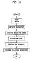
- FIG. 5is a flowchart illustrating a process for improving the resolution of an image captured in system 40 , according to a preferred embodiment of the present invention.
- an image of document 46is formed on sensor 44 of imaging system 40 (FIG. 4 ).
- a background analysis stepsignals from pixels in sensor 44 are analyzed to determine one or more regions where the image comprises mainly background color.
- the analysisis most preferably implemented by finding regions where the change in signal level from a specific color (R, G, or B) pixel to a closest-neighbor same-color pixel is relatively low, indicating that the region being imaged comprises substantially one color.
- Averagesherein termed ⁇ overscore (R b ) ⁇ , ⁇ overscore (G b ) ⁇ , and ⁇ overscore (B b ) ⁇ , of all respective R b , G b , and B b signals within such a region are calculated.
- ⁇ overscore (R n ) ⁇ , ⁇ overscore (G n ) ⁇ , and ⁇ overscore (B n ) ⁇of all respective R n , G n , and B n , signals within such a region are calculated.
- Each pixel of sensor 44images a color which is substantially background, non-background, or a combination of background and non-background, and generates a signal “x.”
- signal x and values of ⁇ Rb , ⁇ Bb , ⁇ Rn , and ⁇ Bnare used to generate an intensity and a color for each pixel.
- ⁇ B and ⁇ R for each pixelare calculated using a linear combination of ⁇ Bb ⁇ Rb ⁇ ⁇ and ⁇ ⁇ ⁇ Bn ⁇ Rn , the linear combination being a function of how x compares to averaged background and non-background values for the specific pixel. These values are then used in equations (3) and (2), as necessary, in order to find values of R, G, and B to substitute into equation (1), and so find a value of Y and C for each pixel.
- FIG. 6is a schematic diagram of a calibration grid 60 used in a process for reducing effects of lens aberrations, according to a preferred embodiment of the present invention.
- Grid 60is most preferably implemented as a set of transparent horizontal and vertical lines 62 on a substantially opaque background 64 , the lines forming a substantially square array. Lines 62 are most preferably blurred at their edges, so as to prevent, as explained in more detail below, aliasing of an image produced by grid 60 .
- Grid 60is dimensioned so that each of lines 62 forms an image more than two pixels wide on sensor 44 , when the grid is positioned as object 46 in system 40 (FIG. 4 ). To image grid 60 on the sensor, the grid is most preferably illuminated by substantially white light.
- Each color plane of sensor 44is analyzed separately, to locate vertices in the image of the grid.
- the verticesare located by detecting vertical and horizontal line crossings.
- all blue pixels generating a signal above a predetermined levelare analyzed.
- the pixelsare allocated to a specific vertical and/or a specific horizontal line structure, by determining relationships between adjacent blue pixels, or by other means known in the art.
- a first order determinationis made of a vertex as one or more adjacent blue pixels which have been allocated to both a vertical and a horizontal line structure.
- a more accurate determination of the position of the particular vertexis made by finding the point of intersection of the vertical and horizontal lines in the region of the first order vertex.
- images formed by device 42will have chromatic aberrations.
- the location of any specific vertex, as determined by equations (6) for the three color planeswill generally be displaced one from the other.
- the blue verticeswill be displaced towards the center of the image, and the red vertices will be displaced away from the center of the image, relative to the green vertices.
- correction factorsare calculated for each red vertex and each blue vertex, as described herein.
- L simultaneous equations (2)with six unknowns.
- the equationsare used to evaluate values for a 0 , a 1 , a 2 , a 3 , a 4 , and a 5 , preferably by a method of least squares fitting, or alternatively by some other standard method known in the art for solving simultaneous equations.
- the values of a 0 , a 1 , a 2 , a 3 , a 4 , and a 5are then stored in CPU 54 .
- a similar process to that described aboveis implemented in order to find corresponding correction coefficients for second-order polynomials for the vertical offset of each red vertex.
- the processis also implemented for the horizontal and vertical offsets of each blue vertex, so that a total of 24 correction coefficients are generated and stored in CPU 54 .
- These coefficientsare used, as described hereinbelow, to improve the color balance of an image formed on sensor 44 .
- FIG. 7is a schematic diagram showing an offset image 70 , according to a preferred embodiment of the present invention.
- Image 70 on a blue pixel 68is offset from the pixel because of distortions which are introduced by imaging system 40 .
- Image 70is offset horizontally by ⁇ x B and vertically by ⁇ y B .
- the signal B generated by pixel 68 , and the corresponding green value G(B) based on B, due to image 70is reduced.
- Equation (9)is generated as one possible form of a linear interpolation using signal values at pixels 72 , 74 and 68 . Equation (9) assumes that only nearest-neighbor vertical and horizontal pixels to pixel 68 have a substantial effect on signal B.
- G ⁇ ( B cor )G ⁇ ( B ) - ⁇ ⁇ ⁇ x B ⁇ ( 1 - ⁇ ⁇ ⁇ y B ) ⁇ G3 - ⁇ ⁇ ⁇ y B ⁇ ( 1 - ⁇ ⁇ ⁇ x B ) ⁇ G4 - ⁇ ⁇ ⁇ x B ⁇ ⁇ ⁇ ⁇ y B ⁇ G ⁇ ( R4 ) ( 1 - ⁇ ⁇ ⁇ x B ) ⁇ ( 1 - ⁇ ⁇ ⁇ y B ) ( 10 )
- G3, G4, and G(R4)correspond to respective signals, generated at pixels 76 , 78 , and 80 , which have been corrected according to equations (1), (2), and (3) as described above.
- Equation (10)is a linear interpolation of signal values from all nearest-neighbor pixels which receive energy because of the offset of image 70 .
- Values of ⁇ x B , ⁇ y B for pixel 70are calculated from the “blue” correction coefficients, determined as described above with reference to FIG. 6 , stored in CPU 54 .
- a similar processis applied to generate corrected signals for the other blue pixels, and for the red pixels, of sensor 44 , using the appropriate correction coefficients in each case, so as to improve overall image color balance produced by the sensor.
- the image qualityis further improved by enhancing edges of the image.
- Edgesare determined by considering gradients of specific color plane pixels. For example, if a pixel is found to be substantially in alignment with an edge, its contribution to equations (9) and (10) is enhanced. If the pixel is substantially orthogonal to the edge, its contribution to the equations is reduced. Methods for determining edges of images are well known in the art.
- FIG. 8is a schematic diagram illustrating an image which is generated to sub-pixel resolution, according to a preferred embodiment of the present invention.
- a vertical line 90having a width of 2 pixels and having a non-background color, is imaged onto sensor 44 .
- Line 90is assumed to be aligned with a vertical axis of the sensor.
- Line 90is part of an image 91 , substantially comprised of non-background and background colors.
- a pixel which completely images non-background coloris assumed to generate a signal equal to 255.
- a pixel which completely images background coloris assumed to generate a signal equal to 0.
- An ideal output from three pixels A 1 , A 2 , and A 3is shown in a graph 92 , wherein a width of pixel A 1 is W 1 , and a width of pixel A 3 is W 3 , where W 1 and W 3 are fractions of a width of a pixel in sensor 44 . It is assumed that W 1 >0.5, and that W 3 ⁇ 0.5.
- An actual output from the three pixels A 1 , A 2 , and A 3is shown in a graph 94 .
- a graph 96shows the effect of doubling the pixel resolution to sub-pixels B 1 , B 2 , . . . , B 6 .
- the signal from pixel A 1is divided into two, a first signal at sub-pixel B 2 , closest to the known non-background value of A 2 , having a value 255, and a second signal at sub-pixel B 1 having a value 2*(W 1 ⁇ 0.5)*255.
- the signal from pixel A 3is divided into two, a first signal at sub-pixel B 5 , closest to the known non-background value of A 2 , having a value 2*W 3 *255, and a second signal at sub-pixel B 6 having a value 0.
- a graph 98shows the effect of further doubling the pixel resolution to sub-pixels C 1 , C 2 , . . . , C 10 , and allocating the signal of each sub-pixel to be either 255 or 0, depending on which value is closest after the doubling process.
- sub-pixel B 1is split into a sub-pixel C 2 having a signal 255
- a sub-pixel C 1having a signal 0
- sub-pixel B 5is split into a sub-pixel C 9 having a signal 255
- a sub-pixel C 10having a signal 0 , assuming that 32 255 ⁇ W 3 ⁇ 96 255 .
- FIG. 8The process illustrated in FIG. 8 is theoretical, and has assumed that line 90 is aligned with an axis of sensor 44 .
- a line that is imaged on sensor 44will in general not be so aligned.
- imaging system 40FIG. 4
- spreads the image of each point of object 46according to a point spread function, as is known in the art (the spreading function is typically dependent on properties of imaging device 42 , such as an effective aperture of the device).
- object 46is typically not only comprised of lines such as line 90 .
- the method described hereinbelow, with reference to FIG. 9substantially resolves these limitations.
- FIG. 9is a flowchart showing a method for generating sub-pixel resolution, according to a preferred embodiment of the present invention.
- the method shown in FIG. 9implements the process described above with reference to FIG. 8 .
- an imageis formed on sensor 44 , and an image resolution improvement process, substantially as described above with reference to FIG. 5 , is performed.
- the imageis assumed to be implemented substantially from two colors, and elements of the image which are to have their resolution increased are assumed to comprise substantially linear elements.
- the imageis analyzed for single straight line segments formed from pixels having a non-background color, by methods known in the art.
- line segments foundwill not be aligned with an axis of the sensor.
- a linear transformation of pixels comprising each segment, and of pixels in the region of each respective segmentis performed.
- the transformationis performed so as to generate a set of equivalent pixel values on a grid having an axis perpendicular to the respective line.
- Such linear transformationsare well known in the art.
- Regions which have been found to comprise single straight line segmentsare then deblurred, using one of the deblurring algorithms known in the art.
- the specific deblurring algorithmgenerates deblurred pixels.
- a pixel-sized imageis offset and so overlaps more than one pixel. These pixels are analyzed more than once, according to the colors of adjacent pixels. For example, information regarding pixel G 3 can be found from G 3 itself and from the overlap of pixel B on G 3 . Those skilled in the art will be able to correlate these analyses to further increase the resolution of sensor 44 .
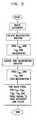
- FIG. 10is a flowchart showing a method for optical character recognition (OCR), according to a preferred embodiment of the present invention.
- OCRoptical character recognition
- OCR systemsuse a system of binarization of an image before processing the image to derive text.
- the OCR system performanceis very sensitive to the binarization process used.
- the flowchart described hereinuses gray level information and knowledge of adjacent pixel interrelationships generated by sensor 44 , together with a knowledge of the point spread function of imaging device 42 , to improve OCR.
- an image comprising textis formed on sensor 44 .
- the imageis deblurred using one of the deblurring algorithms known in the art.
- the imageis then processed substantially according to the method described hereinabove with reference to FIG. 5 , in order to improve the resolution of the image.
- the improved imageis then processed substantially according to the methods described hereinabove with reference to FIGS. 7 , 8 and 9 , to improve image color balance, and to resolve the image to sub-pixel resolution.
- the imageis binarized and subjected to an OCR process known in the art.
- the process of FIG. 5is adapted to restore delicate lines in an image.
- image 50comprises fine lines having the non-background color on the background color
- the fine linesmay be initially undetected because pixels comprising the fine lines are assumed to be part of the background.
- a later analysiscan restore the fine lines by “forcing” the color.
- the non-background colorhas been determined to be cyan, ( B + G 2 ) .
- a green pixelwhich initially does not appear to be cyan, but which has adjacent blue pixels which are cyan, may be designated as being color cyan.
- the signal of the green pixelis altered accordingly. Forcing a color to a non-background pixel (according to its relevant neighbors) helps restore the line, and also prevents color artifacts that normally characterize images of lines taken by a mosaic sensor.
- system 40is adapted to be used as facsimile machine. Most preferably, one or more of the methods described hereinabove for improving image quality of sensor 44 are implemented so as to improve the quality of fax images transmitted by the machine.
- system 40can be adapted as a business card reader, preferably comprising OCR, so that the image and/or data related to a business card can be read and stored in a database.
- system 40together with OCR, is used as a document or phrase or word translator, using automatic or semi-automatic translation methods known in the art.
- system 40is adapted for use as a barcode reader, most preferably by further implementing the sub-pixel resolution improvement described above with reference to FIG. 8 .
- system 40is used as an image data compression device.
- the object comprising textis first imaged, and the image is processed via OCR to generate text.
- the textis transmitted or stored as is, and, if appropriate, is further processed via a text compression method known in the art. If a grayscale object is found in the object, the image is preferably compressed to a binary level by one of the processes known in the art, such as dithering or half-toning.
- system 40is adapted to be able to operate either as a full-color imaging system, i.e., without implementing the resolution improvement methods described hereinabove, or as one or more of the resolution improvement systems described hereinabove.
- a document which is imagedmay be comprised of a first area having black text on a white background, and a second area having a blue line drawing on a yellow background.
- each areamay be operated on in a generally independent manner, as described hereinabove.
Landscapes
- Engineering & Computer Science (AREA)
- Multimedia (AREA)
- Physics & Mathematics (AREA)
- Signal Processing (AREA)
- General Physics & Mathematics (AREA)
- Theoretical Computer Science (AREA)
- Spectroscopy & Molecular Physics (AREA)
- Computer Vision & Pattern Recognition (AREA)
- Health & Medical Sciences (AREA)
- General Health & Medical Sciences (AREA)
- Vascular Medicine (AREA)
- Color Television Image Signal Generators (AREA)
- Color Image Communication Systems (AREA)
- Image Input (AREA)
Abstract
Description
C=F2(R, B, G1,G2), (1)
wherein R, B, G1, and G2 correspond to signals from their respective pixels, and F1 and F2 are functions.
Y=F1(R, B, G1, G2), and
C=F2(R, B, G1, G2), (1)
wherein R, B, G1, and G2 correspond to signals from pixels of
will prevail in the region. Knowledge of values of αBand αRcan be used to calculate a value of Y and C on a pixel-by-pixel basis. For example, if a specific
has a substantially constant value, herein termed αBb, and a ratio
has a substantially constant value, herein termed αRb, for signals from the background region. Similarly, in a region which is known to be predominantly non-background, ratios for red signals (Rn), green signals (Gn), and blue signals (Bn) will also be substantially constant. Thus there is a substantially constant value αBn, equal to a ratio
and a substantially constant value αRn, equal to a ratio
for signals from the non-background region.
the linear combination being a function of how x compares to averaged background and non-background values for the specific pixel. These values are then used in equations (3) and (2), as necessary, in order to find values of R, G, and B to substitute into equation (1), and so find a value of Y and C for each pixel.
ΔxR
wherein ΔxR
ΔXR
The equations are used to evaluate values for a0, a1, a2, a3, a4, and a5, preferably by a method of least squares fitting, or alternatively by some other standard method known in the art for solving simultaneous equations. The values of a0, a1, a2, a3, a4, and a5are then stored in
wherein G1, G2, and G(B) correspond to respective signals, generated at
wherein G3, G4, and G(R4) correspond to respective signals, generated at
Similarly sub-pixel B5 is split into a sub-pixel C9 having a
A green pixel which initially does not appear to be cyan, but which has adjacent blue pixels which are cyan, may be designated as being color cyan. The signal of the green pixel is altered accordingly. Forcing a color to a non-background pixel (according to its relevant neighbors) helps restore the line, and also prevents color artifacts that normally characterize images of lines taken by a mosaic sensor.
Claims (22)
Priority Applications (1)
| Application Number | Priority Date | Filing Date | Title |
|---|---|---|---|
| US09/776,377US6876763B2 (en) | 2000-02-03 | 2001-02-02 | Image resolution improvement using a color mosaic sensor |
Applications Claiming Priority (2)
| Application Number | Priority Date | Filing Date | Title |
|---|---|---|---|
| US17995400P | 2000-02-03 | 2000-02-03 | |
| US09/776,377US6876763B2 (en) | 2000-02-03 | 2001-02-02 | Image resolution improvement using a color mosaic sensor |
Publications (2)
| Publication Number | Publication Date |
|---|---|
| US20020008715A1 US20020008715A1 (en) | 2002-01-24 |
| US6876763B2true US6876763B2 (en) | 2005-04-05 |
Family
ID=22658670
Family Applications (1)
| Application Number | Title | Priority Date | Filing Date |
|---|---|---|---|
| US09/776,377Expired - Fee RelatedUS6876763B2 (en) | 2000-02-03 | 2001-02-02 | Image resolution improvement using a color mosaic sensor |
Country Status (3)
| Country | Link |
|---|---|
| US (1) | US6876763B2 (en) |
| AU (1) | AU3047801A (en) |
| WO (1) | WO2001058129A2 (en) |
Cited By (38)
| Publication number | Priority date | Publication date | Assignee | Title |
|---|---|---|---|---|
| US20050212718A1 (en)* | 2004-03-29 | 2005-09-29 | Konica Minolta Business Technologies, Inc. | Image processing apparatus and image processing program to perform image data resolution conversion |
| US20060012841A1 (en)* | 2003-03-28 | 2006-01-19 | Olympus Corporation | Image processing apparatus and image processing program |
| US20060072778A1 (en)* | 2004-09-28 | 2006-04-06 | Xerox Corporation. | Encoding invisible electronic information in a printed document |
| US20060285845A1 (en)* | 2005-06-16 | 2006-12-21 | Olympus Corporation | Image pickup apparatus |
| US20080123994A1 (en)* | 2006-08-30 | 2008-05-29 | Stephen Schultz | Mosaic Oblique Images and Methods of Making and Using Same |
| US20080131022A1 (en)* | 2006-12-01 | 2008-06-05 | Ilia Vitsnudel | Method and Apparatus for Resolution Improvement in Digital Capturing |
| US20080170785A1 (en)* | 2007-01-15 | 2008-07-17 | Microsoft Corporation | Converting Text |
| US20080204570A1 (en)* | 2007-02-15 | 2008-08-28 | Stephen Schultz | Event Multiplexer For Managing The Capture of Images |
| US20080231700A1 (en)* | 2007-02-01 | 2008-09-25 | Stephen Schultz | Computer System for Continuous Oblique Panning |
| US20080273753A1 (en)* | 2007-05-01 | 2008-11-06 | Frank Giuffrida | System for Detecting Image Abnormalities |
| US20090002574A1 (en)* | 2007-06-29 | 2009-01-01 | Samsung Electronics Co., Ltd. | Method and a system for optical design and an imaging device using an optical element with optical aberrations |
| US20090005112A1 (en)* | 2007-06-29 | 2009-01-01 | Samsung Electronics Co., Ltd. | Optical imaging system configurations for handheld devices |
| US20090096884A1 (en)* | 2002-11-08 | 2009-04-16 | Schultz Stephen L | Method and Apparatus for Capturing, Geolocating and Measuring Oblique Images |
| US20090097744A1 (en)* | 2007-10-12 | 2009-04-16 | Stephen Schultz | System and Process for Color-Balancing a Series of Oblique Images |
| US20090141020A1 (en)* | 2007-12-03 | 2009-06-04 | Freund Joseph G | Systems and methods for rapid three-dimensional modeling with real facade texture |
| US20100296693A1 (en)* | 2009-05-22 | 2010-11-25 | Thornberry Dale R | System and process for roof measurement using aerial imagery |
| US20110096083A1 (en)* | 2009-10-26 | 2011-04-28 | Stephen Schultz | Method for the automatic material classification and texture simulation for 3d models |
| US7961905B2 (en)* | 2004-09-28 | 2011-06-14 | Xerox Corporation | Encoding invisible electronic information in a printed document |
| US8477190B2 (en) | 2010-07-07 | 2013-07-02 | Pictometry International Corp. | Real-time moving platform management system |
| US8571307B2 (en) | 2010-11-16 | 2013-10-29 | Hand Held Products, Inc. | Method and system operative to process monochrome image data |
| US8588547B2 (en) | 2008-08-05 | 2013-11-19 | Pictometry International Corp. | Cut-line steering methods for forming a mosaic image of a geographical area |
| US8600158B2 (en) | 2010-11-16 | 2013-12-03 | Hand Held Products, Inc. | Method and system operative to process color image data |
| US8823732B2 (en) | 2010-12-17 | 2014-09-02 | Pictometry International Corp. | Systems and methods for processing images with edge detection and snap-to feature |
| US9183538B2 (en) | 2012-03-19 | 2015-11-10 | Pictometry International Corp. | Method and system for quick square roof reporting |
| US9262818B2 (en) | 2007-05-01 | 2016-02-16 | Pictometry International Corp. | System for detecting image abnormalities |
| US9275080B2 (en) | 2013-03-15 | 2016-03-01 | Pictometry International Corp. | System and method for early access to captured images |
| US9292913B2 (en) | 2014-01-31 | 2016-03-22 | Pictometry International Corp. | Augmented three dimensional point collection of vertical structures |
| US20170024594A1 (en)* | 2010-10-12 | 2017-01-26 | International Business Machines Corporation | Deconvolution of digital images |
| US9612598B2 (en) | 2014-01-10 | 2017-04-04 | Pictometry International Corp. | Unmanned aircraft structure evaluation system and method |
| US9753950B2 (en) | 2013-03-15 | 2017-09-05 | Pictometry International Corp. | Virtual property reporting for automatic structure detection |
| US9881163B2 (en) | 2013-03-12 | 2018-01-30 | Pictometry International Corp. | System and method for performing sensitive geo-spatial processing in non-sensitive operator environments |
| US9953112B2 (en) | 2014-02-08 | 2018-04-24 | Pictometry International Corp. | Method and system for displaying room interiors on a floor plan |
| US10325350B2 (en) | 2011-06-10 | 2019-06-18 | Pictometry International Corp. | System and method for forming a video stream containing GIS data in real-time |
| US10402676B2 (en) | 2016-02-15 | 2019-09-03 | Pictometry International Corp. | Automated system and methodology for feature extraction |
| US10502813B2 (en) | 2013-03-12 | 2019-12-10 | Pictometry International Corp. | LiDAR system producing multiple scan paths and method of making and using same |
| US10671648B2 (en) | 2016-02-22 | 2020-06-02 | Eagle View Technologies, Inc. | Integrated centralized property database systems and methods |
| US12079013B2 (en) | 2016-01-08 | 2024-09-03 | Pictometry International Corp. | Systems and methods for taking, processing, retrieving, and displaying images from unmanned aerial vehicles |
| US12332660B2 (en) | 2018-11-21 | 2025-06-17 | Eagle View Technologies, Inc. | Navigating unmanned aircraft using pitch |
Families Citing this family (10)
| Publication number | Priority date | Publication date | Assignee | Title |
|---|---|---|---|---|
| JP2005209695A (en)* | 2004-01-20 | 2005-08-04 | Toshiba Corp | Solid-state imaging device and manufacturing method thereof |
| US8036494B2 (en) | 2004-04-15 | 2011-10-11 | Hewlett-Packard Development Company, L.P. | Enhancing image resolution |
| US7728844B2 (en)* | 2004-07-09 | 2010-06-01 | Nokia Corporation | Restoration of color components in an image model |
| US7730406B2 (en) | 2004-10-20 | 2010-06-01 | Hewlett-Packard Development Company, L.P. | Image processing system and method |
| US7734092B2 (en)* | 2006-03-07 | 2010-06-08 | Ancestry.Com Operations Inc. | Multiple image input for optical character recognition processing systems and methods |
| US7907791B2 (en)* | 2006-11-27 | 2011-03-15 | Tessera International, Inc. | Processing of mosaic images |
| JP4603589B2 (en)* | 2008-02-27 | 2010-12-22 | 株式会社沖データ | Image processing device |
| US20100186234A1 (en) | 2009-01-28 | 2010-07-29 | Yehuda Binder | Electric shaver with imaging capability |
| TWI495862B (en)* | 2012-10-04 | 2015-08-11 | Pixart Imaging Inc | Method of testing image sensor and realted apparatus thereof |
| JP5701942B2 (en)* | 2013-07-10 | 2015-04-15 | オリンパス株式会社 | Imaging apparatus, camera system, and image processing method |
Citations (11)
| Publication number | Priority date | Publication date | Assignee | Title |
|---|---|---|---|---|
| WO1984002990A2 (en) | 1983-01-27 | 1984-08-02 | Hughes Aircraft Co | Resolution enhancement and zoom |
| EP0729278A2 (en) | 1995-02-27 | 1996-08-28 | SANYO ELECTRIC Co., Ltd. | 1-Chip color video camera for generating inter-pixel color signal component by interpolating primary color signals from neighboring pixels |
| JPH09168157A (en) | 1995-12-18 | 1997-06-24 | Olympus Optical Co Ltd | Color image pickup device and color image pickup element |
| US5848185A (en)* | 1994-12-28 | 1998-12-08 | Canon Kabushiki Kaisha | Image processing apparatus and method |
| WO1999024936A1 (en) | 1997-11-10 | 1999-05-20 | Gentech Corporation | System and method for generating super-resolution-enhanced mosaic images |
| US5929866A (en)* | 1996-01-25 | 1999-07-27 | Adobe Systems, Inc | Adjusting contrast in anti-aliasing |
| JPH11262022A (en) | 1998-03-10 | 1999-09-24 | Sanyo Electric Co Ltd | Single-panel color camera |
| US5969756A (en)* | 1994-06-13 | 1999-10-19 | Image Processing Systems Inc. | Test and alignment system for electronic display devices and test fixture for same |
| US6347156B1 (en)* | 1998-05-27 | 2002-02-12 | Fujitsu Limited | Device, method and storage medium for recognizing a document image |
| US6366696B1 (en)* | 1996-12-20 | 2002-04-02 | Ncr Corporation | Visual bar code recognition method |
| US6462835B1 (en)* | 1998-07-15 | 2002-10-08 | Kodak Polychrome Graphics, Llc | Imaging system and method |
Family Cites Families (6)
| Publication number | Priority date | Publication date | Assignee | Title |
|---|---|---|---|---|
| US6005560A (en)* | 1992-10-01 | 1999-12-21 | Quark, Inc. | Multi-media project management and control system |
| US5579414A (en)* | 1992-10-19 | 1996-11-26 | Fast; Bruce B. | OCR image preprocessing method for image enhancement of scanned documents by reversing invert text |
| US5588093A (en)* | 1993-12-17 | 1996-12-24 | Xerox Corporation | Color mapping to preserve detail |
| US5630037A (en)* | 1994-05-18 | 1997-05-13 | Schindler Imaging, Inc. | Method and apparatus for extracting and treating digital images for seamless compositing |
| JPH09270924A (en)* | 1996-04-03 | 1997-10-14 | Brother Ind Ltd | Image expression characteristic setting device |
| US5764383A (en)* | 1996-05-30 | 1998-06-09 | Xerox Corporation | Platenless book scanner with line buffering to compensate for image skew |
- 2001
- 2001-02-01WOPCT/IL2001/000101patent/WO2001058129A2/enactiveApplication Filing
- 2001-02-01AUAU30478/01Apatent/AU3047801A/ennot_activeAbandoned
- 2001-02-02USUS09/776,377patent/US6876763B2/ennot_activeExpired - Fee Related
Patent Citations (12)
| Publication number | Priority date | Publication date | Assignee | Title |
|---|---|---|---|---|
| WO1984002990A2 (en) | 1983-01-27 | 1984-08-02 | Hughes Aircraft Co | Resolution enhancement and zoom |
| US5969756A (en)* | 1994-06-13 | 1999-10-19 | Image Processing Systems Inc. | Test and alignment system for electronic display devices and test fixture for same |
| US5848185A (en)* | 1994-12-28 | 1998-12-08 | Canon Kabushiki Kaisha | Image processing apparatus and method |
| EP0729278A2 (en) | 1995-02-27 | 1996-08-28 | SANYO ELECTRIC Co., Ltd. | 1-Chip color video camera for generating inter-pixel color signal component by interpolating primary color signals from neighboring pixels |
| US5852468A (en)* | 1995-02-27 | 1998-12-22 | Sanyo Electric Co., Ltd. | 1-chip color video camera for generating inter-pixel color signal component by interpolating primary color signals from neighboring pixels |
| JPH09168157A (en) | 1995-12-18 | 1997-06-24 | Olympus Optical Co Ltd | Color image pickup device and color image pickup element |
| US5929866A (en)* | 1996-01-25 | 1999-07-27 | Adobe Systems, Inc | Adjusting contrast in anti-aliasing |
| US6366696B1 (en)* | 1996-12-20 | 2002-04-02 | Ncr Corporation | Visual bar code recognition method |
| WO1999024936A1 (en) | 1997-11-10 | 1999-05-20 | Gentech Corporation | System and method for generating super-resolution-enhanced mosaic images |
| JPH11262022A (en) | 1998-03-10 | 1999-09-24 | Sanyo Electric Co Ltd | Single-panel color camera |
| US6347156B1 (en)* | 1998-05-27 | 2002-02-12 | Fujitsu Limited | Device, method and storage medium for recognizing a document image |
| US6462835B1 (en)* | 1998-07-15 | 2002-10-08 | Kodak Polychrome Graphics, Llc | Imaging system and method |
Non-Patent Citations (4)
| Title |
|---|
| Banham et al., "Digital Image Restoration," IEEE Signal Processing Magazine, Mar. 1997, pp. 24-43. |
| Lee, "Review of image-blur models in a photographic system using the principles of optics," Optical Engineering, 29(5), 405-421 (1990). |
| ST, "Vision & Imaging," product description for VV5500-VV6500 Multi Format Digital Output Sensor, pp. 1-4 (Sep. 2000). |
| U.S. Provisional application No. 60/179,954 filed Feb. 3, 2000, "Use of Color Camera for Printed and Hand-written Document Imaging, Based on Resolution Improvement of any Color Mosaic Sensor". |
Cited By (118)
| Publication number | Priority date | Publication date | Assignee | Title |
|---|---|---|---|---|
| US11069077B2 (en) | 2002-11-08 | 2021-07-20 | Pictometry International Corp. | Method and apparatus for capturing, geolocating and measuring oblique images |
| US20100302243A1 (en)* | 2002-11-08 | 2010-12-02 | Schultz Stephen L | Method and apparatus for capturing geolocating and measuring oblique images |
| US7787659B2 (en) | 2002-11-08 | 2010-08-31 | Pictometry International Corp. | Method and apparatus for capturing, geolocating and measuring oblique images |
| US9811922B2 (en) | 2002-11-08 | 2017-11-07 | Pictometry International Corp. | Method and apparatus for capturing, geolocating and measuring oblique images |
| US9443305B2 (en) | 2002-11-08 | 2016-09-13 | Pictometry International Corp. | Method and apparatus for capturing, geolocating and measuring oblique images |
| US10607357B2 (en) | 2002-11-08 | 2020-03-31 | Pictometry International Corp. | Method and apparatus for capturing, geolocating and measuring oblique images |
| US7995799B2 (en) | 2002-11-08 | 2011-08-09 | Pictometry International Corporation | Method and apparatus for capturing geolocating and measuring oblique images |
| US20090096884A1 (en)* | 2002-11-08 | 2009-04-16 | Schultz Stephen L | Method and Apparatus for Capturing, Geolocating and Measuring Oblique Images |
| US20060012841A1 (en)* | 2003-03-28 | 2006-01-19 | Olympus Corporation | Image processing apparatus and image processing program |
| US7454057B2 (en)* | 2003-03-28 | 2008-11-18 | Olympus Corporation | Image processing apparatus and image processing program |
| US7430342B2 (en)* | 2004-03-29 | 2008-09-30 | Konica Minolta Business Technologies, Inc. | Image processing apparatus and image processing program to perform image data resolution conversion |
| US20050212718A1 (en)* | 2004-03-29 | 2005-09-29 | Konica Minolta Business Technologies, Inc. | Image processing apparatus and image processing program to perform image data resolution conversion |
| US7961905B2 (en)* | 2004-09-28 | 2011-06-14 | Xerox Corporation | Encoding invisible electronic information in a printed document |
| US20060072778A1 (en)* | 2004-09-28 | 2006-04-06 | Xerox Corporation. | Encoding invisible electronic information in a printed document |
| US7505680B2 (en)* | 2005-06-16 | 2009-03-17 | Olympus Corporation | Image pickup apparatus |
| US20060285845A1 (en)* | 2005-06-16 | 2006-12-21 | Olympus Corporation | Image pickup apparatus |
| US11080911B2 (en) | 2006-08-30 | 2021-08-03 | Pictometry International Corp. | Mosaic oblique images and systems and methods of making and using same |
| US9959653B2 (en) | 2006-08-30 | 2018-05-01 | Pictometry International Corporation | Mosaic oblique images and methods of making and using same |
| US9805489B2 (en) | 2006-08-30 | 2017-10-31 | Pictometry International Corp. | Mosaic oblique images and methods of making and using same |
| US10489953B2 (en) | 2006-08-30 | 2019-11-26 | Pictometry International Corp. | Mosaic oblique images and methods of making and using same |
| US20080123994A1 (en)* | 2006-08-30 | 2008-05-29 | Stephen Schultz | Mosaic Oblique Images and Methods of Making and Using Same |
| US7873238B2 (en) | 2006-08-30 | 2011-01-18 | Pictometry International Corporation | Mosaic oblique images and methods of making and using same |
| US9437029B2 (en) | 2006-08-30 | 2016-09-06 | Pictometry International Corp. | Mosaic oblique images and methods of making and using same |
| US8126284B2 (en)* | 2006-12-01 | 2012-02-28 | Broadcom Corporation | Method and apparatus for resolution improvement in digital capturing |
| US20080131022A1 (en)* | 2006-12-01 | 2008-06-05 | Ilia Vitsnudel | Method and Apparatus for Resolution Improvement in Digital Capturing |
| US8155444B2 (en)* | 2007-01-15 | 2012-04-10 | Microsoft Corporation | Image text to character information conversion |
| US20080170785A1 (en)* | 2007-01-15 | 2008-07-17 | Microsoft Corporation | Converting Text |
| US20080231700A1 (en)* | 2007-02-01 | 2008-09-25 | Stephen Schultz | Computer System for Continuous Oblique Panning |
| US8593518B2 (en) | 2007-02-01 | 2013-11-26 | Pictometry International Corp. | Computer system for continuous oblique panning |
| US8520079B2 (en) | 2007-02-15 | 2013-08-27 | Pictometry International Corp. | Event multiplexer for managing the capture of images |
| US20080204570A1 (en)* | 2007-02-15 | 2008-08-28 | Stephen Schultz | Event Multiplexer For Managing The Capture of Images |
| US9633425B2 (en) | 2007-05-01 | 2017-04-25 | Pictometry International Corp. | System for detecting image abnormalities |
| US9262818B2 (en) | 2007-05-01 | 2016-02-16 | Pictometry International Corp. | System for detecting image abnormalities |
| US11100625B2 (en) | 2007-05-01 | 2021-08-24 | Pictometry International Corp. | System for detecting image abnormalities |
| US11514564B2 (en) | 2007-05-01 | 2022-11-29 | Pictometry International Corp. | System for detecting image abnormalities |
| US10198803B2 (en) | 2007-05-01 | 2019-02-05 | Pictometry International Corp. | System for detecting image abnormalities |
| US9959609B2 (en) | 2007-05-01 | 2018-05-01 | Pictometry International Corporation | System for detecting image abnormalities |
| US20080273753A1 (en)* | 2007-05-01 | 2008-11-06 | Frank Giuffrida | System for Detecting Image Abnormalities |
| US8385672B2 (en) | 2007-05-01 | 2013-02-26 | Pictometry International Corp. | System for detecting image abnormalities |
| US10679331B2 (en) | 2007-05-01 | 2020-06-09 | Pictometry International Corp. | System for detecting image abnormalities |
| US20090005112A1 (en)* | 2007-06-29 | 2009-01-01 | Samsung Electronics Co., Ltd. | Optical imaging system configurations for handheld devices |
| US20090002574A1 (en)* | 2007-06-29 | 2009-01-01 | Samsung Electronics Co., Ltd. | Method and a system for optical design and an imaging device using an optical element with optical aberrations |
| US10580169B2 (en) | 2007-10-12 | 2020-03-03 | Pictometry International Corp. | System and process for color-balancing a series of oblique images |
| US7991226B2 (en) | 2007-10-12 | 2011-08-02 | Pictometry International Corporation | System and process for color-balancing a series of oblique images |
| US9503615B2 (en) | 2007-10-12 | 2016-11-22 | Pictometry International Corp. | System and process for color-balancing a series of oblique images |
| US11087506B2 (en) | 2007-10-12 | 2021-08-10 | Pictometry International Corp. | System and process for color-balancing a series of oblique images |
| US20090097744A1 (en)* | 2007-10-12 | 2009-04-16 | Stephen Schultz | System and Process for Color-Balancing a Series of Oblique Images |
| US8531472B2 (en) | 2007-12-03 | 2013-09-10 | Pictometry International Corp. | Systems and methods for rapid three-dimensional modeling with real façade texture |
| US9520000B2 (en) | 2007-12-03 | 2016-12-13 | Pictometry International Corp. | Systems and methods for rapid three-dimensional modeling with real facade texture |
| US9275496B2 (en) | 2007-12-03 | 2016-03-01 | Pictometry International Corp. | Systems and methods for rapid three-dimensional modeling with real facade texture |
| US10573069B2 (en) | 2007-12-03 | 2020-02-25 | Pictometry International Corp. | Systems and methods for rapid three-dimensional modeling with real facade texture |
| US9972126B2 (en) | 2007-12-03 | 2018-05-15 | Pictometry International Corp. | Systems and methods for rapid three-dimensional modeling with real facade texture |
| US10896540B2 (en) | 2007-12-03 | 2021-01-19 | Pictometry International Corp. | Systems and methods for rapid three-dimensional modeling with real façade texture |
| US9836882B2 (en) | 2007-12-03 | 2017-12-05 | Pictometry International Corp. | Systems and methods for rapid three-dimensional modeling with real facade texture |
| US10229532B2 (en) | 2007-12-03 | 2019-03-12 | Pictometry International Corporation | Systems and methods for rapid three-dimensional modeling with real facade texture |
| US11263808B2 (en) | 2007-12-03 | 2022-03-01 | Pictometry International Corp. | Systems and methods for rapid three-dimensional modeling with real façade texture |
| US20090141020A1 (en)* | 2007-12-03 | 2009-06-04 | Freund Joseph G | Systems and methods for rapid three-dimensional modeling with real facade texture |
| US10839484B2 (en) | 2008-08-05 | 2020-11-17 | Pictometry International Corp. | Cut-line steering methods for forming a mosaic image of a geographical area |
| US10424047B2 (en) | 2008-08-05 | 2019-09-24 | Pictometry International Corp. | Cut line steering methods for forming a mosaic image of a geographical area |
| US9898802B2 (en) | 2008-08-05 | 2018-02-20 | Pictometry International Corp. | Cut line steering methods for forming a mosaic image of a geographical area |
| US11551331B2 (en) | 2008-08-05 | 2023-01-10 | Pictometry International Corp. | Cut-line steering methods for forming a mosaic image of a geographical area |
| US8588547B2 (en) | 2008-08-05 | 2013-11-19 | Pictometry International Corp. | Cut-line steering methods for forming a mosaic image of a geographical area |
| US8401222B2 (en) | 2009-05-22 | 2013-03-19 | Pictometry International Corp. | System and process for roof measurement using aerial imagery |
| US9933254B2 (en) | 2009-05-22 | 2018-04-03 | Pictometry International Corp. | System and process for roof measurement using aerial imagery |
| US20100296693A1 (en)* | 2009-05-22 | 2010-11-25 | Thornberry Dale R | System and process for roof measurement using aerial imagery |
| US10198857B2 (en) | 2009-10-26 | 2019-02-05 | Pictometry International Corp. | Method for the automatic material classification and texture simulation for 3D models |
| US20110096083A1 (en)* | 2009-10-26 | 2011-04-28 | Stephen Schultz | Method for the automatic material classification and texture simulation for 3d models |
| US9959667B2 (en) | 2009-10-26 | 2018-05-01 | Pictometry International Corp. | Method for the automatic material classification and texture simulation for 3D models |
| US9330494B2 (en) | 2009-10-26 | 2016-05-03 | Pictometry International Corp. | Method for the automatic material classification and texture simulation for 3D models |
| US11483518B2 (en) | 2010-07-07 | 2022-10-25 | Pictometry International Corp. | Real-time moving platform management system |
| US8477190B2 (en) | 2010-07-07 | 2013-07-02 | Pictometry International Corp. | Real-time moving platform management system |
| US10140495B2 (en)* | 2010-10-12 | 2018-11-27 | International Business Machines Corporation | Deconvolution of digital images |
| US20170024594A1 (en)* | 2010-10-12 | 2017-01-26 | International Business Machines Corporation | Deconvolution of digital images |
| US20190042817A1 (en)* | 2010-10-12 | 2019-02-07 | International Business Machines Corporation | Deconvolution of digital images |
| US10803275B2 (en)* | 2010-10-12 | 2020-10-13 | International Business Machines Corporation | Deconvolution of digital images |
| US8571307B2 (en) | 2010-11-16 | 2013-10-29 | Hand Held Products, Inc. | Method and system operative to process monochrome image data |
| US8600158B2 (en) | 2010-11-16 | 2013-12-03 | Hand Held Products, Inc. | Method and system operative to process color image data |
| US8849019B2 (en) | 2010-11-16 | 2014-09-30 | Hand Held Products, Inc. | Method and system operative to process color image data |
| US8823732B2 (en) | 2010-12-17 | 2014-09-02 | Pictometry International Corp. | Systems and methods for processing images with edge detection and snap-to feature |
| US11003943B2 (en) | 2010-12-17 | 2021-05-11 | Pictometry International Corp. | Systems and methods for processing images with edge detection and snap-to feature |
| US10621463B2 (en) | 2010-12-17 | 2020-04-14 | Pictometry International Corp. | Systems and methods for processing images with edge detection and snap-to feature |
| US10325350B2 (en) | 2011-06-10 | 2019-06-18 | Pictometry International Corp. | System and method for forming a video stream containing GIS data in real-time |
| US10346935B2 (en) | 2012-03-19 | 2019-07-09 | Pictometry International Corp. | Medium and method for quick square roof reporting |
| US9183538B2 (en) | 2012-03-19 | 2015-11-10 | Pictometry International Corp. | Method and system for quick square roof reporting |
| US10311238B2 (en) | 2013-03-12 | 2019-06-04 | Pictometry International Corp. | System and method for performing sensitive geo-spatial processing in non-sensitive operator environments |
| US11525897B2 (en) | 2013-03-12 | 2022-12-13 | Pictometry International Corp. | LiDAR system producing multiple scan paths and method of making and using same |
| US9881163B2 (en) | 2013-03-12 | 2018-01-30 | Pictometry International Corp. | System and method for performing sensitive geo-spatial processing in non-sensitive operator environments |
| US10502813B2 (en) | 2013-03-12 | 2019-12-10 | Pictometry International Corp. | LiDAR system producing multiple scan paths and method of making and using same |
| US10311089B2 (en) | 2013-03-15 | 2019-06-04 | Pictometry International Corp. | System and method for early access to captured images |
| US9805059B2 (en) | 2013-03-15 | 2017-10-31 | Pictometry International Corp. | System and method for early access to captured images |
| US9753950B2 (en) | 2013-03-15 | 2017-09-05 | Pictometry International Corp. | Virtual property reporting for automatic structure detection |
| US9275080B2 (en) | 2013-03-15 | 2016-03-01 | Pictometry International Corp. | System and method for early access to captured images |
| US11087131B2 (en) | 2014-01-10 | 2021-08-10 | Pictometry International Corp. | Unmanned aircraft structure evaluation system and method |
| US10181081B2 (en) | 2014-01-10 | 2019-01-15 | Pictometry International Corp. | Unmanned aircraft structure evaluation system and method |
| US12123959B2 (en) | 2014-01-10 | 2024-10-22 | Pictometry International Corp. | Unmanned aircraft structure evaluation system and method |
| US11747486B2 (en) | 2014-01-10 | 2023-09-05 | Pictometry International Corp. | Unmanned aircraft structure evaluation system and method |
| US10032078B2 (en) | 2014-01-10 | 2018-07-24 | Pictometry International Corp. | Unmanned aircraft structure evaluation system and method |
| US9612598B2 (en) | 2014-01-10 | 2017-04-04 | Pictometry International Corp. | Unmanned aircraft structure evaluation system and method |
| US10037464B2 (en) | 2014-01-10 | 2018-07-31 | Pictometry International Corp. | Unmanned aircraft structure evaluation system and method |
| US10318809B2 (en) | 2014-01-10 | 2019-06-11 | Pictometry International Corp. | Unmanned aircraft structure evaluation system and method |
| US10204269B2 (en) | 2014-01-10 | 2019-02-12 | Pictometry International Corp. | Unmanned aircraft obstacle avoidance |
| US10037463B2 (en) | 2014-01-10 | 2018-07-31 | Pictometry International Corp. | Unmanned aircraft structure evaluation system and method |
| US10181080B2 (en) | 2014-01-10 | 2019-01-15 | Pictometry International Corp. | Unmanned aircraft structure evaluation system and method |
| US11120262B2 (en) | 2014-01-10 | 2021-09-14 | Pictometry International Corp. | Unmanned aircraft structure evaluation system and method |
| US10338222B2 (en) | 2014-01-31 | 2019-07-02 | Pictometry International Corp. | Augmented three dimensional point collection of vertical structures |
| US11686849B2 (en) | 2014-01-31 | 2023-06-27 | Pictometry International Corp. | Augmented three dimensional point collection of vertical structures |
| US9542738B2 (en) | 2014-01-31 | 2017-01-10 | Pictometry International Corp. | Augmented three dimensional point collection of vertical structures |
| US10942276B2 (en) | 2014-01-31 | 2021-03-09 | Pictometry International Corp. | Augmented three dimensional point collection of vertical structures |
| US10571575B2 (en) | 2014-01-31 | 2020-02-25 | Pictometry International Corp. | Augmented three dimensional point collection of vertical structures |
| US9292913B2 (en) | 2014-01-31 | 2016-03-22 | Pictometry International Corp. | Augmented three dimensional point collection of vertical structures |
| US11100259B2 (en) | 2014-02-08 | 2021-08-24 | Pictometry International Corp. | Method and system for displaying room interiors on a floor plan |
| US9953112B2 (en) | 2014-02-08 | 2018-04-24 | Pictometry International Corp. | Method and system for displaying room interiors on a floor plan |
| US12079013B2 (en) | 2016-01-08 | 2024-09-03 | Pictometry International Corp. | Systems and methods for taking, processing, retrieving, and displaying images from unmanned aerial vehicles |
| US11417081B2 (en) | 2016-02-15 | 2022-08-16 | Pictometry International Corp. | Automated system and methodology for feature extraction |
| US10402676B2 (en) | 2016-02-15 | 2019-09-03 | Pictometry International Corp. | Automated system and methodology for feature extraction |
| US10796189B2 (en) | 2016-02-15 | 2020-10-06 | Pictometry International Corp. | Automated system and methodology for feature extraction |
| US10671648B2 (en) | 2016-02-22 | 2020-06-02 | Eagle View Technologies, Inc. | Integrated centralized property database systems and methods |
| US12332660B2 (en) | 2018-11-21 | 2025-06-17 | Eagle View Technologies, Inc. | Navigating unmanned aircraft using pitch |
Also Published As
| Publication number | Publication date |
|---|---|
| WO2001058129A3 (en) | 2002-05-16 |
| US20020008715A1 (en) | 2002-01-24 |
| AU3047801A (en) | 2001-08-14 |
| WO2001058129A2 (en) | 2001-08-09 |
Similar Documents
| Publication | Publication Date | Title |
|---|---|---|
| US6876763B2 (en) | Image resolution improvement using a color mosaic sensor | |
| US8189075B2 (en) | Image processing apparatus and image processing method for generating second image data by interpolating color components of pixels in first image data | |
| US7580070B2 (en) | System and method for roll-off correction in image processing | |
| US6701009B1 (en) | Method of separated color foreground and background pixel improvement | |
| JP4668185B2 (en) | Image processing method | |
| US8786709B2 (en) | Methods and apparatuses for addressing chromatic aberrations and purple fringing | |
| US7986352B2 (en) | Image generation system including a plurality of light receiving elements and for correcting image data using a spatial high frequency component, image generation method for correcting image data using a spatial high frequency component, and computer-readable recording medium having a program for performing the same | |
| CN101778203B (en) | Image processing device | |
| US7683948B2 (en) | System and method for bad pixel replacement in image processing | |
| US8040558B2 (en) | Apparatus and method for shift invariant differential (SID) image data interpolation in fully populated shift invariant matrix | |
| US8358835B2 (en) | Method for detecting and correcting chromatic aberration, and apparatus and method for processing image using the same | |
| WO2009095422A2 (en) | Methods and apparatuses for addressing chromatic aberrations and purple fringing | |
| CN102984527A (en) | Image processing apparatus, image processing method, information recording medium, and program | |
| JP3233601B2 (en) | Image processing device | |
| CN101534375A (en) | Method for correcting chromatic aberration | |
| US8213710B2 (en) | Apparatus and method for shift invariant differential (SID) image data interpolation in non-fully populated shift invariant matrix | |
| US20020141003A1 (en) | Method of three dimensional color vector determinant for automatic kanji and chinese character detection and enhancement | |
| US7656441B2 (en) | Hue correction for electronic imagers | |
| JP2003134523A (en) | Image pickup apparatus and method | |
| JPH07264406A (en) | Gamma correction method for image reader | |
| KR960002694B1 (en) | Color image reading correction device | |
| JPH0449773A (en) | Color reading device | |
| JP2003198839A (en) | Character edge detection device |
Legal Events
| Date | Code | Title | Description |
|---|---|---|---|
| AS | Assignment | Owner name:ALST TECHNICAL EXCELLENCE CENTER, ISRAEL Free format text:ASSIGNMENT OF ASSIGNORS INTEREST;ASSIGNORS:SOREK, NOAM;VITSNUDEL, IIIA;FRIDENTAL, RON;REEL/FRAME:011711/0153 Effective date:20010321 | |
| CC | Certificate of correction | ||
| FEPP | Fee payment procedure | Free format text:PAYOR NUMBER ASSIGNED (ORIGINAL EVENT CODE: ASPN); ENTITY STATUS OF PATENT OWNER: LARGE ENTITY | |
| AS | Assignment | Owner name:VITSNUDEL, ILIA, ISRAEL Free format text:COURT ORDER;ASSIGNOR:ALST TECHNICAL EXCELLENCE CENTER;REEL/FRAME:020723/0323 Effective date:20080221 Owner name:SOREK, NOAM, ISRAEL Free format text:COURT ORDER;ASSIGNOR:ALST TECHNICAL EXCELLENCE CENTER;REEL/FRAME:020723/0323 Effective date:20080221 Owner name:FRIDENTAL, RON, ISRAEL Free format text:COURT ORDER;ASSIGNOR:ALST TECHNICAL EXCELLENCE CENTER;REEL/FRAME:020723/0323 Effective date:20080221 | |
| AS | Assignment | Owner name:SIGHTIC VISTA LTD., ISRAEL Free format text:ASSIGNMENT OF ASSIGNORS INTEREST;ASSIGNORS:SOREK, NOAM;FRIDENTAL, RON;VITSNUDEL, ILIA;REEL/FRAME:020762/0153;SIGNING DATES FROM 20080404 TO 20080405 | |
| FPAY | Fee payment | Year of fee payment:4 | |
| AS | Assignment | Owner name:BROADCOM CORPORATION, CALIFORNIA Free format text:ASSIGNMENT OF ASSIGNORS INTEREST;ASSIGNOR:SIGHTIC VISTA, LTD.;REEL/FRAME:026836/0013 Effective date:20110101 | |
| REMI | Maintenance fee reminder mailed | ||
| FEPP | Fee payment procedure | Free format text:PAT HOLDER NO LONGER CLAIMS SMALL ENTITY STATUS, ENTITY STATUS SET TO UNDISCOUNTED (ORIGINAL EVENT CODE: STOL); ENTITY STATUS OF PATENT OWNER: LARGE ENTITY | |
| FPAY | Fee payment | Year of fee payment:8 | |
| SULP | Surcharge for late payment | Year of fee payment:7 | |
| AS | Assignment | Owner name:BANK OF AMERICA, N.A., AS COLLATERAL AGENT, NORTH CAROLINA Free format text:PATENT SECURITY AGREEMENT;ASSIGNOR:BROADCOM CORPORATION;REEL/FRAME:037806/0001 Effective date:20160201 Owner name:BANK OF AMERICA, N.A., AS COLLATERAL AGENT, NORTH Free format text:PATENT SECURITY AGREEMENT;ASSIGNOR:BROADCOM CORPORATION;REEL/FRAME:037806/0001 Effective date:20160201 | |
| REMI | Maintenance fee reminder mailed | ||
| AS | Assignment | Owner name:AVAGO TECHNOLOGIES GENERAL IP (SINGAPORE) PTE. LTD., SINGAPORE Free format text:ASSIGNMENT OF ASSIGNORS INTEREST;ASSIGNOR:BROADCOM CORPORATION;REEL/FRAME:041706/0001 Effective date:20170120 Owner name:AVAGO TECHNOLOGIES GENERAL IP (SINGAPORE) PTE. LTD Free format text:ASSIGNMENT OF ASSIGNORS INTEREST;ASSIGNOR:BROADCOM CORPORATION;REEL/FRAME:041706/0001 Effective date:20170120 | |
| AS | Assignment | Owner name:BROADCOM CORPORATION, CALIFORNIA Free format text:TERMINATION AND RELEASE OF SECURITY INTEREST IN PATENTS;ASSIGNOR:BANK OF AMERICA, N.A., AS COLLATERAL AGENT;REEL/FRAME:041712/0001 Effective date:20170119 | |
| LAPS | Lapse for failure to pay maintenance fees | ||
| STCH | Information on status: patent discontinuation | Free format text:PATENT EXPIRED DUE TO NONPAYMENT OF MAINTENANCE FEES UNDER 37 CFR 1.362 | |
| FP | Lapsed due to failure to pay maintenance fee | Effective date:20170405 |