US6876623B1 - Tuning scheme for code division multiplex broadcasting system - Google Patents
Tuning scheme for code division multiplex broadcasting systemDownload PDFInfo
- Publication number
- US6876623B1 US6876623B1US09/250,743US25074399AUS6876623B1US 6876623 B1US6876623 B1US 6876623B1US 25074399 AUS25074399 AUS 25074399AUS 6876623 B1US6876623 B1US 6876623B1
- Authority
- US
- United States
- Prior art keywords
- signal
- satellite
- interleaved
- interleaver
- tuning
- Prior art date
- Legal status (The legal status is an assumption and is not a legal conclusion. Google has not performed a legal analysis and makes no representation as to the accuracy of the status listed.)
- Expired - Lifetime
Links
- 230000003111delayed effectEffects0.000claimsabstractdescription53
- 239000012792core layerSubstances0.000claimsabstractdescription41
- 239000010410layerSubstances0.000claimsabstractdescription33
- 238000000034methodMethods0.000claimsdescription52
- 230000001934delayEffects0.000claimsdescription5
- 230000005540biological transmissionEffects0.000abstractdescription31
- 238000012937correctionMethods0.000abstractdescription10
- 238000005562fadingMethods0.000abstractdescription7
- 238000005516engineering processMethods0.000abstractdescription6
- 238000001228spectrumMethods0.000description4
- 230000007480spreadingEffects0.000description4
- 238000004891communicationMethods0.000description3
- 230000001427coherent effectEffects0.000description2
- 239000002131composite materialSubstances0.000description2
- 238000007796conventional methodMethods0.000description2
- 238000001514detection methodMethods0.000description2
- 230000003044adaptive effectEffects0.000description1
- 239000000654additiveSubstances0.000description1
- 230000000996additive effectEffects0.000description1
- 238000013459approachMethods0.000description1
- 230000003139buffering effectEffects0.000description1
- 230000008859changeEffects0.000description1
- 230000009977dual effectEffects0.000description1
- 230000000694effectsEffects0.000description1
- 230000003631expected effectEffects0.000description1
- 230000002349favourable effectEffects0.000description1
- 238000001914filtrationMethods0.000description1
- 230000002452interceptive effectEffects0.000description1
- 238000012986modificationMethods0.000description1
- 230000004048modificationEffects0.000description1
- 238000012545processingMethods0.000description1
- 238000011084recoveryMethods0.000description1
- 230000004044responseEffects0.000description1
- 238000007493shaping processMethods0.000description1
Images


Classifications
- H—ELECTRICITY
- H04—ELECTRIC COMMUNICATION TECHNIQUE
- H04N—PICTORIAL COMMUNICATION, e.g. TELEVISION
- H04N7/00—Television systems
- H04N7/20—Adaptations for transmission via a GHz frequency band, e.g. via satellite
- H—ELECTRICITY
- H04—ELECTRIC COMMUNICATION TECHNIQUE
- H04B—TRANSMISSION
- H04B7/00—Radio transmission systems, i.e. using radiation field
- H04B7/14—Relay systems
- H04B7/15—Active relay systems
- H04B7/185—Space-based or airborne stations; Stations for satellite systems
- H04B7/18523—Satellite systems for providing broadcast service to terrestrial stations, i.e. broadcast satellite service
- H—ELECTRICITY
- H04—ELECTRIC COMMUNICATION TECHNIQUE
- H04H—BROADCAST COMMUNICATION
- H04H20/00—Arrangements for broadcast or for distribution combined with broadcast
- H04H20/20—Arrangements for broadcast or distribution of identical information via plural systems
- H04H20/22—Arrangements for broadcast of identical information via plural broadcast systems
- H—ELECTRICITY
- H04—ELECTRIC COMMUNICATION TECHNIQUE
- H04H—BROADCAST COMMUNICATION
- H04H20/00—Arrangements for broadcast or for distribution combined with broadcast
- H04H20/65—Arrangements characterised by transmission systems for broadcast
- H04H20/71—Wireless systems
- H04H20/74—Wireless systems of satellite networks
- H—ELECTRICITY
- H04—ELECTRIC COMMUNICATION TECHNIQUE
- H04L—TRANSMISSION OF DIGITAL INFORMATION, e.g. TELEGRAPHIC COMMUNICATION
- H04L1/00—Arrangements for detecting or preventing errors in the information received
- H04L1/004—Arrangements for detecting or preventing errors in the information received by using forward error control
- H04L1/0056—Systems characterized by the type of code used
- H04L1/0057—Block codes
- H—ELECTRICITY
- H04—ELECTRIC COMMUNICATION TECHNIQUE
- H04L—TRANSMISSION OF DIGITAL INFORMATION, e.g. TELEGRAPHIC COMMUNICATION
- H04L1/00—Arrangements for detecting or preventing errors in the information received
- H04L1/004—Arrangements for detecting or preventing errors in the information received by using forward error control
- H04L1/0056—Systems characterized by the type of code used
- H04L1/0071—Use of interleaving
Definitions
- the present inventionrelates generally to satellite broadcasting techniques, and more particularly, to satellite broadcasting techniques based on Code Division Multiple Access (CDMA) technology.
- CDMACode Division Multiple Access
- Satellite broadcasting systems for transmitting programming contenthave become increasingly popular in many parts of the world.
- Direct Broadcasting Satellite (DBS) systemstransmit television programming content, for example, to a geo-synchronous satellite, which broadcasts the content back to the customers.
- the transmitted programmingcan be received by anyone with an appropriate receiver, such as an antenna or a satellite dish.
- Satellite broadcasting systemshave been proposed or suggested for broadcasting audio programming content from geo-synchronous satellites to customers in a large coverage area, such as the continental United States. Satellite broadcasting systems for television and radio content provide potentially national coverage areas, and thus improve over conventional terrestrial television stations and AM/FM radio stations that provide only regional coverage.
- Code Division Multiple Access techniqueshave been proposed for satellite broadcasting systems to permit a number of programming channels to be transmitted on the same carrier frequency. Code Division Multiple Access techniques transmit multiple information signals on the same carrier frequency, and differentiate each programming channel by encoding the channel with a unique orthogonal code.
- CD Radio Incorporatedhas proposed a satellite broadcasting system having two satellites and a group of repeaters to provide audio service.
- the CD Radio systemis described, for example, in U.S. Pat. Nos. 5,278,863, 5,319,673, 5,485,485 and 5,592,471.
- LOSdirect line of sight
- many satellite broadcasting systemstransmit a delayed version of each program channel with the on-time version of the program channel to permit uninterrupted reception in the event of a blockage.
- U.S. patent application Ser. No. 09/220,722, filed Dec. 24, 1998, a parent application to the present patent applicationdiscloses a code division multiplex (CDM) satellite broadcasting systems that transmits both the on-time and delayed versions of each program channel transmitted from the same satellite.
- CDDMcode division multiplex
- forward error correction schemessuch as convolutional and block coding
- Forward error correction schemesprotect the transmitted signals so that even if part of a signal is received with error, the error may be corrected or minimized using other transmitted information that is received under more favorable conditions.
- Convolutional codeseffectively reduce reception errors due to relatively slow fading, provided appropriate interleaving is also employed. Interleaving scrambles a signal over a certain time interval. In order for convolutional codes to work properly, consecutive symbols presented to a signal channel decoder at the receiver should be uncorrelated. For example, the consecutive symbols should be separated timewise from one another during transmission, such as occurs by interleaving.
- a parent application to the present patent applicationdiscloses a technique that allows a receiver to reproduce a program source with minimal delay when the receiver is first tuned to the program source.
- a tuning channelis provided for each program channel that utilizes a shorter interleaver length than the corresponding primary program channel.
- a CDM satellite transmission systemthat broadcasts programming content, such as audio and video information, using one or more geo-synchronous satellites based on Code Division Multiple Access technology.
- the CDM satellite transmission systemmay optionally include one or more terrestrial repeaters.
- the CDM satellite transmission systemutilizes forward error correction coding and interleaving prior to broadcasting the signals over the CDM channel.
- a mobile receiverde-interleaves the received signals over a corresponding interval, and applies the de-interleaved signal to a channel decoder.
- the CDM satellite transmission systemprovides a tuning channel corresponding to each program channel that reduces the delay when a mobile receiver is first tuned to a selected program channel.
- the tuning channelutilizes a shorter interleaver length, if any, than the corresponding primary program channel.
- a “tuning channel”is a channel that transmits at least a portion of the corresponding primary program channel using a shorter interleaver delay, if any, than the corresponding primary program channel.
- the present inventionimproves on conventional techniques that require a mobile receiver to wait for a period corresponding to the interleaver length before the receiver can decode a received signal, resulting in a delay equal to at least the interleaver length each time a new program is selected, before the new program can be reproduced.
- the CDM satellite transmission systemtransmits a four (4) second delayed version of a program signal with the on-time version of the audio output to accommodate uninterrupted reception in the event of such a blockage.
- the on-time and delayed signalsattempt to provide time diversity over a period longer than the period in which the received signal is lost.
- the on-time version of the audio outputis transmitted by a first satellite, while delayed version of the audio output is transmitted by a second satellite.
- the core layer, C(n), of a scalable audio coding schemeis utilized as the tuning channel. While the core layer, C(n), is independently decodable, the enhancement layers, E(n), provide a higher quality reproduction when decoded. Thus, a “core” reproduction of the program may be readily reproduced for purposes of tuning and program selection by a user of the CDM satellite transmission system.
- the core layer, C 2 (n), of the delayed version of the audio outputis used as the tuning channel. While the core layer, C 1 (n), and enhancement layers, E 1 (n), of the on-time signal and the enhancement layers, E 2 (n), of the delayed-time signal employ a block interleaver having a duration of four seconds, the core layer, C 2 (n), of the delayed-time signal, which is the tuning channel, employs a block interleaver having a duration of 500 milliseconds.
- FIG. 1illustrates a CDM satellite transmission system in accordance with the present invention
- FIG. 2illustrates the transmission times for the on-time and delayed signal paths for a conventional CDM satellite transmission system
- FIG. 3illustrates the transmission times for the on-time and delayed signal paths with a tuning channel in accordance with the present invention
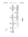
- FIG. 4illustrates the transmitter of FIG. 1 ;
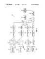
- FIG. 5illustrates a parallel implementation of the transmitter section of FIG. 4 ;
- FIG. 6illustrates a serial implementation of the transmitter section of FIG. 4 ;
- FIG. 7illustrates a parallel implementation of the receiver of FIG. 1 ;
- FIG. 8illustrates a serial implementation of the receiver of FIG. 1 .
- FIG. 1illustrates a CDM satellite transmission system 100 in accordance with the present invention.
- the CDM satellite transmission system 100transmits digital music and other audio information from an uplink station (not shown) to one or more mobile receivers, such as the mobile receiver 150 .
- a plurality of audio channelsare multiplexed onto a carrier frequency using Code Division Multiple Access technology.
- Code Division Multiplexingis used herein, since the satellite transmission system 100 operates in a broadcast mode.
- a maximum bit error rate of 10 ⁇ 5is generally desirable for compact disk quality music.
- the illustrative CDM satellite transmission system 100includes two satellites 110 , 120 operating in a broadcast mode.
- the satellites 110 , 120are designed to be geo-synchronous, and are located over a desired geographical coverage area, such as over the eastern and western United States, at appropriate angles of elevation, as dictated by the requirements of a geo-synchronous system.
- the illustrative CDM satellite transmission system 100optionally includes a plurality of terrestrial repeaters, such as the terrestrial repeater 140 , discussed below, that will operate in dense urban areas, where the direct line of sight between the satellites 110 , 120 and the mobile receiver 150 , can be blocked due to the angle of elevation and shadowing by tall buildings.
- each repeater 140 and at least one satellite 110 , 120is designed to be line of sight.
- the terrestrial repeaters 140retrieve the information from the satellite, or directly from the studio, by well-known technical means, such as wireline or microwave links. It is noted, however, that the present invention can be implemented in a CDM satellite transmission system 100 that includes only a single satellite, such as the satellite 120 , as would be apparent to a person of ordinary skill in the art.
- the direct line of sight between the mobile receiver 150 and one or both satellites 110 , 120 and the repeater 140 in the illustrative embodimentcan be blocked by underpasses or other structures. It has been observed that blockages will generally not last longer than one or two seconds.
- the CDM satellite transmission system 100may transmit a four (4) second delayed version of the signal with the on-time version of the audio output to accommodate uninterrupted reception in the event of such a blockage.
- the on-time and delayed signalsattempt to provide time diversity over a period longer than the period in which the received signal is lost.
- the receiverdecodes and combines both the on-time and delayed channels.
- one satellitesuch as satellite 110
- the other satellitesuch as satellite 120
- the CDM satellite transmission system 100utilizes forward error correction coding and interleaving prior to broadcasting the on-time and delayed signals over the CDM channel.
- the mobile receiver 150de-interleaves the received signals over a corresponding interval, and applies the de-interleaved signal to a channel decoder. Interleaving both the on-time and delayed signals accounts for short-term fades.
- the mobile receiver 150must wait for a corresponding four seconds for the de-interleaver to output de-interleaved symbols before the mobile receiver 150 can decode them.
- the four second de-interleavermust be filled before decoding can begin.
- the usermust wait at least four seconds each time a new program is selected, before the new program is reproduced.
- the CDM satellite transmission system 100provides a tuning channel for each program channel that reduces the delay when a mobile receiver 150 is first tuned to the program channel.
- the tuning channelutilizes a shorter interleaver length, if any, than the corresponding primary program channel.
- a “tuning channel”is a channel that transmits at least a portion of the corresponding primary program channel using a shorter interleaver delay, if any, than the corresponding primary program channel.
- the satellites 110 , 120receive the broadcast signal from a studio, for example, over a robust radio frequency (RF) link, and the satellites 110 , 120 will broadcast the signal after down-converting the signal to the carrier frequency.
- the terrestrial repeaters 140retrieve the information from the satellite, or directly from the studio, by well-known technical means, such as wireline or microwave links.
- the satellites 110 , 120 and the terrestrial repeaters 140broadcast the signal using the same or similar transmitter 400 , discussed below in conjunction with FIG. 4 , and multiplexing technology.
- a representative scalable audio coding schemeis described in J. Herra et al., “The Integrated Filterbank Based Scalable MPEG-4 Audio Coder,” 105 th Audio Engineering Society (AES) Convention (September 1998), incorporated by reference herein.
- a core layer, C(n)there is a core layer, C(n), and one or more enhancement layers, E(n). While the core layer, C(n), is independently decodable, the enhancement layers, E(n), provide a higher quality reproduction when decoded.
- the core layer, C(n)is used as the tuning channel.
- the audio coder rateis assumed to be 96 kilo-bits-per-second, with 32 kilo-bits-per-second allocated to the core layer, C(n), and 64 kilo-bits-per-second allocated to the enhancement layer.
- FIG. 2illustrates the transmission times for the on-time and delayed signal paths.
- the signalconsists of four second blocks of data, with C(n) and E(n) representing the channel coded core and enhancement layer data at the n-th four second block.
- the signal 210corresponds to the core and enhancement layer blocks before the interleaver stage.
- the signal 220corresponds to the interleaved on-time signal and the signal 230 corresponds to the interleaved delayed-time signal. It is noted that the on-time signal 220 and the delayed signal 230 can each be transmitted by one or both satellites 110 , 120 , as would be apparent to a person of ordinary skill in the art.
- one satellitesuch as satellite 110 transmits the on-time version of the audio output 220
- the other satellitesuch as satellite 120 transmits the delayed version of the audio output 230
- the core layer, C 2 (n), of the delayed version of the audio output 230is used as the tuning channel.
- the core layer, C 1 (n), and enhancement layers, E 1 (n), of the on-time signal 220 and the enhancement layers, E 2 (n), of the delayed-time signal 230employ a block interleaver having a duration of four seconds.
- the core layer, C 2 (n), of the delayed-time signal 230which is the tuning channel, employs a block interleaver having a duration of 500 milliseconds.
- the on-time signal 220 , C 1 (n) and E 1 , (n),is obtained by interleaving C(n) and E(n) over a four second period and is transmitted during the time period ⁇ 4n+4, 4n+8 ⁇ .
- the delayed signal 230 , C 2 (n) and E 2 (n)is obtained by interleaving C(n) and E(n) over a four second period and is transmitted during the time period ⁇ 4n+8, 4n+12 ⁇ .
- the de-interleaved output from the delayed-time signal path corresponding to C 2 (n) and E 2 (n)is combined with the de-interleaved output from the on-time signal path corresponding to C 1 (n) and E 1 (n). It is noted that C 1 (n) and E 1 (n) are the on-time components and the de-interleaved output from them are available at a time equal to ⁇ 4n+8 ⁇ . This combined signal is then fed to the channel decoders for the core and enhancement layers.
- the illustrative interleavers used to generate the signals 220 , 230 of FIG. 2are four seconds long.
- the de-interleaving delay at the receiveris at least four seconds.
- the receiverhas to buffer incoming data for at least four seconds which gives rise to a minimum tuning delay of four seconds. For example, if a user changes the audio channel at a time of ⁇ 4n+9 ⁇ (FIG. 2 ), the received data corresponding to the new channel cannot be used in the interval ⁇ 4n+9, 4n+12 ⁇ .
- C 1 (n+2) and E 1 (n+2) from the on-time path and C 2 (n+1) and E 2 (n+1) from the delayed-time pathare stored in the receiver.
- the delayed time signal C 2 (n+1) and E 2 (n+1)can be decoded and played at the audio output. It is noted that the combined signal from both on-time and delayed time paths will be available only at a time equal to ⁇ 4n+20 ⁇ .
- a channel changewas request at a time of ⁇ 4n+9 ⁇ , a signal can be provided using conventional methods only at a time equal to ⁇ 4n+16 ⁇ .
- FIG. 3illustrates the interleaving scheme with a tuning channel in accordance with the present invention.
- the signal 310corresponds to the core and enhancement layer blocks before the interleaver stage.
- the signal 320corresponds to the interleaved on-time signal and the signal 330 corresponds to the interleaved delayed-time signal. Since only the core layer, C 2 (n), of the delayed version of the audio output 330 is used as the tuning channel in the illustrative embodiment, the on-time signal 320 is the same as with the conventional interleaving scheme of FIG. 2 .
- the core layer, C 2 (n), of the delayed version of the audio output 330is interleaved over a shorter interleaver delay, such as 500 milliseconds, rather than the four second interleaver delay used for the primary channels.
- C i (n)denotes the block of channel coded core layer data in the time interval ⁇ 4n+0.5(i ⁇ 1), 4n+0.5i ⁇ , where i is an integer between one and eight.
- the on-time components, C 1 (n) and E 1 (n), and E 2 (n) from the delayed pathare available at the receiver.
- the enhancement layers, E 1 (n) and E 2 (n)can be combined and applied to the channel decoder.
- the corresponding core layer data, C 2 (n) from the delayed time path 330will be available only in the following four second duration.
- C i 2 (n)is de-interleaved and combined with the data stream corresponding to C i 1 (n) from the on-time path 320 and this combined signal is applied to the channel decoder for the core layer data.
- the tuning channelcontains only the core layer data.
- the receiverbegins buffering C 1 (n+2), E 1 (n+2) and E 2 (n+1).
- the tuning channel datais the only available decoded data until a time equal to ⁇ 4n+16 ⁇ .
- the present inventionprovides an effective tuning channel with the tuning delay varying from 500 milliseconds to one second.
- each transmitter 400includes n+1 sources 410 - 0 through 410 -n for providing n information channels.
- the zero-th channelis reserved for the pilot signal in the illustrative embodiment.
- the pilot channelallows a mobile station to acquire the timing of the Forward CDM Channel after a mobile receiver 150 is initially turned on (“initial pilot detection”).
- the pilot channelenhances the overall signal quality by providing a phase reference for coherent demodulation (“continuous pilot detection”).
- the pilot channelis unmodulated, all 1's and is assigned the orthogonal code “0” which is also the one sequence, in accordance with IS-95.
- the pilot signalis encoded with an orthogonal code 430 .
- the length of the orthogonal code 430may be determined based on the number of on-time and delayed channels to be transmitted.
- the length of the orthogonal code 430need not be a power of two.
- each information source 410 - 1 through 410 -nis encoded using a perceptual audio coder (PAC), such as those described in U.S. Pat. No. 5,732,189, assigned to the assignee of the present invention and incorporated by reference herein.
- PACperceptual audio coder
- the audio coders 410 - 1 through 410 -noutput digital information at 96 kilo-bits-per-second.
- each audio channelis processed by a corresponding transmitter section 500 , such as the transmitter section 500 -i, corresponding to the i-th branch of the transmitter 400 .
- the transmitter section 500is discussed below in conjunction with FIG. 5 .
- each transmitter section 500The spread signal outputs of each transmitter section 500 are summed by a signal summer 460 , before psuedo-noise spreading 470 is performed in quadrature and in-phase (IQ).
- Waveform shapingis performed at stage 480 using 12.5 MHz of bandwidth in the illustrative embodiment, with appropriate Nyquist rolloff, before the signals are converted to the carrier frequency, F C , and transmitted at stage 490 . It is noted that if some of the channels are known to contain only speech, then the human voice activity factor can be utilized to lower the power level of the speech channels, and increase the CDM link capacity.
- FIG. 5A parallel implementation of a transmitter section 500 is shown in FIG. 5 .
- the core layer, C 2 (n), of the delayed version of the audio output 230is used as the tuning channel in the illustrative embodiment.
- the transmitter section 500includes a primary path for encoding and transmitting the primary program channel and a tuning channel
- the tuning channelmay be disabled for the transmitted associated with the on-time version of the audio output 220 .
- the transmitter section 500includes an audio coder 510 , which may be, for example, the scalable audio coding scheme described by J. Herra et al. and incorporated above.
- the transmitter section 500includes a delay stage 515 that is configured to introduce a delay of T 1 . If the transmitter section 500 is producing the delayed version of the program source, (satellite 120 in the illustrative embodiment) the value of T 1 is set to four (4) seconds. If the transmitter section 500 is producing the on-time version of the program source, (satellite 110 in the illustrative embodiment) the value of T 1 is set to zero.
- the audio coded signalis applied to an input of a forward error correction (FEC) encoder 520 that applies, for example, a known rate 1 ⁇ 2 convolutional block code to allow recovery of bits or symbols that may be lost due to noise bursts.
- FECforward error correction
- the output of the FEC encoder 520will be 192 kilo-bits-per-second.
- the coded signal output by the forward error correction encoder 520is applied to an input of a first interleaver 530 on the primary channel.
- the first interleaver 530is configured to scramble consecutive signal bits or symbols of the coded signal stream over a first delay interval or length, D 1 , to overcome expected effects of signal fading when the signals are broadcast over a given transmission channel.
- D 1is four (4) seconds for both satellites 110 , 120 .
- the signal produced by the first interleaver 530is then encoded with an orthogonal spreading code and modulated at stage 560 .
- the length of the orthogonal codesneed not be a power of two.
- the coded signal output by the forward error correction encoder 520is also applied to an input of a second interleaver 540 on the tuning channel.
- a second forward error correction encoder 525may be optionally utilized in an alternate implementation to provide a different error correction scheme for the tuning channel.
- the second interleaver 540 on the tuning channelhas a second delay interval or interleaver length, D 2 , that is shorter than that of the first interleaver 530 on the primary channel.
- D 2second delay interval or interleaver length
- the transmitter section 500is producing the on-time version of the program source, and thus does not include a tuning channel (satellite 110 in the illustrative embodiment) the value of D 2 is set to four (4) seconds (transmitting the core layer with an interleaver length of four seconds).
- Signals output from the second interleaver 540are input to a signal delay stage 550 .
- the delay stage 550is configured to introduce a time delay, T 2 , to the tuning channel that is substantially equal to the length of the first interleaver 530 .
- T 2time delay
- the delay introduced by the delay stage 550 if the transmitter section 500 is transmitting the tuning channel (satellite 120 )is approximately 7.5 seconds (4 seconds minus 500 milliseconds to synchronize plus four second offset from enhancement layer).
- the value of T 2 if the transmitter section 500 is transmitting the on-time signal (satellite 110 )is zero.
- the tuning channelfacilitates reproduction of the program source at the receiver when the CDM satellite transmission system 100 is first tuned to the program source.
- the delayed signal produced by the second interleaver 540is then encoded with an orthogonal spreading code and modulated at stage 590 .
- the interleaved, coded 64 Kbps core layer, C 2 (n), of the delayed version of the audio output 230is used as the tuning channel
- the spreader and modulator stage 590encodes with a data rate of 64 Kbps.
- the parallel transmitter section shown in FIG. 5a plurality of spreader and modulator stages 560 -n are utilized on the primary channel.
- the interleaved, coded signal that is generated by the interleaver 530has a rate of 128 kilo-bits-per-second allocated to the enhancement layer.
- the parallel transmitter shown in FIG. 5includes two spreader and modulator stages 560 - 1 and 560 - 2 , that each encode with a data rate of 64 Kbps.
- each of the spreader and modulator stages 560 -nare associated with the enhancement layer. It is noted that the 64 Kbps of coded data for the core layer is transmitted on the tuning channel: using a four second interleaver for the on-time signal and a 500 millisecond interleaver for the delayed signal. In this manner, each of the spreader and modulator stages 560 -n for the primary channel and the spreader and modulator stage 590 for the tuning channel have the same length.
- FIG. 6A serial implementation of a transmitter section 500 ′ is shown in FIG. 6 .
- Each of the components shown in FIG. 6may function identically to those corresponding components described above in conjunction with FIG. 5 .
- a single spreader and modulator stage 560is utilized on the primary channel.
- the interleaved, coded signal generated by the interleaver 530has a rate of 128 kilo-bits-per-second for the enhancement layer and an additional 64 Kbps allocated to the core layer.
- the serial transmitter shown in FIG. 5includes one spreader and modulator stage 560 , that encodes the enhancement layer with a data rate of 128 Kbps.
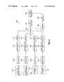
- FIGS. 7 and 8Parallel and serial versions of the receiver 700 for the CDM satellite transmission system 100 are shown in FIGS. 7 and 8 , respectively.
- the received signal(converted to a digital signal by an analog-to-digital converter) is applied to a bank of rake receivers 710 -n in the parallel implementation.
- the rake receivers 710 -neach provide a bank of fingers, with each finger having on-time, delayed and pilot processing.
- the rake receivers 710 -ninclude composite fingers that can track the on-time and delayed versions of the same primary channel.
- the rake receiver 710 - 6( 710 -d in the serial implementation) includes a composite finger that can track the tuning channel.
- the received signal corresponding to satellite two ( 120 )is received by rake receivers 710 - 3 (enhancement), 710 - 4 (enhancement) and 710 - 6 (core-tuning).
- the enhancement layeris then de-interleaved at stage 720 , using the same interleaver delay, D 1 , as the first interleaver 530 (four seconds).
- the de-interleaveris configured to unscramble signal bits or symbols that were scrambled over the first delay interval, to overcome signal losses due to fading over the transmission channel.
- the delay 740is utilized to synchronize the primary (enhancement) and tuning (core) channels, and is configured to introduce a time delay, T 5 .
- the delay, T 5introduced by the delay stage 740 is approximately 500 milliseconds.
- the core layer from satellite two ( 120 )is then de-interleaved at stage 730 , using an interleaver delay, D 2 , of 500 milliseconds.
- the output of the interleaver 730then bypasses a delay stage 750 having a delay, T 6 , set to zero seconds.
- the received signal corresponding to satellite one ( 110 )is received by rake receivers 710 - 1 (enhancement), 710 - 2 (enhancement) and 710 - 5 (core-tuning).
- the enhancement layeris then de-interleaved at stage 715 , using the same interleaver delay, D 1 , as the first interleaver 530 (four seconds).
- the delay 735is utilized to synchronize the enhancement and core channels of both satellites 110 , 120 , and is configured to introduce a time delay, T 3 .
- the delay, T 3introduced by the delay stage 735 is approximately 4.5 seconds.
- the core layer from satellite one ( 110 )is then de-interleaved at stage 725 , using an interleaver delay, D 1 , of four seconds.
- the output of the interleaver 725is then delayed at stage 745 having a delay, T 4 , set to 4.5 seconds.
- the de-interleaved signalsare all now properly aligned to account for the four second time shift between the on-time and delayed signals, as well as the delays introduced by the tuning channel.
- the outputs of the delay stages 735 , 740 , 745 and 750are combined at stage 760 (or 765 in an embodiment utilizing a second FEC coder 780 for the core layer).
- a decoder 770decodes the input signals according to the coding scheme used by the first FEC coder 520 of the transmitter section 500 .
- the FEC decoded signalis then applied to an audio/source decoder 790 .
- the audio/source decoder 790responds to the output of the primary channel only, or in combination with the output of the tuning channel. If the user selects a new channel, the audio/source decoder 790 is configured to respond only to the tuning channel.
- the programis then reproduced based only on information from the tuning channel, and the program reproduction delay is reduced to 500 milliseconds. In this manner, the user is able to obtain a reproduction of the program with minimal delay when tuning or switching among program channels.
- the audio/source decoder 790gradually resumes reproduction of the output of the enhancement layer, as the corresponding enhancement layer data becomes available.
- amplitude of the k- th sub-channel, A ikcan be specified on a per-sub-channel basis. In this manner, more power can be allocated for more important sub-channels. For example, within an audio program it may be desirable to emphasize the core layer for tuning purposes.
- ⁇ ilis the multipath delay for the l-th path from the i-th satellite
- g iis the path gain
- ⁇ im ⁇ ( n )1 T ⁇ ⁇ nT + ⁇ im nT + T + ⁇ im ⁇ r ⁇ ( t ) ⁇ c il * ⁇ ( t - ⁇ im ) ⁇ d t Eq . ( 3 ) where each path rake finger is tuned to a multipath.
- ⁇ im ⁇ ( n )1 ⁇ ⁇ ⁇ nT + ⁇ im - ( ⁇ - T ) / 2 nT + T + ⁇ im + ( ⁇ - T ) / 2 ⁇ r ⁇ ( t ) ⁇ c i0 * ⁇ ( t - ⁇ im ) ⁇ d t Eq . ( 4 ) where the rake is tuned to the pilot channel.
- the mobile receiver 150can employ dual receive antennas for the spatial filtering of the two satellite signals.
- This technologyis referred to as “beam forming,” and is described in R. T. Compton, Jr., Adaptive Antennas: Concepts and Performance (Prentice Hall, 1988). It is a well known result that two antenna elements can null one interfering source.
- the antenna patterncan be adaptively changed to pick up only one satellite signal and null out the other satellite signal.
- the powercan be adaptively allocated to those channels so that the capacity of the CDM system 100 can be maximized.
- the bit-rate of the sourceis low and the energy that is assigned to the talk channel can be lowered as well.
Landscapes
- Engineering & Computer Science (AREA)
- Signal Processing (AREA)
- Computer Networks & Wireless Communication (AREA)
- Physics & Mathematics (AREA)
- Astronomy & Astrophysics (AREA)
- General Physics & Mathematics (AREA)
- Aviation & Aerospace Engineering (AREA)
- Multimedia (AREA)
- Radio Relay Systems (AREA)
- Error Detection And Correction (AREA)
- Detection And Prevention Of Errors In Transmission (AREA)
Abstract
Description
where Aikis the amplitude of the k-thsub-channel, K is the number of audio channels, cikis the signature code sequence for the k-thchannel and the i-th satellite, and bikis the complex QPSK symbol for each sub-channel. Thus, in accordance with the present invention, amplitude of the k-thsub-channel, Aik, can be specified on a per-sub-channel basis. In this manner, more power can be allocated for more important sub-channels. For example, within an audio program it may be desirable to emphasize the core layer for tuning purposes.
where τilis the multipath delay for the l-th path from the i-th satellite, v(t) with E{v(t)v*(t+τ)}=N0δ(τ), is the additive white Gaussian noice (AWGN) introduced by the receiver and ψ represents carrier frequency offsets, giis the path gain, and hi(t) (=Σlhil(t−τil)) is the impulse response from satellite, Si, to the
where each path rake finger is tuned to a multipath. The corresponding pilot signal component for this rake branch is given by:
where the rake is tuned to the pilot channel.
where Micontains the indices corresponding to the Ml-largest values of |him(n)|2.
Claims (61)
Priority Applications (4)
| Application Number | Priority Date | Filing Date | Title |
|---|---|---|---|
| US09/250,743US6876623B1 (en) | 1998-12-02 | 1999-02-16 | Tuning scheme for code division multiplex broadcasting system |
| DE2000633209DE60033209T2 (en) | 1999-02-16 | 2000-02-09 | Voting system for code division multiplex broadcasting system |
| EP20000300992EP1030463B1 (en) | 1999-02-16 | 2000-02-09 | Tuning scheme for code division multiplex broadcasting system |
| JP2000037109AJP4323661B2 (en) | 1999-02-16 | 2000-02-15 | Satellite broadcasting signal broadcasting and receiving method and satellite broadcasting system |
Applications Claiming Priority (3)
| Application Number | Priority Date | Filing Date | Title |
|---|---|---|---|
| US09/203,663US6370666B1 (en) | 1998-12-02 | 1998-12-02 | Tuning scheme for error-corrected broadcast programs |
| US09/220,722US6728202B1 (en) | 1998-12-24 | 1998-12-24 | Code division multiplex satellite broadcasting system |
| US09/250,743US6876623B1 (en) | 1998-12-02 | 1999-02-16 | Tuning scheme for code division multiplex broadcasting system |
Related Parent Applications (1)
| Application Number | Title | Priority Date | Filing Date |
|---|---|---|---|
| US09/220,722Continuation-In-PartUS6728202B1 (en) | 1998-12-02 | 1998-12-24 | Code division multiplex satellite broadcasting system |
Publications (1)
| Publication Number | Publication Date |
|---|---|
| US6876623B1true US6876623B1 (en) | 2005-04-05 |
Family
ID=34380650
Family Applications (1)
| Application Number | Title | Priority Date | Filing Date |
|---|---|---|---|
| US09/250,743Expired - LifetimeUS6876623B1 (en) | 1998-12-02 | 1999-02-16 | Tuning scheme for code division multiplex broadcasting system |
Country Status (1)
| Country | Link |
|---|---|
| US (1) | US6876623B1 (en) |
Cited By (52)
| Publication number | Priority date | Publication date | Assignee | Title |
|---|---|---|---|---|
| US20030227885A1 (en)* | 2002-06-07 | 2003-12-11 | Sandbridge Technologies Inc. | Method of first interleavering of a two interleaver transmitter |
| US20040137929A1 (en)* | 2000-11-30 | 2004-07-15 | Jones Aled Wynne | Communication system |
| US20040239371A1 (en)* | 2003-05-28 | 2004-12-02 | Lee Jung Hwa | Temperature detecting circuit |
| US20050053122A1 (en)* | 1997-01-16 | 2005-03-10 | Scientific Generics Limited | Signalling system |
| US20050219068A1 (en)* | 2000-11-30 | 2005-10-06 | Jones Aled W | Acoustic communication system |
| US20060013335A1 (en)* | 2004-07-19 | 2006-01-19 | Michael Leabman | Multi-connection, non-simultaneous frequency diversity in radio communication systems |
| US20070204196A1 (en)* | 2006-02-13 | 2007-08-30 | Digital Fountain, Inc. | Streaming and buffering using variable fec overhead and protection periods |
| US20080034273A1 (en)* | 1998-09-23 | 2008-02-07 | Digital Fountain, Inc. | Information additive code generator and decoder for communication systems |
| US20080056388A1 (en)* | 2000-09-26 | 2008-03-06 | Choi In H | Digital television system |
| WO2008034737A1 (en)* | 2006-09-22 | 2008-03-27 | Alcatel Lucent | Multi-input terrestrial repeater for a contents broadcasting system |
| US20080115007A1 (en)* | 2006-11-14 | 2008-05-15 | Qualcomm Incorporated | Efficient layered coding technique to mitigate shadowing in satellite propagation channel |
| WO2008131023A1 (en) | 2007-04-16 | 2008-10-30 | Digital Fountain, Inc. | Dynamic stream interleaving and sub-stream based delivery |
| US7460839B2 (en) | 2004-07-19 | 2008-12-02 | Purewave Networks, Inc. | Non-simultaneous frequency diversity in radio communication systems |
| US7505823B1 (en)* | 1999-07-30 | 2009-03-17 | Intrasonics Limited | Acoustic communication system |
| US20090158114A1 (en)* | 2003-10-06 | 2009-06-18 | Digital Fountain, Inc. | Error-correcting multi-stage code generator and decoder for communication systems having single transmitters or multiple transmitters |
| US20090307565A1 (en)* | 2004-08-11 | 2009-12-10 | Digital Fountain, Inc. | Method and apparatus for fast encoding of data symbols according to half-weight codes |
| US20090316835A1 (en)* | 2005-03-31 | 2009-12-24 | Qualcomm Incorporated | Power savings in hierarchically coded modulation |
| US20100007785A1 (en)* | 2000-10-02 | 2010-01-14 | In Hwan Choi | Vsb transmission system |
| US20100037106A1 (en)* | 2000-12-28 | 2010-02-11 | Lg Electronics Inc. | Vsb transmission system for processing supplemental transmission data |
| US20100073576A1 (en)* | 2001-01-19 | 2010-03-25 | Lg Electronics Inc. | Vsb reception system with enhanced signal detection for processing supplemental data |
| US20100122126A1 (en)* | 2001-04-18 | 2010-05-13 | Lg Electronics Inc. | Vsb communication system |
| US20110019769A1 (en)* | 2001-12-21 | 2011-01-27 | Qualcomm Incorporated | Multi stage code generator and decoder for communication systems |
| US20110096828A1 (en)* | 2009-09-22 | 2011-04-28 | Qualcomm Incorporated | Enhanced block-request streaming using scalable encoding |
| US20110231519A1 (en)* | 2006-06-09 | 2011-09-22 | Qualcomm Incorporated | Enhanced block-request streaming using url templates and construction rules |
| US20110238789A1 (en)* | 2006-06-09 | 2011-09-29 | Qualcomm Incorporated | Enhanced block-request streaming system using signaling or block creation |
| US8248528B2 (en) | 2001-12-24 | 2012-08-21 | Intrasonics S.A.R.L. | Captioning system |
| US8560913B2 (en) | 2008-05-29 | 2013-10-15 | Intrasonics S.A.R.L. | Data embedding system |
| WO2014098787A1 (en)* | 2012-12-17 | 2014-06-26 | Thomson Licensing | Robust digital channels |
| WO2014098789A1 (en)* | 2012-12-17 | 2014-06-26 | Thomson Licensing | Robust digital channels |
| US8806050B2 (en) | 2010-08-10 | 2014-08-12 | Qualcomm Incorporated | Manifest file updates for network streaming of coded multimedia data |
| US8890744B1 (en) | 1999-04-07 | 2014-11-18 | James L. Geer | Method and apparatus for the detection of objects using electromagnetic wave attenuation patterns |
| US8918533B2 (en) | 2010-07-13 | 2014-12-23 | Qualcomm Incorporated | Video switching for streaming video data |
| US8958375B2 (en) | 2011-02-11 | 2015-02-17 | Qualcomm Incorporated | Framing for an improved radio link protocol including FEC |
| US9136878B2 (en) | 2004-05-07 | 2015-09-15 | Digital Fountain, Inc. | File download and streaming system |
| US9185439B2 (en) | 2010-07-15 | 2015-11-10 | Qualcomm Incorporated | Signaling data for multiplexing video components |
| US9191151B2 (en) | 2006-06-09 | 2015-11-17 | Qualcomm Incorporated | Enhanced block-request streaming using cooperative parallel HTTP and forward error correction |
| US9237101B2 (en) | 2007-09-12 | 2016-01-12 | Digital Fountain, Inc. | Generating and communicating source identification information to enable reliable communications |
| US9236885B2 (en) | 2002-10-05 | 2016-01-12 | Digital Fountain, Inc. | Systematic encoding and decoding of chain reaction codes |
| US9240810B2 (en) | 2002-06-11 | 2016-01-19 | Digital Fountain, Inc. | Systems and processes for decoding chain reaction codes through inactivation |
| US9253233B2 (en) | 2011-08-31 | 2016-02-02 | Qualcomm Incorporated | Switch signaling methods providing improved switching between representations for adaptive HTTP streaming |
| US9264069B2 (en) | 2006-05-10 | 2016-02-16 | Digital Fountain, Inc. | Code generator and decoder for communications systems operating using hybrid codes to allow for multiple efficient uses of the communications systems |
| US9270299B2 (en) | 2011-02-11 | 2016-02-23 | Qualcomm Incorporated | Encoding and decoding using elastic codes with flexible source block mapping |
| US9270414B2 (en) | 2006-02-21 | 2016-02-23 | Digital Fountain, Inc. | Multiple-field based code generator and decoder for communications systems |
| US9281847B2 (en) | 2009-02-27 | 2016-03-08 | Qualcomm Incorporated | Mobile reception of digital video broadcasting—terrestrial services |
| US9288010B2 (en) | 2009-08-19 | 2016-03-15 | Qualcomm Incorporated | Universal file delivery methods for providing unequal error protection and bundled file delivery services |
| US9294226B2 (en) | 2012-03-26 | 2016-03-22 | Qualcomm Incorporated | Universal object delivery and template-based file delivery |
| US9380096B2 (en) | 2006-06-09 | 2016-06-28 | Qualcomm Incorporated | Enhanced block-request streaming system for handling low-latency streaming |
| US9419749B2 (en) | 2009-08-19 | 2016-08-16 | Qualcomm Incorporated | Methods and apparatus employing FEC codes with permanent inactivation of symbols for encoding and decoding processes |
| US9485546B2 (en) | 2010-06-29 | 2016-11-01 | Qualcomm Incorporated | Signaling video samples for trick mode video representations |
| US9596447B2 (en) | 2010-07-21 | 2017-03-14 | Qualcomm Incorporated | Providing frame packing type information for video coding |
| US9843844B2 (en) | 2011-10-05 | 2017-12-12 | Qualcomm Incorporated | Network streaming of media data |
| US9917874B2 (en) | 2009-09-22 | 2018-03-13 | Qualcomm Incorporated | Enhanced block-request streaming using block partitioning or request controls for improved client-side handling |
Citations (20)
| Publication number | Priority date | Publication date | Assignee | Title |
|---|---|---|---|---|
| US5029185A (en)* | 1989-07-28 | 1991-07-02 | At&T Bell Laboratories | Coded modulation for mobile radio |
| US5278863A (en) | 1992-04-10 | 1994-01-11 | Cd Radio Incorporated | Radio frequency broadcasting systems and methods using two low-cost geosynchronous satellites |
| US5485485A (en) | 1992-04-10 | 1996-01-16 | Cd Radio Inc. | Radio frequency broadcasting systems and methods using two low-cost geosynchronous satellites and hemispherical coverage antennas |
| US5572332A (en)* | 1991-11-26 | 1996-11-05 | Goldstar Co., Ltd. | Video cassette recorder for simultaneously recording broadcasting signals of two channels and selectively playing back the recorded two channel broadcasting signals |
| US5592471A (en) | 1995-04-21 | 1997-01-07 | Cd Radio Inc. | Mobile radio receivers using time diversity to avoid service outages in multichannel broadcast transmission systems |
| WO1997049207A1 (en) | 1996-06-19 | 1997-12-24 | Kumar Derek D | In-band on-channel digital broadcasting method and system |
| US5794138A (en) | 1997-02-26 | 1998-08-11 | Cd Radio Inc. | Satellite broadcast system receiver |
| US5838669A (en)* | 1996-08-28 | 1998-11-17 | At&T Corp. | Method of synchronizing satellite switched CDMA communication system |
| US5926510A (en)* | 1996-01-29 | 1999-07-20 | Sony Corporation | Transmitter apparatus, receiver apparatus, transmitting method and receiving method for interleaving and varying an antenna directional pattern |
| US5930706A (en)* | 1995-11-29 | 1999-07-27 | Ericsson Inc. | Detecting messages transmitted over a communications channel such as a paging channel |
| US6035433A (en)* | 1995-05-18 | 2000-03-07 | Sony Corporation | Data recording/reproducing apparatus corresponding to a plurality of error correcting system and a data recording medium |
| US6044166A (en)* | 1995-01-17 | 2000-03-28 | Sarnoff Corporation | Parallel-pipelined image processing system |
| US6064441A (en)* | 1997-05-13 | 2000-05-16 | Sony Corporation | Receiving method and apparatus in which received broadcasting data read out of a memory contains marks representing a partition of the data |
| EP1014608A2 (en) | 1998-12-24 | 2000-06-28 | Lucent Technologies Inc. | Satellite broadcasting system using code division multiplex transmission |
| US6128330A (en)* | 1998-11-24 | 2000-10-03 | Linex Technology, Inc. | Efficient shadow reduction antenna system for spread spectrum |
| US6144707A (en)* | 1997-04-23 | 2000-11-07 | Sony Corporation | Apparatus for receiving broadcasting signals |
| US6198748B1 (en)* | 1997-09-02 | 2001-03-06 | Motorola, Inc. | Data transmission system and method |
| US6282412B1 (en)* | 1998-07-22 | 2001-08-28 | Lucent Technologies Inc. | Geographically adaptive portable broadcast receiver |
| US6333926B1 (en)* | 1998-08-11 | 2001-12-25 | Nortel Networks Limited | Multiple user CDMA basestation modem |
| US6549241B2 (en)* | 1998-12-11 | 2003-04-15 | Hitachi America, Ltd. | Methods and apparatus for processing multimedia broadcasts |
- 1999
- 1999-02-16USUS09/250,743patent/US6876623B1/ennot_activeExpired - Lifetime
Patent Citations (21)
| Publication number | Priority date | Publication date | Assignee | Title |
|---|---|---|---|---|
| US5029185A (en)* | 1989-07-28 | 1991-07-02 | At&T Bell Laboratories | Coded modulation for mobile radio |
| US5572332A (en)* | 1991-11-26 | 1996-11-05 | Goldstar Co., Ltd. | Video cassette recorder for simultaneously recording broadcasting signals of two channels and selectively playing back the recorded two channel broadcasting signals |
| US5278863A (en) | 1992-04-10 | 1994-01-11 | Cd Radio Incorporated | Radio frequency broadcasting systems and methods using two low-cost geosynchronous satellites |
| US5319673A (en) | 1992-04-10 | 1994-06-07 | Cd Radio Inc. | Radio frequency broadcasting systems and methods using two low-cost geosynchronous satellites |
| US5485485A (en) | 1992-04-10 | 1996-01-16 | Cd Radio Inc. | Radio frequency broadcasting systems and methods using two low-cost geosynchronous satellites and hemispherical coverage antennas |
| US6044166A (en)* | 1995-01-17 | 2000-03-28 | Sarnoff Corporation | Parallel-pipelined image processing system |
| US5592471A (en) | 1995-04-21 | 1997-01-07 | Cd Radio Inc. | Mobile radio receivers using time diversity to avoid service outages in multichannel broadcast transmission systems |
| US6035433A (en)* | 1995-05-18 | 2000-03-07 | Sony Corporation | Data recording/reproducing apparatus corresponding to a plurality of error correcting system and a data recording medium |
| US5930706A (en)* | 1995-11-29 | 1999-07-27 | Ericsson Inc. | Detecting messages transmitted over a communications channel such as a paging channel |
| US5926510A (en)* | 1996-01-29 | 1999-07-20 | Sony Corporation | Transmitter apparatus, receiver apparatus, transmitting method and receiving method for interleaving and varying an antenna directional pattern |
| WO1997049207A1 (en) | 1996-06-19 | 1997-12-24 | Kumar Derek D | In-band on-channel digital broadcasting method and system |
| US5838669A (en)* | 1996-08-28 | 1998-11-17 | At&T Corp. | Method of synchronizing satellite switched CDMA communication system |
| US5794138A (en) | 1997-02-26 | 1998-08-11 | Cd Radio Inc. | Satellite broadcast system receiver |
| US6144707A (en)* | 1997-04-23 | 2000-11-07 | Sony Corporation | Apparatus for receiving broadcasting signals |
| US6064441A (en)* | 1997-05-13 | 2000-05-16 | Sony Corporation | Receiving method and apparatus in which received broadcasting data read out of a memory contains marks representing a partition of the data |
| US6198748B1 (en)* | 1997-09-02 | 2001-03-06 | Motorola, Inc. | Data transmission system and method |
| US6282412B1 (en)* | 1998-07-22 | 2001-08-28 | Lucent Technologies Inc. | Geographically adaptive portable broadcast receiver |
| US6333926B1 (en)* | 1998-08-11 | 2001-12-25 | Nortel Networks Limited | Multiple user CDMA basestation modem |
| US6128330A (en)* | 1998-11-24 | 2000-10-03 | Linex Technology, Inc. | Efficient shadow reduction antenna system for spread spectrum |
| US6549241B2 (en)* | 1998-12-11 | 2003-04-15 | Hitachi America, Ltd. | Methods and apparatus for processing multimedia broadcasts |
| EP1014608A2 (en) | 1998-12-24 | 2000-06-28 | Lucent Technologies Inc. | Satellite broadcasting system using code division multiplex transmission |
Non-Patent Citations (14)
| Title |
|---|
| "Digital Broadcasting Systems for Television, Sound and Data Services; Framing Structure, Channel Coding and Modulation for 11/12 GHz Satellite Services," European Telecommunications Standards Institute, XP-002220362, pp. 1-23 (Dec. 1994). |
| Chin-Lin I. and R. D. Gitlin, "Multi-Code CDMA Wireless Personal Communications Networks," Proc. of ICC '95, Seattle, Washington, pp. 1060-1064, Jun. 1995. |
| Cupo et al., "An OFDM All Digital In-Band-On-Channel (IBOC) AM and FM Radio Solution Using the PAC Encoder," IEEE Transaction on Broadcasting, IEEE Inc. New York, vol. 44, No. 1, XP-000834308, pp. 22-27 (Mar. 1998). |
| D.K. Sachdev, "The Worldspace System: Architecture, Plans and Technologies," Conf. Proc. Broadcast Asia 98, (Singapore), 219-228 (Jun. 1998). |
| E. Dahlman et al., , "UMTS/IMT-2000: Based on Wideband CDMA," IEEE Communications Magazine, vol. 36, pp. 70-81, Sep. 1998. |
| E. Lutz et al., "The Land Mobile Satellite Communication Channel-Recording, Statistics, and Channel Model," IEEE Trans. on Vehicular Technology, vol. 40, 375-386, (May 1991). |
| J. Herre et al., "The Integrated Filterbank Based Scalable MPEG-4 Audio Coder," 105<th >AES Convention, San Francisco, CA, Sep. 1998. |
| J. S. Lehnert and M.B. Pursley, Multipath Diversity Reception of Spread-Spectrum Multiple-Access Communications, IEEE Trans. On Communications, vol. 35, 1189-1198 (Nov. 1987). |
| L. Thibault et al., "EIA/NRSC DAR Systems Subjective Tests, Part II: Transmission Impairments," IEEE Trans. on Broadcasting, vol. 43, 353-364 (Dec. 1997). |
| M. Kavehrad and B. Ramamurthi, "Direct-Sequence Spread Spectrum with DPSK Modulation and Diversity for Indoor Wireless Communications," IEEE Trans. On Communications, vol. 35, 224-236 (Feb. 1987). |
| R. D. Briskman, "Satellite DAB," International Journal of Satellite Communications, vol. 13, pp. 259-266, 1995. |
| S. G. Wilson, Digital Modulation and Coding, 463-65, New Jersey: Prentice Hall, 1996. |
| V. Weerackody, "Effect of Time Diversity on the Forward Link of the DS-CDMA Cellular System," Wireless Personal Communications, vol. 7, 89-109 (Aug. 1998). |
| W.C. Jakes, Microwave Mobile Communications, 13-16, (John Wiley & Sons, 1974). |
Cited By (115)
| Publication number | Priority date | Publication date | Assignee | Title |
|---|---|---|---|---|
| US20050053122A1 (en)* | 1997-01-16 | 2005-03-10 | Scientific Generics Limited | Signalling system |
| US7796676B2 (en) | 1997-01-16 | 2010-09-14 | Intrasonics Limited | Signalling system |
| US20080034273A1 (en)* | 1998-09-23 | 2008-02-07 | Digital Fountain, Inc. | Information additive code generator and decoder for communication systems |
| US9246633B2 (en) | 1998-09-23 | 2016-01-26 | Digital Fountain, Inc. | Information additive code generator and decoder for communication systems |
| US8890744B1 (en) | 1999-04-07 | 2014-11-18 | James L. Geer | Method and apparatus for the detection of objects using electromagnetic wave attenuation patterns |
| US7505823B1 (en)* | 1999-07-30 | 2009-03-17 | Intrasonics Limited | Acoustic communication system |
| US20100275095A1 (en)* | 2000-09-26 | 2010-10-28 | In Hwan Choi | Digital television system |
| US9756334B2 (en) | 2000-09-26 | 2017-09-05 | Lg Electronics Inc. | Digital television system |
| US20080056388A1 (en)* | 2000-09-26 | 2008-03-06 | Choi In H | Digital television system |
| US8743971B2 (en) | 2000-09-26 | 2014-06-03 | Lg Electronics Inc. | Digital television system |
| US8428150B2 (en) | 2000-09-26 | 2013-04-23 | Lg Electronics Inc. | Digital television system |
| US20100017689A1 (en)* | 2000-10-02 | 2010-01-21 | In Hwan Choi | Vsb transmission system |
| US7894549B2 (en)* | 2000-10-02 | 2011-02-22 | Lg Electronics Inc. | VSB transmission system |
| US20100007785A1 (en)* | 2000-10-02 | 2010-01-14 | In Hwan Choi | Vsb transmission system |
| US8320485B2 (en) | 2000-10-02 | 2012-11-27 | Lg Electronics Inc. | VSB transmission system |
| US20100240297A1 (en)* | 2000-11-30 | 2010-09-23 | Intrasonics Limited | Communication system |
| US7460991B2 (en) | 2000-11-30 | 2008-12-02 | Intrasonics Limited | System and method for shaping a data signal for embedding within an audio signal |
| US8185100B2 (en) | 2000-11-30 | 2012-05-22 | Intrasonics S.A.R.L. | Communication system |
| US7796978B2 (en) | 2000-11-30 | 2010-09-14 | Intrasonics S.A.R.L. | Communication system for receiving and transmitting data using an acoustic data channel |
| US20040137929A1 (en)* | 2000-11-30 | 2004-07-15 | Jones Aled Wynne | Communication system |
| US20050219068A1 (en)* | 2000-11-30 | 2005-10-06 | Jones Aled W | Acoustic communication system |
| US8130833B2 (en) | 2000-12-28 | 2012-03-06 | Lg Electronics Inc. | VSB transmission system for processing supplemental transmission data |
| US20100037106A1 (en)* | 2000-12-28 | 2010-02-11 | Lg Electronics Inc. | Vsb transmission system for processing supplemental transmission data |
| US8059718B2 (en) | 2000-12-28 | 2011-11-15 | Lg Electronics Inc. | VSB transmission system for processing supplemental transmission data |
| US20100033636A1 (en)* | 2000-12-28 | 2010-02-11 | In Hwan Choi | Vsb transmission system for processing supplemental transmission data |
| US7782404B2 (en) | 2001-01-19 | 2010-08-24 | Lg Electronics Inc. | VSB reception system with enhanced signal detection for processing supplemental data |
| US7787054B2 (en) | 2001-01-19 | 2010-08-31 | Lg Electronics Inc. | VSB reception system with enhanced signal detection for processing supplemental data |
| US7911539B2 (en) | 2001-01-19 | 2011-03-22 | Lg Electronics Inc. | VSB reception system with enhanced signal detection for processing supplemental data |
| US20100073576A1 (en)* | 2001-01-19 | 2010-03-25 | Lg Electronics Inc. | Vsb reception system with enhanced signal detection for processing supplemental data |
| US20100073570A1 (en)* | 2001-01-19 | 2010-03-25 | Lg Electronics Inc. | Vsb reception system with enhanced signal detection for processing supplemental data |
| US20100073575A1 (en)* | 2001-01-19 | 2010-03-25 | Lg Electronics Inc. | Vsb reception system with enhanced signal detection for processing supplemental data |
| US20100278274A1 (en)* | 2001-01-19 | 2010-11-04 | Lg Electronics Inc. | Vsb reception system with enhanced signal detection for processing supplemental data |
| US20110129019A1 (en)* | 2001-01-19 | 2011-06-02 | In Hwan Choi | Vsb reception system with enhanced signal detection for processing supplemental data |
| US7787053B2 (en) | 2001-01-19 | 2010-08-31 | Lg Electronics Inc. | VSB reception system with enhanced signal detection for processing supplemental data |
| US8164691B2 (en) | 2001-01-19 | 2012-04-24 | Lg Electronics Inc. | VSB reception system with enhanced signal detection for processing supplemental data |
| US20100122126A1 (en)* | 2001-04-18 | 2010-05-13 | Lg Electronics Inc. | Vsb communication system |
| US7856651B2 (en) | 2001-04-18 | 2010-12-21 | Lg Electronics Inc. | VSB communication system |
| US20110007822A1 (en)* | 2001-04-18 | 2011-01-13 | Lg Electronics Inc. | Vsb communication system |
| US20110019769A1 (en)* | 2001-12-21 | 2011-01-27 | Qualcomm Incorporated | Multi stage code generator and decoder for communication systems |
| US9236976B2 (en) | 2001-12-21 | 2016-01-12 | Digital Fountain, Inc. | Multi stage code generator and decoder for communication systems |
| US8248528B2 (en) | 2001-12-24 | 2012-08-21 | Intrasonics S.A.R.L. | Captioning system |
| US7236480B2 (en)* | 2002-06-07 | 2007-06-26 | Sandbridge Technologies, Inc. | Method of first interleaving of a two interleaver transmitter |
| US20030227885A1 (en)* | 2002-06-07 | 2003-12-11 | Sandbridge Technologies Inc. | Method of first interleavering of a two interleaver transmitter |
| US9240810B2 (en) | 2002-06-11 | 2016-01-19 | Digital Fountain, Inc. | Systems and processes for decoding chain reaction codes through inactivation |
| US9236885B2 (en) | 2002-10-05 | 2016-01-12 | Digital Fountain, Inc. | Systematic encoding and decoding of chain reaction codes |
| US20040239371A1 (en)* | 2003-05-28 | 2004-12-02 | Lee Jung Hwa | Temperature detecting circuit |
| US6967521B2 (en)* | 2003-05-28 | 2005-11-22 | Hynix Semiconductor Inc. | Temperature detecting circuit |
| US20090158114A1 (en)* | 2003-10-06 | 2009-06-18 | Digital Fountain, Inc. | Error-correcting multi-stage code generator and decoder for communication systems having single transmitters or multiple transmitters |
| US8887020B2 (en) | 2003-10-06 | 2014-11-11 | Digital Fountain, Inc. | Error-correcting multi-stage code generator and decoder for communication systems having single transmitters or multiple transmitters |
| US9136878B2 (en) | 2004-05-07 | 2015-09-15 | Digital Fountain, Inc. | File download and streaming system |
| US9236887B2 (en) | 2004-05-07 | 2016-01-12 | Digital Fountain, Inc. | File download and streaming system |
| US20060013335A1 (en)* | 2004-07-19 | 2006-01-19 | Michael Leabman | Multi-connection, non-simultaneous frequency diversity in radio communication systems |
| US7586862B2 (en) | 2004-07-19 | 2009-09-08 | Pure Wave Networks, Inc. | Multi-connection, non-simultaneous frequency diversity in radio communication systems |
| US7460839B2 (en) | 2004-07-19 | 2008-12-02 | Purewave Networks, Inc. | Non-simultaneous frequency diversity in radio communication systems |
| US7263335B2 (en) | 2004-07-19 | 2007-08-28 | Purewave Networks, Inc. | Multi-connection, non-simultaneous frequency diversity in radio communication systems |
| US7680470B2 (en) | 2004-07-19 | 2010-03-16 | Purewave Networks, Inc. | Multi-connection, non-simultaneous frequency diversity in radio communication systems |
| US20090307565A1 (en)* | 2004-08-11 | 2009-12-10 | Digital Fountain, Inc. | Method and apparatus for fast encoding of data symbols according to half-weight codes |
| US8874998B2 (en)* | 2005-03-31 | 2014-10-28 | Qualcomm Incorporated | Power savings in hierarchically coded modulation |
| US20100220816A1 (en)* | 2005-03-31 | 2010-09-02 | Qualcomm Incorporated | Power savings in hierarchically coded modulation |
| US20090316835A1 (en)* | 2005-03-31 | 2009-12-24 | Qualcomm Incorporated | Power savings in hierarchically coded modulation |
| US8737470B2 (en)* | 2005-03-31 | 2014-05-27 | Qualcomm Incorporated | Power savings in hierarchically coded modulation |
| US20070204196A1 (en)* | 2006-02-13 | 2007-08-30 | Digital Fountain, Inc. | Streaming and buffering using variable fec overhead and protection periods |
| US9136983B2 (en) | 2006-02-13 | 2015-09-15 | Digital Fountain, Inc. | Streaming and buffering using variable FEC overhead and protection periods |
| US9270414B2 (en) | 2006-02-21 | 2016-02-23 | Digital Fountain, Inc. | Multiple-field based code generator and decoder for communications systems |
| US9264069B2 (en) | 2006-05-10 | 2016-02-16 | Digital Fountain, Inc. | Code generator and decoder for communications systems operating using hybrid codes to allow for multiple efficient uses of the communications systems |
| US9432433B2 (en) | 2006-06-09 | 2016-08-30 | Qualcomm Incorporated | Enhanced block-request streaming system using signaling or block creation |
| US9380096B2 (en) | 2006-06-09 | 2016-06-28 | Qualcomm Incorporated | Enhanced block-request streaming system for handling low-latency streaming |
| US11477253B2 (en) | 2006-06-09 | 2022-10-18 | Qualcomm Incorporated | Enhanced block-request streaming system using signaling or block creation |
| US9628536B2 (en) | 2006-06-09 | 2017-04-18 | Qualcomm Incorporated | Enhanced block-request streaming using cooperative parallel HTTP and forward error correction |
| US9209934B2 (en) | 2006-06-09 | 2015-12-08 | Qualcomm Incorporated | Enhanced block-request streaming using cooperative parallel HTTP and forward error correction |
| US9191151B2 (en) | 2006-06-09 | 2015-11-17 | Qualcomm Incorporated | Enhanced block-request streaming using cooperative parallel HTTP and forward error correction |
| US20110231519A1 (en)* | 2006-06-09 | 2011-09-22 | Qualcomm Incorporated | Enhanced block-request streaming using url templates and construction rules |
| US9386064B2 (en) | 2006-06-09 | 2016-07-05 | Qualcomm Incorporated | Enhanced block-request streaming using URL templates and construction rules |
| US20110238789A1 (en)* | 2006-06-09 | 2011-09-29 | Qualcomm Incorporated | Enhanced block-request streaming system using signaling or block creation |
| US9178535B2 (en) | 2006-06-09 | 2015-11-03 | Digital Fountain, Inc. | Dynamic stream interleaving and sub-stream based delivery |
| KR101317093B1 (en) | 2006-09-22 | 2013-10-11 | 알까뗄 루슨트 | Multi-input terrestrial repeater for a contents broadcasting system |
| WO2008034737A1 (en)* | 2006-09-22 | 2008-03-27 | Alcatel Lucent | Multi-input terrestrial repeater for a contents broadcasting system |
| FR2906422A1 (en)* | 2006-09-22 | 2008-03-28 | Alcatel Sa | MULTI-INPUT TERRESTRIAL REPEATER FOR A CONTENT BROADCASTING SYSTEM |
| US8358607B2 (en) | 2006-09-22 | 2013-01-22 | Alcatel Lucent | Multiple entry terrestrial repeater for a content broadcasting system |
| CN101517925B (en)* | 2006-09-22 | 2012-11-28 | 阿尔卡特朗讯公司 | Multi-Input Terrestrial Repeater for Content Broadcasting Systems |
| US8750088B2 (en)* | 2006-11-14 | 2014-06-10 | Qualcomm Incorporated | Efficient layered coding technique to mitigate shadowing in satellite propagation channel |
| US20080115007A1 (en)* | 2006-11-14 | 2008-05-15 | Qualcomm Incorporated | Efficient layered coding technique to mitigate shadowing in satellite propagation channel |
| EP2145390A4 (en)* | 2007-04-16 | 2012-11-07 | Digital Fountain Inc | Dynamic stream interleaving and sub-stream based delivery |
| WO2008131023A1 (en) | 2007-04-16 | 2008-10-30 | Digital Fountain, Inc. | Dynamic stream interleaving and sub-stream based delivery |
| US9237101B2 (en) | 2007-09-12 | 2016-01-12 | Digital Fountain, Inc. | Generating and communicating source identification information to enable reliable communications |
| US8560913B2 (en) | 2008-05-29 | 2013-10-15 | Intrasonics S.A.R.L. | Data embedding system |
| US9281847B2 (en) | 2009-02-27 | 2016-03-08 | Qualcomm Incorporated | Mobile reception of digital video broadcasting—terrestrial services |
| US9288010B2 (en) | 2009-08-19 | 2016-03-15 | Qualcomm Incorporated | Universal file delivery methods for providing unequal error protection and bundled file delivery services |
| US9419749B2 (en) | 2009-08-19 | 2016-08-16 | Qualcomm Incorporated | Methods and apparatus employing FEC codes with permanent inactivation of symbols for encoding and decoding processes |
| US9876607B2 (en) | 2009-08-19 | 2018-01-23 | Qualcomm Incorporated | Methods and apparatus employing FEC codes with permanent inactivation of symbols for encoding and decoding processes |
| US9660763B2 (en) | 2009-08-19 | 2017-05-23 | Qualcomm Incorporated | Methods and apparatus employing FEC codes with permanent inactivation of symbols for encoding and decoding processes |
| US9917874B2 (en) | 2009-09-22 | 2018-03-13 | Qualcomm Incorporated | Enhanced block-request streaming using block partitioning or request controls for improved client-side handling |
| US10855736B2 (en) | 2009-09-22 | 2020-12-01 | Qualcomm Incorporated | Enhanced block-request streaming using block partitioning or request controls for improved client-side handling |
| US11743317B2 (en) | 2009-09-22 | 2023-08-29 | Qualcomm Incorporated | Enhanced block-request streaming using block partitioning or request controls for improved client-side handling |
| US11770432B2 (en) | 2009-09-22 | 2023-09-26 | Qualcomm Incorporated | Enhanced block-request streaming system for handling low-latency streaming |
| US12155715B2 (en) | 2009-09-22 | 2024-11-26 | Qualcomm Incorporated | Enhanced block-request streaming using block partitioning or request controls for improved client-side handling |
| US20110096828A1 (en)* | 2009-09-22 | 2011-04-28 | Qualcomm Incorporated | Enhanced block-request streaming using scalable encoding |
| US9992555B2 (en) | 2010-06-29 | 2018-06-05 | Qualcomm Incorporated | Signaling random access points for streaming video data |
| US9485546B2 (en) | 2010-06-29 | 2016-11-01 | Qualcomm Incorporated | Signaling video samples for trick mode video representations |
| US8918533B2 (en) | 2010-07-13 | 2014-12-23 | Qualcomm Incorporated | Video switching for streaming video data |
| US9185439B2 (en) | 2010-07-15 | 2015-11-10 | Qualcomm Incorporated | Signaling data for multiplexing video components |
| US9602802B2 (en) | 2010-07-21 | 2017-03-21 | Qualcomm Incorporated | Providing frame packing type information for video coding |
| US9596447B2 (en) | 2010-07-21 | 2017-03-14 | Qualcomm Incorporated | Providing frame packing type information for video coding |
| US8806050B2 (en) | 2010-08-10 | 2014-08-12 | Qualcomm Incorporated | Manifest file updates for network streaming of coded multimedia data |
| US9456015B2 (en) | 2010-08-10 | 2016-09-27 | Qualcomm Incorporated | Representation groups for network streaming of coded multimedia data |
| US9319448B2 (en) | 2010-08-10 | 2016-04-19 | Qualcomm Incorporated | Trick modes for network streaming of coded multimedia data |
| US9270299B2 (en) | 2011-02-11 | 2016-02-23 | Qualcomm Incorporated | Encoding and decoding using elastic codes with flexible source block mapping |
| US8958375B2 (en) | 2011-02-11 | 2015-02-17 | Qualcomm Incorporated | Framing for an improved radio link protocol including FEC |
| US9253233B2 (en) | 2011-08-31 | 2016-02-02 | Qualcomm Incorporated | Switch signaling methods providing improved switching between representations for adaptive HTTP streaming |
| US9843844B2 (en) | 2011-10-05 | 2017-12-12 | Qualcomm Incorporated | Network streaming of media data |
| US9294226B2 (en) | 2012-03-26 | 2016-03-22 | Qualcomm Incorporated | Universal object delivery and template-based file delivery |
| US9936226B2 (en) | 2012-12-17 | 2018-04-03 | Thomson Licensing | Robust digital channels |
| US10499112B2 (en) | 2012-12-17 | 2019-12-03 | Interdigital Ce Patent Holdings | Robust digital channels |
| WO2014098787A1 (en)* | 2012-12-17 | 2014-06-26 | Thomson Licensing | Robust digital channels |
| WO2014098789A1 (en)* | 2012-12-17 | 2014-06-26 | Thomson Licensing | Robust digital channels |
Similar Documents
| Publication | Publication Date | Title |
|---|---|---|
| US6876623B1 (en) | Tuning scheme for code division multiplex broadcasting system | |
| JP4017987B2 (en) | Method and apparatus for concatenated convolutional encoding and interleaving | |
| US5907582A (en) | System for turbo-coded satellite digital audio broadcasting | |
| US6370666B1 (en) | Tuning scheme for error-corrected broadcast programs | |
| CA2758312C (en) | Method and apparatus for continuous cross-channel interleaving | |
| US8750088B2 (en) | Efficient layered coding technique to mitigate shadowing in satellite propagation channel | |
| US6055277A (en) | Communication system for broadcasting to mobile users | |
| US5912917A (en) | Digital broadcast system | |
| EP1030463B1 (en) | Tuning scheme for code division multiplex broadcasting system | |
| US20040092228A1 (en) | Apparatus and method for enabling use of low power satellites, such as C-band, to broadcast to mobile and non-directional receivers, and signal design therefor | |
| JP2002533014A (en) | Information transmitting apparatus and method, and information receiving apparatus and method | |
| US6728202B1 (en) | Code division multiplex satellite broadcasting system | |
| JP2002508623A (en) | Digital broadcasting system using satellite direct broadcasting and terrestrial repeater | |
| Lou et al. | FEC scheme for a TDM-OFDM based satellite radio broadcasting system | |
| Weerackody et al. | A code division multiplexing scheme for satellite digital audio broadcasting | |
| HK1036170A (en) | Digital broadcast system using satellite direct broadcast and terrestrial repeater |
Legal Events
| Date | Code | Title | Description |
|---|---|---|---|
| AS | Assignment | Owner name:LUCENT TECHNOLOGIES INC., NEW JERSEY Free format text:ASSIGNMENT OF ASSIGNORS INTEREST;ASSIGNORS:LOU, HUI-LING;SAYEED, ZULFIQUAR;WEERACKODY, VIJITHA;REEL/FRAME:009867/0105;SIGNING DATES FROM 19990312 TO 19990315 | |
| STCF | Information on status: patent grant | Free format text:PATENTED CASE | |
| CC | Certificate of correction | ||
| AS | Assignment | Owner name:AGERE SYSTEMS INC., PENNSYLVANIA Free format text:ASSIGNMENT OF ASSIGNORS INTEREST;ASSIGNOR:LUCENT TECHNOLOGIES INC.;REEL/FRAME:020733/0299 Effective date:20010130 | |
| FPAY | Fee payment | Year of fee payment:4 | |
| FPAY | Fee payment | Year of fee payment:8 | |
| AS | Assignment | Owner name:DEUTSCHE BANK AG NEW YORK BRANCH, AS COLLATERAL AG Free format text:PATENT SECURITY AGREEMENT;ASSIGNORS:LSI CORPORATION;AGERE SYSTEMS LLC;REEL/FRAME:032856/0031 Effective date:20140506 | |
| AS | Assignment | Owner name:AVAGO TECHNOLOGIES GENERAL IP (SINGAPORE) PTE. LTD Free format text:ASSIGNMENT OF ASSIGNORS INTEREST;ASSIGNOR:AGERE SYSTEMS LLC;REEL/FRAME:035059/0001 Effective date:20140804 Owner name:AGERE SYSTEMS LLC, PENNSYLVANIA Free format text:MERGER;ASSIGNOR:AGERE SYSTEMS INC.;REEL/FRAME:035058/0895 Effective date:20120724 | |
| AS | Assignment | Owner name:LSI CORPORATION, CALIFORNIA Free format text:TERMINATION AND RELEASE OF SECURITY INTEREST IN PATENT RIGHTS (RELEASES RF 032856-0031);ASSIGNOR:DEUTSCHE BANK AG NEW YORK BRANCH, AS COLLATERAL AGENT;REEL/FRAME:037684/0039 Effective date:20160201 Owner name:AGERE SYSTEMS LLC, PENNSYLVANIA Free format text:TERMINATION AND RELEASE OF SECURITY INTEREST IN PATENT RIGHTS (RELEASES RF 032856-0031);ASSIGNOR:DEUTSCHE BANK AG NEW YORK BRANCH, AS COLLATERAL AGENT;REEL/FRAME:037684/0039 Effective date:20160201 | |
| AS | Assignment | Owner name:BANK OF AMERICA, N.A., AS COLLATERAL AGENT, NORTH CAROLINA Free format text:PATENT SECURITY AGREEMENT;ASSIGNOR:AVAGO TECHNOLOGIES GENERAL IP (SINGAPORE) PTE. LTD.;REEL/FRAME:037808/0001 Effective date:20160201 Owner name:BANK OF AMERICA, N.A., AS COLLATERAL AGENT, NORTH Free format text:PATENT SECURITY AGREEMENT;ASSIGNOR:AVAGO TECHNOLOGIES GENERAL IP (SINGAPORE) PTE. LTD.;REEL/FRAME:037808/0001 Effective date:20160201 | |
| FPAY | Fee payment | Year of fee payment:12 | |
| AS | Assignment | Owner name:AVAGO TECHNOLOGIES GENERAL IP (SINGAPORE) PTE. LTD., SINGAPORE Free format text:TERMINATION AND RELEASE OF SECURITY INTEREST IN PATENTS;ASSIGNOR:BANK OF AMERICA, N.A., AS COLLATERAL AGENT;REEL/FRAME:041710/0001 Effective date:20170119 Owner name:AVAGO TECHNOLOGIES GENERAL IP (SINGAPORE) PTE. LTD Free format text:TERMINATION AND RELEASE OF SECURITY INTEREST IN PATENTS;ASSIGNOR:BANK OF AMERICA, N.A., AS COLLATERAL AGENT;REEL/FRAME:041710/0001 Effective date:20170119 | |
| AS | Assignment | Owner name:AVAGO TECHNOLOGIES INTERNATIONAL SALES PTE. LIMITE Free format text:MERGER;ASSIGNOR:AVAGO TECHNOLOGIES GENERAL IP (SINGAPORE) PTE. LTD.;REEL/FRAME:047196/0097 Effective date:20180509 | |
| AS | Assignment | Owner name:AVAGO TECHNOLOGIES INTERNATIONAL SALES PTE. LIMITE Free format text:CORRECTIVE ASSIGNMENT TO CORRECT THE EXECUTION DATE PREVIOUSLY RECORDED AT REEL: 047196 FRAME: 0097. ASSIGNOR(S) HEREBY CONFIRMS THE MERGER;ASSIGNOR:AVAGO TECHNOLOGIES GENERAL IP (SINGAPORE) PTE. LTD.;REEL/FRAME:048555/0510 Effective date:20180905 |