US6876295B1 - Wireless communication devices configurable via passive tags - Google Patents
Wireless communication devices configurable via passive tagsDownload PDFInfo
- Publication number
- US6876295B1 US6876295B1US09/212,833US21283398AUS6876295B1US 6876295 B1US6876295 B1US 6876295B1US 21283398 AUS21283398 AUS 21283398AUS 6876295 B1US6876295 B1US 6876295B1
- Authority
- US
- United States
- Prior art keywords
- configuration information
- initial configuration
- wireless communication
- communication device
- processor
- Prior art date
- Legal status (The legal status is an assumption and is not a legal conclusion. Google has not performed a legal analysis and makes no representation as to the accuracy of the status listed.)
- Expired - Lifetime
Links
- 238000004891communicationMethods0.000titleclaimsabstractdescription68
- 238000000034methodMethods0.000claimsdescription11
- 238000004519manufacturing processMethods0.000claims2
- 238000004806packaging method and processMethods0.000abstractdescription16
- 230000006870functionEffects0.000description7
- 238000010586diagramMethods0.000description4
- 238000013459approachMethods0.000description3
- 238000007796conventional methodMethods0.000description3
- 230000000994depressogenic effectEffects0.000description3
- 239000011159matrix materialSubstances0.000description3
- 238000012986modificationMethods0.000description3
- 230000004048modificationEffects0.000description3
- 238000006243chemical reactionMethods0.000description2
- 230000003139buffering effectEffects0.000description1
- 238000013461designMethods0.000description1
- 239000004973liquid crystal related substanceSubstances0.000description1
- 239000000463materialSubstances0.000description1
- 239000002184metalSubstances0.000description1
- 239000002991molded plasticSubstances0.000description1
- 230000003287optical effectEffects0.000description1
- 239000004033plasticSubstances0.000description1
Images


Classifications
- H—ELECTRICITY
- H04—ELECTRIC COMMUNICATION TECHNIQUE
- H04B—TRANSMISSION
- H04B5/00—Near-field transmission systems, e.g. inductive or capacitive transmission systems
- H04B5/70—Near-field transmission systems, e.g. inductive or capacitive transmission systems specially adapted for specific purposes
- H04B5/77—Near-field transmission systems, e.g. inductive or capacitive transmission systems specially adapted for specific purposes for interrogation
Definitions
- the present inventionrelates generally to wireless communication systems, and more particularly to devices configured to operate within such systems.
- the mobile transceiversmay take one of several different forms. For instance, in retail stores hand-held scanning units may be used to allow for scanning inventory bar codes. In a warehouse, portable units mounted to a vehicle may be used to gather information from the warehouse floor. In a medical environment, the mobile terminal may take the form of a pen based workslate which allows medical personnel to work with full page screens at once.
- Mobile terminals and access pointstypically need to be properly configured prior to their introduction into a wireless network system.
- mobile terminals and access pointstypically are manufactured in volume and stored in inventory.
- the requested deviceis retrieved from inventory and is initially configured via programming for the particular wireless network environment in which it will be used. For example, various information including the device serial number, communication parameters such as the network identification, network address, etc., needs to be programmed initially into the device before it will operate in the particular wireless network system.
- initial configuration informationis oftentimes programmed into the device prior to delivery to the customer. For example, special codes which identify modes of operation, enable/disable various features of the device, etc. are entered into the device. In addition, oftentimes it is desirable to program one or more passwords, encryption keys, etc. into the device in order to restrict access when implemented in the network.
- programming of such initial configuration information into the wireless communication devicewas carried out by providing a hardwired connection between the device and a programming platform.
- a hardwired connectionwas provided via an input/output (I/O) port included in the device.
- I/Oinput/output
- a controller within the programming platformwould transmit the configuration information to the device via the I/O port where it would in turn be stored in memory.
- the initial configuration informationcan be entered into the device manually via a keypad or touchscreen, for example.
- the configuration informationcould be transmitted to the device via a radio frequency (RF) signal or the like.
- RFradio frequency
- a controllercould be used to transmit the configuration information to the device via an RF signal so that it may be stored in memory.
- Such approachrequires that the wireless communication device initially power up under a factory default configuration and then download the appropriate network configurations. This can present significant logistical problems and can require that the purchaser also be able to communicate on factory default settings.
- the need for the device to be in a powered-on statecreates additional difficulties. For example, if the device is battery powered it necessitates that the battery be charged at the time of initial programming. If the device is powered by a standard 110VAC supply, for example, it necessitates that separate power be connected to the device. In addition, if the device has previously been packaged in a box, for example, the device must be removed from the packaging in order to be powered up and programmed. Thus, any devices which have been packaged and stored in inventory must be removed prior to programming.
- a wireless communication devicewhich includes a passive radio-frequency (RF) tag having a memory for receiving and storing initial configuration information utilized by the device.
- the passive tagis a circuit which does not require power from its own power supply. Rather, the passive tag relies on energy derived from an RF signal used to write the initial configuration information to the memory within the passive tag.
- the initial configuration informationis written to the wireless communication device without requiring that the device be fully assembled, operational, powered up, removed from packaging, etc.
- An RF controlleris used to transmit initial configuration information to the passive tag using an RF signal.
- the passive tagderives sufficient energy from the RF signal to store the initial configuration information in memory.
- the wireless communication devicefurther includes an interface which allows a processor within the device to access the initial configuration information upon such time when the device is removed from its packaging, powered up and operational.
- a wireless communication devicewhich includes a transceiver for communicating in a wireless network; a processor for controlling operations of the transceiver based on initial configuration information; a passive tag for receiving the initial configuration information from an external source and storing the initial configuration information in a non-volatile memory at a time when the wireless communication device is otherwise in a non-operational mode; and an interface for enabling the processor to access the initial configuration information stored in the memory when the wireless communication device is in an operational mode.
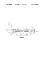
- FIG. 1is a system diagram illustrating a wireless communication device having a passive tag in accordance with the present invention, together with an RF controller for programming initial configuration information therein;
- FIG. 2is a front view of an exemplary mobile terminal in accordance with the present invention.
- FIG. 3is a side view of the mobile terminal shown in FIG. 2 ;
- FIG. 4is an electrical block diagram of a mobile terminal in accordance with the present invention.
- FIG. 5is an electrical block diagram of the passive tag included in a mobile terminal in accordance with the exemplary embodiment of the present invention.
- FIG. 6is an electrical block diagram of an access point in accordance with the present invention.
- a system for programming initial configuration information into a wireless communication deviceis generally designated 10 .
- the system 10includes a wireless communication device 12 (shown in phantom) such as a mobile terminal.
- the mobile terminal 12includes a passive tag 14 (also shown in phantom) which serves to receive and store initial configuration information used by the mobile terminal 12 to operate within a conventional wireless network.
- the mobile terminal 12 as shown in FIG. 1is enclosed in packaging 16 for sake of example.
- packaging 16may be any type of packaging such as cardboard, etc.; however the packaging 16 must be penetrable by an RF signal as will be appreciated.
- the mobile terminal 12 within the packaging 16may be stored on a shelf in a warehouse or the like as will be further appreciated.
- the system 10further includes an RF controller 18 which serves to transmit an RF signal used to program the initial configuration information into the mobile terminal 12 via the passive tag 14 .
- the RF controller 18includes a radio transmitter which transmits a signal at a frequency at which the passive tag 14 is tuned to receive. As will be described in more detail below in connection with FIGS. 4 and 5 , the passive tag 14 derives sufficient power from the RF signal to operate.
- the RF controller 18modulates the transmitted RF signal with the initial configuration information.
- the RF signalis transmitted through the packaging 16 and is received by the passive tag 14 .
- the passive tag 14demodulates the RF signal to obtain the initial configuration information and stores the same in a memory included therein.
- a processor within the mobile terminal 12accesses the initial configuration information stored in the memory so that the mobile terminal 12 may operate in the wireless network for which it is destined. In this manner, the mobile terminal 12 receives and stores the initial configuration information without requiring being removed from the packaging 16 , powered up, etc.
- the mobile terminal 12need not even be fully assembled at such time as the initial configuration information is provided thereto.
- the portion of the mobile terminal 12 including the passive tag 14may later be combined with any remaining portions of the mobile terminal in order to complete assembly.
- the initial configuration information stored in memory in the passive tag 14simply resides in memory until the mobile terminal 12 is assembled and powered up.
- the initial configuration information which is stored in the passive tag 14 via the RF controller 18may be of the type described above, e.g., device serial number, network identification, passwords, encryption keys, etc.
- the initial configuration datamay contain RF configuration data which allows the mobile terminal 12 to associate with a network access point and communicate within the network for which it is destined upon power up.
- the initial configurationmay also include instructions and a password for locating and communicating with an FTP server to download a software package.
- the FTP servermay be on the network of the customer in which the mobile terminal 12 is to be utilized. Alternatively, the FTP server may be controlled by the manufacturer.
- the mobile terminal 12accesses the manufacturer's FTP server via a gateway on the customer's network and the Internet, for example.
- the mobile terminal 12Upon being powered up, the mobile terminal 12 accesses the initial configuration information from the memory in the passive tag 14 and retrieves the instructions for locating the FTP server. The mobile terminal 12 then communicates with the FTP server (e.g., locally or via the Internet).
- the FTP servere.g., locally or via the Internet.
- FIG. 2illustrates an exemplary mobile terminal 12 including a passive tag 14 in accordance with the present invention.
- the mobile terminal 12includes a main housing 20 made of molded plastic or the like.
- the main housing 20preferably is sized to fit conveniently in the hand of an operator.
- Included within the main housing 20is a display 24 .
- the display 24may be a conventional liquid crystal display (LCD) such as an active matrix LCD or the like.
- the display 24may be an electroluminescent type display, etc.
- the mobile terminal 12further includes a keypad 26 having a plurality of different keys 30 arranged in a predefined configuration. Each key 30 includes thereon a label (not shown) indicative of the particular function of the key.
- the processor within the mobile terminal 12(discussed in more detail in connection with FIG. 4 ) is programmed to interpret a given key 30 in accordance with the particular function identified by the label or otherwise assigned to such key 30 . Each key 30 may be depressed by the operator in order to enter information and/or cause the mobile terminal 12 to perform a desired function.
- the mobile terminal 12also includes, for example, a bar code reader 32 which allows the operator to input information from bar code labels. Furthermore, the mobile terminal 12 includes an antenna 34 which allows the mobile terminal 12 to communicate wirelessly with a base station in a wireless network, for example. As will be discussed more fully with reference to FIG. 4 , the mobile terminal 12 in the exemplary embodiment includes a radio transceiver which permits the mobile terminal 12 to communicate wirelessly with other devices such as an access point in a wireless network.
- the mobile terminal 12includes a communication port 36 exposed through a wall of the main housing 20 .
- the communication port 36permits the mobile terminal 12 to communicate information and/or download software via a hardwired connection.
- the port 36may be any type of standard connector which allows the electronic circuitry within the mobile terminal 12 to communication with another device.
- the main housing 20 of the mobile terminal 12is made up of an upper portion 20 a and a lower portion 20 b , for example.
- the various components within the main housing 20are assembled within the respective portions 20 a and 20 b , and the two portions are then joined together to form an integral housing 20 .
- the portions 20 a and 20 bmay be fixed together via a set of screws, a snap fit, etc.
- the mobile terminal 12includes the passive tag 14 together with the other circuitry within the main housing 20 .
- the passive tag 14may be mounted on a circuit board with the other circuitry included in the mobile terminal.
- the passive tag 14may be mounted on an inside wall of the main housing 20 with cabling or the like providing the appropriate electrical connections to other components within the mobile terminal 12 .
- the particular location of the passive tag 14is not critical to the invention, although the passive tag 14 preferably is located in an area readily exposed to RF signals transmitted by the RF controller 18 (FIG. 1 ).
- the passive tag 14preferably is located at a place within the main housing 20 which includes an aperture to allow the RF signals to reach the passive tag 14 .
- FIG. 4illustrates the electronic circuitry included within the main housing 20 of the mobile terminal 12 .
- the mobile terminal 20is controlled primarily by a processor 40 .
- the processor 40executes instructions stored in a non-volatile memory 42 for carrying out the various intended operations of the mobile terminal 12 .
- the particular instructions stored in the memory 42may represent a program which is loaded into the mobile terminal 12 via the communication port 26 , for example.
- the processor 40uses the memory 42 to store data or other information which is collected via the mobile terminal 12 (e.g., inventory or patient information, depending on the particular application).
- the processor 40is connected to an ISA bus 44 or other conventional type bus.
- the display 24is coupled to the bus 44 via a display driver 46 .
- the processor 40is programmed to cause the display 24 to represent graphically to the operator appropriate display information during operation via the display driver 46 . Such operation is conventional, hence further detail is omitted for sake of brevity.
- the mobile terminal 12includes a radio transceiver 48 which permits the mobile terminal 12 to communicate wirelessly with other devices, such as a base station, using conventional techniques.
- the transceiver 48is coupled to the processor 40 via the bus 44 and a PCMCIA controller 50 as shown.
- the processor 40provides such information to the transceiver 48 via the bus 44 and the controller 50 .
- the transceiver 48in turn transmits the information as part of an RF signal to the other device using the antenna 34 .
- information which is transmitted to the mobile terminal 12 from another deviceis received by the transceiver 48 via the antenna 34 .
- the transceiver 48in turn provides the information to the processor 40 via the controller 50 and the bus 44 .
- the mobile terminal 12also includes an input/output (I/O) logic array 52 which provides conventional logic for receiving the respective input signals and output signals from the various I/O devices. Information to/from the communication port 36 and the barcode reader 32 is coupled to the processor 40 via the logic array 52 and the bus 44 using conventional techniques. Moreover, the mobile terminal 12 includes a battery based power supply 54 which provides the appropriate operating power to the various components within the mobile terminal 12 .
- I/Oinput/output
- the keypad 26is conventional in design.
- the keypad 26includes a keypad matrix 60 together with a column pulse circuit 62 and a row detector circuit 64 .
- the column pulse circuit 62provides pulses to columns in the matrix 60 and the row detector circuit 64 identifies the row in which a depressed key 30 exists.
- Both the column pulse circuit 62 and the row detector circuit 64are coupled to a decoder 66 which determines which key 30 has been depressed based on the outputs thereof.
- the decoder 66in turn provides such information to the processor 40 via the I/O logic array 52 .
- the passive tag 14includes a coil 70 which functions as an antenna for receiving electromagnetic signals from the RF controller 18 .
- the passive tag 14includes within a circuit 72 a demodulator and decoder which demodulates and decodes the modulated RF signal received from the RF controller 18 .
- the resultant signalrepresents initial configuration information which is stored in memory in the circuit 72 .
- Data which is stored in memory in the circuit 72is coupled to the processor 40 via an interface 74 on a command/data bus 76 .
- Address informationis provided by the processor 40 to the memory within the circuit 72 via the interface 74 and an address bus 78 .
- the processor 40provides an ACT control signal to the circuit 72 on line 80 .
- the ACT signalis used to switch the memory within the circuit 72 from a passive mode to an active mode when the mobile terminal 12 is powered up. More specifically, the mobile terminal 12 is configured such that when it is powered up (e.g., via the battery power 54 ) in order to be operational, the ACT signal goes active. This causes power from the battery power 54 to be supplied to the circuit 72 via line 82 as discussed below in relation to FIG. 5 .
- the interface 74is provided to perform any voltage conversion, line or data buffering, data conversion which may be necessary depending on the particular type of processor 40 and memory within the circuit 72 .
- the general principles, however,are the same and hence operation of the circuit will be described as if the interface was not present.
- FIG. 5illustrates the exemplary embodiment of the passive tag 14 in more detail.
- the passive tag 14is represented in substantial part by the passive tag described in U.S. Pat. No. 5,517,194, entitled “Passive RF Transponder and Method”, issued May 14, 1996. The entire disclosure of U.S. Pat. No. 5,517,194 is incorporated herein by reference.
- the passive tag 14includes the aforementioned coil 70 for receiving the RF signals transmitted by the RF controller 18 .
- the received signalsare input to a demodulation/decoder/power block 90 included in the circuit 72 .
- the block 90includes circuitry for demodulating and decoding the received signal in order to obtain data such as the initial configuration information which had been modulated onto the RF signal by the controller 18 .
- the electrical power for carrying out such functionsis derived from the energy of the RF signal itself as described in the aforementioned '194 patent.
- Address information which determines where the received initial configuration information is stored in memoryis output from the block 90 on line 92 .
- the data representing the received initial configuration information itselfis output from the block 90 on line 94 .
- Electrical power for operating the passive tag 14 when in the passive modeis derived from the RF signal by the block 90 and is output on line 96 .
- the passive tag 14further includes the aforementioned memory 98 , an address register 100 , and a command/data register 102 . While the tag 14 is in the passive mode (i.e., the ACT signal is non-active), address information provided by the block 90 on line 92 is input to the address register 100 which is coupled to the address input of the memory 98 . The address in the address register 100 determines the particular location(s) in the memory 98 in which the initial configuration information is stored upon receipt of the RF signal from the RF controller 18 . Also while the tag 14 is in the passive mode, the initial configuration information obtained from the received RF signal is provided by the block 90 on line 94 and is input to the command/data register 102 . The command/data register 102 is coupled to the data port of the memory 98 so that the data in the register 102 is stored in the memory 98 .
- the circuit 72includes switches 104 a , 104 b and 104 c .
- Switch 104 aserves to switch selectively either the address information from block 90 on line 92 or address information provided by the processor 40 on line 78 to the input of the address register 100 .
- Switch 104 bserves to switch selectively either line 94 from block 90 or line 76 from the processor 40 to the command/data register 102 .
- switch 104 cthis switch controls whether the operating power for the passive tag 14 comes from the RF derived power on line 96 or from line 82 .
- the ACT signalis designed to be non-active and the switches 104 a thru 104 c are in the positions shown in FIG. 5 .
- the mobile terminal 12is likely within its packaging, powered down, and/or unassembled, etc., and is in need of receiving initial configuration information.
- the RF controller 18( FIG. 1 ) is configured to operate in a manner similar to that described in the aforementioned U.S. Pat. No. 5,517,194. In particular, the RF controller 18 is configured to transmit the RF signal to the passive tag 14 with the initial configuration information modulated therein.
- the coil 70receives the RF signal and derives power for operating the passive tag 14 from the RF signal.
- Block 90functions to demodulate and decode the initial configuration information from the RF signal and places information in the form of digital data onto line 94 . At the same time, block 90 provides appropriate addressing onto line 92 .
- the addressing on line 92is coupled to the address register 100 via the switch 104 a .
- the initial configuration informationis coupled into the command/data register 102 via the switch 104 b .
- the initial configuration informationis stored in the nonvolatile memory 98 .
- Power derived from the RF signal on line 96is provided to the various components within the passive tag 14 via the switch 104 c.
- the processor 40 within the mobile terminal 12When powered up, the processor 40 within the mobile terminal 12 causes the ACT signal to become and remain active. This causes the switch 104 a to allow for address information provided on line 78 from the processor 40 to be input to the address register 100 . Similarly, the switch 104 b allows data accessed from the memory 98 to be provided to the processor 40 via the command/data register 102 and line 76 . The switch 104 c causes operating power from the supply 54 to be provided to the passive tag 14 .
- the processor 40is programmed as part of an initialization routine and/or general operation to access the information in the memory 98 upon being powered up in order to permit the mobile terminal 12 to carry out its intended functions. For example, upon initially being powered up the processor 40 is programmed to access the location in the memory 98 in which the network address or network identification of the mobile terminal 12 is to have been stored by the RF controller 18 . In addition, or in the alternative, the processor 40 may retrieve one or more flags which have previously been stored in the memory 98 by the controller 18 to define prescribed operating parameters. As will be appreciated, there is a wide variety of types of initial configuration information which may be stored and retrieved from the memory 98 in accordance with the present invention.
- FIG. 6illustrates how the inventive features of the mobile terminal 12 in FIG. 4 can be extended to other wireless communication devices such as an access point 150 . Operation is substantially similar to that described above in relation to the mobile terminal 12 , with the exception that the passive tag 14 is coupled to the processor and power supply of a standard access point circuit 152 rather than a mobile terminal circuit.
- the embodiments described aboveutilize generally a single port memory which selectively receives the signal from the block 90 or the processor 40 via the set of switches 104 a thru 104 c .
- a dual-port memorycan be used in place of the memory 98 .
- a first portis coupled to the block 90 for receiving the initial configuration information from the modulated RF signal.
- a second portis coupled to the processor 40 which enables the processor to access the initial configuration information from the memory when the device is powered up.
- the present inventionprovides a means by which wireless communication devices can be initially configured without requiring full assembly and/or operation. This can significantly reduce the time and/or cost associated with programming the initial configuration information into the devices.
Landscapes
- Engineering & Computer Science (AREA)
- Computer Networks & Wireless Communication (AREA)
- Signal Processing (AREA)
- Mobile Radio Communication Systems (AREA)
Abstract
Description
Claims (6)
Priority Applications (2)
| Application Number | Priority Date | Filing Date | Title |
|---|---|---|---|
| US09/212,833US6876295B1 (en) | 1998-12-16 | 1998-12-16 | Wireless communication devices configurable via passive tags |
| US10/947,870US7106175B2 (en) | 1998-12-16 | 2004-09-23 | Wireless communication devices configurable via passive tags |
Applications Claiming Priority (1)
| Application Number | Priority Date | Filing Date | Title |
|---|---|---|---|
| US09/212,833US6876295B1 (en) | 1998-12-16 | 1998-12-16 | Wireless communication devices configurable via passive tags |
Related Child Applications (1)
| Application Number | Title | Priority Date | Filing Date |
|---|---|---|---|
| US10/947,870ContinuationUS7106175B2 (en) | 1998-12-16 | 2004-09-23 | Wireless communication devices configurable via passive tags |
Publications (1)
| Publication Number | Publication Date |
|---|---|
| US6876295B1true US6876295B1 (en) | 2005-04-05 |
Family
ID=34134897
Family Applications (2)
| Application Number | Title | Priority Date | Filing Date |
|---|---|---|---|
| US09/212,833Expired - LifetimeUS6876295B1 (en) | 1998-12-16 | 1998-12-16 | Wireless communication devices configurable via passive tags |
| US10/947,870Expired - Fee RelatedUS7106175B2 (en) | 1998-12-16 | 2004-09-23 | Wireless communication devices configurable via passive tags |
Family Applications After (1)
| Application Number | Title | Priority Date | Filing Date |
|---|---|---|---|
| US10/947,870Expired - Fee RelatedUS7106175B2 (en) | 1998-12-16 | 2004-09-23 | Wireless communication devices configurable via passive tags |
Country Status (1)
| Country | Link |
|---|---|
| US (2) | US6876295B1 (en) |
Cited By (44)
| Publication number | Priority date | Publication date | Assignee | Title |
|---|---|---|---|---|
| US20020099804A1 (en)* | 2001-01-25 | 2002-07-25 | O'connor Clint H. | Method and system for configuring a computer system via a wireless communication link |
| US20030103464A1 (en)* | 2001-11-30 | 2003-06-05 | Palm Inc. | Network connectivity system and method |
| US20050145688A1 (en)* | 2003-12-29 | 2005-07-07 | Milan Milenkovic | Asset management methods and apparatus |
| US20050251798A1 (en)* | 2004-05-05 | 2005-11-10 | News, Iq, Inc. | System and method for inventory control and management |
| US20050272371A1 (en)* | 2002-04-25 | 2005-12-08 | Yoriko Komatsuzaki | Communication system, information processing device, and method |
| US20060028319A1 (en)* | 2004-08-04 | 2006-02-09 | First Data Corporation | Radio-frequency-device personalization |
| US20060142876A1 (en)* | 2002-12-19 | 2006-06-29 | Phoenix Contact Gmbh & Co. Kg | Location-specific adaptation of an intelligent unit |
| US20060219462A1 (en)* | 2003-01-09 | 2006-10-05 | Gerd Martin | Forward frame part for a utility vehicle |
| US7256681B1 (en)* | 2000-10-20 | 2007-08-14 | Lockheed Martin Corporation | Asset tracking using wireless LAN infrastructure |
| US20080041930A1 (en)* | 2006-08-17 | 2008-02-21 | Smith Joshua R | Device configuration with RFID |
| US20080048837A1 (en)* | 2006-07-18 | 2008-02-28 | Hewlett-Packard Development Company Lp | RF tag |
| US20080048838A1 (en)* | 2006-07-18 | 2008-02-28 | Hewlett-Packard Development Company Lp | Code upgrade |
| US20080068136A1 (en)* | 2006-08-31 | 2008-03-20 | Symbol Technologies, Inc. | Methods and apparatus for autoconfiguration of RFID readers |
| US20080303640A1 (en)* | 2007-06-05 | 2008-12-11 | Heiko Rommelmann | Hybrid system option key |
| US20090072973A1 (en)* | 2007-09-19 | 2009-03-19 | Chung Shan Institute Of Science And Technology, Armaments Bureau, M.N.D. | Physical audit system with radio frequency identification and method thereof |
| US20090224894A1 (en)* | 2006-08-31 | 2009-09-10 | Huawei Technologies Co., Ltd. | Method and system for device configuring |
| US20100156639A1 (en)* | 2008-12-18 | 2010-06-24 | Nathaniel Christopher Herwig | Device configuration system and method |
| US20100274930A1 (en)* | 2009-04-28 | 2010-10-28 | Samir Thakkar | Method for generically handling carrier specific provisioning for computer cellular wireless cards |
| US20100291898A1 (en)* | 2009-05-17 | 2010-11-18 | Anthony Sanding | Method and apparatus for programming a mobile device with multiple service accounts |
| US20100291910A1 (en)* | 2009-05-17 | 2010-11-18 | Anthony Sanding | Method and apparatus for tracking the programming of a mobile device with multiple service accounts |
| US7880590B2 (en) | 2006-07-18 | 2011-02-01 | Hewlett-Packard Development Company, L.P. | Method and apparatus for localization of configurable devices |
| US20110102148A1 (en)* | 2009-10-29 | 2011-05-05 | Laffey Thomas M | Configuration information provided to configurable electronic device residing in a shipping box |
| US20110175734A1 (en)* | 2002-07-09 | 2011-07-21 | Frederick Sawyer | Method and apparatus for tracking objects and people |
| US20110241844A1 (en)* | 2010-03-30 | 2011-10-06 | Bsh Home Appliances Corporation | Appliance including a radio frequency identification (rfid) device and method for two-way communication of dynamic data by the appliance via the rfid device |
| CN101562821B (en)* | 2008-04-16 | 2012-01-04 | 北京信威通信技术股份有限公司 | Method for ensuring stability of service transmission in wireless communication system |
| US20120044060A1 (en)* | 2010-08-17 | 2012-02-23 | Seiko Epson Corporation | Electronic Device And Data Management System |
| US20120306621A1 (en)* | 2011-06-03 | 2012-12-06 | Leviton Manufacturing Co., Inc. | Lighting control network configuration with rfid devices |
| EP2506115A3 (en)* | 2011-04-01 | 2013-11-13 | Honeywell International Inc. | Devices that receive data while not directly powered |
| US8756256B2 (en) | 2010-05-26 | 2014-06-17 | Qualcomm Incorporated | Method and systems for the management of non volatile items and provisioning files for a communication device with multiple service accounts |
| US8866581B1 (en) | 2010-03-09 | 2014-10-21 | Amazon Technologies, Inc. | Securing content using a wireless authentication factor |
| US9188976B1 (en)* | 2009-09-02 | 2015-11-17 | Amazon Technologies, Inc. | Content enabling cover for electronic book reader devices |
| US9241237B2 (en) | 2006-08-15 | 2016-01-19 | Nxp B.V. | Device with an EEPROM having both a near field communication interface and a second interface |
| US9854651B2 (en)* | 2013-08-19 | 2017-12-26 | Philips Lighting Holding B.V. | Programmable lighting device and method and system for programming lighting device |
| US9864594B1 (en)* | 2014-09-30 | 2018-01-09 | Amazon Technologies, Inc. | Software upgrade and operation testing of a packaged electronic device |
| US10050444B2 (en) | 2012-12-21 | 2018-08-14 | Lutron Electronics Co., Inc. | Network access coordination of load control devices |
| US10135629B2 (en) | 2013-03-15 | 2018-11-20 | Lutron Electronics Co., Inc. | Load control device user interface and database management using near field communication (NFC) |
| US10244086B2 (en) | 2012-12-21 | 2019-03-26 | Lutron Electronics Co., Inc. | Multiple network access load control devices |
| US10271407B2 (en) | 2011-06-30 | 2019-04-23 | Lutron Electronics Co., Inc. | Load control device having Internet connectivity |
| US10367582B2 (en) | 2011-06-30 | 2019-07-30 | Lutron Technology Company Llc | Method of optically transmitting digital information from a smart phone to a control device |
| US10373036B2 (en)* | 2015-04-01 | 2019-08-06 | Daikin Industries, Ltd. | Remote control for air conditioner and air conditioner provided with same |
| US10587147B2 (en) | 2011-08-29 | 2020-03-10 | Lutron Technology Company Llc | Two-part load control system mountable to a single electrical wallbox |
| US10779381B2 (en) | 2011-06-30 | 2020-09-15 | Lutron Technology Company Llc | Method of programming a load control device |
| EP2999314B1 (en) | 2006-06-02 | 2020-11-18 | Signify Holding B.V. | Lamp control circuit and method of driving a lamp |
| US11301013B2 (en) | 2012-12-21 | 2022-04-12 | Lutron Technology Company, LLC | Operational coordination of load control devices for control of electrical loads |
Families Citing this family (31)
| Publication number | Priority date | Publication date | Assignee | Title |
|---|---|---|---|---|
| GB2362070B (en)* | 2000-05-05 | 2004-06-16 | Nokia Mobile Phones Ltd | Communication devices and method of communication |
| JP3707410B2 (en)* | 2001-09-17 | 2005-10-19 | インターナショナル・ビジネス・マシーンズ・コーポレーション | Computer apparatus, expansion device management method, and computer program |
| CA2533029C (en)* | 2003-07-22 | 2014-06-03 | Nokia Corporation | Reader device for radio frequency identification transponder with transponder functionality |
| WO2005081183A1 (en) | 2004-01-23 | 2005-09-01 | Nokia Corporation | Method, device and system for automated context information based selective data provision by identification means |
| ATE435469T1 (en)* | 2004-03-17 | 2009-07-15 | Nokia Corp | CONTINUOUS DATA PROVISION THROUGH HIGH FREQUENCY IDENTIFICATION (RFID) TRANSPONDER |
| CN1918585B (en) | 2004-03-19 | 2010-05-05 | 诺基亚公司 | Detector logic and radio identification device and method for enhanced terminal operation |
| CA2587912A1 (en)* | 2004-11-19 | 2006-05-26 | Sensormatic Electronics Corporation | Technique and hardware for communicating with backscatter radio frequency identification readers |
| US7398379B1 (en)* | 2005-05-02 | 2008-07-08 | Altera Corporation | Programmable logic device integrated circuits with wireless programming |
| US8718554B2 (en)* | 2006-02-15 | 2014-05-06 | Microsoft Corporation | Means for provisioning and managing mobile device configuration over a near-field communication link |
| DE102006050527A1 (en)* | 2006-10-26 | 2008-04-30 | Conti Temic Microelectronic Gmbh | Electrical energy and/or information introducing method for e.g. accumulator, involves converting electromagnetic energy and information into electrical energy and digital or analog signal and introducing energy and signal into component |
| ITGE20060117A1 (en)* | 2006-11-29 | 2008-05-30 | Montalbano Technology S P A | INTEGRATED SOLUTION FOR SENSOR INTERFACE FOR MONITORING ENVIRONMENTAL DIVISIONS THROUGH RFID TECHNOLOGIES (RADIO FREQUENCY IDENTIFICATION) |
| US8098160B2 (en)* | 2007-01-22 | 2012-01-17 | Cisco Technology, Inc. | Method and system for remotely provisioning and/or configuring a device |
| US8004409B2 (en) | 2007-02-13 | 2011-08-23 | Physical Optics Corporation | Wireless personal information carrier having logic for connecting a battery only during data transfers |
| EP1968241A1 (en)* | 2007-03-06 | 2008-09-10 | Koninklijke KPN N.V. | Method for gaining access to a comunication network, and a communication system |
| EP2280580A1 (en)* | 2009-07-07 | 2011-02-02 | Nokia Corporation | Data transfer with wirelessly powered communication devices |
| US9076091B2 (en)* | 2010-03-10 | 2015-07-07 | Apple Inc. | RFID circuitry and methods of using the same to provide information of events pertaining to an electronic device |
| US9916169B2 (en)* | 2011-04-15 | 2018-03-13 | Polycom, Inc. | System and method for in-box electronic device provisioning |
| US8671171B2 (en) | 2011-12-01 | 2014-03-11 | International Business Machines Corporation | Wireless configuration for a computing device |
| US8849708B2 (en)* | 2012-12-14 | 2014-09-30 | Amazon Technologies, Inc. | Device customization during order fulfillment utilizing an embedded electronic tag |
| DE102013205896A1 (en)* | 2013-04-03 | 2014-10-09 | Lenze Drives Gmbh | Electric control unit and RFID read / write device |
| KR102051369B1 (en)* | 2013-04-09 | 2019-12-03 | 엘지전자 주식회사 | A Home Appliance, System AND A Controlling Method for A Home Appliance |
| US10560975B2 (en) | 2014-04-16 | 2020-02-11 | Belkin International, Inc. | Discovery of connected devices to determine control capabilities and meta-information |
| US10314088B2 (en)* | 2014-04-16 | 2019-06-04 | Belkin International, Inc. | Associating devices and users with a local area network using network identifiers |
| FR3023097A1 (en)* | 2014-06-27 | 2016-01-01 | Orange | METHOD FOR CONFIGURING A COMMUNICATION DEVICE |
| JP2016045686A (en)* | 2014-08-22 | 2016-04-04 | アズビル株式会社 | Controller |
| KR20170100473A (en)* | 2014-09-18 | 2017-09-04 | 부즈 알렌 해밀톤 인코포레이티드 | System and method for location-based security |
| US10819395B1 (en) | 2014-09-24 | 2020-10-27 | Amazon Technologies, Inc. | Inductance powered packaging to configure a device |
| DE102016224158A1 (en)* | 2016-12-05 | 2018-06-07 | Continental Automotive Gmbh | Method for configuring devices and corresponding devices |
| US9841490B1 (en) | 2017-01-17 | 2017-12-12 | Booz Allen Hamilton Inc. | System and method for detecting movement of a mobile asset and controlling operations of the asset based on its movement |
| US10061933B1 (en) | 2018-01-09 | 2018-08-28 | Booz Allen Hamilton Inc. | System and method for controlling the power states of a mobile computing device |
| GB2594253A (en)* | 2020-04-20 | 2021-10-27 | Eaton Intelligent Power Ltd | Communication card, arrangement with communication card, box and bundle box |
Citations (13)
| Publication number | Priority date | Publication date | Assignee | Title |
|---|---|---|---|---|
| US4827395A (en)* | 1983-04-21 | 1989-05-02 | Intelli-Tech Corporation | Manufacturing monitoring and control systems |
| US5394367A (en) | 1994-03-18 | 1995-02-28 | Ramtron International Corporation | System and method for write-protecting predetermined portions of a memory array |
| US5465401A (en)* | 1992-12-15 | 1995-11-07 | Texas Instruments Incorporated | Communication system and methods for enhanced information transfer |
| US5517194A (en) | 1994-02-10 | 1996-05-14 | Racom Systems, Inc. | Passive RF transponder and method |
| US5539394A (en)* | 1994-03-16 | 1996-07-23 | International Business Machines Corporation | Time division multiplexed batch mode item identification system |
| WO1997011446A1 (en) | 1995-09-19 | 1997-03-27 | Steven Derek Pike | Device and method for simulating hazardous material detection |
| US5682143A (en) | 1994-09-09 | 1997-10-28 | International Business Machines Corporation | Radio frequency identification tag |
| US5776278A (en) | 1992-06-17 | 1998-07-07 | Micron Communications, Inc. | Method of manufacturing an enclosed transceiver |
| US5787174A (en) | 1992-06-17 | 1998-07-28 | Micron Technology, Inc. | Remote identification of integrated circuit |
| US5848064A (en)* | 1996-08-07 | 1998-12-08 | Telxon Corporation | Wireless software upgrades with version control |
| US6046676A (en)* | 1997-11-14 | 2000-04-04 | International Business Machines Corporation | Self powered electronic memory identification tag with dual communication ports |
| US6064649A (en)* | 1997-01-31 | 2000-05-16 | Nec Usa, Inc. | Network interface card for wireless asynchronous transfer mode networks |
| US6177860B1 (en)* | 1997-11-17 | 2001-01-23 | International Business Machines Corporation | Method and economical direct connected apparatus for deploying and tracking computers |
Family Cites Families (2)
| Publication number | Priority date | Publication date | Assignee | Title |
|---|---|---|---|---|
| US5764138A (en)* | 1994-04-29 | 1998-06-09 | Hid Corporation | RF identification system for providing static data and one bit of variable data representative of an external stimulus |
| US6778096B1 (en)* | 1997-11-17 | 2004-08-17 | International Business Machines Corporation | Method and apparatus for deploying and tracking computers |
- 1998
- 1998-12-16USUS09/212,833patent/US6876295B1/ennot_activeExpired - Lifetime
- 2004
- 2004-09-23USUS10/947,870patent/US7106175B2/ennot_activeExpired - Fee Related
Patent Citations (13)
| Publication number | Priority date | Publication date | Assignee | Title |
|---|---|---|---|---|
| US4827395A (en)* | 1983-04-21 | 1989-05-02 | Intelli-Tech Corporation | Manufacturing monitoring and control systems |
| US5776278A (en) | 1992-06-17 | 1998-07-07 | Micron Communications, Inc. | Method of manufacturing an enclosed transceiver |
| US5787174A (en) | 1992-06-17 | 1998-07-28 | Micron Technology, Inc. | Remote identification of integrated circuit |
| US5465401A (en)* | 1992-12-15 | 1995-11-07 | Texas Instruments Incorporated | Communication system and methods for enhanced information transfer |
| US5517194A (en) | 1994-02-10 | 1996-05-14 | Racom Systems, Inc. | Passive RF transponder and method |
| US5539394A (en)* | 1994-03-16 | 1996-07-23 | International Business Machines Corporation | Time division multiplexed batch mode item identification system |
| US5394367A (en) | 1994-03-18 | 1995-02-28 | Ramtron International Corporation | System and method for write-protecting predetermined portions of a memory array |
| US5682143A (en) | 1994-09-09 | 1997-10-28 | International Business Machines Corporation | Radio frequency identification tag |
| WO1997011446A1 (en) | 1995-09-19 | 1997-03-27 | Steven Derek Pike | Device and method for simulating hazardous material detection |
| US5848064A (en)* | 1996-08-07 | 1998-12-08 | Telxon Corporation | Wireless software upgrades with version control |
| US6064649A (en)* | 1997-01-31 | 2000-05-16 | Nec Usa, Inc. | Network interface card for wireless asynchronous transfer mode networks |
| US6046676A (en)* | 1997-11-14 | 2000-04-04 | International Business Machines Corporation | Self powered electronic memory identification tag with dual communication ports |
| US6177860B1 (en)* | 1997-11-17 | 2001-01-23 | International Business Machines Corporation | Method and economical direct connected apparatus for deploying and tracking computers |
Cited By (91)
| Publication number | Priority date | Publication date | Assignee | Title |
|---|---|---|---|---|
| US7256681B1 (en)* | 2000-10-20 | 2007-08-14 | Lockheed Martin Corporation | Asset tracking using wireless LAN infrastructure |
| US7149884B2 (en)* | 2001-01-25 | 2006-12-12 | Dell Products L.P. | Method and system for configuring a computer system via a wireless communication link |
| US20020099804A1 (en)* | 2001-01-25 | 2002-07-25 | O'connor Clint H. | Method and system for configuring a computer system via a wireless communication link |
| US20030103464A1 (en)* | 2001-11-30 | 2003-06-05 | Palm Inc. | Network connectivity system and method |
| US20070019602A1 (en)* | 2001-11-30 | 2007-01-25 | Palm, Inc | Network connectivity system and method |
| US7072326B2 (en)* | 2001-11-30 | 2006-07-04 | Palm, Inc. | Network connectivity system and method |
| US7565107B2 (en)* | 2002-04-25 | 2009-07-21 | Sony Corporation | Communication system, information processing device, and method |
| US20050272371A1 (en)* | 2002-04-25 | 2005-12-08 | Yoriko Komatsuzaki | Communication system, information processing device, and method |
| US8742929B2 (en) | 2002-07-09 | 2014-06-03 | Automated Tracking Solutions, Llc | Method and apparatus for tracking objects and people |
| US10496859B2 (en) | 2002-07-09 | 2019-12-03 | Automated Tracking Solutions, Llc | Method and apparatus for tracking objects and people |
| US10152620B2 (en) | 2002-07-09 | 2018-12-11 | Automated Tracking Solutions, Llc | Method and apparatus for tracking objects and people |
| US9619679B2 (en) | 2002-07-09 | 2017-04-11 | Automated Tracking Solutions, Llc | Method and apparatus for tracking objects and people |
| US8896449B2 (en) | 2002-07-09 | 2014-11-25 | Automated Tracking Solutions, Llc | Method and apparatus for tracking objects and people |
| US20110175734A1 (en)* | 2002-07-09 | 2011-07-21 | Frederick Sawyer | Method and apparatus for tracking objects and people |
| US8842013B2 (en) | 2002-07-09 | 2014-09-23 | Automated Tracking Solutions, Llc | Method and apparatus for tracking objects and people |
| US8866615B2 (en) | 2002-07-09 | 2014-10-21 | Automated Tracking Solutions, Llc | Method and apparatus for tracking objects and people |
| US8279069B2 (en) | 2002-07-09 | 2012-10-02 | Automated Tracking Solutions, Llc | Method and apparatus for tracking objects and people |
| US20060142876A1 (en)* | 2002-12-19 | 2006-06-29 | Phoenix Contact Gmbh & Co. Kg | Location-specific adaptation of an intelligent unit |
| US20060219462A1 (en)* | 2003-01-09 | 2006-10-05 | Gerd Martin | Forward frame part for a utility vehicle |
| US7180422B2 (en)* | 2003-12-29 | 2007-02-20 | Intel Corporation | Asset management methods and apparatus |
| US20050145688A1 (en)* | 2003-12-29 | 2005-07-07 | Milan Milenkovic | Asset management methods and apparatus |
| US20050251798A1 (en)* | 2004-05-05 | 2005-11-10 | News, Iq, Inc. | System and method for inventory control and management |
| US20090179744A1 (en)* | 2004-08-04 | 2009-07-16 | First Data Corporation | Radio-frequency-device personalization |
| US7482908B2 (en)* | 2004-08-04 | 2009-01-27 | First Data Coporation | Radio-frequency-device personalization |
| US20060028319A1 (en)* | 2004-08-04 | 2006-02-09 | First Data Corporation | Radio-frequency-device personalization |
| EP2999314B1 (en) | 2006-06-02 | 2020-11-18 | Signify Holding B.V. | Lamp control circuit and method of driving a lamp |
| US20080048838A1 (en)* | 2006-07-18 | 2008-02-28 | Hewlett-Packard Development Company Lp | Code upgrade |
| US7852198B2 (en)* | 2006-07-18 | 2010-12-14 | Hewlett-Packard Development Company, L.P. | RF tag |
| US7880590B2 (en) | 2006-07-18 | 2011-02-01 | Hewlett-Packard Development Company, L.P. | Method and apparatus for localization of configurable devices |
| US20080048837A1 (en)* | 2006-07-18 | 2008-02-28 | Hewlett-Packard Development Company Lp | RF tag |
| US9241237B2 (en) | 2006-08-15 | 2016-01-19 | Nxp B.V. | Device with an EEPROM having both a near field communication interface and a second interface |
| US7825776B2 (en)* | 2006-08-17 | 2010-11-02 | Intel Corporation | Device configuration with RFID |
| US20080041930A1 (en)* | 2006-08-17 | 2008-02-21 | Smith Joshua R | Device configuration with RFID |
| US20090224894A1 (en)* | 2006-08-31 | 2009-09-10 | Huawei Technologies Co., Ltd. | Method and system for device configuring |
| US20080068136A1 (en)* | 2006-08-31 | 2008-03-20 | Symbol Technologies, Inc. | Methods and apparatus for autoconfiguration of RFID readers |
| US20080303640A1 (en)* | 2007-06-05 | 2008-12-11 | Heiko Rommelmann | Hybrid system option key |
| US7902964B2 (en)* | 2007-06-05 | 2011-03-08 | Xerox Corporation | Hybrid system option key |
| US20090072973A1 (en)* | 2007-09-19 | 2009-03-19 | Chung Shan Institute Of Science And Technology, Armaments Bureau, M.N.D. | Physical audit system with radio frequency identification and method thereof |
| US8164453B2 (en)* | 2007-09-19 | 2012-04-24 | Chung Shan Institute Of Science And Technology, Armaments Bureau, M.N.D. | Physical audit system with radio frequency identification and method thereof |
| CN101562821B (en)* | 2008-04-16 | 2012-01-04 | 北京信威通信技术股份有限公司 | Method for ensuring stability of service transmission in wireless communication system |
| US20100156639A1 (en)* | 2008-12-18 | 2010-06-24 | Nathaniel Christopher Herwig | Device configuration system and method |
| US8453140B2 (en)* | 2009-04-28 | 2013-05-28 | Qualcomm Incorporated | Method for generically handling carrier specific provisioning for computer cellular wireless cards |
| US20100274930A1 (en)* | 2009-04-28 | 2010-10-28 | Samir Thakkar | Method for generically handling carrier specific provisioning for computer cellular wireless cards |
| US20100291898A1 (en)* | 2009-05-17 | 2010-11-18 | Anthony Sanding | Method and apparatus for programming a mobile device with multiple service accounts |
| US8417231B2 (en) | 2009-05-17 | 2013-04-09 | Qualcomm Incorporated | Method and apparatus for programming a mobile device with multiple service accounts |
| US8417234B2 (en) | 2009-05-17 | 2013-04-09 | Qualcomm Incorporated | Method and apparatus for tracking the programming of a mobile device with multiple service accounts |
| US20100291910A1 (en)* | 2009-05-17 | 2010-11-18 | Anthony Sanding | Method and apparatus for tracking the programming of a mobile device with multiple service accounts |
| US9188976B1 (en)* | 2009-09-02 | 2015-11-17 | Amazon Technologies, Inc. | Content enabling cover for electronic book reader devices |
| US8477045B2 (en)* | 2009-10-29 | 2013-07-02 | Hewlett-Packard Development Company, L.P. | Configuration information provided to configurable electronic device residing in a shipping box |
| US20110102148A1 (en)* | 2009-10-29 | 2011-05-05 | Laffey Thomas M | Configuration information provided to configurable electronic device residing in a shipping box |
| US8866581B1 (en) | 2010-03-09 | 2014-10-21 | Amazon Technologies, Inc. | Securing content using a wireless authentication factor |
| US9560045B1 (en) | 2010-03-09 | 2017-01-31 | Amazon Technologies, Inc. | Securing content using a wireless authentication factor |
| US20110241844A1 (en)* | 2010-03-30 | 2011-10-06 | Bsh Home Appliances Corporation | Appliance including a radio frequency identification (rfid) device and method for two-way communication of dynamic data by the appliance via the rfid device |
| US8756256B2 (en) | 2010-05-26 | 2014-06-17 | Qualcomm Incorporated | Method and systems for the management of non volatile items and provisioning files for a communication device with multiple service accounts |
| US20120044060A1 (en)* | 2010-08-17 | 2012-02-23 | Seiko Epson Corporation | Electronic Device And Data Management System |
| EP2506115A3 (en)* | 2011-04-01 | 2013-11-13 | Honeywell International Inc. | Devices that receive data while not directly powered |
| US8892854B2 (en)* | 2011-04-01 | 2014-11-18 | Honeywell International Inc. | Devices that receive data while not directly powered |
| US20120306621A1 (en)* | 2011-06-03 | 2012-12-06 | Leviton Manufacturing Co., Inc. | Lighting control network configuration with rfid devices |
| US11765809B2 (en) | 2011-06-30 | 2023-09-19 | Lutron Technology Company Llc | Load control device having internet connectivity |
| US12075321B2 (en) | 2011-06-30 | 2024-08-27 | Lutron Technology Company Llc | Method of programming a load control device |
| US12317162B2 (en) | 2011-06-30 | 2025-05-27 | Lutron Technology Company Llc | Method of programming a load control device |
| US10271407B2 (en) | 2011-06-30 | 2019-04-23 | Lutron Electronics Co., Inc. | Load control device having Internet connectivity |
| US10367582B2 (en) | 2011-06-30 | 2019-07-30 | Lutron Technology Company Llc | Method of optically transmitting digital information from a smart phone to a control device |
| US12144082B2 (en) | 2011-06-30 | 2024-11-12 | Lutron Technology Company Llc | Load control device having internet connectivity |
| US12089318B2 (en) | 2011-06-30 | 2024-09-10 | Lutron Technology Company Llc | Method of optically transmitting digital information from a smart phone to a control device |
| US11388570B2 (en) | 2011-06-30 | 2022-07-12 | Lutron Technology Company Llc | Method of programming a load control device |
| US10779381B2 (en) | 2011-06-30 | 2020-09-15 | Lutron Technology Company Llc | Method of programming a load control device |
| US10588204B2 (en) | 2011-06-30 | 2020-03-10 | Lutron Technology Company Llc | Load control device having internet connectivity |
| US11412603B2 (en) | 2011-06-30 | 2022-08-09 | Lutron Technology Company Llc | Method of optically transmitting digital information from a smart phone to a control device |
| US10693558B2 (en) | 2011-06-30 | 2020-06-23 | Lutron Technology Company Llc | Method of optically transmitting digital information from a smart phone to a control device |
| US10587147B2 (en) | 2011-08-29 | 2020-03-10 | Lutron Technology Company Llc | Two-part load control system mountable to a single electrical wallbox |
| US11889604B2 (en) | 2011-08-29 | 2024-01-30 | Lutron Technology Company, LLC | Two-part load control system mountable to a single electrical wallbox |
| US11229105B2 (en) | 2011-08-29 | 2022-01-18 | Lutron Technology Company Llc | Two-part load control system mountable to a single electrical wallbox |
| US12052331B2 (en) | 2012-12-21 | 2024-07-30 | Lutron Technology Company Llc | Multiple network access load control devices |
| US10050444B2 (en) | 2012-12-21 | 2018-08-14 | Lutron Electronics Co., Inc. | Network access coordination of load control devices |
| US12412467B2 (en) | 2012-12-21 | 2025-09-09 | Lutron Technology Company Llc | Network access coordination of load control devices |
| US11301013B2 (en) | 2012-12-21 | 2022-04-12 | Lutron Technology Company, LLC | Operational coordination of load control devices for control of electrical loads |
| US12368791B2 (en) | 2012-12-21 | 2025-07-22 | Lutron Technology Company Llc | Multiple network access load control devices |
| US10742032B2 (en) | 2012-12-21 | 2020-08-11 | Lutron Technology Company Llc | Network access coordination of load control devices |
| US11470187B2 (en) | 2012-12-21 | 2022-10-11 | Lutron Technology Company Llc | Multiple network access load control devices |
| US11521482B2 (en) | 2012-12-21 | 2022-12-06 | Lutron Technology Company Llc | Network access coordination of load control devices |
| US10244086B2 (en) | 2012-12-21 | 2019-03-26 | Lutron Electronics Co., Inc. | Multiple network access load control devices |
| US12282367B2 (en) | 2012-12-21 | 2025-04-22 | Lutron Technology Company Llc | Operational coordination of load control devices for control of electrical loads |
| US10516546B2 (en) | 2013-03-15 | 2019-12-24 | Lutron Technology Company Llc | Load control device user interface and database management using Near Field Communication (NFC) |
| US10135629B2 (en) | 2013-03-15 | 2018-11-20 | Lutron Electronics Co., Inc. | Load control device user interface and database management using near field communication (NFC) |
| US11240055B2 (en) | 2013-03-15 | 2022-02-01 | Lutron Technology Company Llc | Load control device user interface and database management using near field communication (NFC) |
| EP3036976B1 (en) | 2013-08-19 | 2019-10-09 | Signify Holding B.V. | Programmable lighting device and method and system for programming lighting device |
| EP3554198B1 (en) | 2013-08-19 | 2021-04-07 | Signify Holding B.V. | Programmable lighting device and method and system for programming lighting device |
| US9854651B2 (en)* | 2013-08-19 | 2017-12-26 | Philips Lighting Holding B.V. | Programmable lighting device and method and system for programming lighting device |
| US9864594B1 (en)* | 2014-09-30 | 2018-01-09 | Amazon Technologies, Inc. | Software upgrade and operation testing of a packaged electronic device |
| US10373036B2 (en)* | 2015-04-01 | 2019-08-06 | Daikin Industries, Ltd. | Remote control for air conditioner and air conditioner provided with same |
Also Published As
| Publication number | Publication date |
|---|---|
| US20050037707A1 (en) | 2005-02-17 |
| US7106175B2 (en) | 2006-09-12 |
Similar Documents
| Publication | Publication Date | Title |
|---|---|---|
| US6876295B1 (en) | Wireless communication devices configurable via passive tags | |
| US6677852B1 (en) | System and method for automatically controlling or configuring a device, such as an RFID reader | |
| US6662068B1 (en) | Real time total asset visibility system | |
| US7659819B2 (en) | RFID reader operating system and associated architecture | |
| JP3115621B2 (en) | Price display system | |
| US20020041233A1 (en) | Modular RFID antenna system | |
| US20060279412A1 (en) | System for using RFID tags as data storage devices | |
| US20060238302A1 (en) | System and method for configuring an RFID reader | |
| US20070069862A1 (en) | Apparatus and method for reading multiple tags with different protocols in RFID system | |
| US20100156639A1 (en) | Device configuration system and method | |
| US7944339B2 (en) | Method and system for RFID communication | |
| EP2336946B1 (en) | Configuration RFID circuit | |
| US7227468B1 (en) | Object information retrieval system | |
| CN103632122A (en) | Intelligent management system and intelligent management method | |
| US20070205864A1 (en) | Secure radio frequency identification system | |
| US20220269871A1 (en) | Shared controller for system with multiple nfc readers | |
| EP1444787A1 (en) | A communications unit | |
| US20060238304A1 (en) | System and method for adapting an FRID tag reader to its environment | |
| CA2178773C (en) | Mobile multi-printer station printing barcode labels and signs | |
| US7436307B2 (en) | Method and system for setting parameters of a field station in a communications network | |
| WO2006116238A2 (en) | System and method for adapting an rfid tag reader to its environment | |
| JPH0721299A (en) | Handy terminal | |
| CN2422714Y (en) | Electronic price label | |
| KR100442364B1 (en) | Mobile communication terminal using barcode transmission function and his control method | |
| GB2315147A (en) | Barcode printing system |
Legal Events
| Date | Code | Title | Description |
|---|---|---|---|
| AS | Assignment | Owner name:TELXON CORPORATION, OHIO Free format text:ASSIGNMENT OF ASSIGNORS INTEREST;ASSIGNOR:LEWIS, DANIEL E.;REEL/FRAME:009667/0361 Effective date:19981215 | |
| AS | Assignment | Owner name:SYMBOL TECHNOLOGIES, INC., NEW YORK Free format text:ASSIGNMENT OF ASSIGNORS INTEREST;ASSIGNOR:TELXON CORPORATION;REEL/FRAME:012795/0070 Effective date:20020327 | |
| STCF | Information on status: patent grant | Free format text:PATENTED CASE | |
| FPAY | Fee payment | Year of fee payment:4 | |
| FPAY | Fee payment | Year of fee payment:8 | |
| AS | Assignment | Owner name:MORGAN STANLEY SENIOR FUNDING, INC. AS THE COLLATERAL AGENT, MARYLAND Free format text:SECURITY AGREEMENT;ASSIGNORS:ZIH CORP.;LASER BAND, LLC;ZEBRA ENTERPRISE SOLUTIONS CORP.;AND OTHERS;REEL/FRAME:034114/0270 Effective date:20141027 Owner name:MORGAN STANLEY SENIOR FUNDING, INC. AS THE COLLATE Free format text:SECURITY AGREEMENT;ASSIGNORS:ZIH CORP.;LASER BAND, LLC;ZEBRA ENTERPRISE SOLUTIONS CORP.;AND OTHERS;REEL/FRAME:034114/0270 Effective date:20141027 | |
| AS | Assignment | Owner name:SYMBOL TECHNOLOGIES, LLC, NEW YORK Free format text:CHANGE OF NAME;ASSIGNOR:SYMBOL TECHNOLOGIES, INC.;REEL/FRAME:036083/0640 Effective date:20150410 | |
| AS | Assignment | Owner name:SYMBOL TECHNOLOGIES, INC., NEW YORK Free format text:RELEASE BY SECURED PARTY;ASSIGNOR:MORGAN STANLEY SENIOR FUNDING, INC.;REEL/FRAME:036371/0738 Effective date:20150721 | |
| FPAY | Fee payment | Year of fee payment:12 |