US6875215B2 - Distraction pin for fracture fixation - Google Patents
Distraction pin for fracture fixationDownload PDFInfo
- Publication number
- US6875215B2 US6875215B2US10/076,678US7667802AUS6875215B2US 6875215 B2US6875215 B2US 6875215B2US 7667802 AUS7667802 AUS 7667802AUS 6875215 B2US6875215 B2US 6875215B2
- Authority
- US
- United States
- Prior art keywords
- threads
- diameter
- fracture fixation
- fixation pin
- pin
- Prior art date
- Legal status (The legal status is an assumption and is not a legal conclusion. Google has not performed a legal analysis and makes no representation as to the accuracy of the status listed.)
- Expired - Lifetime, expires
Links
Images


Classifications
- A—HUMAN NECESSITIES
- A61—MEDICAL OR VETERINARY SCIENCE; HYGIENE
- A61B—DIAGNOSIS; SURGERY; IDENTIFICATION
- A61B17/00—Surgical instruments, devices or methods
- A61B17/56—Surgical instruments or methods for treatment of bones or joints; Devices specially adapted therefor
- A61B17/58—Surgical instruments or methods for treatment of bones or joints; Devices specially adapted therefor for osteosynthesis, e.g. bone plates, screws or setting implements
- A61B17/68—Internal fixation devices, including fasteners and spinal fixators, even if a part thereof projects from the skin
- A61B17/84—Fasteners therefor or fasteners being internal fixation devices
- A61B17/86—Pins or screws or threaded wires; nuts therefor
- A61B17/8605—Heads, i.e. proximal ends projecting from bone
- A61B17/861—Heads, i.e. proximal ends projecting from bone specially shaped for gripping driver
- A61B17/862—Heads, i.e. proximal ends projecting from bone specially shaped for gripping driver at the periphery of the screw head
- A—HUMAN NECESSITIES
- A61—MEDICAL OR VETERINARY SCIENCE; HYGIENE
- A61B—DIAGNOSIS; SURGERY; IDENTIFICATION
- A61B17/00—Surgical instruments, devices or methods
- A61B17/16—Instruments for performing osteoclasis; Drills or chisels for bones; Trepans
- A61B17/1637—Hollow drills or saws producing a curved cut, e.g. cylindrical
- A—HUMAN NECESSITIES
- A61—MEDICAL OR VETERINARY SCIENCE; HYGIENE
- A61B—DIAGNOSIS; SURGERY; IDENTIFICATION
- A61B17/00—Surgical instruments, devices or methods
- A61B17/56—Surgical instruments or methods for treatment of bones or joints; Devices specially adapted therefor
- A61B17/58—Surgical instruments or methods for treatment of bones or joints; Devices specially adapted therefor for osteosynthesis, e.g. bone plates, screws or setting implements
- A61B17/68—Internal fixation devices, including fasteners and spinal fixators, even if a part thereof projects from the skin
- A61B17/84—Fasteners therefor or fasteners being internal fixation devices
- A61B17/86—Pins or screws or threaded wires; nuts therefor
- A61B17/8625—Shanks, i.e. parts contacting bone tissue
- A61B17/863—Shanks, i.e. parts contacting bone tissue with thread interrupted or changing its form along shank, other than constant taper
- A—HUMAN NECESSITIES
- A61—MEDICAL OR VETERINARY SCIENCE; HYGIENE
- A61B—DIAGNOSIS; SURGERY; IDENTIFICATION
- A61B17/00—Surgical instruments, devices or methods
- A61B17/56—Surgical instruments or methods for treatment of bones or joints; Devices specially adapted therefor
- A61B17/58—Surgical instruments or methods for treatment of bones or joints; Devices specially adapted therefor for osteosynthesis, e.g. bone plates, screws or setting implements
- A61B17/88—Osteosynthesis instruments; Methods or means for implanting or extracting internal or external fixation devices
- A61B17/8875—Screwdrivers, spanners or wrenches
- A61B17/8877—Screwdrivers, spanners or wrenches characterised by the cross-section of the driver bit
- A61B17/8883—Screwdrivers, spanners or wrenches characterised by the cross-section of the driver bit the driver bit acting on the periphery of the screw head
- A—HUMAN NECESSITIES
- A61—MEDICAL OR VETERINARY SCIENCE; HYGIENE
- A61B—DIAGNOSIS; SURGERY; IDENTIFICATION
- A61B17/00—Surgical instruments, devices or methods
- A61B17/16—Instruments for performing osteoclasis; Drills or chisels for bones; Trepans
- A61B17/1662—Instruments for performing osteoclasis; Drills or chisels for bones; Trepans for particular parts of the body
- A61B17/1686—Instruments for performing osteoclasis; Drills or chisels for bones; Trepans for particular parts of the body for the hand or wrist
- A—HUMAN NECESSITIES
- A61—MEDICAL OR VETERINARY SCIENCE; HYGIENE
- A61B—DIAGNOSIS; SURGERY; IDENTIFICATION
- A61B17/00—Surgical instruments, devices or methods
- A61B17/56—Surgical instruments or methods for treatment of bones or joints; Devices specially adapted therefor
- A61B17/58—Surgical instruments or methods for treatment of bones or joints; Devices specially adapted therefor for osteosynthesis, e.g. bone plates, screws or setting implements
- A61B17/68—Internal fixation devices, including fasteners and spinal fixators, even if a part thereof projects from the skin
- A61B17/84—Fasteners therefor or fasteners being internal fixation devices
- A61B17/86—Pins or screws or threaded wires; nuts therefor
- A61B17/8645—Headless screws, e.g. ligament interference screws
- A—HUMAN NECESSITIES
- A61—MEDICAL OR VETERINARY SCIENCE; HYGIENE
- A61B—DIAGNOSIS; SURGERY; IDENTIFICATION
- A61B17/00—Surgical instruments, devices or methods
- A61B2017/0046—Surgical instruments, devices or methods with a releasable handle; with handle and operating part separable
- A61B2017/00464—Surgical instruments, devices or methods with a releasable handle; with handle and operating part separable for use with different instruments
- A—HUMAN NECESSITIES
- A61—MEDICAL OR VETERINARY SCIENCE; HYGIENE
- A61B—DIAGNOSIS; SURGERY; IDENTIFICATION
- A61B17/00—Surgical instruments, devices or methods
- A61B17/16—Instruments for performing osteoclasis; Drills or chisels for bones; Trepans
- A61B2017/1602—Mills
- A—HUMAN NECESSITIES
- A61—MEDICAL OR VETERINARY SCIENCE; HYGIENE
- A61B—DIAGNOSIS; SURGERY; IDENTIFICATION
- A61B90/00—Instruments, implements or accessories specially adapted for surgery or diagnosis and not covered by any of the groups A61B1/00 - A61B50/00, e.g. for luxation treatment or for protecting wound edges
- A61B90/03—Automatic limiting or abutting means, e.g. for safety
- A61B2090/037—Automatic limiting or abutting means, e.g. for safety with a frangible part, e.g. by reduced diameter
Definitions
- This inventionrelates broadly to orthopedic fixation devices. More particularly, this invention relates to threaded pins for treatment of fractures, particularly of the distal radius bone.
- Type I fracturesinclude an undisplaced non-articular fracture of the distal radius that defines a distal radius fragment.
- Type I fracturesdo not require reduction or are stable post-reduction.
- Type II fracturesinclude a medial/lateral or volar/dorsal non-articular displaced fracture which also defines a distal radius fragment.
- Type II fracturesare reducible closed, but remain unstable.
- Type I fracturesare typically treated with casting. Casting provides immobilization and the traditional immobilization period is six to eight weeks, followed by a course of physiotherapy to restore range of motion. The length of the immobilization and the resulting loss of range of motion is undesirable to many patients, including athletes, artists, musicians, and patients with an economic urgency to return to work.
- Type II fracturesCurrent treatment of Type II fractures includes inserting a threaded pin across the fracture.
- pin implantationis not always entirely successful.
- One drawback with many threaded pins in treating distal radius fracturesis that their blunt tips will not always engage the radius shaft cortex and will slide into the intramedullary canal, thereby limiting the amount of proximal purchase of the pin. This is a particular concern with fractures of older osteoporotic bone. In these patients, better purchase would allow more aggressive physiotherapy.
- the threaded fixation pins adapted for treatment of distal radius fracturesare available in a single length and thus need to be cut after insertion.
- the cut ends of the pinsinterfere with early range of motion and, to a limited extent, irritate the subcutaneous tissue and may interfere with extensor tendon function. Moreover, as the pins protrude above the bone surface, a second operation is require to remove the pins.
- an internal fixation devicecomprises a threaded pin having first and second longitudinal portions.
- the first portionhas a first diameter and threads of a first thread diameter
- the second portionhas a relatively larger second diameter and threads of a relatively larger second thread diameter.
- the threads on each of the first and second portionshave the same pitch and thread depth.
- the first portionincludes a self-tapping tip adapted to provide increased purchase in the radial shaft cortex. No enlarged head portion is provided to the pin at the end opposite the tip.
- a preferably non-threaded shaft portionis frangibly connected to the second portion and is a means by which to rotate the pin for threaded insertion into bone.
- the shaft portionis adapted to be received in a chuck of a drill device such that the pin may be rotated by the drill device.
- a circumferential channelis preferably provided at the intersection of the second portion and the shaft portion.
- the second portionis provided with a plurality of, and preferably three, circumferentially spaced-apart longitudinal grooves adjacent its intersection with the shaft portion.
- the pinis held by the shaft portion and rotatably inserted into bone across the fracture.
- the self-tapping tipfacilitates initial insertion into the bone as well as purchase of the tip of the pin in the radial shaft cortex.
- the threads on the first portionprovide a stable engagement with the shaft of the bone proximal of the fracture.
- the wider threads at the second portionprovide superior purchase on the distal fragment of bone located distal of the fracture.
- the headless designdoes not cause the distal fragment to be compressed against the radial shaft from which it separated.
- the pinis inserted until the second portion is flush with or slightly recessed into the distal fragment.
- the shaft of the pinis then removed from the pin, e.g., by bending or cutting.
- the plurality of grooves at the second portionprovide a means for rotating the pin after the shaft is removed, as described below.
- a driver deviceincluding a handle and a shaft provided with a socket is provided.
- the socketis adapted to be positioned over the end of the second portion of the pin (after the shaft has been removed) and to rotationally interfere with the grooved end of the second portion of the pin.
- rotation of the driverpermits removal of the pin from bone after the pin has been threadably inserted flush with or recessed into the distal fragment bone.
- the pinmay be used to treat olecranon fractures, malleolus fractures, and fractures of similar bones, and provides the same above described advantages when used therefor.
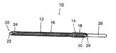
- FIG. 1is a perspective view of a distraction pin according to the invention
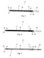
- FIG. 2is a side elevation view of the distraction pin according to the invention.
- FIG. 3is a longitudinal section view of the distraction pin according to the invention.
- FIG. 4is an exploded perspective view of the pin, with shaft removed, and the driver device of the invention
- FIG. 5is an enlarged broken perspective view of a second portion of the pin and a socket of the driver.
- FIG. 6is an enlarged broken perspective view a mill tool according to the invention.
- an internal fixation devicecomprises a preferably stainless steel pin 10 having a first and second longitudinal portions 12 , 14 .
- the first portion 12has a first diameter and threads 16 of a first thread diameter
- the second portion 14has a relatively larger second diameter and threads 18 of a relatively larger second thread diameter.
- Threads 16 and 18extend in the same rotational direction, are substantially uninterrupted along the length of the pin, and preferably are continuous with each other. That is, threads 16 preferably become threads 18 at the change in diameter from first portion 12 to second portion 14 .
- the first portionhas a length of approximately 2.55 inches and a diameter of approximately 0.125 inch
- the second portionhas length of approximately 0.6 inch and a diameter of approximately 0.015 inch, although pins having other relative dimensions may be used.
- the threads 16 , 18 on each of the first and second portions 12 , 14have the same pitch and thread depth.
- a currently preferred thread pitchis forty threads per inch, and a preferred thread depth is 0.016 inch.
- the first portion 12includes a self-tapping tip 20 adapted to provide increased purchase in the radial shaft cortex.
- the tip 20is preferably conical and defined by a surface 22 at a 30° angle relative to the longitudinal axis A of the pin (FIG. 3 ).
- the tip 12preferably includes three cutting flutes 24 . As such, the tip is a drill as well as self-tapping.
- the pin 10does not include a conventional enlarged head portion opposite the tip 20 . Rather, the pin 10 is provided with a preferably non-threaded shaft portion 26 which is preferably smaller in diameter than the second portion 14 .
- the shaft portion 26is a means by which to rotate the pin 10 for threaded insertion into bone.
- the shaft portionis adapted to be received in a chuck of a drill device.
- the shaft portion 26may be circular, hexagonal or any other shape in cross-section, provided it may be gripped by a rotational driving tool.
- the shaft portionpreferably has a length of approximately 0.8 inch and a diameter of 0.09-0.10 inch.
- the shaft portion 26is intended to be decoupled from the second portion 14 .
- a circumferential channel 28is preferably provided at the intersection of the second portion and the shaft portion.
- the channelis preferably approximately 0.02 to 0.03 inch wide and preferably approximately 0.025 inch deep.
- the second portion 14is provided with a plurality of circumferentially spaced-apart longitudinal grooves 30 adjacent its intersection with the shaft portion 26 .
- the groovesare channels, furrows, flutes, or other preferably longitudinal negative spaces defined about the circumference of the second portion.
- three grooves 30are provided and preferably spaced apart 120° about the circumference of the second portion 14 and preferably have a depth which extends below the threads 18 .
- the fracturePrior to use, if necessary, the fracture is first reduced. Then, the shaft portion 26 of the pin 10 , engaged in a chuck of a drill or other rotational driving device, is percutaneously introduced to the bone and rotationally drilled through the distal fragment, across the fracture, and into the radial shaft cortex.
- the self-tapping tip 20facilitates initial insertion into the bone and as well as purchase of the tip in the radial shaft cortex.
- the threads 16 on the first portion 12with their particular depth and pitch, provide a stable engagement with the shaft of the radial shaft bone proximal of the fracture. As the pin is inserted further, the second portion 16 enters the distal fragment and the wider threads 18 provide superior purchase on the distal fragment of bone.
- the pin 10is inserted until the intersection of the second portion 16 and the shaft portion 26 lies flush with, or more preferably slightly recessed relative to, the surface of the distal fragment.
- the shaft of the pinis then removed from the pin, e.g., by bending or cutting. It is noted that the headless design does not cause the distal fragment to be compressed against the radial shaft from which it separated.
- the first and second portions 12 , 14with threads of the same pitch and thread depth, the reduction of the fracture provided by the physician is not disturbed or acted against by the screw, but rather maintained.
- the pin of the inventioncan be used to maintain a reduced fracture in a distracted state.
- the plurality of grooves 30are accessible at the end of the second portion.
- the grooves 30provide a means for engaging the pin 10 such that, should pin removal be necessary after insertion, the headless pin can be retrieved.
- a driver 40including a handle 42 and a shaft 44 provided with a socket 46 is provided.
- the handle 42is preferably provided with finger engagement structure, e.g., circumferential ridges 48 and corresponding grooves 50 , for gripping by the hand of a physician, as well as a rounded back 52 adapted to seat in the palm of a physician's hand.
- the socket 46is adapted to be positioned over the end of the second portion 14 and provide rotational interference with the second portion.
- the socket 46may include internal ribs 54 adapted to rotationally interfere with the second portion 14 at the grooves 30 .
- positioning the socket 46 over the end of the second portion of the pin and rotating the driver 40 in a first directioncauses extraction of the pin from the bone, while rotating the driver in an opposite second direction causes the pin 10 to be further seated (or reseated) in the bone.
- the mill tool 60includes a shaft 62 provided with a head 64 having a plurality of serrations 66 or other bone removing structure about its periphery.
- the serrations 66are adapted to remove bone when the mill tool is rotated about the longitudinal axis of the shaft 62 .
- the head 64 of the mill toolpreferably has an outer diameter which is substantially equivalent to the outer diameter of the socket 46 .
- the mill tool 60may be provided in a handle similar to handle 42 .
- the shaft 44 of the socket 46may be removable from the handle 42 so that the shaft 62 of the mill tool 60 may be received therein.
- a handle(not shown) which includes the mill tool 60 extending in one direction, and the socket 46 extending in another direction, e.g., an opposite direction or at an angle relative thereto, may be used.
- the shaft portioncan be threadably coupled to the second portion in a manner in which the shaft portion and second portion are coupled when the shaft portion is rotated in the first rotational direction and threadably uncoupled when the shaft portion is rotated in the second rotational direction.
- the shaft portionmay be interference fit in a socket at the end of the second portion.
- the shaft portionmay have a hex wrench end and the second portion may have a hex socket end into which the hex wrench end is received.
Landscapes
- Health & Medical Sciences (AREA)
- Orthopedic Medicine & Surgery (AREA)
- Surgery (AREA)
- Life Sciences & Earth Sciences (AREA)
- Molecular Biology (AREA)
- Public Health (AREA)
- Engineering & Computer Science (AREA)
- Biomedical Technology (AREA)
- Heart & Thoracic Surgery (AREA)
- Medical Informatics (AREA)
- Veterinary Medicine (AREA)
- Animal Behavior & Ethology (AREA)
- General Health & Medical Sciences (AREA)
- Nuclear Medicine, Radiotherapy & Molecular Imaging (AREA)
- Neurology (AREA)
- Dentistry (AREA)
- Oral & Maxillofacial Surgery (AREA)
- Surgical Instruments (AREA)
- Joining Of Building Structures In Genera (AREA)
- Structures Of Non-Positive Displacement Pumps (AREA)
- Electrical Discharge Machining, Electrochemical Machining, And Combined Machining (AREA)
- Control Of El Displays (AREA)
Abstract
Description
1. Field of the Invention
This invention relates broadly to orthopedic fixation devices. More particularly, this invention relates to threaded pins for treatment of fractures, particularly of the distal radius bone.
2. State of the Art
Treatment of bone fractures, and particularly distal radius fractures, depends on the type of fracture. In a distal radius, Type I fractures include an undisplaced non-articular fracture of the distal radius that defines a distal radius fragment. Type I fractures do not require reduction or are stable post-reduction. Type II fractures include a medial/lateral or volar/dorsal non-articular displaced fracture which also defines a distal radius fragment. Type II fractures are reducible closed, but remain unstable.
Type I fractures are typically treated with casting. Casting provides immobilization and the traditional immobilization period is six to eight weeks, followed by a course of physiotherapy to restore range of motion. The length of the immobilization and the resulting loss of range of motion is undesirable to many patients, including athletes, artists, musicians, and patients with an economic urgency to return to work.
Current treatment of Type II fractures includes inserting a threaded pin across the fracture. However, pin implantation is not always entirely successful. One drawback with many threaded pins in treating distal radius fractures is that their blunt tips will not always engage the radius shaft cortex and will slide into the intramedullary canal, thereby limiting the amount of proximal purchase of the pin. This is a particular concern with fractures of older osteoporotic bone. In these patients, better purchase would allow more aggressive physiotherapy. In addition, the threaded fixation pins adapted for treatment of distal radius fractures are available in a single length and thus need to be cut after insertion. The cut ends of the pins interfere with early range of motion and, to a limited extent, irritate the subcutaneous tissue and may interfere with extensor tendon function. Moreover, as the pins protrude above the bone surface, a second operation is require to remove the pins.
It is therefore an object of the invention to provide a fixation device for the treatment of Type I fractures that require early mobilization and Type II fractures that are reducible closed but unstable.
It is another object of the invention to provide a fixation device that permits immediate post-operative range of motion.
It is a further object of the invention to provide a fixation device that is adapted for increased purchase in the bone.
It is an additional object of the invention to provide a fixation device that will not irritate subcutaneous tissue or interfere with extensor tendon function.
It is also an object of the invention to provide a fixation device that does not require removal after insertion.
It is still another object of the invention to provide a fixation device that is relatively easy to insert into bone.
It is yet another object of the invention to provide a fixation device particularly adapted for treatment of distal radius fractures, and which may also be used for the treatment of other fractures, such as olecranon fractures and malleolus fractures.
In accord with these objects, which will be discussed in detail below, an internal fixation device comprises a threaded pin having first and second longitudinal portions. The first portion has a first diameter and threads of a first thread diameter, and the second portion has a relatively larger second diameter and threads of a relatively larger second thread diameter.
According to a preferred aspect of the invention, the threads on each of the first and second portions have the same pitch and thread depth. The first portion includes a self-tapping tip adapted to provide increased purchase in the radial shaft cortex. No enlarged head portion is provided to the pin at the end opposite the tip.
According to another preferred aspect of the invention, a preferably non-threaded shaft portion is frangibly connected to the second portion and is a means by which to rotate the pin for threaded insertion into bone. In particularly, the shaft portion is adapted to be received in a chuck of a drill device such that the pin may be rotated by the drill device. In order to facilitate decoupling of the shaft portion from the second portion (i.e., after pin insertion), a circumferential channel is preferably provided at the intersection of the second portion and the shaft portion.
According to yet another preferred aspect of the invention, the second portion is provided with a plurality of, and preferably three, circumferentially spaced-apart longitudinal grooves adjacent its intersection with the shaft portion.
In use, the pin is held by the shaft portion and rotatably inserted into bone across the fracture. The self-tapping tip facilitates initial insertion into the bone as well as purchase of the tip of the pin in the radial shaft cortex. The threads on the first portion provide a stable engagement with the shaft of the bone proximal of the fracture. The wider threads at the second portion provide superior purchase on the distal fragment of bone located distal of the fracture. In addition, the headless design does not cause the distal fragment to be compressed against the radial shaft from which it separated. Further, by providing the first and second portions with threads of the same pitch and thread depth, the reduction of the fracture provided by the physician is not disturbed or acted against by the screw, but rather maintained. The pin is inserted until the second portion is flush with or slightly recessed into the distal fragment. The shaft of the pin is then removed from the pin, e.g., by bending or cutting.
The plurality of grooves at the second portion provide a means for rotating the pin after the shaft is removed, as described below. Thus, should pin removal be necessary after insertion, the headless pin can be retrieved. To that end, a driver device including a handle and a shaft provided with a socket is provided. The socket is adapted to be positioned over the end of the second portion of the pin (after the shaft has been removed) and to rotationally interfere with the grooved end of the second portion of the pin. As such, rotation of the driver permits removal of the pin from bone after the pin has been threadably inserted flush with or recessed into the distal fragment bone.
The pin may be used to treat olecranon fractures, malleolus fractures, and fractures of similar bones, and provides the same above described advantages when used therefor.
Additional objects and advantages of the invention will become apparent to those skilled in the art upon reference to the detailed description taken in conjunction with the provided figures.
Turning now toFIGS. 1 through 3 , an internal fixation device comprises a preferablystainless steel pin 10 having a first and secondlongitudinal portions first portion 12 has a first diameter andthreads 16 of a first thread diameter, and thesecond portion 14 has a relatively larger second diameter andthreads 18 of a relatively larger second thread diameter.Threads threads 16 preferably becomethreads 18 at the change in diameter fromfirst portion 12 tosecond portion 14. Preferably there is no length ofpin 10 between the first andsecond portions tip 20. In a preferred embodiment suitable for fixation of Type I and Type II distal radius fractures, the first portion has a length of approximately 2.55 inches and a diameter of approximately 0.125 inch, and the second portion has length of approximately 0.6 inch and a diameter of approximately 0.015 inch, although pins having other relative dimensions may be used.
According to a preferred aspect of the invention, thethreads second portions first portion 12 includes a self-tappingtip 20 adapted to provide increased purchase in the radial shaft cortex. Thetip 20 is preferably conical and defined by asurface 22 at a 30° angle relative to the longitudinal axis A of the pin (FIG.3). In addition, thetip 12 preferably includes three cuttingflutes 24. As such, the tip is a drill as well as self-tapping.
Thepin 10 does not include a conventional enlarged head portion opposite thetip 20. Rather, thepin 10 is provided with a preferablynon-threaded shaft portion 26 which is preferably smaller in diameter than thesecond portion 14. Theshaft portion 26 is a means by which to rotate thepin 10 for threaded insertion into bone. In particular, the shaft portion is adapted to be received in a chuck of a drill device. As such, theshaft portion 26 may be circular, hexagonal or any other shape in cross-section, provided it may be gripped by a rotational driving tool. The shaft portion preferably has a length of approximately 0.8 inch and a diameter of 0.09-0.10 inch.
According to another preferred aspect of the invention, theshaft portion 26 is intended to be decoupled from thesecond portion 14. In order to facilitate decoupling of theshaft portion 26 from thesecond portion 14, acircumferential channel 28 is preferably provided at the intersection of the second portion and the shaft portion. The channel is preferably approximately 0.02 to 0.03 inch wide and preferably approximately 0.025 inch deep. Then, when theshaft portion 26 is desired to be separated from thepin 10, the shaft portion may be frangibly detached from the second portion, e.g., by bending. If theshaft portion 26 cannot be frangibly separated, thechannel 28 provides a guide and a purchase for a cutting instrument to act on thepin 10 to separate theshaft portion 26 from the pin. It is recognized that even if a channel is not provided to the pin, the shaft portion may nevertheless be removed by cutting.
According to yet another preferred aspect of the invention, thesecond portion 14 is provided with a plurality of circumferentially spaced-apartlongitudinal grooves 30 adjacent its intersection with theshaft portion 26. The grooves are channels, furrows, flutes, or other preferably longitudinal negative spaces defined about the circumference of the second portion. Most preferably, threegrooves 30 are provided and preferably spaced apart 120° about the circumference of thesecond portion 14 and preferably have a depth which extends below thethreads 18.
Prior to use, if necessary, the fracture is first reduced. Then, theshaft portion 26 of thepin 10, engaged in a chuck of a drill or other rotational driving device, is percutaneously introduced to the bone and rotationally drilled through the distal fragment, across the fracture, and into the radial shaft cortex. The self-tappingtip 20 facilitates initial insertion into the bone and as well as purchase of the tip in the radial shaft cortex. Thethreads 16 on thefirst portion 12, with their particular depth and pitch, provide a stable engagement with the shaft of the radial shaft bone proximal of the fracture. As the pin is inserted further, thesecond portion 16 enters the distal fragment and thewider threads 18 provide superior purchase on the distal fragment of bone. Thepin 10 is inserted until the intersection of thesecond portion 16 and theshaft portion 26 lies flush with, or more preferably slightly recessed relative to, the surface of the distal fragment. The shaft of the pin is then removed from the pin, e.g., by bending or cutting. It is noted that the headless design does not cause the distal fragment to be compressed against the radial shaft from which it separated. In addition, by providing the first andsecond portions
Referring toFIGS. 4 and 5 , after the shaft portion has been removed from the pin, the plurality ofgrooves 30 are accessible at the end of the second portion. Thegrooves 30 provide a means for engaging thepin 10 such that, should pin removal be necessary after insertion, the headless pin can be retrieved. To that end, adriver 40 including ahandle 42 and ashaft 44 provided with asocket 46 is provided. Thehandle 42 is preferably provided with finger engagement structure, e.g.,circumferential ridges 48 andcorresponding grooves 50, for gripping by the hand of a physician, as well as a rounded back52 adapted to seat in the palm of a physician's hand. Thesocket 46 is adapted to be positioned over the end of thesecond portion 14 and provide rotational interference with the second portion. For example, thesocket 46 may includeinternal ribs 54 adapted to rotationally interfere with thesecond portion 14 at thegrooves 30. As such, positioning thesocket 46 over the end of the second portion of the pin and rotating thedriver 40 in a first direction causes extraction of the pin from the bone, while rotating the driver in an opposite second direction causes thepin 10 to be further seated (or reseated) in the bone.
Turning now toFIG. 6 , it is recognized that thesocket 46 has a larger diameter than the end of thesecond portion 14 of thepin 10. Therefore, if it is desirable to remove a recessed pin, it may be necessary to remove a small amount of bone to provide access for the socket to fit over the pin. To that end, it is preferable that amill tool 60 be provided. Themill tool 60 includes ashaft 62 provided with ahead 64 having a plurality ofserrations 66 or other bone removing structure about its periphery. Theserrations 66 are adapted to remove bone when the mill tool is rotated about the longitudinal axis of theshaft 62. Thehead 64 of the mill tool preferably has an outer diameter which is substantially equivalent to the outer diameter of thesocket 46. Themill tool 60 may be provided in a handle similar to handle42. For example, theshaft 44 of thesocket 46 may be removable from thehandle 42 so that theshaft 62 of themill tool 60 may be received therein. Alternatively, a handle (not shown) which includes themill tool 60 extending in one direction, and thesocket 46 extending in another direction, e.g., an opposite direction or at an angle relative thereto, may be used.
There have been described and illustrated herein an embodiment of a fracture fixation pin. While a particular embodiment of the invention has been described, it is not intended that the invention be limited thereto, as it is intended that the invention be as broad in scope as the art will allow and that the specification be read likewise. Thus, it will be appreciated that pins of other dimensions, having one or more of the preferred aspects of the invention are in accord with the scope of the invention. In addition, while particular thread pitches and depths have been disclosed, it will be understood that the threads of the pin can have other pitches and depth. Also, while the shaft portion is preferably frangibly connected to the threaded portion, it will be recognized that the shaft portion may be otherwise coupled thereto. For example, the shaft portion can be threadably coupled to the second portion in a manner in which the shaft portion and second portion are coupled when the shaft portion is rotated in the first rotational direction and threadably uncoupled when the shaft portion is rotated in the second rotational direction. Alternatively, the shaft portion may be interference fit in a socket at the end of the second portion. For example, the shaft portion may have a hex wrench end and the second portion may have a hex socket end into which the hex wrench end is received. It will therefore be appreciated by those skilled in the art that yet other modifications could be made to the provided invention without deviating from its spirit and scope as claimed.
Claims (21)
1. A fracture fixation pin, comprising:
a) a solid first portion having a first diameter and first threads of a first thread diameter, said first portion having a tip at one end and a second end;
b) a solid second portion coupled to said second end of said first portion, said second portion having a second diameter larger than said first diameter, and second threads of a second thread diameter larger than said first thread diameter, said second threads extending in a same direction as said first threads; and
c) a solid non-threaded shaft portion coupled to said second portion, said shall portion having a cross-sectional dimension which does not exceed a dimension of said second diameter,
wherein said second portion is provided with a plurality of longitudinal grooves extending crosswise through at least one of said second threads, said grooves being located adjacent said shaft portion and spaced-apart about an outer circumference of said second portion.
2. A fracture fixation pin according toclaim 1 , wherein:
said first and second threads are continuous.
3. A fracture fixation pin according toclaim 1 , wherein:
said tip includes a plurality of cutting flutes.
4. A fracture fixation pin according toclaim 1 , wherein:
said tip is substantially conical and includes a surface angled at 30° relative to a longitudinal axis.
5. A fracture fixation pin according toclaim 1 , wherein:
said first portion has a first length of approximately 2.55 inches and a first diameter of approximately 0.125 inch, and said second portion has a second length of approximately 0.6 inch and a second diameter of approximately 0.156 inch.
6. A fracture fixation pin according toclaim 1 , wherein:
said shaft portion is substantially cylindrical.
7. A fracture fixation pin according toclaim 1 , wherein:
said shaft is frangibly coupled to second portion.
8. A fracture fixation pin according toclaim 1 , wherein:
a channel is provided about said pin between said second portion and said shaft portion.
9. A fracture fixation pin according toclaim 1 , wherein:
said shaft has cross-sectional dimension smaller than said second diameter of said second portion.
10. A fracture fixation pin according toclaim 1 , wherein:
said pin is not provided with a head portion.
11. A fracture fixation pin according toclaim 1 , wherein:
all threads on said first portion have said first thread diameter.
12. A fracture fixation pin according toclaim 1 , wherein:
said pin is made of metal.
13. A fracture fixation pin according toclaim 1 , wherein:
said plurality of grooves includes exactly three grooves spaced apart 120° about said circumference of said second portion.
14. A fracture fixation pin according toclaim 1 , wherein:
each of said grooves has a depth which extends below said second threads.
15. A fracture fixation pin system, comprising:
a) a pin including
i) a first portion having a first diameter and first threads of a first thread diameter, said first portion having a tip at one end and a second end,
ii) a second portion coupled to said second end of said first portion, said second portion having a second diameter larger than said first diameter, and second threads along substantially an entirety thereof, said second threads of a second thread diameter larger than said first thread diameter, said first and second threads being continuous with each other and having a common pitch and thread depth, and
iii) a non-threaded shaft portion coupled to said second portion, said shaft portion having a cross-sectional dimension which does not exceed a dimension of said second diameter,
said second portion adjacent said shaft portion defining a plurality of longitudinal spaced apart negative spaces about an outer circumference thereof; and
b) a driver member including a socket having structure adapted to interfere with said negative spaces.
16. A fracture fixation pin system according toclaim 15 , further comprising:
c) a mill tool having structure adapted to remove bone and define an opening in the bone into which said socket of said driver member can be inserted.
17. A fracture fixation pin, comprising:
a) a first portion having a first diameter and first threads of a first thread diameter, said first portion having a tip at one end and a second end; and
b) a second portion having a first end coupled to said second end of said first portion and a second free end, said second portion having a second diameter larger than said first diameter, and second threads of a second thread diameter larger than said first thread diameter, said first and second threads being continuous with each other and having a common pitch and thread depth, wherein said second free end is provided with a plurality longitudinal grooves spaced-apart about an outermost circumference of said second portion and extending crosswise through at least one of said second threads.
18. A fracture fixation pin according toclaim 17 , wherein:
said plurality of grooves includes three grooves spaced apart 120° about said circumference of the second portion.
19. A fracture fixation pin according toclaim 17 , wherein:
each of said grooves has a depth which extends below said second threads.
20. A fracture fixation pin system, comprising:
a) a one-piece pin including
i) a non-hollow first portion having a first diameter and first threads of a first thread diameter, said first portion having a tip at one end and a second end, and
ii) a non-hollow second portion having a first end coupled to said second end of said first portion and a second free end, said second portion having a second diameter larger than said first diameter, and second threads of a second thread diameter larger than said first thread diameter, said first and second threads being continuous with each other and having a common pitch and thread depth, wherein said second free end is provided with a plurality of longitudinal grooves spaced-apart about an outer circumference of said second portion; and
b) a driver member including a socket having structure adapted to interfere with said grooves on said second portion of said pin.
21. A fracture fixation pin system according toclaim 20 , further comprising:
c) a mill tool having structure adapted to remove bone and define an opening in the bone into which said socket of said driver member can be inserted.
Priority Applications (10)
| Application Number | Priority Date | Filing Date | Title |
|---|---|---|---|
| US10/076,678US6875215B2 (en) | 2002-02-15 | 2002-02-15 | Distraction pin for fracture fixation |
| AU2003217729AAU2003217729A1 (en) | 2002-02-15 | 2003-01-28 | Distraction pin for fracture fixation |
| PCT/US2003/005783WO2003070118A1 (en) | 2002-02-15 | 2003-01-28 | Distraction pin for fracture fixation |
| AT03707845TATE467393T1 (en) | 2002-02-15 | 2003-02-12 | DISTRACTION PIN FOR FIXATION OF FRACTURES |
| AU2003209115AAU2003209115A1 (en) | 2002-02-15 | 2003-02-12 | Distraction pin for fracture fixation |
| EP03707845AEP1482844B1 (en) | 2002-02-15 | 2003-02-12 | Distraction pin for fracture fixation |
| DE60332524TDE60332524D1 (en) | 2002-02-15 | 2003-02-12 | DISTRAKTIONSSTIFT FÜR FIXIERUNG FRRAKTUREN |
| CA2476388ACA2476388C (en) | 2002-02-15 | 2003-02-12 | Distraction pin for fracture fixation |
| PCT/US2003/004100WO2003070117A1 (en) | 2002-02-15 | 2003-02-12 | Distraction pin for fracture fixation |
| US11/085,315US20050165402A1 (en) | 2002-02-15 | 2005-03-21 | Cannulated distraction pin for fracture fixation |
Applications Claiming Priority (1)
| Application Number | Priority Date | Filing Date | Title |
|---|---|---|---|
| US10/076,678US6875215B2 (en) | 2002-02-15 | 2002-02-15 | Distraction pin for fracture fixation |
Related Child Applications (1)
| Application Number | Title | Priority Date | Filing Date |
|---|---|---|---|
| US11/085,315Continuation-In-PartUS20050165402A1 (en) | 2002-02-15 | 2005-03-21 | Cannulated distraction pin for fracture fixation |
Publications (2)
| Publication Number | Publication Date |
|---|---|
| US20030158556A1 US20030158556A1 (en) | 2003-08-21 |
| US6875215B2true US6875215B2 (en) | 2005-04-05 |
Family
ID=27732528
Family Applications (2)
| Application Number | Title | Priority Date | Filing Date |
|---|---|---|---|
| US10/076,678Expired - LifetimeUS6875215B2 (en) | 2002-02-15 | 2002-02-15 | Distraction pin for fracture fixation |
| US11/085,315AbandonedUS20050165402A1 (en) | 2002-02-15 | 2005-03-21 | Cannulated distraction pin for fracture fixation |
Family Applications After (1)
| Application Number | Title | Priority Date | Filing Date |
|---|---|---|---|
| US11/085,315AbandonedUS20050165402A1 (en) | 2002-02-15 | 2005-03-21 | Cannulated distraction pin for fracture fixation |
Country Status (7)
| Country | Link |
|---|---|
| US (2) | US6875215B2 (en) |
| EP (1) | EP1482844B1 (en) |
| AT (1) | ATE467393T1 (en) |
| AU (2) | AU2003217729A1 (en) |
| CA (1) | CA2476388C (en) |
| DE (1) | DE60332524D1 (en) |
| WO (2) | WO2003070118A1 (en) |
Cited By (78)
| Publication number | Priority date | Publication date | Assignee | Title |
|---|---|---|---|---|
| US20030204189A1 (en)* | 2000-02-16 | 2003-10-30 | Cragg Andrew H. | Axial spinal implant and method and apparatus for implanting an axial spinal implant within the vertebrae of the spine |
| US20040181222A1 (en)* | 2003-01-16 | 2004-09-16 | Culbert Brad S. | Locking plate for bone anchors |
| US20040220577A1 (en)* | 2000-02-16 | 2004-11-04 | Cragg Andrew H. | Methods and apparatus for forming shaped axial bores through spinal vertebrae |
| US20050131411A1 (en)* | 2001-03-30 | 2005-06-16 | Culbert Brad S. | Method and apparatus for bone fixation with secondary compression |
| US20050261695A1 (en)* | 2000-02-16 | 2005-11-24 | Cragg Andrew H | Method and apparatus for spinal distraction and fusion |
| US20060039772A1 (en)* | 2003-02-12 | 2006-02-23 | Romano Matthys-Mark | Screw with integrated screwdriver |
| US20060089647A1 (en)* | 2004-08-20 | 2006-04-27 | Culbert Brad S | Method and apparatus for delivering an agent |
| US20060116686A1 (en)* | 2004-11-30 | 2006-06-01 | Stryker Trauma Sa | Self-guiding threaded fastener |
| US20070055260A1 (en)* | 2003-06-10 | 2007-03-08 | Cragg Andrew H | Method and apparatus for providing posterior or anterior trans-sacral access to spinal vertebrae |
| US20070106283A1 (en)* | 2005-11-07 | 2007-05-10 | Garcia Saddy R | Driver assembly and fastener apparatus |
| US20070233260A1 (en)* | 2000-02-16 | 2007-10-04 | Trans1 Inc. | Articulating spinal implant |
| US20080091199A1 (en)* | 2000-02-16 | 2008-04-17 | Trans1 Inc. | Methods and apparatus for performing therapeutic procedures in the spine |
| US20090024174A1 (en)* | 2007-07-17 | 2009-01-22 | Stark John G | Bone screws and particular applications to sacroiliac joint fusion |
| US7547317B2 (en) | 2000-02-16 | 2009-06-16 | Trans1 Inc. | Methods of performing procedures in the spine |
| US20090216238A1 (en)* | 2008-02-27 | 2009-08-27 | Stark John G | Tools for performing less invasive orthopedic joint procedures |
| US20100131011A1 (en)* | 2003-03-10 | 2010-05-27 | Ilion Medical, Inc. | Sacroiliac joint immobilization |
| US20100291506A1 (en)* | 2008-01-25 | 2010-11-18 | Lennart Olsson | Device for debridement of implants, and a method for debridement of implants using the device |
| US20110009865A1 (en)* | 2009-07-13 | 2011-01-13 | Orfaly Robert M | Bone fixation using an intramedullary pin |
| US20110022173A1 (en)* | 2009-07-24 | 2011-01-27 | Warsaw Orthopedic, Inc. | Implant with an interference fit fastener |
| US20110060369A1 (en)* | 2003-10-23 | 2011-03-10 | Trans1 Inc. | Method and apparatus for manipulating material in the spine |
| US20110120972A1 (en)* | 2009-11-20 | 2011-05-26 | Meyer Tool, Inc. | Replacement process for fluoride ion cleaning |
| US20110184471A1 (en)* | 2010-01-28 | 2011-07-28 | Warsaw Orthopedic, Inc. | Bone anchor with predetermined break point and removal features |
| US20130131678A1 (en)* | 2010-06-03 | 2013-05-23 | The University Of North Carolina At Chapel Hill | Threaded elastic intramedullary nails devices and methods |
| US8906075B2 (en) | 2010-07-14 | 2014-12-09 | DePuy Synthes Products, LLC | Methods and assemblies for aligning a bone fixation plate |
| US9522070B2 (en) | 2013-03-07 | 2016-12-20 | Interventional Spine, Inc. | Intervertebral implant |
| USD774686S1 (en)* | 2015-02-27 | 2016-12-20 | Star Headlight & Lantern Co., Inc. | Optical lens for projecting light from LED light emitters |
| USD775407S1 (en)* | 2015-02-27 | 2016-12-27 | Star Headlight & Lantern Co., Inc. | Optical lens for projecting light from LED light emitters |
| US9743959B2 (en) | 2013-03-14 | 2017-08-29 | Atlas Spine, Inc. | Low profile spinal fixation system |
| US9814598B2 (en) | 2013-03-14 | 2017-11-14 | Quandary Medical, Llc | Spinal implants and implantation system |
| US9839530B2 (en) | 2007-06-26 | 2017-12-12 | DePuy Synthes Products, Inc. | Highly lordosed fusion cage |
| US9883951B2 (en) | 2012-08-30 | 2018-02-06 | Interventional Spine, Inc. | Artificial disc |
| US9895236B2 (en) | 2010-06-24 | 2018-02-20 | DePuy Synthes Products, Inc. | Enhanced cage insertion assembly |
| US9913727B2 (en) | 2015-07-02 | 2018-03-13 | Medos International Sarl | Expandable implant |
| US9931223B2 (en) | 2008-04-05 | 2018-04-03 | DePuy Synthes Products, Inc. | Expandable intervertebral implant |
| US9993349B2 (en) | 2002-06-27 | 2018-06-12 | DePuy Synthes Products, Inc. | Intervertebral disc |
| US10058433B2 (en) | 2012-07-26 | 2018-08-28 | DePuy Synthes Products, Inc. | Expandable implant |
| US10111695B2 (en) | 2001-03-30 | 2018-10-30 | DePuy Synthes Products, Inc. | Distal bone anchors for bone fixation with secondary compression |
| US10136929B2 (en) | 2015-07-13 | 2018-11-27 | IntraFuse, LLC | Flexible bone implant |
| US10154863B2 (en) | 2015-07-13 | 2018-12-18 | IntraFuse, LLC | Flexible bone screw |
| US10231768B2 (en) | 2003-05-30 | 2019-03-19 | DePuy Synthes Products, Inc. | Methods for implanting bone plates |
| US10335211B2 (en) | 2004-01-26 | 2019-07-02 | DePuy Synthes Products, Inc. | Highly-versatile variable-angle bone plate system |
| US10342586B2 (en) | 2003-08-26 | 2019-07-09 | DePuy Synthes Products, Inc. | Bone plate |
| US10390963B2 (en) | 2006-12-07 | 2019-08-27 | DePuy Synthes Products, Inc. | Intervertebral implant |
| US10398563B2 (en) | 2017-05-08 | 2019-09-03 | Medos International Sarl | Expandable cage |
| US10433977B2 (en) | 2008-01-17 | 2019-10-08 | DePuy Synthes Products, Inc. | Expandable intervertebral implant and associated method of manufacturing the same |
| US10485595B2 (en) | 2015-07-13 | 2019-11-26 | IntraFuse, LLC | Flexible bone screw |
| US10500062B2 (en) | 2009-12-10 | 2019-12-10 | DePuy Synthes Products, Inc. | Bellows-like expandable interbody fusion cage |
| US10499960B2 (en) | 2015-07-13 | 2019-12-10 | IntraFuse, LLC | Method of bone fixation |
| US10537436B2 (en) | 2016-11-01 | 2020-01-21 | DePuy Synthes Products, Inc. | Curved expandable cage |
| US10548741B2 (en) | 2010-06-29 | 2020-02-04 | DePuy Synthes Products, Inc. | Distractible intervertebral implant |
| US10624686B2 (en) | 2016-09-08 | 2020-04-21 | DePuy Synthes Products, Inc. | Variable angel bone plate |
| US10772665B2 (en) | 2018-03-29 | 2020-09-15 | DePuy Synthes Products, Inc. | Locking structures for affixing bone anchors to a bone plate, and related systems and methods |
| US10820930B2 (en) | 2016-09-08 | 2020-11-03 | DePuy Synthes Products, Inc. | Variable angle bone plate |
| US10888433B2 (en) | 2016-12-14 | 2021-01-12 | DePuy Synthes Products, Inc. | Intervertebral implant inserter and related methods |
| US10905476B2 (en) | 2016-09-08 | 2021-02-02 | DePuy Synthes Products, Inc. | Variable angle bone plate |
| US10925651B2 (en) | 2018-12-21 | 2021-02-23 | DePuy Synthes Products, Inc. | Implant having locking holes with collection cavity for shavings |
| US10940016B2 (en) | 2017-07-05 | 2021-03-09 | Medos International Sarl | Expandable intervertebral fusion cage |
| US11013541B2 (en) | 2018-04-30 | 2021-05-25 | DePuy Synthes Products, Inc. | Threaded locking structures for affixing bone anchors to a bone plate, and related systems and methods |
| US11026727B2 (en) | 2018-03-20 | 2021-06-08 | DePuy Synthes Products, Inc. | Bone plate with form-fitting variable-angle locking hole |
| US11259851B2 (en) | 2003-08-26 | 2022-03-01 | DePuy Synthes Products, Inc. | Bone plate |
| US11272969B2 (en)* | 2016-10-25 | 2022-03-15 | Swemac Innovation Ab | Osseous pin, guide sleeve therefor, extraction member therefor and kit |
| US11291484B2 (en) | 2004-01-26 | 2022-04-05 | DePuy Synthes Products, Inc. | Highly-versatile variable-angle bone plate system |
| US11344424B2 (en) | 2017-06-14 | 2022-05-31 | Medos International Sarl | Expandable intervertebral implant and related methods |
| US20220175434A1 (en)* | 2016-01-12 | 2022-06-09 | ExsoMed Corporation | Bone stabilization device |
| US11426286B2 (en) | 2020-03-06 | 2022-08-30 | Eit Emerging Implant Technologies Gmbh | Expandable intervertebral implant |
| US11426290B2 (en) | 2015-03-06 | 2022-08-30 | DePuy Synthes Products, Inc. | Expandable intervertebral implant, system, kit and method |
| US11446156B2 (en) | 2018-10-25 | 2022-09-20 | Medos International Sarl | Expandable intervertebral implant, inserter instrument, and related methods |
| US11452607B2 (en) | 2010-10-11 | 2022-09-27 | DePuy Synthes Products, Inc. | Expandable interspinous process spacer implant |
| US11510788B2 (en) | 2016-06-28 | 2022-11-29 | Eit Emerging Implant Technologies Gmbh | Expandable, angularly adjustable intervertebral cages |
| US11596523B2 (en) | 2016-06-28 | 2023-03-07 | Eit Emerging Implant Technologies Gmbh | Expandable and angularly adjustable articulating intervertebral cages |
| US11612491B2 (en) | 2009-03-30 | 2023-03-28 | DePuy Synthes Products, Inc. | Zero profile spinal fusion cage |
| US11744624B2 (en)* | 2017-08-14 | 2023-09-05 | Surgebright Gmbh | Bone screw |
| US11752009B2 (en) | 2021-04-06 | 2023-09-12 | Medos International Sarl | Expandable intervertebral fusion cage |
| US11850160B2 (en) | 2021-03-26 | 2023-12-26 | Medos International Sarl | Expandable lordotic intervertebral fusion cage |
| US11911287B2 (en) | 2010-06-24 | 2024-02-27 | DePuy Synthes Products, Inc. | Lateral spondylolisthesis reduction cage |
| USRE49973E1 (en) | 2013-02-28 | 2024-05-21 | DePuy Synthes Products, Inc. | Expandable intervertebral implant, system, kit and method |
| US12090064B2 (en) | 2022-03-01 | 2024-09-17 | Medos International Sarl | Stabilization members for expandable intervertebral implants, and related systems and methods |
| US12440346B2 (en) | 2023-03-31 | 2025-10-14 | DePuy Synthes Products, Inc. | Expandable intervertebral implant |
Families Citing this family (19)
| Publication number | Priority date | Publication date | Assignee | Title |
|---|---|---|---|---|
| US6899716B2 (en)* | 2000-02-16 | 2005-05-31 | Trans1, Inc. | Method and apparatus for spinal augmentation |
| US7717958B2 (en) | 2000-02-16 | 2010-05-18 | Trans1, Inc. | Prosthetic nucleus apparatus |
| US7517350B2 (en)* | 2002-11-20 | 2009-04-14 | Orthopediatrics Corp. | Convertible threaded compression device and method of use |
| GB2406056B (en)* | 2003-09-17 | 2007-07-11 | Corin Ltd | Prosthetic cup |
| US20060058796A1 (en)* | 2004-09-14 | 2006-03-16 | Hartdegen Vernon R | Compression brace |
| US8273088B2 (en)* | 2005-07-08 | 2012-09-25 | Depuy Spine, Inc. | Bone removal tool |
| ES2346670T3 (en)* | 2005-08-15 | 2010-10-19 | Synthes Gmbh | OSTEOSYNTHESIS DEVICE. |
| WO2007086622A1 (en)* | 2006-01-27 | 2007-08-02 | Osstem Implant Co., Ltd | Fixture |
| US8382810B2 (en)* | 2007-12-05 | 2013-02-26 | Arthrex, Inc. | Torsion cutter and cannulated cutter for cutting orthopedic fasteners |
| WO2010099239A2 (en)* | 2009-02-24 | 2010-09-02 | Flex Technology, Inc. | Flexible screw |
| US20110112436A1 (en)* | 2009-11-06 | 2011-05-12 | SpineSmith Partners, LP | Distraction pins for fluid aspiration |
| ES2469872T3 (en)* | 2010-05-07 | 2014-06-20 | Klaus Pastl | Bone screw |
| US10136932B2 (en) | 2010-12-20 | 2018-11-27 | Camber Spine Technologies, LLC | Spinal plate and distraction/compression pin system |
| US20120158066A1 (en)* | 2010-12-20 | 2012-06-21 | Camber Spine Technologies, LLC | Adjustable cervical plate |
| US9474538B2 (en)* | 2012-07-18 | 2016-10-25 | Warsaw Orthopedic, Inc. | Systems and methods for guiding anchors for facet fixation |
| US10478238B2 (en) | 2014-12-02 | 2019-11-19 | Activortho, Inc. | Active compression devices, methods of assembly and methods of use |
| US11224467B2 (en) | 2016-02-26 | 2022-01-18 | Activortho, Inc. | Active compression apparatus, methods of assembly and methods of use |
| CA3015902A1 (en) | 2016-02-26 | 2017-08-31 | Activortho, Inc. | Active compression apparatus, methods of assembly and methods of use |
| US10426535B2 (en) | 2017-01-05 | 2019-10-01 | Stryker European Holdings I, Llc | Self-holding screw head |
Citations (42)
| Publication number | Priority date | Publication date | Assignee | Title |
|---|---|---|---|---|
| US2165011A (en) | 1935-02-08 | 1939-07-04 | Rosenberg Heyman | Anchorage apparatus |
| US2382019A (en) | 1944-05-02 | 1945-08-14 | Miller Edwin August | Compound screw |
| US3051169A (en)* | 1957-12-07 | 1962-08-28 | Stille Werner Ab | Surgical screw connector |
| US3463209A (en) | 1965-05-17 | 1969-08-26 | Romain Podolsky | Screw fasteners |
| US3915162A (en) | 1974-02-13 | 1975-10-28 | Peter S Miller | Orthopedic pin identification means |
| US4175555A (en) | 1977-02-24 | 1979-11-27 | Interfix Limited | Bone screw |
| US4463753A (en) | 1980-01-04 | 1984-08-07 | Gustilo Ramon B | Compression bone screw |
| US4564324A (en) | 1981-04-24 | 1986-01-14 | Hilti Aktiengesellschaft | Dowel |
| US4673323A (en) | 1986-04-07 | 1987-06-16 | Peter Russo | Self tapping stud |
| EP0276153A2 (en)* | 1987-01-22 | 1988-07-27 | Ethicon, Inc. | Bone screw |
| US4870957A (en)* | 1988-12-27 | 1989-10-03 | Marlowe Goble E | Ligament anchor system |
| WO1990002526A1 (en)* | 1988-09-09 | 1990-03-22 | Australian Defence Industries Pty. Limited | Screw |
| US5019079A (en) | 1989-11-20 | 1991-05-28 | Zimmer, Inc. | Bone screw |
| US5129901A (en)* | 1991-06-10 | 1992-07-14 | Decoste Vern X | Cannulated orthopedic screw |
| US5139400A (en) | 1989-10-11 | 1992-08-18 | Ide Russell D | Progressive cavity drive train |
| US5354299A (en) | 1992-12-07 | 1994-10-11 | Linvatec Corporation | Method of revising a screw in a tunnel |
| US5433719A (en) | 1993-03-25 | 1995-07-18 | Pennig; Dietmar | Fixation pin for small-bone fragments |
| US5499892A (en)* | 1993-06-16 | 1996-03-19 | Lock-N-Stitch International | Apparatus for repairing cracks |
| US5540531A (en) | 1993-02-24 | 1996-07-30 | Olympic Manufacturing Group, Inc. | Panel fastener |
| US5562671A (en)* | 1993-01-15 | 1996-10-08 | Depuy Inc. | Ligament replacement cross pinning method |
| US5593410A (en) | 1989-10-26 | 1997-01-14 | Vrespa; Giuseppe | Screw device for fixing prostheses to bones |
| US5609595A (en) | 1993-03-25 | 1997-03-11 | Pennig; Dietmar | Fixation pin for small-bone fragments |
| US5709687A (en) | 1994-03-16 | 1998-01-20 | Pennig; Dietmar | Fixation pin for small-bone fragments |
| US5713705A (en)* | 1996-03-01 | 1998-02-03 | Gruenbichler; Carl | Fastener bolt with limited torque head |
| US5743912A (en)* | 1995-08-23 | 1998-04-28 | Biomat | Upper femoral epiphysis osteosynthesis implant |
| US5779704A (en) | 1996-03-19 | 1998-07-14 | Kim; Andrew C. | Bi-directional universal dynamic compression device |
| US5868572A (en)* | 1995-07-05 | 1999-02-09 | Implant Innovations, Inc. | Method and means for dental bone profiling |
| US5871486A (en)* | 1993-01-21 | 1999-02-16 | Acumed, Inc. | Variable pitch bone screw |
| US5893850A (en) | 1996-11-12 | 1999-04-13 | Cachia; Victor V. | Bone fixation device |
| US5904685A (en) | 1997-04-11 | 1999-05-18 | Stryker Corporation | Screw sheath |
| US6001101A (en) | 1994-07-05 | 1999-12-14 | Depuy France | Screw device with threaded head for permitting the coaptation of two bone fragments |
| US6004349A (en)* | 1997-01-06 | 1999-12-21 | Jackson; Roger P. | Set screw for use with osteosynthesis apparatus |
| US6019762A (en) | 1998-04-30 | 2000-02-01 | Orthodyne, Inc. | Adjustable length orthopedic fixation device |
| US6030162A (en) | 1998-12-18 | 2000-02-29 | Acumed, Inc. | Axial tension screw |
| US6045554A (en) | 1996-07-16 | 2000-04-04 | University Of Florida Tissue Bank, Inc. | Cortical bone interference screw |
| US6074149A (en) | 1999-06-30 | 2000-06-13 | G. Lyle Habermehl | False threadscrew and screwstrip |
| US6086303A (en) | 1996-01-18 | 2000-07-11 | Flueckiger; Werner | Distance screw |
| US6193719B1 (en)* | 1995-08-24 | 2001-02-27 | Sofamor S.N.C. | Threaded clamping plug for interconnecting two implants of a spinal osteosynthesis instrumentation or other implants |
| US6283973B1 (en) | 1998-12-30 | 2001-09-04 | Depuy Orthopaedics, Inc. | Strength fixation device |
| US6302888B1 (en)* | 1999-03-19 | 2001-10-16 | Interpore Cross International | Locking dovetail and self-limiting set screw assembly for a spinal stabilization member |
| US6454772B1 (en)* | 2000-12-08 | 2002-09-24 | Roger P. Jackson | Set screw for medical implant with gripping side slots |
| US20030074002A1 (en)* | 2001-10-12 | 2003-04-17 | West Hugh S. | Interference screws having increased proximal diameter |
Family Cites Families (19)
| Publication number | Priority date | Publication date | Assignee | Title |
|---|---|---|---|---|
| US4059102A (en)* | 1974-08-01 | 1977-11-22 | National Research Development Corporation | Bone securing devices |
| US4414966A (en)* | 1981-04-09 | 1983-11-15 | Ace Orthopedic Manufacturing, Inc. | Fixation pin |
| US4640271A (en)* | 1985-11-07 | 1987-02-03 | Zimmer, Inc. | Bone screw |
| CH671150A5 (en)* | 1986-10-13 | 1989-08-15 | Jaquet Orthopedie | |
| DE3811345C1 (en)* | 1988-04-02 | 1989-09-07 | Aesculap Ag, 7200 Tuttlingen, De | |
| US5167664A (en)* | 1991-08-26 | 1992-12-01 | Zimmer, Inc. | Ratcheting bone screw |
| US5810817A (en)* | 1992-06-19 | 1998-09-22 | Roussouly; Pierre | Spinal therapy apparatus |
| SE510158C2 (en)* | 1992-10-29 | 1999-04-26 | Medevelop Ab | Anchorage elements for supporting prostheses and the use of such anchorage elements for fixing dentures |
| SE500383C2 (en)* | 1992-11-26 | 1994-06-13 | Medevelop Ab | Double anchored tooth fixture |
| US6299615B1 (en)* | 1993-01-21 | 2001-10-09 | Acumed, Inc. | System for fusing joints |
| DE4339804A1 (en)* | 1993-11-23 | 1995-06-01 | Haerle Anton | Power transmission link for osteosynthesis work |
| EP0872794A2 (en)* | 1997-04-16 | 1998-10-21 | Yozan Inc. | Computational circuit for adding multi-valued numbers |
| FR2788960B1 (en)* | 1999-02-02 | 2001-05-18 | Europ Foot Platform | THREADED PIN |
| US6355043B1 (en)* | 1999-03-01 | 2002-03-12 | Sulzer Orthopedics Ltd. | Bone screw for anchoring a marrow nail |
| DE59901090D1 (en)* | 1999-12-23 | 2002-05-02 | Storz Karl Gmbh & Co Kg | Decentralized drive screw |
| US6899716B2 (en)* | 2000-02-16 | 2005-05-31 | Trans1, Inc. | Method and apparatus for spinal augmentation |
| FR2808182B1 (en)* | 2000-04-28 | 2002-10-31 | Newdeal Sa | COMPRESSION SPINDLE FOR THE SOLIDARIZATION OF PHALANGES |
| AU783705B2 (en)* | 2001-07-02 | 2005-11-24 | Depuy France | Device for securing bits of bone together |
| US7278718B2 (en)* | 2002-01-22 | 2007-10-09 | Seiko Epson Corporation | Liquid injecting apparatus |
- 2002
- 2002-02-15USUS10/076,678patent/US6875215B2/ennot_activeExpired - Lifetime
- 2003
- 2003-01-28AUAU2003217729Apatent/AU2003217729A1/ennot_activeAbandoned
- 2003-01-28WOPCT/US2003/005783patent/WO2003070118A1/ennot_activeApplication Discontinuation
- 2003-02-12ATAT03707845Tpatent/ATE467393T1/ennot_activeIP Right Cessation
- 2003-02-12AUAU2003209115Apatent/AU2003209115A1/ennot_activeAbandoned
- 2003-02-12WOPCT/US2003/004100patent/WO2003070117A1/ennot_activeApplication Discontinuation
- 2003-02-12DEDE60332524Tpatent/DE60332524D1/ennot_activeExpired - Lifetime
- 2003-02-12EPEP03707845Apatent/EP1482844B1/ennot_activeExpired - Lifetime
- 2003-02-12CACA2476388Apatent/CA2476388C/ennot_activeExpired - Fee Related
- 2005
- 2005-03-21USUS11/085,315patent/US20050165402A1/ennot_activeAbandoned
Patent Citations (43)
| Publication number | Priority date | Publication date | Assignee | Title |
|---|---|---|---|---|
| US2165011A (en) | 1935-02-08 | 1939-07-04 | Rosenberg Heyman | Anchorage apparatus |
| US2382019A (en) | 1944-05-02 | 1945-08-14 | Miller Edwin August | Compound screw |
| US3051169A (en)* | 1957-12-07 | 1962-08-28 | Stille Werner Ab | Surgical screw connector |
| US3463209A (en) | 1965-05-17 | 1969-08-26 | Romain Podolsky | Screw fasteners |
| US3915162A (en) | 1974-02-13 | 1975-10-28 | Peter S Miller | Orthopedic pin identification means |
| US4175555A (en) | 1977-02-24 | 1979-11-27 | Interfix Limited | Bone screw |
| US4463753A (en) | 1980-01-04 | 1984-08-07 | Gustilo Ramon B | Compression bone screw |
| US4564324A (en) | 1981-04-24 | 1986-01-14 | Hilti Aktiengesellschaft | Dowel |
| US4673323A (en) | 1986-04-07 | 1987-06-16 | Peter Russo | Self tapping stud |
| EP0276153A2 (en)* | 1987-01-22 | 1988-07-27 | Ethicon, Inc. | Bone screw |
| WO1990002526A1 (en)* | 1988-09-09 | 1990-03-22 | Australian Defence Industries Pty. Limited | Screw |
| US4870957A (en)* | 1988-12-27 | 1989-10-03 | Marlowe Goble E | Ligament anchor system |
| US5139400A (en) | 1989-10-11 | 1992-08-18 | Ide Russell D | Progressive cavity drive train |
| US5593410A (en) | 1989-10-26 | 1997-01-14 | Vrespa; Giuseppe | Screw device for fixing prostheses to bones |
| US5019079A (en) | 1989-11-20 | 1991-05-28 | Zimmer, Inc. | Bone screw |
| US5129901A (en)* | 1991-06-10 | 1992-07-14 | Decoste Vern X | Cannulated orthopedic screw |
| US5354299A (en) | 1992-12-07 | 1994-10-11 | Linvatec Corporation | Method of revising a screw in a tunnel |
| US5645547A (en) | 1992-12-07 | 1997-07-08 | Linvatec Corporation | Revisable interference screw |
| US5562671A (en)* | 1993-01-15 | 1996-10-08 | Depuy Inc. | Ligament replacement cross pinning method |
| US5871486A (en)* | 1993-01-21 | 1999-02-16 | Acumed, Inc. | Variable pitch bone screw |
| US5540531A (en) | 1993-02-24 | 1996-07-30 | Olympic Manufacturing Group, Inc. | Panel fastener |
| US5609595A (en) | 1993-03-25 | 1997-03-11 | Pennig; Dietmar | Fixation pin for small-bone fragments |
| US5433719A (en) | 1993-03-25 | 1995-07-18 | Pennig; Dietmar | Fixation pin for small-bone fragments |
| US5499892A (en)* | 1993-06-16 | 1996-03-19 | Lock-N-Stitch International | Apparatus for repairing cracks |
| US5709687A (en) | 1994-03-16 | 1998-01-20 | Pennig; Dietmar | Fixation pin for small-bone fragments |
| US6001101A (en) | 1994-07-05 | 1999-12-14 | Depuy France | Screw device with threaded head for permitting the coaptation of two bone fragments |
| US5868572A (en)* | 1995-07-05 | 1999-02-09 | Implant Innovations, Inc. | Method and means for dental bone profiling |
| US5743912A (en)* | 1995-08-23 | 1998-04-28 | Biomat | Upper femoral epiphysis osteosynthesis implant |
| US6193719B1 (en)* | 1995-08-24 | 2001-02-27 | Sofamor S.N.C. | Threaded clamping plug for interconnecting two implants of a spinal osteosynthesis instrumentation or other implants |
| US6086303A (en) | 1996-01-18 | 2000-07-11 | Flueckiger; Werner | Distance screw |
| US5713705A (en)* | 1996-03-01 | 1998-02-03 | Gruenbichler; Carl | Fastener bolt with limited torque head |
| US5779704A (en) | 1996-03-19 | 1998-07-14 | Kim; Andrew C. | Bi-directional universal dynamic compression device |
| US6045554A (en) | 1996-07-16 | 2000-04-04 | University Of Florida Tissue Bank, Inc. | Cortical bone interference screw |
| US5893850A (en) | 1996-11-12 | 1999-04-13 | Cachia; Victor V. | Bone fixation device |
| US6004349A (en)* | 1997-01-06 | 1999-12-21 | Jackson; Roger P. | Set screw for use with osteosynthesis apparatus |
| US5904685A (en) | 1997-04-11 | 1999-05-18 | Stryker Corporation | Screw sheath |
| US6019762A (en) | 1998-04-30 | 2000-02-01 | Orthodyne, Inc. | Adjustable length orthopedic fixation device |
| US6030162A (en) | 1998-12-18 | 2000-02-29 | Acumed, Inc. | Axial tension screw |
| US6283973B1 (en) | 1998-12-30 | 2001-09-04 | Depuy Orthopaedics, Inc. | Strength fixation device |
| US6302888B1 (en)* | 1999-03-19 | 2001-10-16 | Interpore Cross International | Locking dovetail and self-limiting set screw assembly for a spinal stabilization member |
| US6074149A (en) | 1999-06-30 | 2000-06-13 | G. Lyle Habermehl | False threadscrew and screwstrip |
| US6454772B1 (en)* | 2000-12-08 | 2002-09-24 | Roger P. Jackson | Set screw for medical implant with gripping side slots |
| US20030074002A1 (en)* | 2001-10-12 | 2003-04-17 | West Hugh S. | Interference screws having increased proximal diameter |
Cited By (159)
| Publication number | Priority date | Publication date | Assignee | Title |
|---|---|---|---|---|
| US8034055B2 (en) | 1999-12-13 | 2011-10-11 | Trans1 Inc. | Method and apparatus for providing access to a presacral space |
| US20090234399A1 (en)* | 1999-12-13 | 2009-09-17 | Trans1 Inc. | Method and apparatus for providing access to a presacral space |
| US8105365B2 (en) | 2000-02-16 | 2012-01-31 | Trans1 Inc. | Methods and apparatus for performing therapeutic procedures in the spine |
| US7547317B2 (en) | 2000-02-16 | 2009-06-16 | Trans1 Inc. | Methods of performing procedures in the spine |
| US20050261695A1 (en)* | 2000-02-16 | 2005-11-24 | Cragg Andrew H | Method and apparatus for spinal distraction and fusion |
| US7794463B2 (en) | 2000-02-16 | 2010-09-14 | Trans1 Inc. | Methods and apparatus for performing therapeutic procedures in the spine |
| US8292928B2 (en) | 2000-02-16 | 2012-10-23 | Trans1 Inc. | Method and apparatus for spinal distraction and fusion |
| US7744599B2 (en) | 2000-02-16 | 2010-06-29 | Trans1 Inc. | Articulating spinal implant |
| US7727263B2 (en) | 2000-02-16 | 2010-06-01 | Trans1, Inc. | Articulating spinal implant |
| US20100004690A1 (en)* | 2000-02-16 | 2010-01-07 | Trans1 Inc. | Method and apparatus for spinal distraction and fusion |
| US20040220577A1 (en)* | 2000-02-16 | 2004-11-04 | Cragg Andrew H. | Methods and apparatus for forming shaped axial bores through spinal vertebrae |
| US8317867B2 (en) | 2000-02-16 | 2012-11-27 | Trans1 Inc. | Methods and apparatus for performing therapeutic procedures in the spine |
| US20070233260A1 (en)* | 2000-02-16 | 2007-10-04 | Trans1 Inc. | Articulating spinal implant |
| US20070233099A1 (en)* | 2000-02-16 | 2007-10-04 | Trans1 Inc. | Articulating spinal implant |
| US20090292287A1 (en)* | 2000-02-16 | 2009-11-26 | Trans1 Inc. | Methods and apparatus for tools in axially oriented bores through spinal vertebrae |
| US20080091199A1 (en)* | 2000-02-16 | 2008-04-17 | Trans1 Inc. | Methods and apparatus for performing therapeutic procedures in the spine |
| US7608077B2 (en) | 2000-02-16 | 2009-10-27 | Trans1 Inc. | Method and apparatus for spinal distraction and fusion |
| US8709087B2 (en) | 2000-02-16 | 2014-04-29 | Baxano Surgical, Inc. | Methods and apparatus for performing therapeutic procedures in the spine |
| US20030204189A1 (en)* | 2000-02-16 | 2003-10-30 | Cragg Andrew H. | Axial spinal implant and method and apparatus for implanting an axial spinal implant within the vertebrae of the spine |
| US7569056B2 (en) | 2000-02-16 | 2009-08-04 | Trans1 Inc. | Methods and apparatus for forming shaped axial bores through spinal vertebrae |
| US8715284B2 (en) | 2001-03-30 | 2014-05-06 | Interventional Spine, Inc. | Method and apparatus for bone fixation with secondary compression |
| US20050131411A1 (en)* | 2001-03-30 | 2005-06-16 | Culbert Brad S. | Method and apparatus for bone fixation with secondary compression |
| US10349991B2 (en) | 2001-03-30 | 2019-07-16 | DePuy Synthes Products, Inc. | Method and apparatus for bone fixation with secondary compression |
| US9408648B2 (en) | 2001-03-30 | 2016-08-09 | Interventional Spine, Inc. | Method and apparatus for bone fixation with secondary compression |
| US10111695B2 (en) | 2001-03-30 | 2018-10-30 | DePuy Synthes Products, Inc. | Distal bone anchors for bone fixation with secondary compression |
| US9993349B2 (en) | 2002-06-27 | 2018-06-12 | DePuy Synthes Products, Inc. | Intervertebral disc |
| US20040181222A1 (en)* | 2003-01-16 | 2004-09-16 | Culbert Brad S. | Locking plate for bone anchors |
| US20060217711A1 (en)* | 2003-01-16 | 2006-09-28 | Stevens Bruce E | Locking plate for bone anchors |
| US7070601B2 (en) | 2003-01-16 | 2006-07-04 | Triage Medical, Inc. | Locking plate for bone anchors |
| US7316532B2 (en)* | 2003-02-12 | 2008-01-08 | Synthes (U.S.A.) | Screw with integrated screwdriver |
| US20060039772A1 (en)* | 2003-02-12 | 2006-02-23 | Romano Matthys-Mark | Screw with integrated screwdriver |
| US10149764B2 (en) | 2003-03-10 | 2018-12-11 | Ilion Medical, Inc. | Sacroiliac joint immobilization |
| US9808346B2 (en) | 2003-03-10 | 2017-11-07 | Ilion Medical, Inc. | Sacroiliac joint immobilization |
| US20100131011A1 (en)* | 2003-03-10 | 2010-05-27 | Ilion Medical, Inc. | Sacroiliac joint immobilization |
| US8734456B2 (en) | 2003-03-10 | 2014-05-27 | Ilion Medical Llc | Sacroiliac joint immobilization |
| US8454618B2 (en) | 2003-03-10 | 2013-06-04 | John G. Stark | Sacroiliac joint immobilization |
| US10231768B2 (en) | 2003-05-30 | 2019-03-19 | DePuy Synthes Products, Inc. | Methods for implanting bone plates |
| US10653466B2 (en) | 2003-05-30 | 2020-05-19 | DePuy Synthes Products, Inc. | Bone plate |
| US11419647B2 (en) | 2003-05-30 | 2022-08-23 | DePuy Synthes Products, Inc. | Bone plate |
| US7641657B2 (en) | 2003-06-10 | 2010-01-05 | Trans1, Inc. | Method and apparatus for providing posterior or anterior trans-sacral access to spinal vertebrae |
| US20070055260A1 (en)* | 2003-06-10 | 2007-03-08 | Cragg Andrew H | Method and apparatus for providing posterior or anterior trans-sacral access to spinal vertebrae |
| US10342586B2 (en) | 2003-08-26 | 2019-07-09 | DePuy Synthes Products, Inc. | Bone plate |
| US11259851B2 (en) | 2003-08-26 | 2022-03-01 | DePuy Synthes Products, Inc. | Bone plate |
| US8308777B2 (en) | 2003-10-23 | 2012-11-13 | Trans1 Inc. | Method and apparatus for removable spinal implant extending between at least two adjacent vertebral bodies |
| US20110060369A1 (en)* | 2003-10-23 | 2011-03-10 | Trans1 Inc. | Method and apparatus for manipulating material in the spine |
| US11291484B2 (en) | 2004-01-26 | 2022-04-05 | DePuy Synthes Products, Inc. | Highly-versatile variable-angle bone plate system |
| US10335211B2 (en) | 2004-01-26 | 2019-07-02 | DePuy Synthes Products, Inc. | Highly-versatile variable-angle bone plate system |
| US20060089647A1 (en)* | 2004-08-20 | 2006-04-27 | Culbert Brad S | Method and apparatus for delivering an agent |
| US7799062B2 (en)* | 2004-11-30 | 2010-09-21 | Stryker Trauma S.A. | Self-guiding threaded fastener |
| US20060116686A1 (en)* | 2004-11-30 | 2006-06-01 | Stryker Trauma Sa | Self-guiding threaded fastener |
| US7846167B2 (en) | 2005-11-07 | 2010-12-07 | Biomet Microfixation, Llc | Driver assembly and fastener apparatus |
| US20070106283A1 (en)* | 2005-11-07 | 2007-05-10 | Garcia Saddy R | Driver assembly and fastener apparatus |
| US11432942B2 (en) | 2006-12-07 | 2022-09-06 | DePuy Synthes Products, Inc. | Intervertebral implant |
| US10390963B2 (en) | 2006-12-07 | 2019-08-27 | DePuy Synthes Products, Inc. | Intervertebral implant |
| US11642229B2 (en) | 2006-12-07 | 2023-05-09 | DePuy Synthes Products, Inc. | Intervertebral implant |
| US11660206B2 (en) | 2006-12-07 | 2023-05-30 | DePuy Synthes Products, Inc. | Intervertebral implant |
| US11712345B2 (en) | 2006-12-07 | 2023-08-01 | DePuy Synthes Products, Inc. | Intervertebral implant |
| US11273050B2 (en) | 2006-12-07 | 2022-03-15 | DePuy Synthes Products, Inc. | Intervertebral implant |
| US11497618B2 (en) | 2006-12-07 | 2022-11-15 | DePuy Synthes Products, Inc. | Intervertebral implant |
| US10398566B2 (en) | 2006-12-07 | 2019-09-03 | DePuy Synthes Products, Inc. | Intervertebral implant |
| US10583015B2 (en) | 2006-12-07 | 2020-03-10 | DePuy Synthes Products, Inc. | Intervertebral implant |
| US9839530B2 (en) | 2007-06-26 | 2017-12-12 | DePuy Synthes Products, Inc. | Highly lordosed fusion cage |
| US10973652B2 (en) | 2007-06-26 | 2021-04-13 | DePuy Synthes Products, Inc. | Highly lordosed fusion cage |
| US11622868B2 (en) | 2007-06-26 | 2023-04-11 | DePuy Synthes Products, Inc. | Highly lordosed fusion cage |
| US9668781B2 (en) | 2007-07-17 | 2017-06-06 | Ilion Medical, Inc. | Methods for delivery of screws for joint fusion |
| US20090024174A1 (en)* | 2007-07-17 | 2009-01-22 | Stark John G | Bone screws and particular applications to sacroiliac joint fusion |
| US11045231B2 (en) | 2007-07-17 | 2021-06-29 | Ilion Medical, Inc. | Methods for delivery of screws for joint fusion |
| WO2009011774A3 (en)* | 2007-07-17 | 2009-03-12 | Ilion Medical Llc | Bone screws and particular applications to sacroiliac joint fusion |
| US10433977B2 (en) | 2008-01-17 | 2019-10-08 | DePuy Synthes Products, Inc. | Expandable intervertebral implant and associated method of manufacturing the same |
| US11737881B2 (en) | 2008-01-17 | 2023-08-29 | DePuy Synthes Products, Inc. | Expandable intervertebral implant and associated method of manufacturing the same |
| US10449058B2 (en) | 2008-01-17 | 2019-10-22 | DePuy Synthes Products, Inc. | Expandable intervertebral implant and associated method of manufacturing the same |
| US20100291506A1 (en)* | 2008-01-25 | 2010-11-18 | Lennart Olsson | Device for debridement of implants, and a method for debridement of implants using the device |
| US20090216238A1 (en)* | 2008-02-27 | 2009-08-27 | Stark John G | Tools for performing less invasive orthopedic joint procedures |
| US8740912B2 (en) | 2008-02-27 | 2014-06-03 | Ilion Medical Llc | Tools for performing less invasive orthopedic joint procedures |
| US9314232B2 (en) | 2008-02-27 | 2016-04-19 | Ilion Medical, Inc | Tools for performing less invasive orthopedic joint procedures |
| US10682150B2 (en) | 2008-02-27 | 2020-06-16 | llion Medical, Inc. | Tools for performing less invasive orthopedic joint procedures |
| US11707359B2 (en) | 2008-04-05 | 2023-07-25 | DePuy Synthes Products, Inc. | Expandable intervertebral implant |
| US12023255B2 (en) | 2008-04-05 | 2024-07-02 | DePuy Synthes Products, Inc. | Expandable inter vertebral implant |
| US11602438B2 (en) | 2008-04-05 | 2023-03-14 | DePuy Synthes Products, Inc. | Expandable intervertebral implant |
| US9931223B2 (en) | 2008-04-05 | 2018-04-03 | DePuy Synthes Products, Inc. | Expandable intervertebral implant |
| US12011361B2 (en) | 2008-04-05 | 2024-06-18 | DePuy Synthes Products, Inc. | Expandable intervertebral implant |
| US9993350B2 (en) | 2008-04-05 | 2018-06-12 | DePuy Synthes Products, Inc. | Expandable intervertebral implant |
| US11701234B2 (en) | 2008-04-05 | 2023-07-18 | DePuy Synthes Products, Inc. | Expandable intervertebral implant |
| US11712341B2 (en) | 2008-04-05 | 2023-08-01 | DePuy Synthes Products, Inc. | Expandable intervertebral implant |
| US10449056B2 (en) | 2008-04-05 | 2019-10-22 | DePuy Synthes Products, Inc. | Expandable intervertebral implant |
| US11712342B2 (en) | 2008-04-05 | 2023-08-01 | DePuy Synthes Products, Inc. | Expandable intervertebral implant |
| US11617655B2 (en) | 2008-04-05 | 2023-04-04 | DePuy Synthes Products, Inc. | Expandable intervertebral implant |
| US11612491B2 (en) | 2009-03-30 | 2023-03-28 | DePuy Synthes Products, Inc. | Zero profile spinal fusion cage |
| US12097124B2 (en) | 2009-03-30 | 2024-09-24 | DePuy Synthes Products, Inc. | Zero profile spinal fusion cage |
| US20110009865A1 (en)* | 2009-07-13 | 2011-01-13 | Orfaly Robert M | Bone fixation using an intramedullary pin |
| US9433453B2 (en) | 2009-07-24 | 2016-09-06 | Warsaw Orthopedic, Inc. | Implant with an interference fit fastener |
| US20110022173A1 (en)* | 2009-07-24 | 2011-01-27 | Warsaw Orthopedic, Inc. | Implant with an interference fit fastener |
| US9095444B2 (en) | 2009-07-24 | 2015-08-04 | Warsaw Orthopedic, Inc. | Implant with an interference fit fastener |
| US20110120972A1 (en)* | 2009-11-20 | 2011-05-26 | Meyer Tool, Inc. | Replacement process for fluoride ion cleaning |
| US10500062B2 (en) | 2009-12-10 | 2019-12-10 | DePuy Synthes Products, Inc. | Bellows-like expandable interbody fusion cage |
| US11607321B2 (en) | 2009-12-10 | 2023-03-21 | DePuy Synthes Products, Inc. | Bellows-like expandable interbody fusion cage |
| US20110184471A1 (en)* | 2010-01-28 | 2011-07-28 | Warsaw Orthopedic, Inc. | Bone anchor with predetermined break point and removal features |
| US8523914B2 (en)* | 2010-01-28 | 2013-09-03 | Warsaw Orthopedic, Inc. | Bone anchor with predetermined break point and removal features |
| US20130131678A1 (en)* | 2010-06-03 | 2013-05-23 | The University Of North Carolina At Chapel Hill | Threaded elastic intramedullary nails devices and methods |
| US10966840B2 (en) | 2010-06-24 | 2021-04-06 | DePuy Synthes Products, Inc. | Enhanced cage insertion assembly |
| US9895236B2 (en) | 2010-06-24 | 2018-02-20 | DePuy Synthes Products, Inc. | Enhanced cage insertion assembly |
| US11872139B2 (en) | 2010-06-24 | 2024-01-16 | DePuy Synthes Products, Inc. | Enhanced cage insertion assembly |
| US11911287B2 (en) | 2010-06-24 | 2024-02-27 | DePuy Synthes Products, Inc. | Lateral spondylolisthesis reduction cage |
| US12318304B2 (en) | 2010-06-24 | 2025-06-03 | DePuy Synthes Products, Inc. | Lateral spondylolisthesis reduction cage |
| US10548741B2 (en) | 2010-06-29 | 2020-02-04 | DePuy Synthes Products, Inc. | Distractible intervertebral implant |
| US11654033B2 (en) | 2010-06-29 | 2023-05-23 | DePuy Synthes Products, Inc. | Distractible intervertebral implant |
| US8906075B2 (en) | 2010-07-14 | 2014-12-09 | DePuy Synthes Products, LLC | Methods and assemblies for aligning a bone fixation plate |
| US11452607B2 (en) | 2010-10-11 | 2022-09-27 | DePuy Synthes Products, Inc. | Expandable interspinous process spacer implant |
| US10058433B2 (en) | 2012-07-26 | 2018-08-28 | DePuy Synthes Products, Inc. | Expandable implant |
| US9883951B2 (en) | 2012-08-30 | 2018-02-06 | Interventional Spine, Inc. | Artificial disc |
| USRE49973E1 (en) | 2013-02-28 | 2024-05-21 | DePuy Synthes Products, Inc. | Expandable intervertebral implant, system, kit and method |
| US10413422B2 (en) | 2013-03-07 | 2019-09-17 | DePuy Synthes Products, Inc. | Intervertebral implant |
| US9522070B2 (en) | 2013-03-07 | 2016-12-20 | Interventional Spine, Inc. | Intervertebral implant |
| US11497619B2 (en) | 2013-03-07 | 2022-11-15 | DePuy Synthes Products, Inc. | Intervertebral implant |
| US11850164B2 (en) | 2013-03-07 | 2023-12-26 | DePuy Synthes Products, Inc. | Intervertebral implant |
| US9814598B2 (en) | 2013-03-14 | 2017-11-14 | Quandary Medical, Llc | Spinal implants and implantation system |
| US9743959B2 (en) | 2013-03-14 | 2017-08-29 | Atlas Spine, Inc. | Low profile spinal fixation system |
| US9913728B2 (en) | 2013-03-14 | 2018-03-13 | Quandary Medical, Llc | Spinal implants and implantation system |
| USD775407S1 (en)* | 2015-02-27 | 2016-12-27 | Star Headlight & Lantern Co., Inc. | Optical lens for projecting light from LED light emitters |
| USD774686S1 (en)* | 2015-02-27 | 2016-12-20 | Star Headlight & Lantern Co., Inc. | Optical lens for projecting light from LED light emitters |
| US11426290B2 (en) | 2015-03-06 | 2022-08-30 | DePuy Synthes Products, Inc. | Expandable intervertebral implant, system, kit and method |
| US9913727B2 (en) | 2015-07-02 | 2018-03-13 | Medos International Sarl | Expandable implant |
| US10492838B2 (en) | 2015-07-13 | 2019-12-03 | IntraFuse, LLC | Flexible bone implant |
| US20200078058A1 (en)* | 2015-07-13 | 2020-03-12 | IntraFuse, LLC | Flexible bone implant |
| US10136929B2 (en) | 2015-07-13 | 2018-11-27 | IntraFuse, LLC | Flexible bone implant |
| US10154863B2 (en) | 2015-07-13 | 2018-12-18 | IntraFuse, LLC | Flexible bone screw |
| US10485595B2 (en) | 2015-07-13 | 2019-11-26 | IntraFuse, LLC | Flexible bone screw |
| US10499960B2 (en) | 2015-07-13 | 2019-12-10 | IntraFuse, LLC | Method of bone fixation |
| US20220175434A1 (en)* | 2016-01-12 | 2022-06-09 | ExsoMed Corporation | Bone stabilization device |
| US12433757B2 (en) | 2016-06-28 | 2025-10-07 | Eit Emerging Implant Technologies Gmbh | Expandable, angularly adjustable and articulating intervertebral cages |
| US11510788B2 (en) | 2016-06-28 | 2022-11-29 | Eit Emerging Implant Technologies Gmbh | Expandable, angularly adjustable intervertebral cages |
| US11596522B2 (en) | 2016-06-28 | 2023-03-07 | Eit Emerging Implant Technologies Gmbh | Expandable and angularly adjustable intervertebral cages with articulating joint |
| US11596523B2 (en) | 2016-06-28 | 2023-03-07 | Eit Emerging Implant Technologies Gmbh | Expandable and angularly adjustable articulating intervertebral cages |
| US12390343B2 (en) | 2016-06-28 | 2025-08-19 | Eit Emerging Implant Technologies Gmbh | Expandable, angularly adjustable intervertebral cages |
| US11529176B2 (en) | 2016-09-08 | 2022-12-20 | DePuy Synthes Products, Inc. | Variable angle bone plate |
| US10624686B2 (en) | 2016-09-08 | 2020-04-21 | DePuy Synthes Products, Inc. | Variable angel bone plate |
| US10820930B2 (en) | 2016-09-08 | 2020-11-03 | DePuy Synthes Products, Inc. | Variable angle bone plate |
| US10905476B2 (en) | 2016-09-08 | 2021-02-02 | DePuy Synthes Products, Inc. | Variable angle bone plate |
| US11272969B2 (en)* | 2016-10-25 | 2022-03-15 | Swemac Innovation Ab | Osseous pin, guide sleeve therefor, extraction member therefor and kit |
| US10537436B2 (en) | 2016-11-01 | 2020-01-21 | DePuy Synthes Products, Inc. | Curved expandable cage |
| US10888433B2 (en) | 2016-12-14 | 2021-01-12 | DePuy Synthes Products, Inc. | Intervertebral implant inserter and related methods |
| US12427031B2 (en) | 2017-05-08 | 2025-09-30 | Medos International Sarl | Expandable cage |
| US10398563B2 (en) | 2017-05-08 | 2019-09-03 | Medos International Sarl | Expandable cage |
| US11446155B2 (en) | 2017-05-08 | 2022-09-20 | Medos International Sarl | Expandable cage |
| US11344424B2 (en) | 2017-06-14 | 2022-05-31 | Medos International Sarl | Expandable intervertebral implant and related methods |
| US10940016B2 (en) | 2017-07-05 | 2021-03-09 | Medos International Sarl | Expandable intervertebral fusion cage |
| US11744624B2 (en)* | 2017-08-14 | 2023-09-05 | Surgebright Gmbh | Bone screw |
| US11026727B2 (en) | 2018-03-20 | 2021-06-08 | DePuy Synthes Products, Inc. | Bone plate with form-fitting variable-angle locking hole |
| US10772665B2 (en) | 2018-03-29 | 2020-09-15 | DePuy Synthes Products, Inc. | Locking structures for affixing bone anchors to a bone plate, and related systems and methods |
| US11013541B2 (en) | 2018-04-30 | 2021-05-25 | DePuy Synthes Products, Inc. | Threaded locking structures for affixing bone anchors to a bone plate, and related systems and methods |
| US11446156B2 (en) | 2018-10-25 | 2022-09-20 | Medos International Sarl | Expandable intervertebral implant, inserter instrument, and related methods |
| US10925651B2 (en) | 2018-12-21 | 2021-02-23 | DePuy Synthes Products, Inc. | Implant having locking holes with collection cavity for shavings |
| US11426286B2 (en) | 2020-03-06 | 2022-08-30 | Eit Emerging Implant Technologies Gmbh | Expandable intervertebral implant |
| US11806245B2 (en) | 2020-03-06 | 2023-11-07 | Eit Emerging Implant Technologies Gmbh | Expandable intervertebral implant |
| US11850160B2 (en) | 2021-03-26 | 2023-12-26 | Medos International Sarl | Expandable lordotic intervertebral fusion cage |
| US11752009B2 (en) | 2021-04-06 | 2023-09-12 | Medos International Sarl | Expandable intervertebral fusion cage |
| US12023258B2 (en) | 2021-04-06 | 2024-07-02 | Medos International Sarl | Expandable intervertebral fusion cage |
| US12090064B2 (en) | 2022-03-01 | 2024-09-17 | Medos International Sarl | Stabilization members for expandable intervertebral implants, and related systems and methods |
| US12440346B2 (en) | 2023-03-31 | 2025-10-14 | DePuy Synthes Products, Inc. | Expandable intervertebral implant |
Also Published As
| Publication number | Publication date |
|---|---|
| EP1482844A1 (en) | 2004-12-08 |
| ATE467393T1 (en) | 2010-05-15 |
| AU2003217729A1 (en) | 2003-09-09 |
| WO2003070118A1 (en) | 2003-08-28 |
| EP1482844B1 (en) | 2010-05-12 |
| DE60332524D1 (en) | 2010-06-24 |
| AU2003209115A1 (en) | 2003-09-09 |
| US20030158556A1 (en) | 2003-08-21 |
| CA2476388A1 (en) | 2003-08-28 |
| EP1482844A4 (en) | 2006-07-26 |
| CA2476388C (en) | 2012-04-24 |
| US20050165402A1 (en) | 2005-07-28 |
| WO2003070117A1 (en) | 2003-08-28 |
Similar Documents
| Publication | Publication Date | Title |
|---|---|---|
| US6875215B2 (en) | Distraction pin for fracture fixation | |
| AU2002235407B2 (en) | Bone screw | |
| EP2501311B1 (en) | Variable angle locking buttress pins | |
| US6238417B1 (en) | Method for fixing at least two bone segments | |
| US8808338B2 (en) | Flexible bone screw | |
| US9247946B2 (en) | Method of using a drill sleeve | |
| EP2227160B1 (en) | Distal tibia plating system | |
| EP1734880B1 (en) | Adjustable tool for cannulated fasteners | |
| AU2002235407A1 (en) | Bone screw | |
| US20060264947A1 (en) | Bone fixation system | |
| JP2007083046A (en) | Bone fixation system including plate having fixed-angle hole together with unidirectional locking screw and surgeon-directed locking screw | |
| US6004321A (en) | Cannulated screw retraction apparatus and method of retraction | |
| US10660680B2 (en) | Bone treating device, bone treating screw and bone treating plate | |
| JP2019069142A (en) | Wrist stabilization systems | |
| JP2007325901A (en) | Humeral nail | |
| RU2223708C2 (en) | Rod awl for performing external perosseous osteosynthesis | |
| HK1058749B (en) | Bone screw |
Legal Events
| Date | Code | Title | Description |
|---|---|---|---|
| AS | Assignment | Owner name:TARAS, JOHN STANLEY, NEW JERSEY Free format text:ASSIGNMENT OF ASSIGNORS INTEREST;ASSIGNOR:STEFFEN, DENNIS L.;REEL/FRAME:012602/0428 Effective date:20020213 | |
| STCF | Information on status: patent grant | Free format text:PATENTED CASE | |
| FPAY | Fee payment | Year of fee payment:4 | |
| FPAY | Fee payment | Year of fee payment:8 | |
| FPAY | Fee payment | Year of fee payment:12 |