US6874522B2 - Luer-actuated solution path connector with membrane and container using the connector and a method for establishing fluid communication with the container - Google Patents
Luer-actuated solution path connector with membrane and container using the connector and a method for establishing fluid communication with the containerDownload PDFInfo
- Publication number
- US6874522B2 US6874522B2US10/173,890US17389002AUS6874522B2US 6874522 B2US6874522 B2US 6874522B2US 17389002 AUS17389002 AUS 17389002AUS 6874522 B2US6874522 B2US 6874522B2
- Authority
- US
- United States
- Prior art keywords
- coupling member
- spike
- container
- passageway
- connector
- Prior art date
- Legal status (The legal status is an assumption and is not a legal conclusion. Google has not performed a legal analysis and makes no representation as to the accuracy of the status listed.)
- Expired - Lifetime, expires
Links
- 239000012528membraneSubstances0.000titleclaimsabstractdescription58
- 239000012530fluidSubstances0.000titleclaimsabstractdescription45
- 238000004891communicationMethods0.000titleclaimsabstractdescription42
- 238000000034methodMethods0.000titleclaimsabstractdescription33
- 230000008878couplingEffects0.000claimsabstractdescription281
- 238000010168coupling processMethods0.000claimsabstractdescription281
- 238000005859coupling reactionMethods0.000claimsabstractdescription281
- 238000007789sealingMethods0.000claimsdescription2
- 239000003814drugSubstances0.000description18
- 230000008901benefitEffects0.000description11
- 229920003023plasticPolymers0.000description5
- 239000004033plasticSubstances0.000description5
- -1for exampleSubstances0.000description4
- 239000000463materialSubstances0.000description4
- 238000012790confirmationMethods0.000description3
- 238000012986modificationMethods0.000description3
- 230000004048modificationEffects0.000description3
- 230000001954sterilising effectEffects0.000description3
- 238000004659sterilization and disinfectionMethods0.000description3
- 238000010276constructionMethods0.000description2
- 238000000502dialysisMethods0.000description2
- 239000011521glassSubstances0.000description2
- 230000008569processEffects0.000description2
- 229920000298CellophanePolymers0.000description1
- 206010047531Visual acuity reducedDiseases0.000description1
- 239000000853adhesiveSubstances0.000description1
- 230000001070adhesive effectEffects0.000description1
- 230000003467diminishing effectEffects0.000description1
- 230000036512infertilityEffects0.000description1
- 210000003734kidneyAnatomy0.000description1
- 208000017169kidney diseaseDiseases0.000description1
- 239000007788liquidSubstances0.000description1
- 230000009467reductionEffects0.000description1
- 239000007787solidSubstances0.000description1
- 239000000725suspensionSubstances0.000description1
- 238000002560therapeutic procedureMethods0.000description1
Images


Classifications
- A—HUMAN NECESSITIES
- A61—MEDICAL OR VETERINARY SCIENCE; HYGIENE
- A61J—CONTAINERS SPECIALLY ADAPTED FOR MEDICAL OR PHARMACEUTICAL PURPOSES; DEVICES OR METHODS SPECIALLY ADAPTED FOR BRINGING PHARMACEUTICAL PRODUCTS INTO PARTICULAR PHYSICAL OR ADMINISTERING FORMS; DEVICES FOR ADMINISTERING FOOD OR MEDICINES ORALLY; BABY COMFORTERS; DEVICES FOR RECEIVING SPITTLE
- A61J1/00—Containers specially adapted for medical or pharmaceutical purposes
- A61J1/05—Containers specially adapted for medical or pharmaceutical purposes for collecting, storing or administering blood, plasma or medical fluids ; Infusion or perfusion containers
- A61J1/10—Bag-type containers
- A—HUMAN NECESSITIES
- A61—MEDICAL OR VETERINARY SCIENCE; HYGIENE
- A61M—DEVICES FOR INTRODUCING MEDIA INTO, OR ONTO, THE BODY; DEVICES FOR TRANSDUCING BODY MEDIA OR FOR TAKING MEDIA FROM THE BODY; DEVICES FOR PRODUCING OR ENDING SLEEP OR STUPOR
- A61M39/00—Tubes, tube connectors, tube couplings, valves, access sites or the like, specially adapted for medical use
- A61M39/10—Tube connectors; Tube couplings
- A61M39/16—Tube connectors; Tube couplings having provision for disinfection or sterilisation
- A61M39/18—Methods or apparatus for making the connection under sterile conditions, i.e. sterile docking
- A—HUMAN NECESSITIES
- A61—MEDICAL OR VETERINARY SCIENCE; HYGIENE
- A61M—DEVICES FOR INTRODUCING MEDIA INTO, OR ONTO, THE BODY; DEVICES FOR TRANSDUCING BODY MEDIA OR FOR TAKING MEDIA FROM THE BODY; DEVICES FOR PRODUCING OR ENDING SLEEP OR STUPOR
- A61M39/00—Tubes, tube connectors, tube couplings, valves, access sites or the like, specially adapted for medical use
- A61M39/10—Tube connectors; Tube couplings
- A61M2039/1027—Quick-acting type connectors
- A—HUMAN NECESSITIES
- A61—MEDICAL OR VETERINARY SCIENCE; HYGIENE
- A61M—DEVICES FOR INTRODUCING MEDIA INTO, OR ONTO, THE BODY; DEVICES FOR TRANSDUCING BODY MEDIA OR FOR TAKING MEDIA FROM THE BODY; DEVICES FOR PRODUCING OR ENDING SLEEP OR STUPOR
- A61M2205/00—General characteristics of the apparatus
- A61M2205/58—Means for facilitating use, e.g. by people with impaired vision
- A61M2205/581—Means for facilitating use, e.g. by people with impaired vision by audible feedback
- A—HUMAN NECESSITIES
- A61—MEDICAL OR VETERINARY SCIENCE; HYGIENE
- A61M—DEVICES FOR INTRODUCING MEDIA INTO, OR ONTO, THE BODY; DEVICES FOR TRANSDUCING BODY MEDIA OR FOR TAKING MEDIA FROM THE BODY; DEVICES FOR PRODUCING OR ENDING SLEEP OR STUPOR
- A61M2205/00—General characteristics of the apparatus
- A61M2205/58—Means for facilitating use, e.g. by people with impaired vision
- A61M2205/582—Means for facilitating use, e.g. by people with impaired vision by tactile feedback
- Y—GENERAL TAGGING OF NEW TECHNOLOGICAL DEVELOPMENTS; GENERAL TAGGING OF CROSS-SECTIONAL TECHNOLOGIES SPANNING OVER SEVERAL SECTIONS OF THE IPC; TECHNICAL SUBJECTS COVERED BY FORMER USPC CROSS-REFERENCE ART COLLECTIONS [XRACs] AND DIGESTS
- Y10—TECHNICAL SUBJECTS COVERED BY FORMER USPC
- Y10T—TECHNICAL SUBJECTS COVERED BY FORMER US CLASSIFICATION
- Y10T137/00—Fluid handling
- Y10T137/1624—Destructible or deformable element controlled
- Y10T137/1632—Destructible element
- Y10T137/1692—Rupture disc
- Y10T137/1759—Knife or cutter causes disc to break
- Y10T137/1767—Movable knife or cutter
Definitions
- the present inventiongenerally relates to a connector, a container using the connector and a method for establishing fluid communication with the container. More specifically, the connector relates to a first coupling member and a second coupling member between a container and a patient.
- the containermay be, for example, a flexible bag.
- the containermay contain one or more medicaments, particularly for administration from the container to the patient.
- kitssuch as in flexible bags, glass or plastic vials, or glass or plastic bottles.
- Such containersoften contain medicaments that are withdrawn from the container and administered to a patient during, for example, a kidney dialysis process.
- the containerstypically receive a coupling member and a second coupling member.
- the coupling memberis attached to or attaches to the container and directs the medicaments to the patient.
- the first coupling member and the second coupling memberattach to form a passageway for the medicaments to flow to the patient.
- the coupling memberincorporates a stopper, or alternatively, a stopper is located in the container.
- the stopperprevents the solution from exiting the container.
- the coupling memberoften includes a needle that may pierce the stopper on the container. The piercing allows fluid to flow from the container, through the coupling member and to the patient.
- a mistake-proof connectionis needed in, for example, renal therapies, to insure that the correct medicaments are administered to a patient during such treatment.
- the needle associated with known coupling memberspermit pierce any stopper which may result in the wrong medicaments being administered to a patient.
- the present inventionrelates to a connector, a container using the connector and a method for establishing fluid communication with the container. More specifically, the present invention relates to a connector and a container that retains fluid and provides an aseptic path upon engagement of the connector and a method for using the same.
- a connectorin an embodiment of the present invention, has a first coupling member having a first passageway having a diameter and a membrane in the first passageway.
- a second coupling memberis provided having a second passageway.
- a spikemay be provided in the first coupling member or the second coupling member wherein the spike has a third passageway. Connection of the first coupling member to the second coupling member penetrates the membrane of the first coupling member to provide fluid communication between the first passageway, the spike and the second passageway.
- the connectorhas a cap removably attached to the first coupling member.
- the connectorhas a cap removably attached to the second coupling member.
- the connectorhas a female connector on the first coupling member wherein the female end attaches to the second coupling member.
- the connectorhas a male connector on the second coupling member wherein the male end attaches to the first coupling member.
- the connectorhas a lip on the first coupling member wherein the lip has a diameter greater than a remainder of the first coupling member.
- the connectorhas a flange on the spike wherein the flange has a diameter greater than a remainder of the spike.
- the connectorhas a flange on the first coupling member wherein the flange has a diameter greater then a remainder of the first coupling member.
- the connectorhas a flange on the second coupling member wherein the flange has a diameter greater than a remainder of the second coupling member.
- a container having walls defining an interiorhas a tube connected to one of the walls and extending outside of the interior of the walls.
- the containerfurther has a first coupling member with a first passageway and a spike wherein the first coupling member connects to the tube and further wherein the spike is in the first passageway of the first coupling member.
- the containerfurther has a second coupling member with a second passageway wherein the second coupling member attaches to the first coupling member to provide fluid communication with the interior.
- the spikeis located within the second coupling member instead of the first coupling member.
- the containerhas a membrane in the first passageway.
- the containerhas a female connecting end associated with the first coupling member.
- the containerhas a male connecting end associated with the second coupling member.
- the containerhas a cap enclosing the spike in the first passageway of the first coupling member.
- a method for establishing fluid communication with a container having an interior wherein access to the container is provided by a porthas the steps of: attaching a first coupling member to the container wherein the coupling member has walls defining a first passageway through the coupling member between a first end and a second end; sealing the first end of the coupling member with a membrane; inserting a spike in the passageway of the coupling member between the first end and the second end; and attaching a second coupling member at the second end of the first coupling member wherein attachment of the second coupling member causes the spike to pierce the membrane.
- the methodprovides the step of covering the first end of the first coupling member to enclose the first passageway and the spike in the first passageway.
- an audible soundmay be heard upon breaking of the membrane.
- a reduction in the torque required to pierce the membranemay be felt when the membrane is ruptured.
- the methodprovides the step of securing the first coupling member to the second coupling member with a luer-lock.
- the methodprovides the step of forming a lip on the spike wherein the lip prevents the spike from exiting the first passageway.
- the methodprovides the step of aligning the first coupling member, the spike and the second coupling member to form a continuous passageway from the container.
- the methodprovides the step of removing a cap from the second coupling member prior to attaching the second coupling member to the first coupling member.
- Another advantage of the present inventionis to provide a connector, a container using the connector and a method for establishing fluid communication with the container where a spike is located in the first connector.
- a further advantage of the present inventionis to provide a connector, a container using the connector and a method for establishing fluid communication with the container that utilizes a luer-lock type connector.
- an advantage of the present inventionis to provide a connector, a container using the connector and a method for establishing fluid communication with the container that is mistake-proof.
- a further advantage of the present inventionis to provide a connector, a container using the connector and a method for establishing fluid communication with the container that provides access to medicaments.
- Another advantage of the present inventionis to provide a connector, a container using the connector and a method for establishing fluid communication with the container that does not require an exposed spike or an exposed needle.
- an advantage of the present inventionis to provide a connector, a container using the connector and a method for establishing fluid communication with the container that provides an aseptic path for a solution.
- a still further advantage of the present inventionis to provide a connector, a container using the connector and a method for establishing fluid communication with the container that provides a connection that is leak-proof before, during and after the connection of a first coupling member to a second coupling member.
- a further advantage of the present inventionis to provide a connector, a container using the connector and a method for establishing fluid communication with the container wherein a user may sense the membrane being pierced while connecting the first coupling member and the second coupling member.
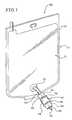
- FIG. 1illustrates a side-elevational view of an embodiment of the present invention showing a container implementing a connector of the present invention.
- FIG. 2illustrates a cross-sectional view of an embodiment of the present invention showing a first coupling member, a spike and a second coupling member in a first position.
- FIG. 3illustrates a cross-sectional view of an embodiment of the present invention showing the first coupling member, the spike and the second coupling member in a second position.
- FIG. 4illustrates a cross-sectional view of an embodiment of the present invention showing the first coupling member, the spike and the second coupling member in a third position.
- FIG. 5illustrates an exploded perspective view of an embodiment of the present invention showing the first coupling member, the spike and the second coupling member.
- the present inventiongenerally relates to a connector, a container using the connector and a method for establishing fluid communication with the container.
- the connectormay be implemented to provide access and/or fluid communication with medicaments within a container.
- the connectoris especially suitable for use with a container, such as a flexible bag.
- a containersuch as a flexible bag.
- the medicamentsmay be in liquid or solid form, such as, for example, a solution or suspension, or powdered or lyophilized, respectively.
- the connectormay include a first coupling member that may be attached to a container. Further, the connector may have a second coupling member that may be attached to a line that may direct the medicaments to a patient. A user may place the first coupling member and the second coupling member in a first position in which the first coupling member and the second coupling member are separate components. The user may secure the first coupling member to the second coupling member forming the connector and establishing fluid communication from the container through the connector.
- FIG. 1illustrates a container 10 in the form of a bag or any other container, such as, a vial or a bottle.
- the container 10is a flexible bag having a first wall 11 and a second wall 13 that hold the medicaments in the container 10 .
- the first wall 11 and the second wall 13may be sealed around an edge 15 of the container 10 .
- the container 10may have a first tube 12 that may project from the container 10 .
- the first tube 12may provide fluid communication between the container 10 and a first coupling member 14 .
- the first coupling member 14may have a first passageway 16 extending toward the container 10 .
- the first passageway 16may be attached to the first tube 12 to provide fluid communication between the container 10 and the first coupling member 14 .
- FIG. 2illustrates the first coupling member 14 and the second coupling member 28 . Fluid communication between the container 10 and the patient is not established in FIG. 2 since the first coupling member 14 and the second coupling member 28 are not connected.
- FIG. 2further illustrates a diameter 20 of the first passageway 16 .
- the diameter 20may be tapered toward a distal end 22 of the first passageway 16 to form an interference fit between the diameter 20 and the first tube 12 .
- the diameter 20 and the first tube 12may further be attached using, for example, the heat generated by autoclave sterilization or an adhesive.
- the first coupling member 14may have a first end 24 and a second end 26 defining a length of the first coupling member 14 .
- a second coupling member 28may attach to the second end 26 of the first coupling member 14 to establish fluid communication between the first coupling member 14 and the second coupling member 28 .
- Such fluid communicationmay be necessary for solution to flow from the container 10 through the first coupling member 14 , a spike 62 and the second coupling member 28 to a patient in, for example, a dialysis process.
- the first coupling member 14may have a first section 30 that may be integrally formed with the diameter 20 .
- the first section 30may cover the first passageway 16 .
- the first section 30may be the outside surface of the first coupling member 14 .
- the first section 30may be constructed from any material such as, for example, plastic or rubber.
- a flange 32 on the first coupling member 14may provide the user with an area to grip on the first coupling member 14 for connecting the first coupling member 14 to the second coupling member 28 .
- the first flange 32may be integrally molded with the first section 30 .
- the second coupling member 28may have a second section 54 that may be integrally formed with a second diameter 55 of the second passageway 48 .
- the second section 54may cover a portion of the second passageway 48 .
- the second section 54may be the outside surface of the second coupling member 28 .
- the second section 54may be constructed from any suitable material, such as, for example, plastic or rubber.
- the second section 54may have a flange 56 that may provide the user with an area to grip on the second coupling member 28 .
- the flange 56 on the second coupling member 28may be positioned at any point around the second section 54 .
- the flange 56is centrally located around the second section 54 .
- the second flange 56may be integrally formed with the second section 54 and an internal section 58 .
- FIG. 2also illustrates the first position wherein the first coupling member 14 and the second coupling member 28 are not connected to each other.
- the first coupling member 14 and the second coupling member 28may be in the first position before a user connects the first coupling member 14 and the second coupling member 28 .
- Fluid communication between the container 10 and the patientmay not be established in the first position.
- the first coupling member 14may have a first gap 39 between the first section 30 and the diameter 20 .
- the first gap 39may be an area defined within the first section 30 and the diameter 20 .
- the first gap 39may provide an area for expansion for the first coupling member 14 .
- the first coupling member 14may expand outward from the first section 30 during connection of the second coupling member 28 if the male end 44 is slightly larger than the female end 42 .
- the female end 42 of a luer-lock type connectormay be located at the second end 26 of the first coupling member 14 . Additionally, a male end 44 of a luer-lock type connector may be located at a first end 50 of the second coupling member 28 .
- the female end 42may threadingly engage the male end 44 to establish fluid communication between the first coupling member 14 , the spike 62 and the second coupling member 28 . More specifically, engagement of the first coupling member 14 to the second coupling member 28 forces the spike 62 to pierce the membrane 68 located in the first passageway 16 of the first coupling member 14 .
- the first passageway 16may be defined through the first coupling member 14 so the medicaments may flow through the first passageway 16 when the first coupling member 14 is connected to the second coupling member 28 .
- the second passageway 48may be defined through the second coupling member 28 so the medicaments may flow through the second passageway 48 when the first coupling member 14 is connected to the second coupling member 28 .
- connection of the first coupling member 14 to the second coupling member 28forces the spike 62 to pierce the membrane 68 in the first coupling member 14 . After the membrane 68 is pierced, fluid communication with the container 10 is established through the first coupling member 14 , the spike 62 and the second coupling member 28 .
- the internal section 58 of the second coupling member 28may be attached to a second diameter 55 of the second passageway 48 at a junction 60 .
- the junction 60may be integrally formed with the internal section 58 of the second coupling member 28 .
- the second coupling member 28also has a second gap 78 that may be defined between the internal section 58 and the male end 44 .
- the second gap 78may provide a space for the second end 26 of the first coupling member 14 to slide into the second coupling member 28 .
- the spike 62may be located in the first passageway 16 .
- the spike 62may be located in the second passageway 48 of the second coupling member 28 . Locating the spike 62 in the second passageway 48 of the second coupling member 28 instead of the first coupling member 14 may reduce surface contact of the spike 62 with the first passageway 16 and may, therefore, allow for effective steam sterilization of the spike 62 , the first coupling member 14 and the second coupling member 28 . Locating the spike 62 in the second passageway 48 of the second coupling member 28 may also eliminate the need for gamma sterilization.
- the spike 62may also be located in the second coupling member 28 .
- the spike 62is hollow so that solution may flow through the spike 62 when the first coupling member 14 and the second coupling member 28 are connected.
- the spike 62may have a base 64 that may be abutted by the male end 44 while connecting the first coupling member 14 and the second coupling member 28 .
- the spike 62may pierce the membrane 68 by twisting the first coupling member 14 and the second coupling member 28 .
- the membrane 68may prevent medicaments from exiting the container 10 through the first passageway 16 of the first coupling member 14 .
- the membrane 68may prevent fluid or other solution or medicaments from exiting the container 10 through the first passageway 16 of the first coupling member 14 until the spike 62 pierces the membrane 68 .
- the membrane 68may have a score line (not shown) that may allow the spike 62 to pierce the membrane 68 . To this end, the score line may act as a target to which the spike 62 is directed and piercing of the membrane 68 may be effected accurately and precisely.
- the membrane 68may be made any from suitable material, such as, for example, rubber or cellophane.
- a flange 66 on the spike 62may prevent the spike 62 from entering the first passageway 16 .
- the spike 62may slide into the first passageway 16 to pierce the membrane 68 .
- the membrane 68may prevent leaking of the medicaments from the container 10 prior to establishing fluid communication. After the membrane 68 is pierced by the spike 62 , fluid communication may be established from the container 10 , through the first coupling member 14 and the spike 62 and through the second coupling member 28 .
- the flange 66 on the spike 62may be located around an outer diameter of the spike 62 and may be integrally formed with the spike 62 .
- a lip 67 between the distal end 22 and the female end 42may prevent the spike 62 from entering the first passageway 16 .
- the lip 67may be integrally formed with the inner diameter 18 and may protrude from the inner diameter 18 .
- the lip 67may prohibit the passage of the spike 62 over the lip 67 through the flange 66 on the spike 62 .
- the lip 67may be a distance from the female end 42 such that the spike 62 may slidably pierce the membrane 68 without entering the first passageway 16 .
- FIG. 2further illustrates a first cap 72 and a second cap 74 that may prevent objects from making contact with the second end 26 of the first coupling member 14 and the first end 50 of the second coupling member 28 , respectively.
- the first cap 72 and the second cap 74may further preserve the sterility of the second end 26 of the first coupling member 14 and the first end 50 of the second coupling member 28 , respectively.
- the first cap 72 and the second cap 74may be constructed from any suitable material, such as, for example, plastic.
- the first cap 72may be removed from the first coupling member 14 prior to connecting the first coupling member 14 and the second coupling member 28 .
- the second cap 74may be removed from the second coupling member 28 prior to connecting the second coupling member 28 to the first coupling member 14 .
- FIG. 3illustrates the first coupling member 14 and the second coupling member 28 wherein a user may abut the female end 42 and the male end 44 .
- a usermay guide the second end 26 of the first coupling member 14 into the second coupling member 28 .
- the second end 26 of the first coupling member 14may slide into the second gap 78 of the first end 50 of the second coupling member 28 .
- the second end 26may slide into the second gap 78 so that alignment of the first coupling member 14 and the second coupling member 28 is not askew prior to connection and piercing of the membrane 68 following attachment of the first coupling member 14 to the second coupling member 28 .
- FIG. 4illustrates a position wherein the first coupling member 14 , the spike 62 and the second coupling member 28 are connected. Fluid communication from the container 10 through the first coupling member 14 , the spike 62 and the second coupling member 28 may be established when a user “twists” the first coupling member 14 and the second coupling member 28 . Twisting the first coupling member 14 to connect to the second coupling member 28 , allows engagement and may connect the female end 42 of the first coupling member 14 to the male end 44 of the second coupling member 28 . The female end 42 and the male end 44 may engage using a luer-lock connection. Fluid communication from the container 10 through the first coupling member 14 , the spike 62 and the second coupling member 28 may be established in the position shown in FIG. 4 .
- Connecting of the first coupling member 14 with the second coupling member 28may produce a physical and/or audible confirmation that the membrane 68 has been pierced and/or that fluid communication may be established. More specifically, an audible “pop” may be heard when the pressure of the spike 62 is great enough to rupture the membrane 68 . Additionally, once the membrane 68 is pierced, the torque required to push the spike 62 into the membrane 68 is reduced, creating a physical confirmation that the membrane 68 has been pierced. The physical and/or audible confirmation may aid patients who suffer from, for example, poor vision or other disabilities associated with, for example, renal disease.
- the medicamentsmay pass through the first coupling member 14 , the spike 62 and the second coupling member 28 through the first passageway 16 and the second passageway 48 .
- the first passageway 16 and the second passageway 48may establish fluid communication from the container 10 through the first coupling member 14 , the spike 62 and the second coupling member 28 .
- the first passageway 16 and the second passageway 48may extend from the distal end 22 of the first coupling member 14 to a second end 52 of the second coupling member 28 .
- Connecting the first coupling member 14 to the second coupling member 28may cause the spike 62 to pierce the membrane 68 with a tip 70 of the spike 62 .
- the base 64 of the spike 62may be advanced toward the membrane 68 by the male end 44 .
- the tip 70may pierce the membrane 68 after the base 64 of the spike 62 is advanced toward the membrane 68 by the male end 44 .
- the membrane 68may have a score line that may simplify piercing of the membrane 68 .
- FIG. 5illustrates the first coupling member 14 , the spike 62 and the second coupling member 28 .
- the spike 62may be inserted into the first coupling member 14 though the female end 42 . In this manner, the spike 62 may pierce the membrane 68 when the first coupling member 14 and the second coupling member 28 are connected.
- connection of the female end 42 and the male end 44advances the spike 62 through the first passageway 16 to pierce the membrane 68 .
- Connecting the first coupling member 14 and the second coupling member 28causes the first end 50 of the second coupling member 28 to force the base 64 toward the membrane 68 .
- the tip 70may pierce the membrane 68 , which may form the passageway 38 through the first coupling member 14 and the second coupling member 28 .
- the flange 66 on the spike 62may prevent the spike 62 from advancing beyond the lip 67 and into the first tube 12 .
- a mistake-proof connectionmay be established. Namely, a user may readily identify when the first coupling member 14 is connected to the second coupling member 28 . Likewise, a user may know when the first coupling member 14 is not connected to the second coupling member 28 . Further, a user may identify when the first coupling member 14 and the second coupling member 28 are connected. Namely, the construction of the connector allows a user to identify if the first coupling member 14 and the second coupling member 28 are connected to establish fluid communication. Moreover, a user may “feel” the piercing of the membrane 68 during connection of the first coupling member 14 and the second coupling member 28 .
- a usermay connect the first coupling member 14 to the second coupling member 28 to establish fluid communication from the container 10 to a patient. Fluid communication may be established from the container 10 , through the first coupling member 14 , the spike 62 and the second coupling member 28 , to the patient following connection as a result of the membrane 68 in the first coupling member 14 being pierced by the spike 62 also in the first coupling member 14 .
Landscapes
- Health & Medical Sciences (AREA)
- Hematology (AREA)
- Heart & Thoracic Surgery (AREA)
- Life Sciences & Earth Sciences (AREA)
- Animal Behavior & Ethology (AREA)
- General Health & Medical Sciences (AREA)
- Public Health (AREA)
- Veterinary Medicine (AREA)
- Epidemiology (AREA)
- Pharmacology & Pharmacy (AREA)
- Pulmonology (AREA)
- Engineering & Computer Science (AREA)
- Anesthesiology (AREA)
- Biomedical Technology (AREA)
- Medical Preparation Storing Or Oral Administration Devices (AREA)
- Quick-Acting Or Multi-Walled Pipe Joints (AREA)
- Infusion, Injection, And Reservoir Apparatuses (AREA)
Abstract
Description
Claims (21)
Priority Applications (7)
| Application Number | Priority Date | Filing Date | Title |
|---|---|---|---|
| US10/173,890US6874522B2 (en) | 2002-06-18 | 2002-06-18 | Luer-actuated solution path connector with membrane and container using the connector and a method for establishing fluid communication with the container |
| EP03731547AEP1517723B1 (en) | 2002-06-18 | 2003-05-28 | Luer-actuated connector with membrane and container using the connector |
| PCT/US2003/017619WO2003105944A1 (en) | 2002-06-18 | 2003-05-28 | Luer-actuated connector with membrane and container using the connector |
| AU2003240535AAU2003240535A1 (en) | 2002-06-18 | 2003-05-28 | Luer-actuated connector with membrane and container using the connector |
| DE2003610935DE60310935T2 (en) | 2002-06-18 | 2003-05-28 | ACTIVE LUER CONNECTION WITH MEMBRANE AND CONTAINER CONNECTED |
| JP2004512843AJP2005529688A (en) | 2002-06-18 | 2003-05-28 | Luer actuating connector with membrane and container using this connector |
| MXPA04012751AMXPA04012751A (en) | 2002-06-18 | 2003-05-28 | Luer-actuated connector with membrane and container using the connector. |
Applications Claiming Priority (1)
| Application Number | Priority Date | Filing Date | Title |
|---|---|---|---|
| US10/173,890US6874522B2 (en) | 2002-06-18 | 2002-06-18 | Luer-actuated solution path connector with membrane and container using the connector and a method for establishing fluid communication with the container |
Publications (2)
| Publication Number | Publication Date |
|---|---|
| US20030230340A1 US20030230340A1 (en) | 2003-12-18 |
| US6874522B2true US6874522B2 (en) | 2005-04-05 |
Family
ID=29733444
Family Applications (1)
| Application Number | Title | Priority Date | Filing Date |
|---|---|---|---|
| US10/173,890Expired - LifetimeUS6874522B2 (en) | 2002-06-18 | 2002-06-18 | Luer-actuated solution path connector with membrane and container using the connector and a method for establishing fluid communication with the container |
Country Status (7)
| Country | Link |
|---|---|
| US (1) | US6874522B2 (en) |
| EP (1) | EP1517723B1 (en) |
| JP (1) | JP2005529688A (en) |
| AU (1) | AU2003240535A1 (en) |
| DE (1) | DE60310935T2 (en) |
| MX (1) | MXPA04012751A (en) |
| WO (1) | WO2003105944A1 (en) |
Cited By (39)
| Publication number | Priority date | Publication date | Assignee | Title |
|---|---|---|---|---|
| US20040116869A1 (en)* | 2002-10-15 | 2004-06-17 | Transcoject Gesellschaft Fur Medizinische Gerate Mbh & Co. Kg | Membrane syringe |
| US20050017503A1 (en)* | 2003-07-23 | 2005-01-27 | Garry Tsaur | Connector with frangible seal |
| US20080185056A1 (en)* | 2007-02-01 | 2008-08-07 | Saint-Gobain Performance Plastics Corporation | Connector assembly |
| US20090036861A1 (en)* | 2007-08-01 | 2009-02-05 | Hospira, Inc. | Medicament admixing system |
| US20090232586A1 (en)* | 2007-02-01 | 2009-09-17 | Saint-Gobain Performance Plastics Corporation | Connector assembly |
| USD601660S1 (en) | 2006-04-14 | 2009-10-06 | Johnsondiversey, Inc. | Lock-out closure for a container with a corresponding lock-out dispenser insert |
| US20090326481A1 (en)* | 2008-06-30 | 2009-12-31 | Tyco Healthcare Group Lp | Discriminating oral-tip adaptor |
| US20100022986A1 (en)* | 2006-09-04 | 2010-01-28 | Barbara Breuer-Thal | Multi-purpose connector for enteral application |
| US7753338B2 (en) | 2006-10-23 | 2010-07-13 | Baxter International Inc. | Luer activated device with minimal fluid displacement |
| US20100283238A1 (en)* | 2009-05-11 | 2010-11-11 | Tyco Healthcare Group Lp | Discriminating Fluid Connection System |
| US7981090B2 (en) | 2006-10-18 | 2011-07-19 | Baxter International Inc. | Luer activated device |
| US8221363B2 (en) | 2006-10-18 | 2012-07-17 | Baxter Healthcare S.A. | Luer activated device with valve element under tension |
| US8414555B2 (en) | 2008-05-14 | 2013-04-09 | J & J Solutions, Inc. | Systems and methods for safe medicament transport |
| US8562582B2 (en) | 2006-05-25 | 2013-10-22 | Bayer Healthcare Llc | Reconstitution device |
| CN103569295A (en)* | 2012-08-03 | 2014-02-12 | 株式会社岛野 | Hydraulic bicycle component set |
| US8721612B2 (en) | 2010-12-17 | 2014-05-13 | Hospira, Inc. | System and method for intermixing the contents of two containers |
| US8834444B2 (en) | 2011-10-03 | 2014-09-16 | Hospira, Inc. | System and method for mixing the contents of two containers |
| US9107809B2 (en) | 2010-05-27 | 2015-08-18 | J & J Solutions, Inc. | Closed fluid transfer system |
| US9227692B2 (en) | 2012-08-03 | 2016-01-05 | Shimano Inc. | Hydraulic bicycle component system |
| US20160003393A1 (en)* | 2013-02-20 | 2016-01-07 | Fisher & Paykel Healthcare Limited | Connector for multiple sized connections |
| TWI565621B (en)* | 2012-08-03 | 2017-01-11 | 島野股份有限公司 | Hydraulic bicycle component |
| US9550546B2 (en)* | 2012-08-03 | 2017-01-24 | Shimano Inc. | Hydraulic bicycle hose structure |
| US9877895B2 (en) | 2013-08-02 | 2018-01-30 | J&J Solutions, Inc. | Compounding systems and methods for safe medicament transport |
| USD907193S1 (en) | 2018-02-21 | 2021-01-05 | Eli Lilly And Company | Secured medication transfer set |
| US10888496B2 (en) | 2015-09-17 | 2021-01-12 | Corvida Medical, Inc. | Medicament vial assembly |
| US10894317B2 (en) | 2015-10-13 | 2021-01-19 | Corvida Medical, Inc. | Automated compounding equipment for closed fluid transfer system |
| US11143336B1 (en)* | 2017-11-13 | 2021-10-12 | Tbl Performance Plastics, Llc | Connector, method of making connector and tubing assembly method |
| US11415255B1 (en) | 2020-03-31 | 2022-08-16 | Colder Products Company | Aseptic fluid couplings |
| US11590333B2 (en) | 2018-01-22 | 2023-02-28 | Saint-Gobain Performance Plastics Corporation | Tubular coupling |
| US11602607B2 (en) | 2014-09-24 | 2023-03-14 | Fisher & Paykel Healthcare Limited | Swivel connector |
| US11674614B2 (en) | 2020-10-09 | 2023-06-13 | Icu Medical, Inc. | Fluid transfer device and method of use for same |
| US11730678B2 (en) | 2016-08-22 | 2023-08-22 | Eli Lilly And Company | Secured medication transfer system |
| US12072049B2 (en) | 2020-06-26 | 2024-08-27 | Carefusion 303, Inc. | Connector coupling assembly |
| US12109387B2 (en) | 2022-11-11 | 2024-10-08 | Carefusion 303, Inc. | Connector coupling assembly |
| US12186518B2 (en) | 2023-04-25 | 2025-01-07 | Carefusion 303, Inc. | Fluid connector system |
| US12208230B2 (en) | 2022-11-09 | 2025-01-28 | Carefusion 303, Inc. | Fluid connector assembly that seals flow paths when the connectors are disconnected |
| US12208231B2 (en) | 2021-06-30 | 2025-01-28 | Carefusion 303, Inc. | Fluid connector system |
| US12403295B2 (en) | 2022-08-11 | 2025-09-02 | Carefusion 303, Inc. | Fluid connector system |
| US12420074B2 (en) | 2023-07-13 | 2025-09-23 | Carefusion 303, Inc. | Fluid connector assembly |
Families Citing this family (7)
| Publication number | Priority date | Publication date | Assignee | Title |
|---|---|---|---|---|
| US8540698B2 (en)* | 2004-04-16 | 2013-09-24 | Medrad, Inc. | Fluid delivery system including a fluid path set and a check valve connector |
| US20070161970A1 (en) | 2004-04-16 | 2007-07-12 | Medrad, Inc. | Fluid Delivery System, Fluid Path Set, and Pressure Isolation Mechanism with Hemodynamic Pressure Dampening Correction |
| GB0224785D0 (en)* | 2002-10-24 | 2002-12-04 | Guest John Int Ltd | Temporary closure devices and tube couplings incorporating such devices |
| US8460228B2 (en) | 2009-10-27 | 2013-06-11 | Nxstage Medical Inc. | Methods, devices, and systems for parallel control of infusion device |
| WO2011127074A1 (en)* | 2010-04-05 | 2011-10-13 | Py Daniel C | Aseptic connector with deflectable ring of concern and method |
| DE102017211793A1 (en) | 2017-07-10 | 2019-01-10 | Gustav Magenwirth Gmbh & Co. Kg | Hydraulic line connection for a hydraulic brake handlebar guided vehicles, hydraulic line connection and hydraulic component fixing device for a hydraulic actuator handlebar guided vehicles, handlebar assembly for a handlebar-guided vehicle and hydraulic brake for a handlebar-guided vehicle |
| DE102017116394A1 (en) | 2017-07-20 | 2019-01-24 | B. Braun Avitum Ag | Disposal container for used dialysis fluid and extracorporeal blood purification system with such a disposal container |
Citations (30)
| Publication number | Priority date | Publication date | Assignee | Title |
|---|---|---|---|---|
| US3202442A (en)* | 1961-05-19 | 1965-08-24 | Aeroquip Corp | Coupling |
| US3285627A (en)* | 1964-02-10 | 1966-11-15 | Weatherhead Co | Pipe coupling |
| US3844585A (en)* | 1973-07-10 | 1974-10-29 | Mueller Co | Pipe coupling |
| US4022205A (en) | 1973-11-05 | 1977-05-10 | Tenczar Francis J | Fluid connectors |
| US4217897A (en) | 1975-06-30 | 1980-08-19 | Sneider Vincent R | Expandable syringe and means for storing chemical agents for use therewith |
| US4331146A (en)* | 1976-12-23 | 1982-05-25 | The West Company | Syringe assembly |
| EP0157224A2 (en) | 1984-03-31 | 1985-10-09 | Intermedicat Gmbh | Connection device |
| US4636204A (en) | 1982-04-13 | 1987-01-13 | Gambro Lundia Ab | Coupling for the connection of flexible tubes and the like |
| US4883473A (en) | 1987-04-29 | 1989-11-28 | Path | Single use injection device |
| US4886497A (en) | 1988-01-22 | 1989-12-12 | Scholl Jr Charles W | Disposable protective container for hypodermic syringes |
| US5106127A (en)* | 1989-12-27 | 1992-04-21 | Hutchinson | Rapid connection fluid coupling |
| US5176415A (en) | 1990-08-16 | 1993-01-05 | Choksi Pradip V | Taper fitting with protective skirt |
| US5190521A (en) | 1990-08-22 | 1993-03-02 | Tecnol Medical Products, Inc. | Apparatus and method for raising a skin wheal and anesthetizing skin |
| US5336192A (en) | 1991-11-27 | 1994-08-09 | Palestrant Aubrey M | Self-sealing valve device for angiographic catheters |
| EP0611223A1 (en) | 1993-01-11 | 1994-08-17 | Hospal Ag | Connector between container and conduit for medical liquids |
| US5501676A (en) | 1995-01-13 | 1996-03-26 | Sanofi Winthrop, Inc. | Coupling system for safety cannula |
| US5554130A (en) | 1995-05-17 | 1996-09-10 | Creative Bio Tech, Inc. | Stick-free syringe and associated methods |
| US5669891A (en) | 1994-10-24 | 1997-09-23 | Vaillancourt; Vincent L. | Female luer connector |
| EP0830874A2 (en) | 1996-09-17 | 1998-03-25 | Fresenius AG | Connector device for medical use |
| US5772625A (en) | 1996-11-19 | 1998-06-30 | Heyer-Schulte Neurocare, Inc. | External drainage shunt |
| US5817082A (en)* | 1996-11-08 | 1998-10-06 | Bracco Diagnostics Inc. | Medicament container closure with integral spike access means |
| US5891129A (en)* | 1997-02-28 | 1999-04-06 | Abbott Laboratories | Container cap assembly having an enclosed penetrator |
| US5895383A (en) | 1996-11-08 | 1999-04-20 | Bracco Diagnostics Inc. | Medicament container closure with recessed integral spike access means |
| US5897526A (en) | 1996-06-26 | 1999-04-27 | Vaillancourt; Vincent L. | Closed system medication administering system |
| US5902298A (en)* | 1997-11-07 | 1999-05-11 | Bracco Research Usa | Medicament container stopper with integral spike access means |
| US6003566A (en)* | 1998-02-26 | 1999-12-21 | Becton Dickinson And Company | Vial transferset and method |
| US6070623A (en)* | 1996-09-25 | 2000-06-06 | Biodome | Connecting device, in particular between a receptacle with a stopper capable of being perforated and a syringe |
| US6171287B1 (en) | 1998-05-29 | 2001-01-09 | Lawrence A. Lynn | Luer receiver and method for fluid transfer |
| US6382442B1 (en)* | 1998-04-20 | 2002-05-07 | Becton Dickinson And Company | Plastic closure for vials and other medical containers |
| US6695829B2 (en)* | 1996-04-22 | 2004-02-24 | Abbott Laboratories | Container closure system |
- 2002
- 2002-06-18USUS10/173,890patent/US6874522B2/ennot_activeExpired - Lifetime
- 2003
- 2003-05-28DEDE2003610935patent/DE60310935T2/ennot_activeExpired - Lifetime
- 2003-05-28JPJP2004512843Apatent/JP2005529688A/enactivePending
- 2003-05-28WOPCT/US2003/017619patent/WO2003105944A1/enactiveIP Right Grant
- 2003-05-28AUAU2003240535Apatent/AU2003240535A1/ennot_activeAbandoned
- 2003-05-28MXMXPA04012751Apatent/MXPA04012751A/enactiveIP Right Grant
- 2003-05-28EPEP03731547Apatent/EP1517723B1/ennot_activeExpired - Lifetime
Patent Citations (32)
| Publication number | Priority date | Publication date | Assignee | Title |
|---|---|---|---|---|
| US3202442A (en)* | 1961-05-19 | 1965-08-24 | Aeroquip Corp | Coupling |
| US3285627A (en)* | 1964-02-10 | 1966-11-15 | Weatherhead Co | Pipe coupling |
| US3844585A (en)* | 1973-07-10 | 1974-10-29 | Mueller Co | Pipe coupling |
| US4022205A (en) | 1973-11-05 | 1977-05-10 | Tenczar Francis J | Fluid connectors |
| US4217897A (en) | 1975-06-30 | 1980-08-19 | Sneider Vincent R | Expandable syringe and means for storing chemical agents for use therewith |
| US4331146A (en)* | 1976-12-23 | 1982-05-25 | The West Company | Syringe assembly |
| US4636204A (en) | 1982-04-13 | 1987-01-13 | Gambro Lundia Ab | Coupling for the connection of flexible tubes and the like |
| EP0157224A2 (en) | 1984-03-31 | 1985-10-09 | Intermedicat Gmbh | Connection device |
| US4883473A (en) | 1987-04-29 | 1989-11-28 | Path | Single use injection device |
| US4886497A (en) | 1988-01-22 | 1989-12-12 | Scholl Jr Charles W | Disposable protective container for hypodermic syringes |
| US5106127A (en)* | 1989-12-27 | 1992-04-21 | Hutchinson | Rapid connection fluid coupling |
| US5176415A (en) | 1990-08-16 | 1993-01-05 | Choksi Pradip V | Taper fitting with protective skirt |
| US5190521A (en) | 1990-08-22 | 1993-03-02 | Tecnol Medical Products, Inc. | Apparatus and method for raising a skin wheal and anesthetizing skin |
| US5336192A (en) | 1991-11-27 | 1994-08-09 | Palestrant Aubrey M | Self-sealing valve device for angiographic catheters |
| EP0611223A1 (en) | 1993-01-11 | 1994-08-17 | Hospal Ag | Connector between container and conduit for medical liquids |
| US5669891A (en) | 1994-10-24 | 1997-09-23 | Vaillancourt; Vincent L. | Female luer connector |
| US5501676A (en) | 1995-01-13 | 1996-03-26 | Sanofi Winthrop, Inc. | Coupling system for safety cannula |
| US5554130A (en) | 1995-05-17 | 1996-09-10 | Creative Bio Tech, Inc. | Stick-free syringe and associated methods |
| US6695829B2 (en)* | 1996-04-22 | 2004-02-24 | Abbott Laboratories | Container closure system |
| US5897526A (en) | 1996-06-26 | 1999-04-27 | Vaillancourt; Vincent L. | Closed system medication administering system |
| EP0830874A2 (en) | 1996-09-17 | 1998-03-25 | Fresenius AG | Connector device for medical use |
| US6070623A (en)* | 1996-09-25 | 2000-06-06 | Biodome | Connecting device, in particular between a receptacle with a stopper capable of being perforated and a syringe |
| US5817082A (en)* | 1996-11-08 | 1998-10-06 | Bracco Diagnostics Inc. | Medicament container closure with integral spike access means |
| US5895383A (en) | 1996-11-08 | 1999-04-20 | Bracco Diagnostics Inc. | Medicament container closure with recessed integral spike access means |
| US5772625A (en) | 1996-11-19 | 1998-06-30 | Heyer-Schulte Neurocare, Inc. | External drainage shunt |
| US5891129A (en)* | 1997-02-28 | 1999-04-06 | Abbott Laboratories | Container cap assembly having an enclosed penetrator |
| US5954104A (en) | 1997-02-28 | 1999-09-21 | Abbott Laboratories | Container cap assembly having an enclosed penetrator |
| US5902298A (en)* | 1997-11-07 | 1999-05-11 | Bracco Research Usa | Medicament container stopper with integral spike access means |
| US6003566A (en)* | 1998-02-26 | 1999-12-21 | Becton Dickinson And Company | Vial transferset and method |
| US6189580B1 (en) | 1998-02-26 | 2001-02-20 | Becton, Dickinson And Company | Vial transferset and method |
| US6382442B1 (en)* | 1998-04-20 | 2002-05-07 | Becton Dickinson And Company | Plastic closure for vials and other medical containers |
| US6171287B1 (en) | 1998-05-29 | 2001-01-09 | Lawrence A. Lynn | Luer receiver and method for fluid transfer |
Cited By (86)
| Publication number | Priority date | Publication date | Assignee | Title |
|---|---|---|---|---|
| US7367964B2 (en)* | 2002-10-15 | 2008-05-06 | Transcoject Gesellschaft für medizinische Geräte mbH & Co. KG | Membrane syringe with cap |
| US20040116869A1 (en)* | 2002-10-15 | 2004-06-17 | Transcoject Gesellschaft Fur Medizinische Gerate Mbh & Co. Kg | Membrane syringe |
| US20050017503A1 (en)* | 2003-07-23 | 2005-01-27 | Garry Tsaur | Connector with frangible seal |
| USD619681S1 (en) | 2006-04-14 | 2010-07-13 | Diversey, Inc. | Closure for a container |
| USD646754S1 (en) | 2006-04-14 | 2011-10-11 | Diversey, Inc. | Insert for a closure for a container |
| USD629870S1 (en) | 2006-04-14 | 2010-12-28 | Diversey, Inc. | Closure for a container |
| USD601660S1 (en) | 2006-04-14 | 2009-10-06 | Johnsondiversey, Inc. | Lock-out closure for a container with a corresponding lock-out dispenser insert |
| USD602120S1 (en) | 2006-04-14 | 2009-10-13 | Johnsondiversey, Inc. | Lock-out closure for a container with a corresponding lock-out dispenser insert |
| US9522098B2 (en) | 2006-05-25 | 2016-12-20 | Bayer Healthcare, Llc | Reconstitution device |
| US8562582B2 (en) | 2006-05-25 | 2013-10-22 | Bayer Healthcare Llc | Reconstitution device |
| US20100022986A1 (en)* | 2006-09-04 | 2010-01-28 | Barbara Breuer-Thal | Multi-purpose connector for enteral application |
| US8506549B2 (en)* | 2006-09-04 | 2013-08-13 | Fresenius Kabi Deutschland Gmbh | Multi-purpose connector for enteral application |
| US7981090B2 (en) | 2006-10-18 | 2011-07-19 | Baxter International Inc. | Luer activated device |
| US8221363B2 (en) | 2006-10-18 | 2012-07-17 | Baxter Healthcare S.A. | Luer activated device with valve element under tension |
| US7753338B2 (en) | 2006-10-23 | 2010-07-13 | Baxter International Inc. | Luer activated device with minimal fluid displacement |
| US20090232586A1 (en)* | 2007-02-01 | 2009-09-17 | Saint-Gobain Performance Plastics Corporation | Connector assembly |
| US20080185056A1 (en)* | 2007-02-01 | 2008-08-07 | Saint-Gobain Performance Plastics Corporation | Connector assembly |
| US7918243B2 (en) | 2007-02-01 | 2011-04-05 | Saint-Gobain Performance Plastics Corporation | Connector assembly |
| US8899267B2 (en)* | 2007-02-01 | 2014-12-02 | Saint-Gobain Performance Plastics Corporation | Connector assembly |
| US9205025B2 (en) | 2007-08-01 | 2015-12-08 | Hospira, Inc. | Medicament admixing system |
| US9205026B2 (en) | 2007-08-01 | 2015-12-08 | Hospira, Inc. | Medicament admixing system |
| US8801689B2 (en) | 2007-08-01 | 2014-08-12 | Hospira, Inc. | Medicament admixing system |
| US20090036861A1 (en)* | 2007-08-01 | 2009-02-05 | Hospira, Inc. | Medicament admixing system |
| US9198832B2 (en) | 2007-08-01 | 2015-12-01 | Hospira, Inc. | Medicament admixing system |
| US10058483B2 (en) | 2008-05-14 | 2018-08-28 | J&J Solutions, Inc. | Systems and methods for safe medicament transport |
| US10966905B2 (en) | 2008-05-14 | 2021-04-06 | Corvida Medical, Inc. | Systems and methods for safe medicament transport |
| US9220661B2 (en) | 2008-05-14 | 2015-12-29 | J & J Solutions, Inc. | Systems and methods for safe medicament transport |
| US8469940B2 (en) | 2008-05-14 | 2013-06-25 | J & J Solutions, Inc. | Systems and methods for safe medicament transport |
| US8414556B2 (en) | 2008-05-14 | 2013-04-09 | J & J Solutions, Inc. | Systems and methods for safe medicament transport |
| US8414554B2 (en) | 2008-05-14 | 2013-04-09 | J & J Solutions, Inc. | Systems and methods for safe medicament transport |
| US8894627B2 (en) | 2008-05-14 | 2014-11-25 | J & J Solutions, Inc. | Systems and methods for safe medicament transport |
| US8414555B2 (en) | 2008-05-14 | 2013-04-09 | J & J Solutions, Inc. | Systems and methods for safe medicament transport |
| US8777930B2 (en) | 2008-06-30 | 2014-07-15 | Covidien Lp | Discriminating oral-tip adaptor |
| US20090326481A1 (en)* | 2008-06-30 | 2009-12-31 | Tyco Healthcare Group Lp | Discriminating oral-tip adaptor |
| US8684979B2 (en) | 2009-05-11 | 2014-04-01 | Covidien Lp | Discriminating fluid connection system |
| US20100283238A1 (en)* | 2009-05-11 | 2010-11-11 | Tyco Healthcare Group Lp | Discriminating Fluid Connection System |
| US9351906B2 (en) | 2010-05-27 | 2016-05-31 | J & J Solutions, Inc. | Closed fluid transfer system with syringe adapter |
| US10238576B2 (en) | 2010-05-27 | 2019-03-26 | J & J Solutions, Inc. | Closed fluid transfer system |
| US9381137B2 (en) | 2010-05-27 | 2016-07-05 | J & J Solutions, Inc. | Closed fluid transfer system with syringe adapter |
| US9370466B2 (en) | 2010-05-27 | 2016-06-21 | J&J Solutions, Inc. | Closed fluid transfer system with syringe adapter |
| US9364396B2 (en) | 2010-05-27 | 2016-06-14 | J & J Solutions, Inc. | Closed fluid transfer system with syringe adapter |
| US9107809B2 (en) | 2010-05-27 | 2015-08-18 | J & J Solutions, Inc. | Closed fluid transfer system |
| US9358182B2 (en) | 2010-05-27 | 2016-06-07 | J & J Solutions, Inc. | Closed fluid transfer system with syringe adapter |
| US11219577B2 (en) | 2010-05-27 | 2022-01-11 | Corvida Medical, Inc. | Closed fluid transfer system |
| US8721612B2 (en) | 2010-12-17 | 2014-05-13 | Hospira, Inc. | System and method for intermixing the contents of two containers |
| US9610223B2 (en) | 2010-12-17 | 2017-04-04 | Hospira, Inc. | System and method for intermixing the contents of two containers |
| US8834444B2 (en) | 2011-10-03 | 2014-09-16 | Hospira, Inc. | System and method for mixing the contents of two containers |
| US8882739B2 (en) | 2011-10-03 | 2014-11-11 | Hospira, Inc. | System and method for mixing the contents of two containers |
| US8911421B2 (en) | 2011-10-03 | 2014-12-16 | Hospira, Inc. | System and method for mixing the contents of two containers |
| US9079686B2 (en) | 2011-10-03 | 2015-07-14 | Hospira, Inc. | Port assembly for mixing the contents of two containers |
| US9227692B2 (en) | 2012-08-03 | 2016-01-05 | Shimano Inc. | Hydraulic bicycle component system |
| US10272895B2 (en) | 2012-08-03 | 2019-04-30 | Shimano Inc. | Hydraulic bicycle component |
| US9550546B2 (en)* | 2012-08-03 | 2017-01-24 | Shimano Inc. | Hydraulic bicycle hose structure |
| CN103569295B (en)* | 2012-08-03 | 2016-12-28 | 株式会社岛野 | Hydraulic bicycle component set |
| TWI508891B (en)* | 2012-08-03 | 2015-11-21 | Shimano Kk | Hydraulic bicycle component kit |
| TWI565621B (en)* | 2012-08-03 | 2017-01-11 | 島野股份有限公司 | Hydraulic bicycle component |
| CN103569295A (en)* | 2012-08-03 | 2014-02-12 | 株式会社岛野 | Hydraulic bicycle component set |
| US10131339B2 (en) | 2012-08-03 | 2018-11-20 | Shimano Inc. | Hydraulic bicycle component |
| US9199691B2 (en) | 2012-08-03 | 2015-12-01 | Shimano Inc. | Hydraulic bicycle component kit |
| US10823319B2 (en) | 2013-02-20 | 2020-11-03 | Fisher & Paykel Healthcare Limited | Connector for multiple sized connections |
| US20160003393A1 (en)* | 2013-02-20 | 2016-01-07 | Fisher & Paykel Healthcare Limited | Connector for multiple sized connections |
| US11639764B2 (en) | 2013-02-20 | 2023-05-02 | Fisher & Paykel Healthcare Limited | Connector for multiple sized connections |
| US12181088B2 (en) | 2013-02-20 | 2024-12-31 | Fisher & Paykel Healthcare Limited | Connector for multiple sized connections |
| US10006573B2 (en)* | 2013-02-20 | 2018-06-26 | Fisher & Paykel Healthcare Limited | Connector for multiple sized connections |
| US9877895B2 (en) | 2013-08-02 | 2018-01-30 | J&J Solutions, Inc. | Compounding systems and methods for safe medicament transport |
| US11602607B2 (en) | 2014-09-24 | 2023-03-14 | Fisher & Paykel Healthcare Limited | Swivel connector |
| US10888496B2 (en) | 2015-09-17 | 2021-01-12 | Corvida Medical, Inc. | Medicament vial assembly |
| US10894317B2 (en) | 2015-10-13 | 2021-01-19 | Corvida Medical, Inc. | Automated compounding equipment for closed fluid transfer system |
| US12336966B2 (en) | 2016-08-22 | 2025-06-24 | Eli Lilly And Company | Secured medication transfer system |
| US11730678B2 (en) | 2016-08-22 | 2023-08-22 | Eli Lilly And Company | Secured medication transfer system |
| US11143336B1 (en)* | 2017-11-13 | 2021-10-12 | Tbl Performance Plastics, Llc | Connector, method of making connector and tubing assembly method |
| US11590333B2 (en) | 2018-01-22 | 2023-02-28 | Saint-Gobain Performance Plastics Corporation | Tubular coupling |
| USD907193S1 (en) | 2018-02-21 | 2021-01-05 | Eli Lilly And Company | Secured medication transfer set |
| USD990659S1 (en) | 2018-02-21 | 2023-06-27 | Eli Lilly And Company | Needle hub |
| USD997341S1 (en) | 2018-02-21 | 2023-08-29 | Eli Lilly And Company | Secured medication transfer set |
| US11415255B1 (en) | 2020-03-31 | 2022-08-16 | Colder Products Company | Aseptic fluid couplings |
| US12338931B2 (en) | 2020-03-31 | 2025-06-24 | Colder Products Company | Aseptic fluid couplings |
| US12072049B2 (en) | 2020-06-26 | 2024-08-27 | Carefusion 303, Inc. | Connector coupling assembly |
| US11674614B2 (en) | 2020-10-09 | 2023-06-13 | Icu Medical, Inc. | Fluid transfer device and method of use for same |
| US12345352B2 (en) | 2020-10-09 | 2025-07-01 | Icu Medical, Inc. | Fluid transfer device and method of use for same |
| US12208231B2 (en) | 2021-06-30 | 2025-01-28 | Carefusion 303, Inc. | Fluid connector system |
| US12403295B2 (en) | 2022-08-11 | 2025-09-02 | Carefusion 303, Inc. | Fluid connector system |
| US12208230B2 (en) | 2022-11-09 | 2025-01-28 | Carefusion 303, Inc. | Fluid connector assembly that seals flow paths when the connectors are disconnected |
| US12109387B2 (en) | 2022-11-11 | 2024-10-08 | Carefusion 303, Inc. | Connector coupling assembly |
| US12186518B2 (en) | 2023-04-25 | 2025-01-07 | Carefusion 303, Inc. | Fluid connector system |
| US12420074B2 (en) | 2023-07-13 | 2025-09-23 | Carefusion 303, Inc. | Fluid connector assembly |
Also Published As
| Publication number | Publication date |
|---|---|
| US20030230340A1 (en) | 2003-12-18 |
| EP1517723A1 (en) | 2005-03-30 |
| WO2003105944A1 (en) | 2003-12-24 |
| EP1517723B1 (en) | 2007-01-03 |
| DE60310935T2 (en) | 2007-10-18 |
| MXPA04012751A (en) | 2005-03-23 |
| DE60310935D1 (en) | 2007-02-15 |
| AU2003240535A1 (en) | 2003-12-31 |
| AU2003240535A8 (en) | 2003-12-31 |
| JP2005529688A (en) | 2005-10-06 |
Similar Documents
| Publication | Publication Date | Title |
|---|---|---|
| US6874522B2 (en) | Luer-actuated solution path connector with membrane and container using the connector and a method for establishing fluid communication with the container | |
| EP1415635B1 (en) | Sliding reconstitution device for a diluent container | |
| US5498253A (en) | Port adaptor and protector and container having same | |
| US6692478B1 (en) | Swabbable needleless vial access | |
| US9108031B2 (en) | Connector having a membrane, for connecting a syringe to a container or tubing | |
| US5580351A (en) | Pointed adapter for blunt entry device | |
| US6582415B1 (en) | Sliding reconstitution device for a diluent container | |
| EP0554988A1 (en) | Mixing apparatus | |
| US20040068239A1 (en) | Injection site for male luer or other tubular connector | |
| US5368586A (en) | Closure for a drug-vial | |
| EP0930904B1 (en) | Pharmaceutical ampul | |
| MXPA04009341A (en) | Sliding reconstitution device for a diluent container. | |
| JPH06239352A (en) | Solution injection set | |
| US20230248957A1 (en) | System comprising a cap for a medical fluid container and an attachment part, medical fluid container, and method for producing a fluid container | |
| US5738334A (en) | Diaphragm flow control assembly | |
| JP3070044B2 (en) | Infusion container with communication means | |
| JPS5975058A (en) | Infusion liquid instrument | |
| JP2003290362A (en) | Side injection tube | |
| EP0820777B1 (en) | System for the administration of substances by infusion | |
| US20230147763A1 (en) | Preassembled component for a connectable element assembly for the reconstitution of fluid drugs and nutrients with active substance in powder, liquid or gel form | |
| JP4056746B2 (en) | Syringe connection port | |
| JPH03267063A (en) | Plastic blow bag for liquid medicine | |
| CA1333704C (en) | Aseptic spike to luer fluid flow adapter | |
| AU2003204048B2 (en) | Sliding reconstitution device for a diluent container | |
| JP2003250910A (en) | Side injection pipe |
Legal Events
| Date | Code | Title | Description |
|---|---|---|---|
| AS | Assignment | Owner name:BAXTER INTERNATIONAL INC., ILLINOIS Free format text:ASSIGNMENT OF ASSIGNORS INTEREST;ASSIGNORS:ANDERSON, KEITH M.K.;CASTELLANOS, RAF;HURST, BILL;AND OTHERS;REEL/FRAME:013320/0921 Effective date:20020828 | |
| AS | Assignment | Owner name:BAXTER HEALTHCARE S.A., SWITZERLAND Free format text:ASSIGNMENT OF ASSIGNORS INTEREST;ASSIGNOR:BAXTER INTERNATIONAL INC.;REEL/FRAME:013615/0736 Effective date:20021218 Owner name:BAXTER INTERNATIONAL INC., ILLINOIS Free format text:ASSIGNMENT OF ASSIGNORS INTEREST;ASSIGNOR:BAXTER INTERNATIONAL INC.;REEL/FRAME:013615/0736 Effective date:20021218 | |
| AS | Assignment | Owner name:BAXTER INTERNATIONAL INC., ILLINOIS Free format text:ASSIGNMENT OF ASSIGNORS INTEREST;ASSIGNORS:ANDERSON, KEITH M.K.;CASTELLANOS, RAF;HURST, BILL;AND OTHERS;REEL/FRAME:013666/0012 Effective date:20020828 | |
| AS | Assignment | Owner name:BAXTER INTERNATIONAL, INC., ILLINOIS Free format text:ASSIGNMENT OF ASSIGNORS INTEREST;ASSIGNOR:BAXTER INTERNATIONAL, INC.;REEL/FRAME:014517/0927 Effective date:20021218 | |
| STCF | Information on status: patent grant | Free format text:PATENTED CASE | |
| FPAY | Fee payment | Year of fee payment:4 | |
| FPAY | Fee payment | Year of fee payment:8 | |
| FPAY | Fee payment | Year of fee payment:12 |