US6874181B1 - Therapeutic bed - Google Patents
Therapeutic bedDownload PDFInfo
- Publication number
- US6874181B1 US6874181B1US09/701,739US70173901AUS6874181B1US 6874181 B1US6874181 B1US 6874181B1US 70173901 AUS70173901 AUS 70173901AUS 6874181 B1US6874181 B1US 6874181B1
- Authority
- US
- United States
- Prior art keywords
- patient
- support platform
- patient support
- therapeutic bed
- prone
- Prior art date
- Legal status (The legal status is an assumption and is not a legal conclusion. Google has not performed a legal analysis and makes no representation as to the accuracy of the status listed.)
- Expired - Lifetime
Links
Images


Classifications
- A—HUMAN NECESSITIES
- A61—MEDICAL OR VETERINARY SCIENCE; HYGIENE
- A61G—TRANSPORT, PERSONAL CONVEYANCES, OR ACCOMMODATION SPECIALLY ADAPTED FOR PATIENTS OR DISABLED PERSONS; OPERATING TABLES OR CHAIRS; CHAIRS FOR DENTISTRY; FUNERAL DEVICES
- A61G7/00—Beds specially adapted for nursing; Devices for lifting patients or disabled persons
- A61G7/001—Beds specially adapted for nursing; Devices for lifting patients or disabled persons with means for turning-over the patient
Definitions
- This inventionrelates to a therapeutic bed, and in particular to prone positioning beds.
- Patient positioninghas been used for some time as a treatment for patient comfort, to prevent skin breakdown, improve drainage and to facilitate breathing.
- One of the goals of patient positioninghas been maximisation of ventilation to improve systematic oxygenation.
- Various studieshave demonstrated the beneficial effects of body positioning and mobilisation on impaired oxygen transport.
- the support of patients in a prone positioncan be advantageous in enhancing extension and ventilation of the dorsal aspect of the lungs.
- the present inventionparticularly relates to therapeutic beds of the type comprising a base frame, a patient support platform rotatably mounted on the base frame for rotational movement about a longitudinal rotational axis of the patient support platform, and drive means for rotation of the patient support platform on the base frame.
- This type of bedis particularly suited for the treatment of patients with respiratory problems.
- the bedsadvantageously allow rotation of the patient on the patient support platform and, where required, rotation of the patient support platform into a prone support position which is particularly desirable in the treatment of patients with severe respiratory problems.
- a patientmay be heavily intubated with a number of tubes extending over a side of the bed between the patient on the bed and associated apparatus mounted on stands or the like alongside the bed for either delivering liquids to the patient or draining liquids from the patient. Also, there may be a number of wires extending from sensors on the patient to various monitors adjacent the bed.
- These ventilation and drainage tubes, medication supply tubes, monitoring cables and the likeare collectively called patient care lines throughout this patent specification.
- patient care linesas used in this patent specification is taken to mean any tubes, pipes, conduits, cables and the like lines for delivery or drainage of fluids to or from a patient, for monitoring a patient's condition and generally speaking for treating a patient on the patient support platform of the bed.
- Another problem that arisesis in ensuring that the patient is correctly secured to the patient support platform before rotating the patient support platform away from a horizontal supine support position. Again, a nurse has to check all the patient retaining strapping, rails and supports are secure prior to rotation of the patient support platform into the prone support position. This tends to be very time consuming. Also, it is not always easy to check the strapping or other restraints are correctly and securely engaged.
- the present inventionis directed towards overcoming these problems.
- a therapeutic bedoperable to provide lateral rotational therapy in both the prone and supine positions having a frame, a patient support platform mounted on the frame and rotatable about a longitudinal axis of rotation through substantially 180° from a patient face-up or supine position to a patient face-down or prone position, and a motor operationally engaged with the patient support platform to provide controlled rotational movement to the patient support platform.
- the patient support platformcomprises a hinged section that provides access to the back of a patient when the patient support platform is in the patient face-down or prone position.
- the patient support platformcomprises side rails that can be locked into place or that can be removed to facilitate mounting of patients on the patient support platform.
- the therapeutic bedalso comprises a plurality of prone patient supports, including a head support, an abdomen support comprised of flexible material and which is adjustable to accommodate abdomens of varying sizes, and support pad sections that are split longitudinally to define adjustable support parts that are hingedly mounted to the corresponding opposite side rails. At least some of the prone patient supports are operable to be locked to each other with straps and fasteners.
- the head supportincludes a strap to support the patient's head. Many of the prone patient supports are separately adjustable.
- a therapeutic bedoperable to provide lateral rotational therapy to a patient in both the supine and prone positions
- a framecomprising a frame; a patient support assembly mounted on the frame; wherein the patient support assembly comprises a patient support platform mounted on a circular structure having a center and a perimeter; and a motor operationally engaged with the patient support assembly to provide controlled rotational movement to the patient support assembly.
- the patient support assemblyis rotatable about a longitudinal axis of rotation through substantially 180° from a patient face-up or supine position to a patient face-down or prone position; wherein the longitudinal axis of rotation of the patient support assembly is coaxial with the circular structure.
- the load from the patient support assemblyis transferred to the frame through the perimeter of the circular structure.
- the circular supportmay comprise one or more ring-shaped rails mounted on guide rollers on the frame.
- the perimeter of the circular supportmay be cylindrically shaped or barrel-shaped.
- an apparatus and method for treating a patient with respiratory problems, and in particular, adult respiratory distress syndromein which a patient may be secured to a mechanically powered patient support platform; the patient rotated from a substantially supine position to a substantially prone position; and the patient alternately laterally rotated about a longitudinal axis of the bed across an arc spanning from between positive 15 to 62 degrees from the prone position to a negative 15 to 62 degrees from the prone position.
- the inventionis characterised in that there is provided guide means for patient care lines at one or both ends of the patient support platform for guiding the patient care lines between a patient on the patient support platform and associated apparatus externally of the patient support platform, said guide means being mounted at or adjacent the longitudinal rotational axis of the patient support platform.
- the inventionprovides a bed incorporating a patient care line management system for optimum handling of patient care lines particularly when rotating the bed between a supine support position and a prone support position.
- the risk of entanglement or dislodgement of the patient care linesis minimised as the lines are securely supported by the guide means during rotation of the patient support platform.
- the inventionis characterised in that there is provided a retaining means for releasably securing a patient on the patient support platform, the retaining means being operatively connected to the drive means for rotation of the patient support platform to regulate rotation of the patient support platform in response to correct engagement of the retaining means.
- This constructionadvantageously prevents rotation of the patient support platform unless the patient is securely strapped or otherwise restrained on the patient support platform. Also, it gives a simple and quick indication to nursing staff as to whether or not the patient is properly secured on the patient support platform.
- the inventionis characterised in that there is provided drive means which is operable for rotation of the patient support platform on the base frame, means for sensing the orientation of the patient support platform on the base frame, and means for controlling operation of the drive means in response to the sensed position of the patient support platform on the base frame.
- drive meanswhich is operable for rotation of the patient support platform on the base frame, means for sensing the orientation of the patient support platform on the base frame, and means for controlling operation of the drive means in response to the sensed position of the patient support platform on the base frame.
- meansis provided for securing the patient care lines on the guide means.
- the guide meanscomprises a tubular guide for through passage of the patient care line or lines.
- the tubular guidehas a bore for through passage of the patient care lines and a bore insert is provided for engagement within the bore, the bore insert having a number of spaced-apart slots about a periphery of the insert, each slot for receipt of a patient care line, each slot being closed by a side wall of the bore when the insert is mounted within the bore.
- the guide meanscomprises a guide body having a number of patient care line receiving slots for reception of the patient care lines.
- the guide meanshas a guide body with a number of spaced-apart peripheral slots for reception of patient care lines.
- each slothas a side opening, and closure means is engagable across the side opening to releasably retain a line within the slot.
- the closure meansis a spring-loaded finger normally biased into a slot closing position across the side opening and retractable against spring bias for insertion and removal of a line into or from the slot.
- the closure meansis a quick-release strip engagable across the side opening.
- the guide bodyis movably mounted on the patient support platform for vertical movement of the guide body on the patient support platform.
- the guide bodyis slidably mounted on the patient support platform.
- retaining meansfor releasably securing a patient on the patient support platform
- the retaining meanscomprises a number of pairs of support elements mounted between a head end and a foot end of the patient support platform,
- each fastenerhas a complementary pair of fastener parts, namely a first fastener part and a second fastener part,
- the senorhas a magnetically operated switch and an operating magnet is mounted on the first fastener part to operate the switch.
- the support elementsare mounted on side rails upstanding at each side of the patient support platform.
- each side railis removably mounted on the patient support platform having means for releasably engaging the patient support platform,
- meansis provided to lock each rail on the patient support platform when the patient support platform is in an inverted position.
- one or more hinged panelsare provided in the patient support platform to provide access to a patient when the patient support platform is in an inverted position
- means for sensing the orientation of the patient support platform on the base frameand means for controlling operation of the drive means in response to the sensed position of the patient support platform on the base frame.
- the sensing meanscomprises a ring mounted on the patient support platform co-axially with the rotational axis of the patient support platform,
- the ringhas a number of parking slots located about the ring defining a number of parking locations for the patient support platform on the base frame at which a locking bolt is engagable between the patient support platform and the base frame to lock the patient support platform on the base frame.
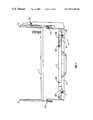
- FIG. 1is a perspective view of a therapeutic bed according to the invention
- FIG. 2is a another perspective view of the therapeutic bed, shown in another position of use;
- FIG. 3is a further perspective view of the bed with a patient support platform of the bed shown in an inverted prone patient supporting position;
- FIG. 4is an end elevational view of the bed
- FIG. 5is a perspective view of a frame of the therapeutic bed
- FIG. 6is a perspective view of a base portion of the bed frame with a patient support platform of the bed removed;
- FIG. 7is an elevational view of a frame of the bed
- FIG. 8is a plan view of the bed frame shown in FIG. 7 ;
- FIG. 9is a plan view similar to FIG. 8 showing hinged panels of the patient support platform in place on the bed frame;
- FIG. 10is a perspective view of the bed in use and supporting a patient in a supine position
- FIG. 11is a perspective view of the bed in use, supporting a patient in a prone position
- FIG. 12is a detail exploded sectional view of a side rail locking mechanism for the bed
- FIG. 13is a detail sectional elevational view of a side rail locking mechanism for the bed shown in another position of use;
- FIG. 14is a sectional elevational view of a panel locking mechanism on the patient support platform
- FIG. 15is an enlarged detail sectional view of portion of the locking mechanism of FIG. 14 ;
- FIG. 16is a view similar to FIG. 15 showing the locking mechanism in another position of use
- FIG. 17 ais a detail perspective view of patient retaining flaps of the bed
- FIG. 17 bis a circuit diagram for a rotational interlock incorporated in the flaps
- FIG. 17 cis a detail perspective view of a patient retaining strap and buckle for securing the flaps
- FIG. 18is an elevational view showing a tube guide at one end of the bed
- FIG. 19is a detail elevational view of a rotary encoder ring forming portion of a rotational control mechanism for the patient support platform of the bed;
- FIG. 20is a detail side elevational view of a rotary encoder forming portion of the bed.
- FIG. 21is a detail view showing portion of the rotary encoder ring.
- the bed 1comprises a ground engaging chassis 2 mounted on wheels 3 .
- a base frame 4is secured on the chassis 2 by pivot linkages 5 .
- Rams 6 housed within the base frame 4operate the pivot linkages 5 to raise and lower the base frame 4 on the chassis 2 .
- the rams 6may be operated to keep the base frame 4 level as it moves or may be operated to raise or lower one of the ends of the base frame 4 to tilt the base frame 4 about a transverse axis of the base frame 4 to move a patient support platform 7 carried on the base frame 4 into a Trendelenburg position.
- the patient support platform 7is rotatably mounted on the base frame 4 for rotation about a longitudinal rotational axis of the patient support platform 7 between a supine support position shown in FIG. 1 and a prone support position shown in FIG. 3 .
- the patient support platform 7has a pair of upright end rings 8 , 9 each of which sits on and rotatably engages an associated pair of spaced-apart rollers 10 ( FIG. 6 ) at each end of the base frame 4 .
- Side support bars 12 , 13extend between the end rings 8 , 9 .
- a central cross bar 14extends between the side support bars 12 , 13 .
- Hinged panels 16 , 17are hingedly connected to the cross bar 14 and can be opened when the bed 1 is in the prone position as illustrated in FIG. 3 for access to the back of a patient on the bed 1 . It will be noted that this construction gives good access to the patient with minimal obstruction.
- a slap shut mechanism 20( FIGS. 9 and 14 to 16 ) is mounted on each panel 16 , 17 for engagement with the support bars 12 , 13 to securely lock the panels 16 , 17 in the closed position.
- a spring loaded locking pin 22is slidably mounted within an elongate tubular housing 23 for movement between a retracted stored position ( FIG. 15 ) and an extended position ( FIG. 16 ) in which the locking pin 22 engages in an associated receiver slot 23 a in the support bars 12 , 13 .
- Sensorsdetect correct locking engagement of each locking pin 22 with its associated receiver slot 23 a and sends a signal to a rotational controller for the patient support platform 7 which prevents rotation of the patient support platform 7 unless both panels 16 , 17 are securely locked on the patient support platform 7 .
- a gravity pin 21is slidable under gravity in an associated tube 21 a on the housing 23 side wall for engagement with a complementary circumferential groove 24 in the locking bolt 22 when the patient support platform 7 is in the supine position to prevent opening of the panels 16 , 17 , the gravity pin 21 sliding out of engagement with the groove 24 when the patient support platform is in the prone position to allow opening of the panels 16 , 17 .
- a handle 98is provided at an inner end of the locking pin 22 for manual release of the locking pin 22 which can be retracted against spring 99 within the housing 23 .
- the panels 16 , 17are released for opening.
- a spring loaded catch 100 mounted on the locking pin 22engages a slot 101 in a side wall of the housing 23 to retain the locking pin 22 in the retracted position.
- the catch 100can be pressed into the housing 23 against spring 105 bias to release the locking pin 22 which is then urged outwardly by spring 99 into the outwardly extending engagement position shown in FIG. 16 for re-locking the panels 16 , 17 on the patient support platform 7 .
- Each side rail 25has a downwardly extending stanchion 26 at each end which is engagable with a complementary socket 27 (see FIG. 13 ) in one of the support bars 12 , 13 of the patient support platform 7 .
- a spring loaded locking pin 28 housed within the bar 12 , 13is engagable through an opening 24 in the side wall of the socket 27 with a locking slot 29 in the stanchion 26 .
- a handle 30 at an inner end of the locking pin 28is operable to slide the locking pin 28 in an associated housing 31 housed within the bar 12 , 13 for release of the stanchion 26 .
- a spring 31 a within the housing 31urges the locking pin 28 outwardly of the housing 31 into a stanchion engaging position.
- an associated gravity operated retaining pin 32is slidably mounted in a tubular casing 33 on the housing 31 such that when the patient support platform 7 is in the inverted prone position the pin 32 drops downwardly under gravity (in the direction of arrow A, FIG. 13 ) to prevent retraction of the pin 28 locking the rails 25 in position.
- a sensor 35is engagable with each pin 28 to determine the position of the pin 28 to register if the pin 28 is engaged or disengaged with the stanchion 26 .
- All of the sensors 35are connected in series and are connected to a rotational controller for a motor which rotates the patient support platform 7 such that the motor will not operate until all the sensors 35 indicate that the pins 28 are properly engaged with the stanchions 26 so that the rails 25 are securely attached to and locked in position on the patient support platform 7 .
- Each strap 43comprises a web 44 with either a buckle 45 ( FIG. 17 ) or associated clip 46 at a free end of the web 44 , the buckle 45 and clip 46 forming a quick release fastener.
- the web 44 when the buckle 45 is releasedis shortened by an elastic band 47 , which is sewn in a stretched position onto one side of the web 44 , to withdraw the buckle 45 from over a magnetically operated switch 48 mounted on the associated flap 41 on which the buckle 45 is mounted.
- the magnetic switch 48is mounted inside each flap 41 and immediately below the magnet in the tightened buckle 45 .
- a series circuit of the magnetic switch 48 and a resistor 49terminates in a connector 49 a which is accessible on an exterior of the flap 41 .
- the magnetically operated switch 48is operable to confirm that the buckles 45 and clips 46 are correctly joined and the patient is thus correctly secured on the patient support platform 7 .
- Each of the fastenersmust be correctly engaged before the patient support platform 7 can be rotated.
- a hand-held controller 85( FIG. 4 ) is mounted in a pocket 86 at the foot of the bed 1 .
- This controller 85has a contact for engagement with the connector 49 a to allow the controller 85 to check the buckle 45 is properly engaged (the switch 48 is closed) and determine the value of the resistance 48 to identify the flaps 40 , 41 being checked.
- Each of the flap pairs 40 , 41are checked in sequence starting at the foot of the bed and moving towards the head end of the bed.
- the patient support platform 7will not be released for rotation unless flap locking is confirmed in the correct sequence and the sequence is complete. This ensures all the flaps are checked together at the same time.
- the hand-held controller 85can be used to remotely send an operating signal to the rotation motor controller to rotate the patient support platform 7 .
- a nursecan move around the bed 1 as the patient support platform 7 rotates, controlling rotation with the controller 85 to ensure there are no problems with the patient or the patient care lines during rotation.
- Management means for patient care linessuch as tubes and sensor cables is provided on the bed.
- the management meanscomprises a central opening 50 ( FIG. 5 ) adjacent a longitudinal axis of the patient support platform 7 for supporting and through passage of the patient care lines.
- a care line holder 57( FIG. 4 ) is removably engagable within the opening 50 and has a number of spaced-apart circumferential slots 56 each for reception of a patient care line. Each slot 58 is closed by the side wall of the opening 50 .
- the patient care line management meanscomprises a guide body 51 ( FIGS. 1 and 18 ) mounted adjacent the longitudinal axis of the patient support platform 7 and slidable on associated rails 52 so that it drops beneath the head of the patient when the bed is in either the supine or the prone position.
- the guide 51has a number of slots 54 for reception of patient care lines.
- the slots 54may be of different sizes as shown to accommodate different lines.
- a spring loaded retaining finger 55mounted across the inlets of each slot 54 retains the patient care line within the slot 54 .
- the guide body 51is mounted on a rod 56 which is rotatably mounted on sliders 59 which slidably engage the rails 52 .
- the guide body 51can be rotated out of the way for better access to a patient's head if necessary. It will be appreciated that this patient care line management by leading the patient care lines axially outwardly at each end of the bed greatly facilitates handling of the patient care lines when moving the patient support platform between the supine and prone support positions. Also, the patient care lines are securely held to prevent inadvertent withdrawal from a patient.
- a drive for the patient support platformcan be of the type described in our Patent Specification No. WO97/22323 (the details of which are incorporated by reference), essentially comprising a belt drive between the patient support platform 7 and an associated electric motor on the base frame 4 at a foot end of the bed 1 .
- operation of the motoris controlled by a rotary opto encoder comprising a code disc 60 with three concentric tracks of slots 61 , 62 , 63 , see FIGS. 19 to 21 and a complementary position reader 64 .
- An outer angle track 61comprises slots at 1° intervals.
- An intermediate track 62has slots to provide index identification and an inner index track 63 has slots in line with the lock ring park position.
- the disc 60is attached to the patient support platform 7 and the associated position reader 64 is mounted on the base frame 4 .
- the position reader 64has a channel 64 a for reception and through passage of an outer portion of the disc 60 .
- Light emitters 65are mounted at one side of the channel 64 a and complementary light receivers 66 are mounted at the opposite side of the channel 64 a .
- the emitters 65 and receivers 66co-operate with the associated slots 61 , 62 , 63 in the disc 60 to indicate the orientation of the patient support platform 7 on the base frame 4 .
- Seven infra-red emitter/detector pairs 65 , 66are used in the optical system to decode the positional information.
- the outer track 61comprises 360 sets of slots 70 and spaces 71 .
- a slot 70occupies 0.5 degree of the circle, a slot 70 and space 71 together occupying 1 degree.
- the inner track 63consists of a number of narrow slots 74 , each corresponding to a locking position in which an associated locking bolt 75 ( FIG. 7 ) is engagable between the base frame 4 and the patient support platform 7 .
- the locking bolt 75is slidably mounted on the base frame 4 for engagement with and release from associated locking hobs on the ring 9 of the patient support platform 7 .
- the locking pin 75serves to mechanically anchor the patient support platform 7 on the base frame 4 and also operates an on/off switch for the rotation motor, preventing operation of the motor when the locking pin 75 is engaged with the patient support platform 7 .
- Each slot 74should be exactly in line with the centre of an associated locking hole 75 a on the patient support platform 7 , the narrowness of the slot 74 determining the accuracy of lock positioning.
- the intermediate track 62is used to assign a unique binary code to each locking position 1 .
- Each locking positionhas a set of holes 76 (varying in number from one to four holes 76 ).
- the unique pattern of holes 76 at each locking positionconveys locking angle information to the controller for controlling rotation of the patient support platform 7 .
- the binary pattern of the holesis shown in the table below.
- Holes 76(FIG. 21) LockPin position D C B A 1 0 0 0 1 2 0 0 1 0 3 0 0 1 1 4 0 1 0 0 5 0 1 0 1 6 0 1 1 0 7 0 1 1 1 8 1 0 0 0 9 1 0 0 1 10 1 0 1 0
- Seven infra-red emitter detector pairs 65 , 66are used in the optical system to decode the positional information.
- the emitter/detector pairs 65 , 66are positioned at A, B, C, D, I, X and Y as shown in FIG. 21 .
- the incremental angle and direction informationare read by X and Y. Every time a slot 70 passes over detector X, the angle is incremented or decremented by one. There are two spaced-apart detectors X and Y for the outer track 61 and the order in which the detectors X and Y see the emitter determines the direction. There are four spaced-part emitter/detector pairs A, B, C, D associated with the intermediate track 62 and these supply the pattern information to the controller to compute the locking angle information.
- emitter/detector pair Ithere is one emitter/detector pair I associated with the inner track 63 and this supplies the locking position information.
- the patient support platform 7rotates the spaces between the slots interrupt infra-red beams passing between emitters 65 and receivers 66 on a support 67 on the base frame 4 .
- Information from the infra-red detectorsis processed by an optical processing controller to provide the angle of the patient support platform 7 which is indicated on a display screen 80 ( FIG. 4 ) at a foot end of the bed 1 .
- the pivot linkages 5have pivot arms 90 , 91 having inner ends which pivotally engage the base frame 4 by pivot pins 92 , 93 .
- an outer end of each pivot arm 90pivotally engages the chassis 2 by a pivot pin 94
- the outer end of each pivot arm 91pivotally engages the chassis 2 by pivot pins 95 which are also longitudinally slidable in elongate slots 96 on the chassis 2 .
- the rams 6are operable to rotate the pivot pins 92 , 93 on the base frame 4 for operation of the pivot linkages 5 .
- sensors associated with the side rails 25 and the panels 16 , 17 on the patient support platform 7are connected to the drive controller for the patient support platform 7 such that the patient support platform cannot be rotated unless all the locks are correctly engaged. Further the sensors for the straps of the patient retaining flaps 40 , 41 also need to indicate correct engagement before the patient support platform 7 can be rotated. It will also be appreciated that the delivery of the patient care lines such as tubes and other cables and conduits axially outwardly at each end of the patient support platform greatly facilitates management of the patient care lines during movement of the patient support platform between the supine and prone positions.
- the patient support platformmay be oscillated on the base frame or may be locked in a number of fixed orientations on the base frame.
- the inventionprovides a patient care line guide system for a hospital bed for neatly guiding patient care lines off each end of the bed.
Landscapes
- Health & Medical Sciences (AREA)
- Nursing (AREA)
- Life Sciences & Earth Sciences (AREA)
- Animal Behavior & Ethology (AREA)
- General Health & Medical Sciences (AREA)
- Public Health (AREA)
- Veterinary Medicine (AREA)
- Invalid Beds And Related Equipment (AREA)
Abstract
Description
- said retaining means being operatively connected to the drive means to regulate rotation of the patient support platform in response to correct engagement of the retaining means.
- each pair of support elements comprising associated support elements mounted on opposite sides of the patient support platform and having a fastener to secure the support elements together to retain a patient on the patient support platform,
- sensing means associated with each fastener to sense correct engagement of the fastener,
- said sensing means being connected to a controller for controlling operation of the drive means.
- one fastener part being mounted on each of the pair of support elements,
- the first fastener part being normally biased out of engagement with the second fastener part,
- the first fastener part co-operating with the sensor when in an engaged position to indicate that the fastener parts are engaged.
- locking means to secure the rail on the patient support platform,
- rail sensing means to sense interlocking engagement of the rail with the patient support platform,
- said rail sensing means being operatively connected to the controller for the drive means such that the drive means will only operate if the rail is correctly engaged with the patient support platform.
- each panel having panel locking means to secure the panel in a closed position on the patient support platform,
- panel sensing means being provided to sense locking engagement of the panel with the patient support platform,
- said panel sensing means being operatively connected to the controller for the drive means such that the drive means will only operate if the panel is locked in a closed position on the patient support platform.
- the ring having a first series of slots spaced at 1° intervals about the ring,
- the ring having a number of sets of location slots spaced-apart about the ring, each set of location slots giving an indication of a particular orientation of the patient support platform relative to the base frame,
- and a complementary position reader associated with the disc, the position reader being mounted on the base frame and having complementary light emitter and receiver pairs supported at opposite sides of the disc for cooperation with the slots in the disc to determine the orientation of the patient support platform on the base frame.
| Holes 76 (FIG. 21) | |||
| LockPin position | D | B | A | ||
| 1 | 0 | 0 | 0 | 1 |
| 2 | 0 | 0 | 1 | 0 |
| 3 | 0 | 0 | 1 | 1 |
| 4 | 0 | 1 | 0 | 0 |
| 5 | 0 | 1 | 0 | 1 |
| 6 | 0 | 1 | 1 | 0 |
| 7 | 0 | 1 | 1 | 1 |
| 8 | 1 | 0 | 0 | 0 |
| 9 | 1 | 0 | 0 | 1 |
| 10 | 1 | 0 | 1 | 0 |
Claims (55)
Applications Claiming Priority (3)
| Application Number | Priority Date | Filing Date | Title |
|---|---|---|---|
| IE950950 | 1995-12-18 | ||
| IE980415 | 1998-06-03 | ||
| PCT/IE1999/000049WO1999062454A1 (en) | 1998-06-03 | 1999-06-03 | A therapeutic bed |
Publications (1)
| Publication Number | Publication Date |
|---|---|
| US6874181B1true US6874181B1 (en) | 2005-04-05 |
Family
ID=34379542
Family Applications (1)
| Application Number | Title | Priority Date | Filing Date |
|---|---|---|---|
| US09/701,739Expired - LifetimeUS6874181B1 (en) | 1995-12-18 | 1999-06-03 | Therapeutic bed |
Country Status (1)
| Country | Link |
|---|---|
| US (1) | US6874181B1 (en) |
Cited By (57)
| Publication number | Priority date | Publication date | Assignee | Title |
|---|---|---|---|---|
| US20040171974A1 (en)* | 2002-12-16 | 2004-09-02 | Cert Health Sciences, Llc | Method and apparatus for therapeutic treatment of back pain |
| US20060037141A1 (en)* | 2001-03-29 | 2006-02-23 | Krywiczanin Wladyslaw H | Data and power interface for therapeutic bed |
| US20060075553A1 (en)* | 2004-06-14 | 2006-04-13 | Patient Safety Transport Systems Gp, Llc | Patient transfer system |
| US20060117482A1 (en)* | 2004-12-07 | 2006-06-08 | Branson Gregory W | Touch screen control for lateral rotation of a hospital bed mattress |
| US20070113336A1 (en)* | 2005-11-19 | 2007-05-24 | Patient Safety Transport Systems Gp, Llc | Back surgery platform |
| US20070181751A1 (en)* | 2006-02-08 | 2007-08-09 | Newkirk David C | Line management device |
| US20080202527A1 (en)* | 2007-01-23 | 2008-08-28 | Kci Licensing, Inc. | Providing automated or manual guidance on dynamic patient positioning based on measured variables for ventilation control |
| US20090049612A1 (en)* | 2007-08-20 | 2009-02-26 | Hornbach David W | Laterally rotating patient support apparatus |
| US20090307844A1 (en)* | 2008-06-13 | 2009-12-17 | Hornbach David W | Transport Apparatus |
| WO2009156848A1 (en)* | 2008-06-27 | 2009-12-30 | Flotteor Sarl | Bedding device for improving sleep |
| US20100275371A1 (en)* | 2009-04-30 | 2010-11-04 | Turner Jonathan D | Transfer assist apparatus |
| US7992238B2 (en)* | 2007-09-13 | 2011-08-09 | Thomas Hejkal | Rotatable surgery table |
| US20120006334A1 (en)* | 2010-07-09 | 2012-01-12 | Nelson Cayabyab | Rotating sex machine |
| US20120246831A1 (en)* | 2009-10-06 | 2012-10-04 | Flotteor | Hospital bed |
| US9072646B2 (en) | 2010-12-14 | 2015-07-07 | Allen Medical Systems, Inc. | Lateral surgical platform with rotation |
| US9498397B2 (en) | 2012-04-16 | 2016-11-22 | Allen Medical Systems, Inc. | Dual column surgical support system |
| US9655793B2 (en) | 2015-04-09 | 2017-05-23 | Allen Medical Systems, Inc. | Brake release mechanism for surgical table |
| CN107456334A (en)* | 2017-09-19 | 2017-12-12 | 河南城建学院 | A kind of rehabilitation bed that back of the body counteracting bedsores function is kowtowed with automatic turn-over body |
| US9901503B2 (en) | 2008-03-13 | 2018-02-27 | Optimedica Corporation | Mobile patient bed |
| US10363189B2 (en) | 2015-10-23 | 2019-07-30 | Allen Medical Systems, Inc. | Surgical patient support for accommodating lateral-to-prone patient positioning |
| US10426684B2 (en) | 2015-06-11 | 2019-10-01 | Allen Medical Systems, Inc. | Person support apparatuses including person repositioning assemblies |
| US10492973B2 (en) | 2015-01-05 | 2019-12-03 | Allen Medical Systems, Inc. | Dual modality prone spine patient support apparatuses |
| US10543142B2 (en)* | 2017-08-10 | 2020-01-28 | Warsaw Orthopedic, Inc. | Surgical frame including torso-sling and method for use thereof |
| US10548793B2 (en) | 2016-06-14 | 2020-02-04 | Allen Medical Systems, Inc. | Pinless loading for spine table |
| US10561559B2 (en) | 2015-10-23 | 2020-02-18 | Allen Medical Systems, Inc. | Surgical patient support system and method for lateral-to-prone support of a patient during spine surgery |
| US10751240B2 (en) | 2015-08-17 | 2020-08-25 | Warsaw Orthopedic, Inc. | Surgical frame and method for use thereof facilitating articulatable support for a patient during surgery |
| US10857054B2 (en) | 2015-11-13 | 2020-12-08 | Allen Medical Systems, Inc. | Person support apparatuses for subject repositioning |
| US10874570B2 (en) | 2017-06-30 | 2020-12-29 | Warsaw Orthopedic, Inc. | Surgical frame and method for use thereof facilitating patient transfer |
| US10881570B2 (en) | 2019-04-26 | 2021-01-05 | Warsaw Orthopedic, Inc | Reconfigurable pelvic support for a surgical frame and method for use thereof |
| US10888484B2 (en) | 2019-04-26 | 2021-01-12 | Warsaw Orthopedic, Inc | Reconfigurable pelvic support for surgical frame and method for use thereof |
| US10893996B2 (en) | 2018-08-22 | 2021-01-19 | Warsaw Orthopedic, Inc. | Surgical frame having translating lower beam and moveable linkage or surgical equipment attached thereto and method for use thereof |
| US10898401B2 (en) | 2018-08-22 | 2021-01-26 | Warsaw Orthopedic, Inc. | Reconfigurable surgical frame and method for use |
| US10900448B2 (en) | 2017-03-10 | 2021-01-26 | Warsaw Orthopedic, Inc. | Reconfigurable surgical frame and method for use thereof |
| CN112402167A (en)* | 2020-12-02 | 2021-02-26 | 郑丹阳 | Restraint device for neurology department treatment and using method |
| US10940072B2 (en) | 2016-10-28 | 2021-03-09 | Warsaw Orthopedic, Inc. | Surgical table and method for use thereof |
| US10966892B2 (en) | 2015-08-17 | 2021-04-06 | Warsaw Orthopedic, Inc. | Surgical frame facilitating articulatable support for a patient during surgery |
| US11020304B2 (en) | 2017-08-08 | 2021-06-01 | Warsaw Orthopedic, Inc. | Surgical frame including main beam for facilitating patient access |
| CN113543571A (en)* | 2019-07-02 | 2021-10-22 | 川湖科技股份有限公司 | Wire management assembly |
| US11202731B2 (en) | 2018-02-28 | 2021-12-21 | Allen Medical Systems, Inc. | Surgical patient support and methods thereof |
| US11213448B2 (en) | 2017-07-31 | 2022-01-04 | Allen Medical Systems, Inc. | Rotation lockout for surgical support |
| US11234886B2 (en) | 2019-09-25 | 2022-02-01 | Warsaw Orthopedic, Inc. | Reconfigurable upper leg support for a surgical frame |
| US11304867B2 (en) | 2020-04-22 | 2022-04-19 | Warsaw Orthopedic, Inc. | Lift and method for use of a lift for positioning a patient relative to a surgical frame |
| US11389362B2 (en) | 2017-06-30 | 2022-07-19 | Warsaw Orthopedic, Inc. | Surgical frame having translating lower beam and method for use thereof |
| US11471354B2 (en) | 2018-08-30 | 2022-10-18 | Allen Medical Systems, Inc. | Patient support with selectable pivot |
| US11510594B2 (en)* | 2017-12-07 | 2022-11-29 | Paramount Bed Co., Ltd. | Posture determination apparatus |
| US11696863B2 (en) | 2018-08-21 | 2023-07-11 | Warsaw Orthopedic, Inc. | Surgical frame having translating lower beam and moveable linkage or surgical equipment attached thereto and method for use thereof |
| US11813217B2 (en) | 2020-04-22 | 2023-11-14 | Warsaw Orthopedic, Inc | Lift and method for use of a lift for positioning a patient relative to a surgical frame |
| US11925586B2 (en) | 2022-03-25 | 2024-03-12 | Mazor Robotics Ltd. | Surgical platform and trolley assembly |
| US12042440B1 (en) | 2021-04-16 | 2024-07-23 | Turn Medical, LLC | Stowable patient supports |
| US12121479B1 (en) | 2021-04-16 | 2024-10-22 | Turn Medical, LLC | Strap and release system |
| US12150902B2 (en) | 2022-05-10 | 2024-11-26 | Warsaw Orthopedic, Inc. | Surgical table |
| US12207946B2 (en) | 2022-05-10 | 2025-01-28 | Warsaw Orthopedic, Inc. | Surgical platform system |
| US12213905B2 (en) | 2022-05-10 | 2025-02-04 | Warsaw Orthopedic, Inc. | Surgical platform system |
| US12226356B1 (en) | 2021-04-16 | 2025-02-18 | Turn Medical, LLC | Adjustable posterior head support |
| US12239584B2 (en) | 2022-06-22 | 2025-03-04 | Warsaw Orthopedic, Inc. | Interface moveably interconnecting surgical table and gantry |
| US12396909B2 (en) | 2022-08-29 | 2025-08-26 | Warsaw Orthopedic, Inc. | Surgical platform system |
| US12403057B1 (en) | 2021-04-16 | 2025-09-02 | Turn Medical, LLC | Proning face pack |
Citations (34)
| Publication number | Priority date | Publication date | Assignee | Title |
|---|---|---|---|---|
| US1644043A (en) | 1923-02-09 | 1927-10-04 | Tiedemann Paul | Adjustable cot |
| US1667982A (en) | 1925-06-04 | 1928-05-01 | Pearson Royal Washington | Revolving bed |
| US1740906A (en) | 1925-06-17 | 1929-12-24 | Rothauszky Simon | Adjustable sectional bed |
| US2103693A (en) | 1934-02-12 | 1937-12-28 | Pohl Ernst | Radiographic couch |
| US2239821A (en) | 1939-08-01 | 1941-04-29 | Medical Engineering Company | Fracture frame |
| US2534471A (en) | 1946-11-04 | 1950-12-19 | Ludwig M Norheim | Revolving bed |
| US2613371A (en) | 1950-06-16 | 1952-10-14 | Jr Kenneth S Keyes | Turnover bed |
| US2690177A (en)* | 1951-05-25 | 1954-09-28 | Clifford W Hogan | Traction maintaining turning frame |
| FR1362417A (en) | 1962-09-05 | 1964-06-05 | Nursing and turning bed, tiltable | |
| US3286707A (en) | 1963-10-28 | 1966-11-22 | Forest M Shafer | Rotating device with inflatable means for securing a human therein |
| US3302218A (en) | 1965-05-28 | 1967-02-07 | Stryker Corp | Turning frame |
| US3434165A (en) | 1967-07-03 | 1969-03-25 | Vickers Ltd | Hospital bed |
| US3783863A (en) | 1971-02-01 | 1974-01-08 | W Kliever | Method and apparatus for immobilizing a patient and conducting an x-ray examination |
| US3827089A (en) | 1971-09-16 | 1974-08-06 | W Grow | Turnover bed assembly |
| US3832742A (en) | 1972-06-07 | 1974-09-03 | Stryker Corp | End support for anterior bed frame |
| GB1516488A (en) | 1976-03-04 | 1978-07-05 | Keane F | Hospital beds |
| US4244358A (en) | 1979-09-10 | 1981-01-13 | Noel Pyers | Rollover bed having pallet with flex points and constant traction maintaining apparatus |
| US4357722A (en) | 1979-04-05 | 1982-11-09 | Egerton Hospital Equipment Limited | Bed with adjustably tensionable patient supporting net |
| US4827541A (en) | 1987-12-15 | 1989-05-09 | Vollman Kathleen M | Prone patient positioner |
| US4841585A (en) | 1987-03-12 | 1989-06-27 | Kabushiki Kaisha Toshiba | Swingable and slidable bed apparatus |
| US4868937A (en) | 1986-05-02 | 1989-09-26 | Ethos Medical Research Limited | Therapeutic bed |
| US4939801A (en) | 1988-12-22 | 1990-07-10 | Schaal Gary A | Patient transporting and turning gurney |
| US4947496A (en)* | 1987-11-02 | 1990-08-14 | Ethos Medical Research Limited | Therapeutic bed |
| US4987622A (en) | 1989-05-22 | 1991-01-29 | Shockey Winfred S | Self-operated stand up support apparatus |
| US5131106A (en)* | 1990-08-30 | 1992-07-21 | Jackson Roger P | Spinal surgery table |
| US5131105A (en) | 1990-11-21 | 1992-07-21 | Diasonics, Inc. | Patient support table |
| US5152024A (en)* | 1985-04-17 | 1992-10-06 | Thomas J. Ring | Therapeutic table-with time based tilt motor controller |
| US5274862A (en) | 1992-05-18 | 1994-01-04 | Palmer Jr John M | Patient turning device and method for lateral traveling transfer system |
| US5334186A (en)* | 1992-11-09 | 1994-08-02 | Alexander Stephen M | Medical tubing and implement organizer |
| DE4429062A1 (en) | 1994-08-17 | 1996-02-22 | Manfred Wienaeber | Swivel bed with height=adjustable frame |
| WO1996027356A1 (en) | 1995-03-08 | 1996-09-12 | Alliance Investments Limited | A therapeutic bed |
| WO1997022323A1 (en) | 1995-12-18 | 1997-06-26 | Alliance Investments Limited | A therapeutic device |
| US6282736B1 (en)* | 1997-08-08 | 2001-09-04 | Hill-Rom Services, Inc. | Proning bed |
| US6526610B1 (en)* | 1998-06-26 | 2003-03-04 | Hill-Rom Services, Inc. | Proning bed |
- 1999
- 1999-06-03USUS09/701,739patent/US6874181B1/ennot_activeExpired - Lifetime
Patent Citations (37)
| Publication number | Priority date | Publication date | Assignee | Title |
|---|---|---|---|---|
| US1644043A (en) | 1923-02-09 | 1927-10-04 | Tiedemann Paul | Adjustable cot |
| US1667982A (en) | 1925-06-04 | 1928-05-01 | Pearson Royal Washington | Revolving bed |
| US1740906A (en) | 1925-06-17 | 1929-12-24 | Rothauszky Simon | Adjustable sectional bed |
| US2103693A (en) | 1934-02-12 | 1937-12-28 | Pohl Ernst | Radiographic couch |
| US2239821A (en) | 1939-08-01 | 1941-04-29 | Medical Engineering Company | Fracture frame |
| US2534471A (en) | 1946-11-04 | 1950-12-19 | Ludwig M Norheim | Revolving bed |
| US2613371A (en) | 1950-06-16 | 1952-10-14 | Jr Kenneth S Keyes | Turnover bed |
| US2690177A (en)* | 1951-05-25 | 1954-09-28 | Clifford W Hogan | Traction maintaining turning frame |
| FR1362417A (en) | 1962-09-05 | 1964-06-05 | Nursing and turning bed, tiltable | |
| US3238539A (en)* | 1962-09-05 | 1966-03-08 | Koch Albert | Rotatable beds for invalids |
| US3286707A (en) | 1963-10-28 | 1966-11-22 | Forest M Shafer | Rotating device with inflatable means for securing a human therein |
| US3302218A (en) | 1965-05-28 | 1967-02-07 | Stryker Corp | Turning frame |
| US3434165A (en) | 1967-07-03 | 1969-03-25 | Vickers Ltd | Hospital bed |
| US3434165B1 (en) | 1967-07-03 | 1983-12-06 | ||
| US3783863A (en) | 1971-02-01 | 1974-01-08 | W Kliever | Method and apparatus for immobilizing a patient and conducting an x-ray examination |
| US3827089A (en) | 1971-09-16 | 1974-08-06 | W Grow | Turnover bed assembly |
| US3832742A (en) | 1972-06-07 | 1974-09-03 | Stryker Corp | End support for anterior bed frame |
| GB1516488A (en) | 1976-03-04 | 1978-07-05 | Keane F | Hospital beds |
| US4357722A (en) | 1979-04-05 | 1982-11-09 | Egerton Hospital Equipment Limited | Bed with adjustably tensionable patient supporting net |
| US4244358A (en) | 1979-09-10 | 1981-01-13 | Noel Pyers | Rollover bed having pallet with flex points and constant traction maintaining apparatus |
| US5152024A (en)* | 1985-04-17 | 1992-10-06 | Thomas J. Ring | Therapeutic table-with time based tilt motor controller |
| US4868937A (en) | 1986-05-02 | 1989-09-26 | Ethos Medical Research Limited | Therapeutic bed |
| US4841585A (en) | 1987-03-12 | 1989-06-27 | Kabushiki Kaisha Toshiba | Swingable and slidable bed apparatus |
| US4947496A (en)* | 1987-11-02 | 1990-08-14 | Ethos Medical Research Limited | Therapeutic bed |
| US4827541A (en) | 1987-12-15 | 1989-05-09 | Vollman Kathleen M | Prone patient positioner |
| US4939801A (en) | 1988-12-22 | 1990-07-10 | Schaal Gary A | Patient transporting and turning gurney |
| US4987622A (en) | 1989-05-22 | 1991-01-29 | Shockey Winfred S | Self-operated stand up support apparatus |
| US5131106A (en)* | 1990-08-30 | 1992-07-21 | Jackson Roger P | Spinal surgery table |
| US5131105A (en) | 1990-11-21 | 1992-07-21 | Diasonics, Inc. | Patient support table |
| US5274862A (en) | 1992-05-18 | 1994-01-04 | Palmer Jr John M | Patient turning device and method for lateral traveling transfer system |
| US5334186A (en)* | 1992-11-09 | 1994-08-02 | Alexander Stephen M | Medical tubing and implement organizer |
| DE4429062A1 (en) | 1994-08-17 | 1996-02-22 | Manfred Wienaeber | Swivel bed with height=adjustable frame |
| WO1996027356A1 (en) | 1995-03-08 | 1996-09-12 | Alliance Investments Limited | A therapeutic bed |
| WO1997022323A1 (en) | 1995-12-18 | 1997-06-26 | Alliance Investments Limited | A therapeutic device |
| US6282736B1 (en)* | 1997-08-08 | 2001-09-04 | Hill-Rom Services, Inc. | Proning bed |
| US6499160B2 (en)* | 1997-08-08 | 2002-12-31 | Hill-Rom Services, Inc. | Hospital bed |
| US6526610B1 (en)* | 1998-06-26 | 2003-03-04 | Hill-Rom Services, Inc. | Proning bed |
Cited By (106)
| Publication number | Priority date | Publication date | Assignee | Title |
|---|---|---|---|---|
| US20060037141A1 (en)* | 2001-03-29 | 2006-02-23 | Krywiczanin Wladyslaw H | Data and power interface for therapeutic bed |
| US7219379B2 (en)* | 2001-03-29 | 2007-05-22 | Kci Licensing, Inc. | Therapeutic bed |
| US20070198061A1 (en)* | 2002-12-16 | 2007-08-23 | Cert Health Sciences, Llc | Method and apparatus for therapeutic treatment of back pain |
| US7201729B2 (en) | 2002-12-16 | 2007-04-10 | Cert Health Sciences, Llc | Method and apparatus for therapeutic treatment of back pain |
| US20040171974A1 (en)* | 2002-12-16 | 2004-09-02 | Cert Health Sciences, Llc | Method and apparatus for therapeutic treatment of back pain |
| US7540877B2 (en) | 2002-12-16 | 2009-06-02 | Emsky Timothy R | Method and apparatus for therapeutic treatment of back pain |
| US20060075553A1 (en)* | 2004-06-14 | 2006-04-13 | Patient Safety Transport Systems Gp, Llc | Patient transfer system |
| US7197778B2 (en) | 2004-06-14 | 2007-04-03 | Patient Safety Transport Systems Gp, Llc | Patient transfer system |
| US20060117482A1 (en)* | 2004-12-07 | 2006-06-08 | Branson Gregory W | Touch screen control for lateral rotation of a hospital bed mattress |
| US7290302B2 (en) | 2005-11-19 | 2007-11-06 | Patient Safety Transport Systems Gp, Llc | Back surgery platform |
| US20070113336A1 (en)* | 2005-11-19 | 2007-05-24 | Patient Safety Transport Systems Gp, Llc | Back surgery platform |
| US20070181751A1 (en)* | 2006-02-08 | 2007-08-09 | Newkirk David C | Line management device |
| US7766289B2 (en) | 2006-02-08 | 2010-08-03 | Hill-Rom Services, Inc. | Line management device |
| US20100263123A1 (en)* | 2006-02-08 | 2010-10-21 | Newkirk David C | Line management device for a hospital bed |
| US8370977B2 (en) | 2006-02-08 | 2013-02-12 | Hill-Rom Services, Inc. | Line management device for a hospital bed |
| US8202226B2 (en) | 2007-01-23 | 2012-06-19 | Kci Licensing, Inc. | Providing automated or manual guidance on dynamic patient positioning based on measured variables for ventilation control |
| US20080202527A1 (en)* | 2007-01-23 | 2008-08-28 | Kci Licensing, Inc. | Providing automated or manual guidance on dynamic patient positioning based on measured variables for ventilation control |
| US20090049612A1 (en)* | 2007-08-20 | 2009-02-26 | Hornbach David W | Laterally rotating patient support apparatus |
| US7992239B2 (en) | 2007-08-20 | 2011-08-09 | Hill-Rom Services, Inc. | Laterally rotating patient support apparatus |
| US7992238B2 (en)* | 2007-09-13 | 2011-08-09 | Thomas Hejkal | Rotatable surgery table |
| US9901503B2 (en) | 2008-03-13 | 2018-02-27 | Optimedica Corporation | Mobile patient bed |
| US10426685B2 (en) | 2008-03-13 | 2019-10-01 | Optimedica Corporation | Mobile patient bed |
| US20090307844A1 (en)* | 2008-06-13 | 2009-12-17 | Hornbach David W | Transport Apparatus |
| US8590074B2 (en) | 2008-06-13 | 2013-11-26 | Hill-Rom Services, Inc. | Transport apparatus |
| WO2009156848A1 (en)* | 2008-06-27 | 2009-12-30 | Flotteor Sarl | Bedding device for improving sleep |
| US20100275371A1 (en)* | 2009-04-30 | 2010-11-04 | Turner Jonathan D | Transfer assist apparatus |
| US9693915B2 (en) | 2009-04-30 | 2017-07-04 | Hill-Rom Services, Inc. | Transfer assist apparatus |
| US20120246831A1 (en)* | 2009-10-06 | 2012-10-04 | Flotteor | Hospital bed |
| US20120006334A1 (en)* | 2010-07-09 | 2012-01-12 | Nelson Cayabyab | Rotating sex machine |
| US9072646B2 (en) | 2010-12-14 | 2015-07-07 | Allen Medical Systems, Inc. | Lateral surgical platform with rotation |
| US11938065B2 (en)* | 2012-04-16 | 2024-03-26 | Allen Medical Systems, Inc. | Table top to bracket coupling apparatus for spine surgery table |
| US9968503B2 (en) | 2012-04-16 | 2018-05-15 | Allen Medical Systems, Inc. | Dual column surgical table having a single-handle unlock for table rotation |
| US11452657B2 (en) | 2012-04-16 | 2022-09-27 | Allen Medical Systems, Inc. | Dual column surgical table having a single-handle unlock for table rotation |
| US9498397B2 (en) | 2012-04-16 | 2016-11-22 | Allen Medical Systems, Inc. | Dual column surgical support system |
| US12186242B2 (en) | 2012-04-16 | 2025-01-07 | Allen Medical Systems, Inc. | Dual column surgical table having a single-handle unlock for table rotation |
| US20210220202A1 (en)* | 2012-04-16 | 2021-07-22 | Allen Medical Systems, Inc. | Table top to bracket coupling apparatus for spine surgery table |
| US10993864B2 (en) | 2012-04-16 | 2021-05-04 | Allen Medical Systems, Inc. | Bracket attachment apparatus for dual column surgical table |
| US10492973B2 (en) | 2015-01-05 | 2019-12-03 | Allen Medical Systems, Inc. | Dual modality prone spine patient support apparatuses |
| US9655793B2 (en) | 2015-04-09 | 2017-05-23 | Allen Medical Systems, Inc. | Brake release mechanism for surgical table |
| US10426684B2 (en) | 2015-06-11 | 2019-10-01 | Allen Medical Systems, Inc. | Person support apparatuses including person repositioning assemblies |
| US11957626B2 (en) | 2015-08-17 | 2024-04-16 | Warsaw Orthopedic, Inc. | Surgical frame and method for use thereof facilitating articulatable support for a patient during surgery |
| US10966892B2 (en) | 2015-08-17 | 2021-04-06 | Warsaw Orthopedic, Inc. | Surgical frame facilitating articulatable support for a patient during surgery |
| US10751240B2 (en) | 2015-08-17 | 2020-08-25 | Warsaw Orthopedic, Inc. | Surgical frame and method for use thereof facilitating articulatable support for a patient during surgery |
| US11612533B2 (en) | 2015-08-17 | 2023-03-28 | Warsaw Orthopedic, Inc. | Surgical frame facilitating articulatable support for a patient during surgery |
| US12403055B2 (en) | 2015-10-23 | 2025-09-02 | Allen Medical Systems, Inc. | Surgical patient support for lateral-to-prone patient positioning |
| US11096853B2 (en) | 2015-10-23 | 2021-08-24 | Allen Medical Systems, Inc. | Surgical patient support for accommodating lateral-to-prone patient positioning |
| US10561559B2 (en) | 2015-10-23 | 2020-02-18 | Allen Medical Systems, Inc. | Surgical patient support system and method for lateral-to-prone support of a patient during spine surgery |
| US10792207B2 (en) | 2015-10-23 | 2020-10-06 | Allen Medical Systems, Inc. | Lateral-to-prone spine surgery table |
| US10363189B2 (en) | 2015-10-23 | 2019-07-30 | Allen Medical Systems, Inc. | Surgical patient support for accommodating lateral-to-prone patient positioning |
| US11642269B2 (en) | 2015-11-13 | 2023-05-09 | Allen Medical Systems, Inc. | Person support apparatuses for subject repositioning |
| US12433811B2 (en) | 2015-11-13 | 2025-10-07 | Allen Medical Systems, Inc. | Person support apparatuses for subject repositioning |
| US10857054B2 (en) | 2015-11-13 | 2020-12-08 | Allen Medical Systems, Inc. | Person support apparatuses for subject repositioning |
| US10548793B2 (en) | 2016-06-14 | 2020-02-04 | Allen Medical Systems, Inc. | Pinless loading for spine table |
| US10940072B2 (en) | 2016-10-28 | 2021-03-09 | Warsaw Orthopedic, Inc. | Surgical table and method for use thereof |
| US11857467B2 (en) | 2016-10-28 | 2024-01-02 | Warsaw Orthopedic, Inc. | Surgical table and method for use thereof |
| US10900448B2 (en) | 2017-03-10 | 2021-01-26 | Warsaw Orthopedic, Inc. | Reconfigurable surgical frame and method for use thereof |
| US11389362B2 (en) | 2017-06-30 | 2022-07-19 | Warsaw Orthopedic, Inc. | Surgical frame having translating lower beam and method for use thereof |
| US11052008B2 (en) | 2017-06-30 | 2021-07-06 | Warsaw Orthopedic, Inc. | Surgical frame and method for use thereof facilitating patient transfer |
| US10874570B2 (en) | 2017-06-30 | 2020-12-29 | Warsaw Orthopedic, Inc. | Surgical frame and method for use thereof facilitating patient transfer |
| US12186243B2 (en) | 2017-06-30 | 2025-01-07 | Warsaw Orthopedic, Inc. | Surgical frame having translating lower beam and method for use thereof |
| US12029689B2 (en) | 2017-07-31 | 2024-07-09 | Allen Medical Systems, Inc. | Controls for surgical support apparatus |
| US11554068B2 (en) | 2017-07-31 | 2023-01-17 | Allen Medical Systems, Inc. | Rotation lockout for surgical support |
| US11752055B2 (en) | 2017-07-31 | 2023-09-12 | Allen Medical Systems, Inc. | Rotation lockout for surgical support |
| US11213448B2 (en) | 2017-07-31 | 2022-01-04 | Allen Medical Systems, Inc. | Rotation lockout for surgical support |
| US11819461B2 (en) | 2017-08-08 | 2023-11-21 | Warsaw Orthopedic, Inc. | Surgical frame including main beam for facilitating patient access |
| US11020304B2 (en) | 2017-08-08 | 2021-06-01 | Warsaw Orthopedic, Inc. | Surgical frame including main beam for facilitating patient access |
| US12427075B2 (en) | 2017-08-08 | 2025-09-30 | Warsaw Orthopedic, Inc. | Surgical frame including main beam for facilitating patient access |
| US10849809B2 (en) | 2017-08-10 | 2020-12-01 | Warsaw Orthopedic, Inc. | Surgical frame including torso-sling and method for use thereof |
| US10722413B2 (en) | 2017-08-10 | 2020-07-28 | Warsaw Orthopedic, Inc. | Surgical frame including torso-sling and method for use thereof |
| US10543142B2 (en)* | 2017-08-10 | 2020-01-28 | Warsaw Orthopedic, Inc. | Surgical frame including torso-sling and method for use thereof |
| CN107456334B (en)* | 2017-09-19 | 2023-02-03 | 河南城建学院 | A rehabilitation bed with the function of automatically turning over and knocking on the back to prevent decubitus |
| CN107456334A (en)* | 2017-09-19 | 2017-12-12 | 河南城建学院 | A kind of rehabilitation bed that back of the body counteracting bedsores function is kowtowed with automatic turn-over body |
| US11510594B2 (en)* | 2017-12-07 | 2022-11-29 | Paramount Bed Co., Ltd. | Posture determination apparatus |
| US20230037703A1 (en)* | 2017-12-07 | 2023-02-09 | Paramount Bed Co., Ltd. | Posture determination apparatus |
| US11813055B2 (en)* | 2017-12-07 | 2023-11-14 | Paramount Bed Co., Ltd. | Posture determination apparatus |
| CN116059051A (en)* | 2017-12-07 | 2023-05-05 | 八乐梦床业株式会社 | Bed system |
| CN116059051B (en)* | 2017-12-07 | 2025-07-15 | 八乐梦床业株式会社 | Bed System |
| US11202731B2 (en) | 2018-02-28 | 2021-12-21 | Allen Medical Systems, Inc. | Surgical patient support and methods thereof |
| US12220359B2 (en) | 2018-02-28 | 2025-02-11 | Allen Medical Systems, Inc. | Surgical patient support and methods thereof |
| US11696863B2 (en) | 2018-08-21 | 2023-07-11 | Warsaw Orthopedic, Inc. | Surgical frame having translating lower beam and moveable linkage or surgical equipment attached thereto and method for use thereof |
| US10893996B2 (en) | 2018-08-22 | 2021-01-19 | Warsaw Orthopedic, Inc. | Surgical frame having translating lower beam and moveable linkage or surgical equipment attached thereto and method for use thereof |
| US10898401B2 (en) | 2018-08-22 | 2021-01-26 | Warsaw Orthopedic, Inc. | Reconfigurable surgical frame and method for use |
| US11624342B2 (en) | 2018-08-22 | 2023-04-11 | Warsaw Orthopedic, Inc. | Reconfigurable surgical frame and method for use thereof |
| US12123381B2 (en) | 2018-08-22 | 2024-10-22 | Warsaw Orthopedic, Inc. | Reconfigurable surgical frame and method for use thereof |
| US11471354B2 (en) | 2018-08-30 | 2022-10-18 | Allen Medical Systems, Inc. | Patient support with selectable pivot |
| US10881570B2 (en) | 2019-04-26 | 2021-01-05 | Warsaw Orthopedic, Inc | Reconfigurable pelvic support for a surgical frame and method for use thereof |
| US10888484B2 (en) | 2019-04-26 | 2021-01-12 | Warsaw Orthopedic, Inc | Reconfigurable pelvic support for surgical frame and method for use thereof |
| US11369538B2 (en) | 2019-04-26 | 2022-06-28 | Warsaw Orthopedic, Inc. | Reconfigurable pelvic support for a surgical frame and method for use thereof |
| CN113543571A (en)* | 2019-07-02 | 2021-10-22 | 川湖科技股份有限公司 | Wire management assembly |
| US11234886B2 (en) | 2019-09-25 | 2022-02-01 | Warsaw Orthopedic, Inc. | Reconfigurable upper leg support for a surgical frame |
| US11672718B2 (en) | 2019-09-25 | 2023-06-13 | Warsaw Orthopedic, Inc. | Reconfigurable upper leg support for a surgical frame |
| US12403058B2 (en) | 2019-09-25 | 2025-09-02 | Warsaw Orthopedic, Inc. | Reconfigurable upper leg support for a surgical frame |
| US11813217B2 (en) | 2020-04-22 | 2023-11-14 | Warsaw Orthopedic, Inc | Lift and method for use of a lift for positioning a patient relative to a surgical frame |
| US12208046B2 (en) | 2020-04-22 | 2025-01-28 | Warsaw Orthopedic, Inc. | Lift and method for use of a lift for positioning a patient relative to a surgical frame |
| US11304867B2 (en) | 2020-04-22 | 2022-04-19 | Warsaw Orthopedic, Inc. | Lift and method for use of a lift for positioning a patient relative to a surgical frame |
| CN112402167A (en)* | 2020-12-02 | 2021-02-26 | 郑丹阳 | Restraint device for neurology department treatment and using method |
| US12042440B1 (en) | 2021-04-16 | 2024-07-23 | Turn Medical, LLC | Stowable patient supports |
| US12226356B1 (en) | 2021-04-16 | 2025-02-18 | Turn Medical, LLC | Adjustable posterior head support |
| US12403057B1 (en) | 2021-04-16 | 2025-09-02 | Turn Medical, LLC | Proning face pack |
| US12121479B1 (en) | 2021-04-16 | 2024-10-22 | Turn Medical, LLC | Strap and release system |
| US11925586B2 (en) | 2022-03-25 | 2024-03-12 | Mazor Robotics Ltd. | Surgical platform and trolley assembly |
| US12213905B2 (en) | 2022-05-10 | 2025-02-04 | Warsaw Orthopedic, Inc. | Surgical platform system |
| US12207946B2 (en) | 2022-05-10 | 2025-01-28 | Warsaw Orthopedic, Inc. | Surgical platform system |
| US12150902B2 (en) | 2022-05-10 | 2024-11-26 | Warsaw Orthopedic, Inc. | Surgical table |
| US12239584B2 (en) | 2022-06-22 | 2025-03-04 | Warsaw Orthopedic, Inc. | Interface moveably interconnecting surgical table and gantry |
| US12396909B2 (en) | 2022-08-29 | 2025-08-26 | Warsaw Orthopedic, Inc. | Surgical platform system |
Similar Documents
| Publication | Publication Date | Title |
|---|---|---|
| US6874181B1 (en) | Therapeutic bed | |
| EP1083857B1 (en) | A therapeutic bed | |
| AU729921B2 (en) | A therapeutic device | |
| US20240325227A1 (en) | Table top support bracket for spine surgery table | |
| US6487735B1 (en) | Bed enclosure | |
| US6772456B2 (en) | Portable device for patient pullup, rollover, and transfer and methods thereof | |
| ZA200307435B (en) | Mounting apparatus for a lateral rotation bed. | |
| US6484332B2 (en) | System for vertical to horizontal movement and lateral movement of a patient | |
| US5422928A (en) | Apparatus for mounting a backboard to a gurney | |
| CA2586138C (en) | Prone positioning therapeutic bed | |
| CN100396243C (en) | Systems for medical emergency and emergency monitoring of patients | |
| US5624403A (en) | Management system for medical tubes and cables | |
| CN110974574A (en) | Patient cot and method of transferring a patient from a cot to a target physical therapy device | |
| WO2000064398A1 (en) | Storable trauma board support | |
| US8887336B2 (en) | Hospital bed | |
| IE990459A1 (en) | A therapeutic bed | |
| HK1036210B (en) | A therapeutic bed | |
| AU2007200485B2 (en) | Mounting apparatus for a lateral rotation bed | |
| CN222400034U (en) | Lying treatment equipment | |
| CN218305406U (en) | Multifunctional lifting pad used after coronary angiography | |
| CN117297855A (en) | Tightening device for intensive care children | |
| US20230285176A1 (en) | Harness Assembly For Use With Patient Transport Apparatuses | |
| CN115836944A (en) | Device for supporting stretcher to complete inter-bed movement | |
| HU183556B (en) | Mine transport device and litter system for underground mine rescue for tending and/or transporting the injureds |
Legal Events
| Date | Code | Title | Description |
|---|---|---|---|
| AS | Assignment | Owner name:ALLIANCE INVESTMENTS LIMITED, IRELAND Free format text:ASSIGNMENT OF ASSIGNORS INTEREST;ASSIGNORS:CONNOLLY, PATRICK JOSEPH;VIJAYENDRAN, CHINNATHAMBY;REEL/FRAME:012504/0751;SIGNING DATES FROM 20010614 TO 20010625 | |
| AS | Assignment | Owner name:KCI LICENSING, INC., TEXAS Free format text:ASSIGNMENT OF ASSIGNORS INTEREST;ASSIGNORS:ETHOS MEDICAL GROUP, LTD.;ALLIANCE INVESTMENTS LIMITED;ETHOS MEDICAL RESEARCH LIMITED;REEL/FRAME:012391/0408 Effective date:20011009 | |
| AS | Assignment | Owner name:KCI LICENSING, INC., TEXAS Free format text:ASSIGNMENT OF ASSIGNORS INTEREST;ASSIGNOR:ALLIANCE INVESTMENT LIMITED;REEL/FRAME:012848/0100 Effective date:20011009 | |
| AS | Assignment | Owner name:MORGAN STANLEY & CO. INCORPORATED, NEW YORK Free format text:SECURITY INTEREST;ASSIGNOR:KCI LICENSING, INC.;REEL/FRAME:014651/0937 Effective date:20030811 | |
| STCF | Information on status: patent grant | Free format text:PATENTED CASE | |
| AS | Assignment | Owner name:KCI LICENSING, INC., TEXAS Free format text:RELEASE BY SECURED PARTY;ASSIGNOR:MORGAN STANLEY & CO., INCORPORATED;REEL/FRAME:019617/0356 Effective date:20070731 Owner name:KCI LICENSING, INC.,TEXAS Free format text:RELEASE BY SECURED PARTY;ASSIGNOR:MORGAN STANLEY & CO., INCORPORATED;REEL/FRAME:019617/0356 Effective date:20070731 | |
| AS | Assignment | Owner name:CITIBANK, N.A., AS ADMINISTRATIVE AGENT, DELAWARE Free format text:SECURITY AGREEMENT;ASSIGNORS:KCI LICENSING, INC.;KINETIC CONCEPTS, INC.;KCI USA, INC.;AND OTHERS;REEL/FRAME:019640/0163 Effective date:20070731 Owner name:CITIBANK, N.A., AS ADMINISTRATIVE AGENT,DELAWARE Free format text:SECURITY AGREEMENT;ASSIGNORS:KCI LICENSING, INC.;KINETIC CONCEPTS, INC.;KCI USA, INC.;AND OTHERS;REEL/FRAME:019640/0163 Effective date:20070731 | |
| AS | Assignment | Owner name:BANK OF AMERICA, N.A., ILLINOIS Free format text:SECURITY AGREEMENT;ASSIGNORS:KINETIC CONCEPTS, INC.;KCI LICENSING, INC.;REEL/FRAME:021006/0847 Effective date:20080519 Owner name:BANK OF AMERICA, N.A.,ILLINOIS Free format text:SECURITY AGREEMENT;ASSIGNORS:KINETIC CONCEPTS, INC.;KCI LICENSING, INC.;REEL/FRAME:021006/0847 Effective date:20080519 | |
| AS | Assignment | Owner name:KINETIC CONCEPTS, INC., TEXAS Free format text:RELEASE BY SECURED PARTY;ASSIGNOR:CITIBANK, N.A.;REEL/FRAME:021018/0130 Effective date:20080515 Owner name:KCI USA, INC., TEXAS Free format text:RELEASE BY SECURED PARTY;ASSIGNOR:CITIBANK, N.A.;REEL/FRAME:021018/0130 Effective date:20080515 Owner name:KCI HOLDING COMPANY, INC., TEXAS Free format text:RELEASE BY SECURED PARTY;ASSIGNOR:CITIBANK, N.A.;REEL/FRAME:021018/0130 Effective date:20080515 Owner name:KCI LICENSING, INC., TEXAS Free format text:RELEASE BY SECURED PARTY;ASSIGNOR:CITIBANK, N.A.;REEL/FRAME:021018/0130 Effective date:20080515 Owner name:KCI INTERNATIONAL, INC., TEXAS Free format text:RELEASE BY SECURED PARTY;ASSIGNOR:CITIBANK, N.A.;REEL/FRAME:021018/0130 Effective date:20080515 Owner name:KINETIC CONCEPTS, INC.,TEXAS Free format text:RELEASE BY SECURED PARTY;ASSIGNOR:CITIBANK, N.A.;REEL/FRAME:021018/0130 Effective date:20080515 Owner name:KCI USA, INC.,TEXAS Free format text:RELEASE BY SECURED PARTY;ASSIGNOR:CITIBANK, N.A.;REEL/FRAME:021018/0130 Effective date:20080515 Owner name:KCI HOLDING COMPANY, INC.,TEXAS Free format text:RELEASE BY SECURED PARTY;ASSIGNOR:CITIBANK, N.A.;REEL/FRAME:021018/0130 Effective date:20080515 Owner name:KCI LICENSING, INC.,TEXAS Free format text:RELEASE BY SECURED PARTY;ASSIGNOR:CITIBANK, N.A.;REEL/FRAME:021018/0130 Effective date:20080515 Owner name:KCI INTERNATIONAL, INC.,TEXAS Free format text:RELEASE BY SECURED PARTY;ASSIGNOR:CITIBANK, N.A.;REEL/FRAME:021018/0130 Effective date:20080515 | |
| FPAY | Fee payment | Year of fee payment:4 | |
| AS | Assignment | Owner name:KINETIC CONCEPTS, INC., TEXAS Free format text:TERMINATION OF SECURITY INTEREST IN PATENTS;ASSIGNOR:BANK OF AMERICA, N.A., AS ADMINISTRATIVE AGENT;REEL/FRAME:025599/0904 Effective date:20110107 Owner name:LIFECELL CORPORATION, TEXAS Free format text:TERMINATION OF SECURITY INTEREST IN PATENTS;ASSIGNOR:BANK OF AMERICA, N.A., AS ADMINISTRATIVE AGENT;REEL/FRAME:025599/0904 Effective date:20110107 Owner name:KCI LICENSING, INC., TEXAS Free format text:TERMINATION OF SECURITY INTEREST IN PATENTS;ASSIGNOR:BANK OF AMERICA, N.A., AS ADMINISTRATIVE AGENT;REEL/FRAME:025599/0904 Effective date:20110107 | |
| AS | Assignment | Owner name:BANK OF AMERICA, N.A., AS COLLATERAL AGENT, NORTH CAROLINA Free format text:SECURITY AGREEMENT;ASSIGNORS:KCI LICENSING, INC.;LIFECELL CORPORATION;TECHNIMOTION, LLC;REEL/FRAME:027185/0174 Effective date:20111104 Owner name:BANK OF AMERICA, N.A., AS COLLATERAL AGENT, NORTH Free format text:SECURITY AGREEMENT;ASSIGNORS:KCI LICENSING, INC.;LIFECELL CORPORATION;TECHNIMOTION, LLC;REEL/FRAME:027185/0174 Effective date:20111104 | |
| AS | Assignment | Owner name:WILMINGTON TRUST, NATIONAL ASSOCIATION, AS COLLATERAL AGENT, MINNESOTA Free format text:SECURITY AGREEMENT;ASSIGNORS:KCI LICENSING, INC.;LIFECELL CORPORATION;TECHNIMOTION, LLC;REEL/FRAME:027194/0447 Effective date:20111104 Owner name:WILMINGTON TRUST, NATIONAL ASSOCIATION, AS COLLATE Free format text:SECURITY AGREEMENT;ASSIGNORS:KCI LICENSING, INC.;LIFECELL CORPORATION;TECHNIMOTION, LLC;REEL/FRAME:027194/0447 Effective date:20111104 | |
| FPAY | Fee payment | Year of fee payment:8 | |
| AS | Assignment | Owner name:HUNTLEIGH TECHNOLOGY LIMITED, UNITED KINGDOM Free format text:ASSIGNMENT OF ASSIGNORS INTEREST;ASSIGNORS:KCI LICENSING, INC.;KCI MEDICAL RESOURCES;REEL/FRAME:029461/0827 Effective date:20121108 | |
| AS | Assignment | Owner name:KCI LICENSING, INC., TEXAS Free format text:RELEASE BY SECURED PARTY;ASSIGNOR:BANK OF AMERICA, N.A., AS COLLATERAL AGENT;REEL/FRAME:029629/0793 Effective date:20121108 Owner name:KCI LICENSING, INC., TEXAS Free format text:RELEASE BY SECURED PARTY;ASSIGNOR:WILMINGTON TRUST, NATIONAL ASSOCIATION, AS COLLATERAL AGENT;REEL/FRAME:029631/0222 Effective date:20121108 | |
| FPAY | Fee payment | Year of fee payment:12 | |
| AS | Assignment | Owner name:KINETIC CONCEPTS, INC., TEXAS Free format text:RELEASE BY SECURED PARTY;ASSIGNOR:WILMINGTON TRUST;REEL/FRAME:040098/0200 Effective date:20160920 Owner name:KCI LICENSING, INC., TEXAS Free format text:RELEASE BY SECURED PARTY;ASSIGNOR:WILMINGTON TRUST;REEL/FRAME:040098/0200 Effective date:20160920 Owner name:TECHNIMOTION, LLC, TEXAS Free format text:RELEASE BY SECURED PARTY;ASSIGNOR:WILMINGTON TRUST;REEL/FRAME:040098/0200 Effective date:20160920 Owner name:LIFECELL CORPORATION, TEXAS Free format text:RELEASE BY SECURED PARTY;ASSIGNOR:WILMINGTON TRUST;REEL/FRAME:040098/0200 Effective date:20160920 | |
| AS | Assignment | Owner name:SYSTAGENIX WOUND MANAGEMENT (US), INC., A DELAWARE CORPORATION, AS GRANTOR, TEXAS Free format text:RELEASE OF SECURITY INTEREST IN INTELLECTUAL PROPERTY;ASSIGNOR:BANK OF AMERICA, N.A., AS COLLATERAL AGENT;REEL/FRAME:041395/0044 Effective date:20170203 Owner name:TECHNIMOTION, LLC, A DELAWARE LIMITED LIABILITY COMPANY, AS GRANTOR, TEXAS Free format text:RELEASE OF SECURITY INTEREST IN INTELLECTUAL PROPERTY;ASSIGNOR:BANK OF AMERICA, N.A., AS COLLATERAL AGENT;REEL/FRAME:041395/0044 Effective date:20170203 Owner name:KCI LICENSING, INC., AS GRANTOR, TEXAS Free format text:RELEASE OF SECURITY INTEREST IN INTELLECTUAL PROPERTY;ASSIGNOR:BANK OF AMERICA, N.A., AS COLLATERAL AGENT;REEL/FRAME:041395/0044 Effective date:20170203 Owner name:TECHNIMOTION, LLC, A DELAWARE LIMITED LIABILITY CO Free format text:RELEASE OF SECURITY INTEREST IN INTELLECTUAL PROPERTY;ASSIGNOR:BANK OF AMERICA, N.A., AS COLLATERAL AGENT;REEL/FRAME:041395/0044 Effective date:20170203 Owner name:SYSTAGENIX WOUND MANAGEMENT (US), INC., A DELAWARE Free format text:RELEASE OF SECURITY INTEREST IN INTELLECTUAL PROPERTY;ASSIGNOR:BANK OF AMERICA, N.A., AS COLLATERAL AGENT;REEL/FRAME:041395/0044 Effective date:20170203 |