US6873884B2 - Computer-equipped mobility device and method of connecting to a network - Google Patents
Computer-equipped mobility device and method of connecting to a networkDownload PDFInfo
- Publication number
- US6873884B2 US6873884B2US10/304,533US30453302AUS6873884B2US 6873884 B2US6873884 B2US 6873884B2US 30453302 AUS30453302 AUS 30453302AUS 6873884 B2US6873884 B2US 6873884B2
- Authority
- US
- United States
- Prior art keywords
- computer
- mobility device
- occupant
- activation member
- network
- Prior art date
- Legal status (The legal status is an assumption and is not a legal conclusion. Google has not performed a legal analysis and makes no representation as to the accuracy of the status listed.)
- Expired - Fee Related, expires
Links
- 238000000034methodMethods0.000titleclaimsdescription8
- 230000004913activationEffects0.000claimsabstractdescription48
- 238000004891communicationMethods0.000claimsabstractdescription31
- 238000012546transferMethods0.000claimsdescription4
- 238000012544monitoring processMethods0.000claimsdescription3
- 230000000007visual effectEffects0.000claims1
- 210000004247handAnatomy0.000description7
- 238000005516engineering processMethods0.000description6
- 230000003213activating effectEffects0.000description5
- 230000008878couplingEffects0.000description5
- 238000010168coupling processMethods0.000description5
- 238000005859coupling reactionMethods0.000description5
- 239000000463materialSubstances0.000description5
- 230000007246mechanismEffects0.000description2
- 229910001092metal group alloyInorganic materials0.000description2
- 229920000642polymerPolymers0.000description2
- 230000008569processEffects0.000description2
- 238000012552reviewMethods0.000description2
- 230000001413cellular effectEffects0.000description1
- 238000006243chemical reactionMethods0.000description1
- 238000013461designMethods0.000description1
- 238000010586diagramMethods0.000description1
- 210000003811fingerAnatomy0.000description1
- 230000002452interceptive effectEffects0.000description1
- 230000013011matingEffects0.000description1
- 230000003278mimic effectEffects0.000description1
- 238000012986modificationMethods0.000description1
- 230000004048modificationEffects0.000description1
- 238000003825pressingMethods0.000description1
- 210000003813thumbAnatomy0.000description1
Images


Classifications
- B—PERFORMING OPERATIONS; TRANSPORTING
- B62—LAND VEHICLES FOR TRAVELLING OTHERWISE THAN ON RAILS
- B62K—CYCLES; CYCLE FRAMES; CYCLE STEERING DEVICES; RIDER-OPERATED TERMINAL CONTROLS SPECIALLY ADAPTED FOR CYCLES; CYCLE AXLE SUSPENSIONS; CYCLE SIDE-CARS, FORECARS, OR THE LIKE
- B62K3/00—Bicycles
- B62K3/002—Bicycles without a seat, i.e. the rider operating the vehicle in a standing position, e.g. non-motorized scooters; non-motorized scooters with skis or runners
- B—PERFORMING OPERATIONS; TRANSPORTING
- B62—LAND VEHICLES FOR TRAVELLING OTHERWISE THAN ON RAILS
- B62J—CYCLE SADDLES OR SEATS; AUXILIARY DEVICES OR ACCESSORIES SPECIALLY ADAPTED TO CYCLES AND NOT OTHERWISE PROVIDED FOR, e.g. ARTICLE CARRIERS OR CYCLE PROTECTORS
- B62J45/00—Electrical equipment arrangements specially adapted for use as accessories on cycles, not otherwise provided for
- B62J45/10—Arrangement of audio equipment; Supports therefor
- B—PERFORMING OPERATIONS; TRANSPORTING
- B62—LAND VEHICLES FOR TRAVELLING OTHERWISE THAN ON RAILS
- B62J—CYCLE SADDLES OR SEATS; AUXILIARY DEVICES OR ACCESSORIES SPECIALLY ADAPTED TO CYCLES AND NOT OTHERWISE PROVIDED FOR, e.g. ARTICLE CARRIERS OR CYCLE PROTECTORS
- B62J45/00—Electrical equipment arrangements specially adapted for use as accessories on cycles, not otherwise provided for
- B62J45/20—Cycle computers as cycle accessories
- B—PERFORMING OPERATIONS; TRANSPORTING
- B62—LAND VEHICLES FOR TRAVELLING OTHERWISE THAN ON RAILS
- B62J—CYCLE SADDLES OR SEATS; AUXILIARY DEVICES OR ACCESSORIES SPECIALLY ADAPTED TO CYCLES AND NOT OTHERWISE PROVIDED FOR, e.g. ARTICLE CARRIERS OR CYCLE PROTECTORS
- B62J50/00—Arrangements specially adapted for use on cycles not provided for in main groups B62J1/00 - B62J45/00
- B62J50/20—Information-providing devices
- B62J50/21—Information-providing devices intended to provide information to rider or passenger
- B62J50/22—Information-providing devices intended to provide information to rider or passenger electronic, e.g. displays
Definitions
- the present inventionrelates generally to computer-equipped mobility devices. More specifically, the present invention relates to computer-equipped mobility devices that provide access to a network while the computer-equipped mobility device is in use.
- a person's arms and handsmust be used to operate a personal mobility device.
- the use of a person's hands and armsmay be required to steer the personal mobility device and possibly to control the throttle.
- the ability to utilize the driver's hands and arms for other purposes, such as accessing patient information or receiving phone calls from a cellular phoneis limited. While the driver's hands can be freed up by pulling over and stopping the personal mobility device, doing so only increases the time it takes to get to the desired location. Accordingly, there is a further need for a personal mobility device that allows a doctor to receive phone calls and to access needed information without substantially interfering with the doctor's ability to operate the personal mobility device.
- the computeris coupled to the personal mobility device and is configured to link to the network as well as to engage in two-way communication with the network.
- the activation memberis coupled to the personal mobility device.
- the activation memberis also linked to the computer and capable of at least partially controlling the operation of the computer.
- the personal mobility deviceis configured to accommodate a single occupant.
- the computeris coupled to the personal mobility device.
- the computeralso is configured to link to the network through wireless communication when the computer-equipped mobility device is within the network accessible area.
- the activation memberis coupled to the personal mobility device.
- the activation memberis further linked to the computer and allows the occupant to at least partially control the operation of the computer while the occupant is operating the personal mobility device.
- a conversion kit for converting a personal mobility device into a computer-equipped mobility devicecomprises a computer, a support member, and an activation device.
- the computeris configured to link to a network.
- the support memberis coupled to the computer and is for coupling to the personal mobility device.
- the activation memberis linked to the computer and is capable of at least partially controlling the operation of the computer.
- a method of receiving a phone call while operating a computer-equipped mobility devicecomprises establishing a link between a computer included in the computer-equipped mobility device and a network.
- the computerreceives an incoming call while linked to the network and indicates the presence of the incoming call to an occupant of the computer-equipped mobility device.
- the computeranswers the call after the occupant of the computer-equipped mobility device activates for a first time an activation member that is linked to the computer. After the activation member is activated for the first time, the computer establishes a link between the computer and at least one of a headset worn by the occupant of the computer-equipped mobility device and a speaker and microphone included in the computer.
- the computerprovides a medium for two-way communication between the caller and the occupant.
- the computerterminates the call after the activation member is activated a second time. It then terminates the link between the computer and the at least one of the headset worn by the occupant of the computer-equipped mobility device and the speaker and microphone included in the computer.
- the computertransfers the call to the occupant's voice mail after one of a plurality a time intervals elapses before the activation member is activated the first time.
- the personal mobility deviceis configured to accommodate a single occupant and comprises at least two wheels, a platform disposed between the at least two wheels, a column extending from the platform and having a first end coupled to the platform, and handlebars coupled to a second end of the column.
- the first support memberis coupled to the personal mobility device, and the computer is detachably coupled to the first support member.
- the computeris configured to link to the hospital information system through wireless communication and to provide at least one of patient charts, patient status information, and patient monitoring information when the computer-equipped mobility device is within the system accessible area.
- the computeris one of a tablet PC, a PDA, a laptop, and a pocket PC.
- the second support memberis coupled to the personal mobility device, and the activation member is coupled to the second support member.
- the activation memberis linked to the computer and allows the occupant to at least partially control the operation of the computer while the occupant is operating the personal mobility device.
- a computer-equipped mobility device for connecting to a networkcomprises a means for transporting an occupant over a distance, a means for linking to the network and for engaging in two-way communication with the network, and a means for answering and terminating calls received by the linking means.
- the linking meansis operable while the occupant is operating the transporting means.
- the linking meansis also configured to receive calls.
- FIG. 1is a rear perspective view of a computer-equipped mobility device according to one embodiment of the present invention.
- FIG. 2is a side elevational view of the computer-equipped mobility device of FIG. 1 .
- FIG. 3is a partial rear perspective view of a computer-equipped mobility device according to another embodiment of the present invention.
- FIG. 4is a process used in connection with one embodiment of the present invention.
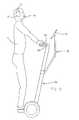
- FIG. 5is a side elevational view of a computer-equipped mobility device according to yet another embodiment of the present invention shown with an occupant.
- FIG. 6is a block diagram of the systems employed in a computer-equipped mobility device according to a preferred embodiment of the present invention.
- computer-equipped mobility device 10may include a personal mobility device 20 , a computer support member 30 , a computer 40 , a user input device support member 50 , and a user input device 60 .
- personal mobility device 20may be one of a variety of personal modes of transportation.
- personal mobility device 20may be a SEGWAYTM human transporter (trademark owned by Segway LLC), a scooter, a bicycle, a moped, or other similar device designed to transport one or two passengers over relatively short distances.
- personal mobility device 20generally includes a platform 22 , a column 24 , and handlebars 26 , each of which is conventionally known within the art and may take a variety of shapes and configurations.
- Platform 22is a rigid-surface that supports the weight of an occupant 15 (shown in FIG. 5 ) and may be designed such that an occupant 15 may sit or stand on it.
- Platform 22may be made from a variety of different materials and take a variety of different shapes.
- Column 24is a generally vertical member that includes a first end 25 and a second end 27 .
- First end 25is coupled to platform 22 such that column 24 extends upwardly from platform 22 , placing second end 27 distal platform 22 .
- Column 24can take a variety of different shapes and be made from a variety of different materials, as long as the shape and materials allow column 24 to provide sufficient support for handlebars 26 .
- Handlebars 26extend generally horizontally from second end 27 of column 24 .
- Handlebars 26may be designed to provide a stable structure that occupant 15 may use to maintain balance while on personal mobility device 20 , and/or may be designed to allow occupant 15 to steer personal mobility device 20 .
- various displays and mechanismsmay be coupled to handlebars 26 to control and monitor the function of personal mobility device 20 .
- computer support member 30couples computer 40 to personal mobility device 20 of computer-equipped mobility device 10 .
- Support member 30includes a column arm 32 and a computer arm 36 , and may be made from one or more of a variety of different materials, including metal alloys and polymers.
- Column arm 32couples at a first end 33 to column 24 and at a second end 34 to computer arm 36 .
- First end 33may couple to column 24 in a wide variety of conventionally known ways.
- first end 33may include a circular clamp 35 that grips the circumference of column 24
- column arm 32 and personal mobility device 20may include mating fasteners.
- first end 33 of column arm 32may be bolted onto personal mobility device 20 or otherwise coupled to personal mobility device 20 through the use of one of a variety of couplers, fasteners, and/or connectors.
- column arm 32may be pivotally coupled to column 24 , or alternatively, may be rigidly coupled to column 24 .
- Second end 34 of column arm 32is pivotally coupled to a first end 37 of computer arm 36 to allow computer arm 36 to pivot with respect to column arm 32 .
- the various methods of providing for such pivotingare conventionally known within the art.
- a second end 38 of computer arm 36is preferably pivotally and releasably coupled to computer 40 to allow computer 40 to pivot with respect to computer arm 36 and to be released from support member 30 if desired.
- a variety of methods and structures that are conventionally known within the artmay be used to provide the various connections described above.
- Support member 30allows occupant 15 to adjust the position of computer 40 , which gives occupant 15 the ability to position computer 40 in a location that is most comfortable to occupant 15 .
- the ability to adjust the position of computer 40also helps to ensure that computer 40 can be placed in a position that enhances the ability of occupant 15 to operate computer-equipped mobility device 10 .
- computer 40may be coupled to personal mobility device 20 through the use of a wide variety of other coupling mechanisms.
- computer 40may be coupled to personal mobility device 20 by a bracket having only one arm, or it may be rigidly coupled to personal mobility device 20 such that computer 40 would not be moveable with respect to personal mobility device 20 .
- computer 40may be given various degrees of adjustability.
- Computer 40shown as a tablet PC, is one of a variety of computers that are commercially available in the marketplace.
- computer 40may be one of a variety of personal computers, including but not limited to a laptop computer, a tablet PC, a personal digital assistant (conventionally known as a PDA), a pocket PC, or some other version of a relatively small-sized computer.
- PDApersonal digital assistant
- computer 40has its own power source, but in alternative embodiments, computer 40 may utilize the power source of personal mobility device 10 , if personal mobility device 10 includes its own source of power.
- computer-equipped mobility device 10may also include a user input device support member 50 (e.g., bracket, support, connector, coupler, arm, brace, etc.) for coupling user input device 60 to personal mobility device 20 of computer-equipped mobility device 10 .
- Support member 50which may be one of a variety of coupling devices conventionally known within the art, may take a variety of different shapes and configurations. It may also be made from one or more of a variety of different materials, including but not limited to metal alloys and/or polymers. These aspects of support member 50 may vary depending on the configuration of the user input device 60 .
- Support member 50serves to couple user input device 60 to personal mobility device 20 in such a way, and in such a location, that occupant 15 of computer-equipped mobility device 10 can use user input device 60 at the same time occupant 15 is operating personal mobility device 20 .
- support member 50preferably is configured to couple user input device 60 to personal mobility device 20 in a location close to where the hands of occupant 15 will be placed when occupant 15 is operating computer-equipped mobility device 10 .
- personal mobility device 20includes handlebars 26
- support member 50normally couples user input device 60 to handlebars 26 .
- computer-equipped mobility device 10may not include support member 50 . Rather, personal mobility device 20 may be specifically designed to incorporate or to receive a particular user input device 60 .
- computer-equipped mobility device 10may not include user input device 10 , and therefore, would not require support member 50 .
- User input device 60is coupled to support member 50 (or alternatively, to personal mobility device 20 ) and allows occupant 15 to at least partially, if not completely, control the operation of computer 40 .
- user input device 60may include a direction control member 64 and an activation member 66 that, together, mimic the operation of a conventional mouse.
- Direction control member 64 and activation member 66are located on personal mobility device 20 such that the thumb of occupant 15 may be used to operate direction control member 64 and the index finger of occupant 15 used to operate activation member 66 at the same time occupant 15 is operating personal mobility device 20 .
- user input device 60may not include direction control member 64 and activation member 66 , but rather may include a keyboard, a joystick, or other device for controlling the operation of computer 40 .
- Link 100may be accomplished through the use of wires connecting user input device 60 to computer 40 , or through the use of wireless communication.
- Various wireless communication technologiesmay be used including, but not limited to, those that make use of infrared light and/or radio frequencies, such as that used by Bluetooth compatible devices.
- a touch screen 42may be provided on computer 40 .
- Touch screen 42allows occupant 15 to dictate the operation of computer 40 by selectively applying pressure to particular portions of the display screen provided on computer 40 .
- computer 40(as well as user input device 60 and touch screen 42 through computer 40 ) may be linked to personal mobility device 20 through link 102 and used to at least partially control and/or monitor the operation of personal mobility device 20 .
- computer 40is linked to a network 90 .
- signal transmitting and receiving nodes 95may be intermittently dispersed within an area in which wireless communication capabilities are desired.
- Nodes 95are linked to network 90 through link 106 and are arranged such that when computer-equipped mobility device 10 enters the area in which nodes 95 have been dispersed, computer 40 is able to wirelessly communicate with nodes 95 through a wireless link 104 .
- Wireless link 104may be accomplished through the use of existing wireless communication technologies, including those that use infrared light and/or radio frequencies. As a result of link 104 , computer 40 is provided with access to network 90 as it travels through the area in which nodes 95 have been placed.
- computer-equipped mobility device 10enters the wireless communication area, it enters into the communication range of a particular node 95 . As computer-equipped mobility device 10 moves through the area, it eventually travels beyond the range of that particular node 95 . However, prior to leaving the range of one node 95 , it enters the range of another node 95 , which ensures that computer-equipped mobility device 10 will never be out of range of a node 95 when it is in the wireless communication area. This process is continually repeated as computer-equipped mobility device 10 moves through the wireless communication area.
- the arrangement of nodes 95may vary depending on the type of wireless technology utilized.
- network 90When computer-equipped mobility device 10 is within the network accessible area, computer 40 is linked to network 90 (through nodes 95 ) and provides occupant 15 with access to network 90 . Once provided with access to network 90 , occupant 15 is able to engage in two-way communication with network 90 (i.e. retrieve information from, and enter information into, the network) by providing commands to computer 40 (either through the use of touch screen 42 and/or user input device 60 ).
- network 90may be a hospital information system that includes various patient information and administrative information.
- the hospital information systemmay allow doctors to access patient charts, to check data generated by patient monitors, to adjust equipment settings, or to perform a multitude of other tasks.
- the systemmay also generate alerts and warnings that notify a doctor when specific events occur to patients or when other events of interest occur.
- computer 40may be linked to a variety of different networks and may provide occupant 15 with a full range of communication options when computer-equipped mobility device 10 is within the network accessible area.
- occupant 15may also be able to utilize existing technologies, such as Voice Over IP (VOIP), to receive phone calls while computer 40 is linked to network 90 .
- VOIPVoice Over IP
- the computerestablishes a link with network 90 .
- computer 40receives an incoming call through network 90 while occupant 15 is operating computer-equipped mobility device 10 .
- computer 40detects the call and generates an incoming call indication signal 130 that indicates to occupant 15 that there is an incoming call.
- Incoming call indication signal 130may be one or both of a message displayed on the computer screen (which may be touch screen 42 ) or a sound generated by computer 40 that is associated with an incoming call.
- Computer 40then awaits a signal from occupant 15 .
- occupant 15may provide a signal indicating that occupant 15 would like to answer the phone call by touching touch screen 42 in the appropriate location or by activating user input device 60 .
- user input device 60includes activation member 66 , which allows occupant 15 to signal computer 40 simply by activating activation member 66 . With activation member 66 positioned proximate where the hands of occupant 15 normally would rest while occupant 15 operates computer-equipped mobility device 10 , occupant 15 may easily signal computer 40 to answer the incoming call without substantially sacrificing the ability to operate computer-equipped mobility device 10 .
- occupant 15simply does not activate user input device 60 if occupant 15 does not wish to answer the incoming call.
- computer 40may be programmed to direct the call to the voice mail of occupant 15 , which is linked to network 90 through link 108 .
- the period of time after which computer 40 will direct the call to voice mailmay be set by occupant 15 .
- occupant 15may program computer 40 to transfer a call to voice mail after four rings, after 20 seconds, immediately if occupant 15 is presently participating in a call, or after a variety of other programmable time intervals.
- Occupant 15may also program computer 40 not to direct a call to the voice mail of occupant 15 , but rather to continue to generate incoming call indication signal 130 as long as the caller remains on the line.
- Computer-equipped mobility device 10may optionally include a headset 70 that includes a speaker 72 and a microphone 74 .
- Headset 70is linked to computer 40 through link 110 and allows occupant 15 to engage in two-way communication with computer 40 .
- Link 110may be accomplished through the use of a cord or through wireless communication.
- the wireless communicationmay utilize existing infrared light and/or radio frequency technologies, or other adequate wireless communication technologies.
- link 110is inactive until the need arises for communication between headset 70 and computer 40 .
- the link between computer 40 and headset 70is inactive prior to and at the time computer 40 detects an incoming call and generates incoming call indication signal 130 .
- occupant 15signals to computer 40 that occupant 15 desires to answer the call by activating user input device 60 (or by touching touch screen 42 in the appropriate location), this indicates to computer 40 that there is a need to activate link 110 .
- computer 40receives the signal that occupant 15 wishes to answer the call and detects whether headset 70 is present.
- step 260 aconsists of computer 40 activating link 110 .
- step 270consists of computer 40 providing a medium for two-way communication between the caller and occupant 15 .
- step 260 bconsists of computer 40 activating a link 112 with a speaker 44 and a microphone 46 (also shown in FIG. 1 ) that may be coupled to, or included within, computer 40 .
- link 112is activated, step 270 consists of computer 40 providing a medium for two-way communication between the caller and occupant 15 .
- occupant 15When occupant 15 is ready to end a call, occupant 15 simply activates user input device 60 a second time. At step 280 , computer 40 then terminates the call. During the last step 290 , computer 40 deactivates link 110 (if occupant 15 is using headset 70 ) or link 112 (if occupant is not using headset 70 ). With user input device 60 positioned proximate the location where the hands of occupant 15 normally would rest while operating computer-equipped mobility device 10 , occupant 15 may easily answer and terminate a call without substantially sacrificing the ability to operate computer-equipped mobility device 10 .
- occupant 15may also control computer 40 through the use of voice commands 80 .
- Computer 40may include voice recognition software that allows occupant 15 to control computer 40 by saying words associated with specific computer commands. For example, when computer 40 is generating an incoming call indication signal 130 , occupant 15 may say “answer,” which will cause computer 40 to answer the call. Similarly, occupant 15 may say “terminate” at the end of the call, which computer 40 will recognize as the command to terminate the call.
- Computer 40may be programmed to recognize a plurality of voice commands 80 that cause computer 40 to take one of a multitude of possible actions.
- computer 40may be linked to personal mobility device 20 through link 102 such that occupant 15 may at least partially control the operation of personal mobility device 20 by speaking voice commands 80 .
Landscapes
- Engineering & Computer Science (AREA)
- Mechanical Engineering (AREA)
- Multimedia (AREA)
- Mobile Radio Communication Systems (AREA)
Abstract
Description
Claims (24)
Priority Applications (3)
| Application Number | Priority Date | Filing Date | Title |
|---|---|---|---|
| US10/304,533US6873884B2 (en) | 2002-11-26 | 2002-11-26 | Computer-equipped mobility device and method of connecting to a network |
| DE10354928ADE10354928A1 (en) | 2002-11-26 | 2003-11-25 | Computer-equipped mobility device and method for connecting to a network |
| CNA2003101179453ACN1502514A (en) | 2002-11-26 | 2003-11-26 | Computer-equipped mobility device and method of connecting to a network |
Applications Claiming Priority (1)
| Application Number | Priority Date | Filing Date | Title |
|---|---|---|---|
| US10/304,533US6873884B2 (en) | 2002-11-26 | 2002-11-26 | Computer-equipped mobility device and method of connecting to a network |
Publications (2)
| Publication Number | Publication Date |
|---|---|
| US20040100082A1 US20040100082A1 (en) | 2004-05-27 |
| US6873884B2true US6873884B2 (en) | 2005-03-29 |
Family
ID=32325238
Family Applications (1)
| Application Number | Title | Priority Date | Filing Date |
|---|---|---|---|
| US10/304,533Expired - Fee RelatedUS6873884B2 (en) | 2002-11-26 | 2002-11-26 | Computer-equipped mobility device and method of connecting to a network |
Country Status (3)
| Country | Link |
|---|---|
| US (1) | US6873884B2 (en) |
| CN (1) | CN1502514A (en) |
| DE (1) | DE10354928A1 (en) |
Cited By (21)
| Publication number | Priority date | Publication date | Assignee | Title |
|---|---|---|---|---|
| US20040102166A1 (en)* | 2002-11-26 | 2004-05-27 | Ge Medical Systems Information Technologies, Inc. | Computer-equipped mobility device for connecting to a network |
| US20070210917A1 (en)* | 2004-08-02 | 2007-09-13 | Collins Williams F Jr | Wireless bed connectivity |
| US20070240918A1 (en)* | 2006-04-12 | 2007-10-18 | Frederick Edelblut | Mobile system and apparatus for positioning people and for supporting, positioning and transporting objects |
| US7319386B2 (en) | 2004-08-02 | 2008-01-15 | Hill-Rom Services, Inc. | Configurable system for alerting caregivers |
| US20080224861A1 (en)* | 2003-08-21 | 2008-09-18 | Mcneely Craig A | Hospital bed having wireless data capability |
| US20090056027A1 (en)* | 2007-08-29 | 2009-03-05 | Hill-Rom Services, Inc. | Mattress for a hospital bed for use in a healthcare facility and management of same |
| US20090212925A1 (en)* | 2008-02-22 | 2009-08-27 | Schuman Sr Richard Joseph | User station for healthcare communication system |
| US20090283266A1 (en)* | 2004-10-07 | 2009-11-19 | Nold Iii Raymond V | Apparatus and method for formation evaluation |
| US7868740B2 (en) | 2007-08-29 | 2011-01-11 | Hill-Rom Services, Inc. | Association of support surfaces and beds |
| US20110205062A1 (en)* | 2010-02-19 | 2011-08-25 | Pesot Whitney W | Nurse call system with additional status board |
| US20150191121A1 (en)* | 2014-01-09 | 2015-07-09 | Toyota Jidosha Kabushiki Kaisha | Display control method for inverted vehicle |
| US9411934B2 (en) | 2012-05-08 | 2016-08-09 | Hill-Rom Services, Inc. | In-room alarm configuration of nurse call system |
| US9734293B2 (en) | 2007-10-26 | 2017-08-15 | Hill-Rom Services, Inc. | System and method for association of patient care devices to a patient |
| US9830424B2 (en) | 2013-09-18 | 2017-11-28 | Hill-Rom Services, Inc. | Bed/room/patient association systems and methods |
| US10136815B2 (en) | 2012-09-24 | 2018-11-27 | Physio-Control, Inc. | Patient monitoring device with remote alert |
| US20200079468A1 (en)* | 2018-09-09 | 2020-03-12 | Manuel Saez | Small vehicle control user interface |
| US11504061B2 (en) | 2017-03-21 | 2022-11-22 | Stryker Corporation | Systems and methods for ambient energy powered physiological parameter monitoring |
| US11911325B2 (en) | 2019-02-26 | 2024-02-27 | Hill-Rom Services, Inc. | Bed interface for manual location |
| US12186241B2 (en) | 2021-01-22 | 2025-01-07 | Hill-Rom Services, Inc. | Time-based wireless pairing between a medical device and a wall unit |
| US12251243B2 (en) | 2008-02-22 | 2025-03-18 | Hill-Rom Services, Inc. | Distributed healthcare communication system |
| US12279999B2 (en) | 2021-01-22 | 2025-04-22 | Hill-Rom Services, Inc. | Wireless configuration and authorization of a wall unit that pairs with a medical device |
Families Citing this family (8)
| Publication number | Priority date | Publication date | Assignee | Title |
|---|---|---|---|---|
| US6930878B2 (en)* | 2002-11-26 | 2005-08-16 | Ge Medical Systems Information Technologies, Inc. | Computer-equipped mobility device |
| CN101565073B (en)* | 2009-04-07 | 2011-01-19 | 杨涛 | Portable streamline shaped intelligent vehicle |
| JP5569860B2 (en)* | 2010-03-26 | 2014-08-13 | 本田技研工業株式会社 | Electrical component mounting device for saddle riding type vehicles |
| CN102204859A (en)* | 2011-06-03 | 2011-10-05 | 肖伏初 | Multi-function nursing vehicle and clinical order execution system |
| CN102991629A (en)* | 2011-09-14 | 2013-03-27 | 李文嵩 | Operating device for combining intelligent mobile phone with bicycling |
| CN105101510A (en)* | 2014-05-12 | 2015-11-25 | 李文嵩 | Voice control apparatus for bicycle |
| CN104309733A (en)* | 2014-10-20 | 2015-01-28 | 浙江大学 | Electric monocycle with wireless display device |
| JP6679925B2 (en)* | 2015-12-25 | 2020-04-15 | トヨタ自動車株式会社 | Balance training equipment |
Citations (7)
| Publication number | Priority date | Publication date | Assignee | Title |
|---|---|---|---|---|
| US6282464B1 (en)* | 1997-01-28 | 2001-08-28 | American Calcar Inc. | Technique for effectively providing audio information in a vehicle |
| US20020049079A1 (en)* | 2000-05-11 | 2002-04-25 | Buckley Anthony Robert | Mobile station for telecommunications system |
| US6526335B1 (en)* | 2000-01-24 | 2003-02-25 | G. Victor Treyz | Automobile personal computer systems |
| US20030065432A1 (en)* | 1999-03-12 | 2003-04-03 | Valerie Shuman | Method and system for an in-vehicle computing architecture |
| US20030224839A1 (en)* | 2002-01-30 | 2003-12-04 | Tsutomu Takahashi | Mobile communication device with a retractable headset kit and automatic call control |
| US20040024502A1 (en)* | 1999-07-30 | 2004-02-05 | Oshkosh Truck Corporation | Equipment service vehicle with remote monitoring |
| US20040081309A1 (en)* | 2002-10-29 | 2004-04-29 | International Business Machines Corporation | Method for processing calls in a call center with automatic answering |
- 2002
- 2002-11-26USUS10/304,533patent/US6873884B2/ennot_activeExpired - Fee Related
- 2003
- 2003-11-25DEDE10354928Apatent/DE10354928A1/ennot_activeWithdrawn
- 2003-11-26CNCNA2003101179453Apatent/CN1502514A/enactivePending
Patent Citations (7)
| Publication number | Priority date | Publication date | Assignee | Title |
|---|---|---|---|---|
| US6282464B1 (en)* | 1997-01-28 | 2001-08-28 | American Calcar Inc. | Technique for effectively providing audio information in a vehicle |
| US20030065432A1 (en)* | 1999-03-12 | 2003-04-03 | Valerie Shuman | Method and system for an in-vehicle computing architecture |
| US20040024502A1 (en)* | 1999-07-30 | 2004-02-05 | Oshkosh Truck Corporation | Equipment service vehicle with remote monitoring |
| US6526335B1 (en)* | 2000-01-24 | 2003-02-25 | G. Victor Treyz | Automobile personal computer systems |
| US20020049079A1 (en)* | 2000-05-11 | 2002-04-25 | Buckley Anthony Robert | Mobile station for telecommunications system |
| US20030224839A1 (en)* | 2002-01-30 | 2003-12-04 | Tsutomu Takahashi | Mobile communication device with a retractable headset kit and automatic call control |
| US20040081309A1 (en)* | 2002-10-29 | 2004-04-29 | International Business Machines Corporation | Method for processing calls in a call center with automatic answering |
Non-Patent Citations (12)
| Title |
|---|
| Amazon.com, "Segway Human Transporter", available at http://www.amazon.com/exec/obidos/tg/detail/-/B00007EPJ6/ref=dp_seg_cent_3/103-8514163-4131062?v=glance&s=electronics&vi=pictures (available at least as of Nov. 28, 2002). |
| Amazon.com: Electronics, "Segway Human Transporter," available at http:/www.amazon.com/exec/obidos/tg/detail/-/B00007EPJ6/103-8514163-4131062?vi=glance (available at least as of Nov. 28, 2002). |
| Dell-Dell Notebooks, "Choose a Notebook Line", available at http://www.dell.com/us/en/gen/products/line_notebooks.htm (available at least as of Nov. 28, 2002). |
| Dell-Which Dell Notebook is Right for you?, available at http://www.dell.com/us/en/gen/topics/sbtopic_001_learningnb-whichnb.htm (available at least as of Nov. 28, 2002). |
| Fujitsu PC Corporation-Tablet PCs, "ST4000 Tablet PC," available at http://www.fujitsupc.com/www/products_pentablets.shtml?products/pentablets/st4000a (available at least as of Nov. 28, 2002). |
| Gateway Accessory Store, "Cordless Optical Mouse," available at http://accessories.gateway.com/AccessoryStore/Hardware_316441/Input+Devices_316608/Mice_316612/1828439_ProdDetail.htm (available at least as of Nov. 28, 2002). |
| Gateway Accessory Store, "Web Pro Optical Mouse", available at http://accessories.gateway.com/AccessoryStore/Hardware_316441/Input+Devices_316608/Mice_316612/1830069_ProdDetail.htm (available at least as of Nov. 28, 2002). |
| Gateway Computers-Gateway Tablet PCb, available at Http://www.gateway.com/work/prod/sb_tabletpcb_ProdDetail.shtml (available at least as of Nov. 28, 2002). |
| Palm Products: Palm m515 Handheld, available at http://www.palm.com/products/palmm515/ (available at least as of Nov. 28, 2002). |
| Palm Products-Handhelds, "The Palm Handheld Family," available at http://www.palm.com/products/handhelds/ (available at least as of Nov. 28, 2002). |
| Palm Products-Tungsten W Handheld, available at http://www.palm.com/products/handhelds/tungsten-w/ (available at least as of Nov. 28, 2002). |
| Segway, Segway HT, "Maximize your abilities. Minimize your presence.", available at http://www.segway.com/segway/ (available at least as of Nov. 28, 2002). |
Cited By (86)
| Publication number | Priority date | Publication date | Assignee | Title |
|---|---|---|---|---|
| US20040102166A1 (en)* | 2002-11-26 | 2004-05-27 | Ge Medical Systems Information Technologies, Inc. | Computer-equipped mobility device for connecting to a network |
| US7200427B2 (en)* | 2002-11-26 | 2007-04-03 | Ge Medical Systems Information Technologies, Inc. | Computer-equipped mobility device for connecting to a network |
| US9572737B2 (en) | 2003-08-21 | 2017-02-21 | Hill-Rom Services, Inc. | Hospital bed having communication modules |
| US10206837B2 (en) | 2003-08-21 | 2019-02-19 | Hill-Rom Services, Inc. | Hospital bed and room communication modules |
| US9142923B2 (en) | 2003-08-21 | 2015-09-22 | Hill-Rom Services, Inc. | Hospital bed having wireless data and locating capability |
| US8272892B2 (en) | 2003-08-21 | 2012-09-25 | Hill-Rom Services, Inc. | Hospital bed having wireless data capability |
| US20080224861A1 (en)* | 2003-08-21 | 2008-09-18 | Mcneely Craig A | Hospital bed having wireless data capability |
| US9925104B2 (en) | 2003-08-21 | 2018-03-27 | Hill-Rom Services, Inc. | Hospital bed and room communication modules |
| US8866598B2 (en) | 2004-08-02 | 2014-10-21 | Hill-Rom Services, Inc. | Healthcare communication system with whiteboard |
| US9861321B2 (en) | 2004-08-02 | 2018-01-09 | Hill-Rom Services, Inc. | Bed alarm communication system |
| US10548475B2 (en) | 2004-08-02 | 2020-02-04 | Hill-Rom Services, Inc. | Method of hospital bed network connectivity |
| US8917166B2 (en) | 2004-08-02 | 2014-12-23 | Hill-Rom Services, Inc. | Hospital bed networking system and method |
| US20100079276A1 (en)* | 2004-08-02 | 2010-04-01 | Collins Jr Williams F | Hospital bed with network interface unit |
| US7746218B2 (en) | 2004-08-02 | 2010-06-29 | Hill-Rom Services, Inc. | Configurable system for alerting caregivers |
| US7852208B2 (en) | 2004-08-02 | 2010-12-14 | Hill-Rom Services, Inc. | Wireless bed connectivity |
| US10278582B2 (en) | 2004-08-02 | 2019-05-07 | Hill-Rom Services, Inc. | Hospital bed having wired and wireless network connectivity |
| US20110074571A1 (en)* | 2004-08-02 | 2011-03-31 | Collins Jr Williams F | Wireless bed connectivity |
| US10978191B2 (en) | 2004-08-02 | 2021-04-13 | Hill-Rom Services, Inc. | Healthcare communication method having configurable alarm rules |
| US9050031B2 (en) | 2004-08-02 | 2015-06-09 | Hill-Rom Services, Inc. | Healthcare communication system having configurable alarm rules |
| US10098593B2 (en) | 2004-08-02 | 2018-10-16 | Hill-Rom Services, Inc. | Bed alert communication method |
| US10070789B2 (en) | 2004-08-02 | 2018-09-11 | Hill-Rom Services, Inc. | Hospital bed having wired and wireless network connectivity |
| US11508469B2 (en) | 2004-08-02 | 2022-11-22 | Hill-Rom Services, Inc. | Hospital bed having wireless network connectivity |
| US8120471B2 (en) | 2004-08-02 | 2012-02-21 | Hill-Rom Services, Inc. | Hospital bed with network interface unit |
| US20070210917A1 (en)* | 2004-08-02 | 2007-09-13 | Collins Williams F Jr | Wireless bed connectivity |
| US20080094207A1 (en)* | 2004-08-02 | 2008-04-24 | Collins Williams F Jr | Configurable system for alerting caregivers |
| US8284047B2 (en) | 2004-08-02 | 2012-10-09 | Hill-Rom Services, Inc. | Wireless bed connectivity |
| US9775519B2 (en) | 2004-08-02 | 2017-10-03 | Hill-Rom Services, Inc. | Network connectivity unit for hospital bed |
| US8604917B2 (en) | 2004-08-02 | 2013-12-10 | Hill-Rom Services, Inc. | Hospital bed having user input to enable and suspend remote monitoring of alert conditions |
| US8421606B2 (en) | 2004-08-02 | 2013-04-16 | Hill-Rom Services, Inc. | Wireless bed locating system |
| US9517034B2 (en) | 2004-08-02 | 2016-12-13 | Hill-Rom Services, Inc. | Healthcare communication system for programming bed alarms |
| US9513899B2 (en) | 2004-08-02 | 2016-12-06 | Hill-Rom Services, Inc. | System wide firmware updates to networked hospital beds |
| US8536990B2 (en) | 2004-08-02 | 2013-09-17 | Hill-Rom Services, Inc. | Hospital bed with nurse call system interface unit |
| US9336672B2 (en) | 2004-08-02 | 2016-05-10 | Hill-Rom Services, Inc. | Healthcare communication system for programming bed alarms |
| US7319386B2 (en) | 2004-08-02 | 2008-01-15 | Hill-Rom Services, Inc. | Configurable system for alerting caregivers |
| US20090283266A1 (en)* | 2004-10-07 | 2009-11-19 | Nold Iii Raymond V | Apparatus and method for formation evaluation |
| US7992881B2 (en) | 2006-04-12 | 2011-08-09 | Frederick Edelblut | Mobile system and apparatus for positioning people and for supporting, positioning and transporting objects |
| US20070240918A1 (en)* | 2006-04-12 | 2007-10-18 | Frederick Edelblut | Mobile system and apparatus for positioning people and for supporting, positioning and transporting objects |
| US10566088B2 (en) | 2007-08-29 | 2020-02-18 | Hill-Rom Services, Inc. | Wireless bed locating system |
| US12230389B2 (en) | 2007-08-29 | 2025-02-18 | Hill-Rom Services, Inc. | Wireless bed locating system |
| US11574736B2 (en) | 2007-08-29 | 2023-02-07 | Hill-Rom Services, Inc. | Wireless bed and surface locating system |
| US20090056027A1 (en)* | 2007-08-29 | 2009-03-05 | Hill-Rom Services, Inc. | Mattress for a hospital bed for use in a healthcare facility and management of same |
| US8604916B2 (en) | 2007-08-29 | 2013-12-10 | Hill-Rom Services, Inc. | Association of support surfaces and beds |
| US10886024B2 (en) | 2007-08-29 | 2021-01-05 | Hill-Rom Services, Inc. | Bed having housekeeping request button |
| US7868740B2 (en) | 2007-08-29 | 2011-01-11 | Hill-Rom Services, Inc. | Association of support surfaces and beds |
| US20110072583A1 (en)* | 2007-08-29 | 2011-03-31 | Mcneely Craig A | Association of support surfaces and beds |
| US8461968B2 (en) | 2007-08-29 | 2013-06-11 | Hill-Rom Services, Inc. | Mattress for a hospital bed for use in a healthcare facility and management of same |
| US8031057B2 (en) | 2007-08-29 | 2011-10-04 | Hill-Rom Services, Inc. | Association of support surfaces and beds |
| US9734293B2 (en) | 2007-10-26 | 2017-08-15 | Hill-Rom Services, Inc. | System and method for association of patient care devices to a patient |
| US11031130B2 (en) | 2007-10-26 | 2021-06-08 | Hill-Rom Services, Inc. | Patient support apparatus having data collection and communication capability |
| US8392747B2 (en) | 2008-02-22 | 2013-03-05 | Hill-Rom Services, Inc. | Distributed fault tolerant architecture for a healthcare communication system |
| US11058368B2 (en) | 2008-02-22 | 2021-07-13 | Hill-Rom Services, Inc. | Distributed healthcare communication system |
| US8456286B2 (en) | 2008-02-22 | 2013-06-04 | Hill-Rom Services, Inc. | User station for healthcare communication system |
| US8384526B2 (en) | 2008-02-22 | 2013-02-26 | Hill-Rom Services, Inc. | Indicator apparatus for healthcare communication system |
| US12251243B2 (en) | 2008-02-22 | 2025-03-18 | Hill-Rom Services, Inc. | Distributed healthcare communication system |
| US8169304B2 (en) | 2008-02-22 | 2012-05-01 | Hill-Rom Services, Inc. | User station for healthcare communication system |
| US8046625B2 (en) | 2008-02-22 | 2011-10-25 | Hill-Rom Services, Inc. | Distributed fault tolerant architecture for a healthcare communication system |
| US9955926B2 (en) | 2008-02-22 | 2018-05-01 | Hill-Rom Services, Inc. | Distributed healthcare communication system |
| US9517035B2 (en) | 2008-02-22 | 2016-12-13 | Hill-Rom Services, Inc. | Distributed healthcare communication system |
| US11696731B2 (en) | 2008-02-22 | 2023-07-11 | Hill-Room Services, Inc. | Distributed healthcare communication method |
| US8803669B2 (en) | 2008-02-22 | 2014-08-12 | Hill-Rom Services, Inc. | User station for healthcare communication system |
| US9235979B2 (en) | 2008-02-22 | 2016-01-12 | Hill-Rom Services, Inc. | User station for healthcare communication system |
| US8598995B2 (en) | 2008-02-22 | 2013-12-03 | Hill-Rom Services, Inc. | Distributed healthcare communication system |
| US10307113B2 (en) | 2008-02-22 | 2019-06-04 | Hill-Rom Services, Inc. | Distributed healthcare communication system |
| US20090212956A1 (en)* | 2008-02-22 | 2009-08-27 | Schuman Richard J | Distributed healthcare communication system |
| US20090217080A1 (en)* | 2008-02-22 | 2009-08-27 | Ferguson David C | Distributed fault tolerant architecture for a healthcare communication system |
| US8762766B2 (en) | 2008-02-22 | 2014-06-24 | Hill-Rom Services, Inc. | Distributed fault tolerant architecture for a healthcare communication system |
| US10638983B2 (en) | 2008-02-22 | 2020-05-05 | Hill-Rom Services, Inc. | Distributed healthcare communication system |
| US9299242B2 (en) | 2008-02-22 | 2016-03-29 | Hill-Rom Services, Inc. | Distributed healthcare communication system |
| US20090212925A1 (en)* | 2008-02-22 | 2009-08-27 | Schuman Sr Richard Joseph | User station for healthcare communication system |
| US11944467B2 (en) | 2008-02-22 | 2024-04-02 | Hill-Rom Services, Inc. | Distributed healthcare communication system |
| US8779924B2 (en) | 2010-02-19 | 2014-07-15 | Hill-Rom Services, Inc. | Nurse call system with additional status board |
| US20110205062A1 (en)* | 2010-02-19 | 2011-08-25 | Pesot Whitney W | Nurse call system with additional status board |
| US9411934B2 (en) | 2012-05-08 | 2016-08-09 | Hill-Rom Services, Inc. | In-room alarm configuration of nurse call system |
| US10136815B2 (en) | 2012-09-24 | 2018-11-27 | Physio-Control, Inc. | Patient monitoring device with remote alert |
| US11457808B2 (en) | 2012-09-24 | 2022-10-04 | Physio-Control, Inc. | Patient monitoring device with remote alert |
| US12064207B2 (en) | 2012-09-24 | 2024-08-20 | Physio-Control, Inc. | Patient monitoring device with remote alert |
| US11011267B2 (en) | 2013-09-18 | 2021-05-18 | Hill-Rom Services, Inc. | Bed/room/patient association systems and methods |
| US9830424B2 (en) | 2013-09-18 | 2017-11-28 | Hill-Rom Services, Inc. | Bed/room/patient association systems and methods |
| US12354731B2 (en) | 2013-09-18 | 2025-07-08 | Hill-Rom Services, Inc. | Bed/room/patient association systems and methods |
| US20150191121A1 (en)* | 2014-01-09 | 2015-07-09 | Toyota Jidosha Kabushiki Kaisha | Display control method for inverted vehicle |
| US11504061B2 (en) | 2017-03-21 | 2022-11-22 | Stryker Corporation | Systems and methods for ambient energy powered physiological parameter monitoring |
| US20200079468A1 (en)* | 2018-09-09 | 2020-03-12 | Manuel Saez | Small vehicle control user interface |
| US11911325B2 (en) | 2019-02-26 | 2024-02-27 | Hill-Rom Services, Inc. | Bed interface for manual location |
| US12396907B2 (en) | 2019-02-26 | 2025-08-26 | Hill-Rom Services, Inc. | Bed interface for manual location |
| US12186241B2 (en) | 2021-01-22 | 2025-01-07 | Hill-Rom Services, Inc. | Time-based wireless pairing between a medical device and a wall unit |
| US12279999B2 (en) | 2021-01-22 | 2025-04-22 | Hill-Rom Services, Inc. | Wireless configuration and authorization of a wall unit that pairs with a medical device |
Also Published As
| Publication number | Publication date |
|---|---|
| US20040100082A1 (en) | 2004-05-27 |
| CN1502514A (en) | 2004-06-09 |
| DE10354928A1 (en) | 2004-06-24 |
Similar Documents
| Publication | Publication Date | Title |
|---|---|---|
| US6873884B2 (en) | Computer-equipped mobility device and method of connecting to a network | |
| US7200427B2 (en) | Computer-equipped mobility device for connecting to a network | |
| US6930878B2 (en) | Computer-equipped mobility device | |
| EP2359362B1 (en) | Training/coaching system for a voice-enabled work environment | |
| CN102473081B (en) | Portable telepresence apparatus | |
| US9999557B2 (en) | Robotic mobility device | |
| CN110971423B (en) | Group creation method and electronic device | |
| WO2002080126A2 (en) | Hospital bed and network system | |
| US8363646B2 (en) | Application server for dispatching physiological signals in a hospital, in real time | |
| EP1617361A4 (en) | At-home medical examination system and at-home medical examination method | |
| CN106982286B (en) | A recording method, device and computer-readable storage medium | |
| TW200507596A (en) | Communications device processor peripheral | |
| US8794766B2 (en) | System and method for physically disabled persons to read e-publications | |
| KR101555828B1 (en) | An application server for reducing ambiance noise in an auscultation signal, and for recording comments while auscultating a patient with an electronic stethoscope | |
| US20200237471A1 (en) | Smart Mobile Cart for Nursing and Caring | |
| JP2007150702A (en) | Nurse call system | |
| JP2003283680A (en) | Voice identifying nurse calling system | |
| GB2629852A (en) | Portable translator-interface apparatus | |
| JP2008134752A (en) | Waiting room information system | |
| CN120812419A (en) | Intelligent medical care patient call intercom system, device and method | |
| Doughty et al. | Automated care in the community—an engineer’s dream, a health professional’s dilemma? | |
| JP2005071226A (en) | Care support system, care support method, care support center side device program, and care receiver side device program |
Legal Events
| Date | Code | Title | Description |
|---|---|---|---|
| AS | Assignment | Owner name:GE MEDICAL SYSTEMS INFORMATION TECHNOLOGIES, INC., Free format text:ASSIGNMENT OF ASSIGNORS INTEREST;ASSIGNORS:BRACKETT, C. CAMERON;FORS, STEVEN L.;MORITA, MARK M.;REEL/FRAME:013855/0846 Effective date:20030224 | |
| FEPP | Fee payment procedure | Free format text:PAYOR NUMBER ASSIGNED (ORIGINAL EVENT CODE: ASPN); ENTITY STATUS OF PATENT OWNER: LARGE ENTITY | |
| REMI | Maintenance fee reminder mailed | ||
| REIN | Reinstatement after maintenance fee payment confirmed | ||
| FP | Lapsed due to failure to pay maintenance fee | Effective date:20090329 | |
| FEPP | Fee payment procedure | Free format text:PAYOR NUMBER ASSIGNED (ORIGINAL EVENT CODE: ASPN); ENTITY STATUS OF PATENT OWNER: LARGE ENTITY Free format text:PAYER NUMBER DE-ASSIGNED (ORIGINAL EVENT CODE: RMPN); ENTITY STATUS OF PATENT OWNER: LARGE ENTITY | |
| PRDP | Patent reinstated due to the acceptance of a late maintenance fee | Effective date:20100526 | |
| AS | Assignment | Owner name:GENERAL ELECTRIC COMPANY,NEW YORK Free format text:ASSIGNMENT OF ASSIGNORS INTEREST;ASSIGNOR:GE MEDICAL SYSTEMS INFORMATION TECHNOLOGIES, INC.;REEL/FRAME:024434/0701 Effective date:20100525 | |
| FPAY | Fee payment | Year of fee payment:4 | |
| SULP | Surcharge for late payment | ||
| FPAY | Fee payment | Year of fee payment:8 | |
| REMI | Maintenance fee reminder mailed | ||
| LAPS | Lapse for failure to pay maintenance fees | ||
| STCH | Information on status: patent discontinuation | Free format text:PATENT EXPIRED DUE TO NONPAYMENT OF MAINTENANCE FEES UNDER 37 CFR 1.362 | |
| FP | Lapsed due to failure to pay maintenance fee | Effective date:20170329 |