US6873868B2 - Multi-fiber catheter probe arrangement for tissue analysis or treatment - Google Patents
Multi-fiber catheter probe arrangement for tissue analysis or treatmentDownload PDFInfo
- Publication number
- US6873868B2 US6873868B2US10/037,307US3730701AUS6873868B2US 6873868 B2US6873868 B2US 6873868B2US 3730701 AUS3730701 AUS 3730701AUS 6873868 B2US6873868 B2US 6873868B2
- Authority
- US
- United States
- Prior art keywords
- catheter tip
- recited
- fibers
- tip apparatus
- energy
- Prior art date
- Legal status (The legal status is an assumption and is not a legal conclusion. Google has not performed a legal analysis and makes no representation as to the accuracy of the status listed.)
- Expired - Lifetime, expires
Links
- 239000000835fiberSubstances0.000titleclaimsabstractdescription171
- 238000004458analytical methodMethods0.000titleclaimsabstractdescription32
- 239000000523sampleSubstances0.000titleclaimsdescription61
- 238000004891communicationMethods0.000claimsabstractdescription21
- 239000013307optical fiberSubstances0.000claimsdescription7
- 230000004323axial lengthEffects0.000claimsdescription6
- 230000005540biological transmissionEffects0.000claimsdescription2
- 238000001125extrusionMethods0.000description17
- 230000003287optical effectEffects0.000description7
- 238000006073displacement reactionMethods0.000description5
- 230000000694effectsEffects0.000description5
- 238000003745diagnosisMethods0.000description4
- 230000002093peripheral effectEffects0.000description4
- 238000000926separation methodMethods0.000description3
- 238000001228spectrumMethods0.000description3
- 230000004075alterationEffects0.000description2
- HVYWMOMLDIMFJA-DPAQBDIFSA-NcholesterolChemical compoundC1C=C2C[C@@H](O)CC[C@]2(C)[C@@H]2[C@@H]1[C@@H]1CC[C@H]([C@H](C)CCCC(C)C)[C@@]1(C)CC2HVYWMOMLDIMFJA-DPAQBDIFSA-N0.000description2
- 238000010336energy treatmentMethods0.000description2
- 238000001727in vivoMethods0.000description2
- 210000000056organAnatomy0.000description2
- 238000002604ultrasonographyMethods0.000description2
- 238000010521absorption reactionMethods0.000description1
- 230000003044adaptive effectEffects0.000description1
- 239000008280bloodSubstances0.000description1
- 210000004369bloodAnatomy0.000description1
- 235000012000cholesterolNutrition0.000description1
- 239000000470constituentSubstances0.000description1
- 238000005286illuminationMethods0.000description1
- 238000003780insertionMethods0.000description1
- 230000037431insertionEffects0.000description1
- 238000003754machiningMethods0.000description1
- 238000000034methodMethods0.000description1
- 238000000465mouldingMethods0.000description1
Images


Classifications
- A—HUMAN NECESSITIES
- A61—MEDICAL OR VETERINARY SCIENCE; HYGIENE
- A61B—DIAGNOSIS; SURGERY; IDENTIFICATION
- A61B1/00—Instruments for performing medical examinations of the interior of cavities or tubes of the body by visual or photographical inspection, e.g. endoscopes; Illuminating arrangements therefor
- A61B1/00064—Constructional details of the endoscope body
- A61B1/00071—Insertion part of the endoscope body
- A61B1/00073—Insertion part of the endoscope body with externally grooved shaft
- A—HUMAN NECESSITIES
- A61—MEDICAL OR VETERINARY SCIENCE; HYGIENE
- A61B—DIAGNOSIS; SURGERY; IDENTIFICATION
- A61B1/00—Instruments for performing medical examinations of the interior of cavities or tubes of the body by visual or photographical inspection, e.g. endoscopes; Illuminating arrangements therefor
- A61B1/00064—Constructional details of the endoscope body
- A61B1/00071—Insertion part of the endoscope body
- A61B1/0008—Insertion part of the endoscope body characterised by distal tip features
- A61B1/00096—Optical elements
- A—HUMAN NECESSITIES
- A61—MEDICAL OR VETERINARY SCIENCE; HYGIENE
- A61B—DIAGNOSIS; SURGERY; IDENTIFICATION
- A61B1/00—Instruments for performing medical examinations of the interior of cavities or tubes of the body by visual or photographical inspection, e.g. endoscopes; Illuminating arrangements therefor
- A61B1/06—Instruments for performing medical examinations of the interior of cavities or tubes of the body by visual or photographical inspection, e.g. endoscopes; Illuminating arrangements therefor with illuminating arrangements
- A61B1/0615—Instruments for performing medical examinations of the interior of cavities or tubes of the body by visual or photographical inspection, e.g. endoscopes; Illuminating arrangements therefor with illuminating arrangements for radial illumination
- A—HUMAN NECESSITIES
- A61—MEDICAL OR VETERINARY SCIENCE; HYGIENE
- A61B—DIAGNOSIS; SURGERY; IDENTIFICATION
- A61B1/00—Instruments for performing medical examinations of the interior of cavities or tubes of the body by visual or photographical inspection, e.g. endoscopes; Illuminating arrangements therefor
- A61B1/06—Instruments for performing medical examinations of the interior of cavities or tubes of the body by visual or photographical inspection, e.g. endoscopes; Illuminating arrangements therefor with illuminating arrangements
- A61B1/07—Instruments for performing medical examinations of the interior of cavities or tubes of the body by visual or photographical inspection, e.g. endoscopes; Illuminating arrangements therefor with illuminating arrangements using light-conductive means, e.g. optical fibres
- A—HUMAN NECESSITIES
- A61—MEDICAL OR VETERINARY SCIENCE; HYGIENE
- A61B—DIAGNOSIS; SURGERY; IDENTIFICATION
- A61B18/00—Surgical instruments, devices or methods for transferring non-mechanical forms of energy to or from the body
- A61B18/18—Surgical instruments, devices or methods for transferring non-mechanical forms of energy to or from the body by applying electromagnetic radiation, e.g. microwaves
- A61B18/20—Surgical instruments, devices or methods for transferring non-mechanical forms of energy to or from the body by applying electromagnetic radiation, e.g. microwaves using laser
- A61B18/22—Surgical instruments, devices or methods for transferring non-mechanical forms of energy to or from the body by applying electromagnetic radiation, e.g. microwaves using laser the beam being directed along or through a flexible conduit, e.g. an optical fibre; Couplings or hand-pieces therefor
- A61B18/24—Surgical instruments, devices or methods for transferring non-mechanical forms of energy to or from the body by applying electromagnetic radiation, e.g. microwaves using laser the beam being directed along or through a flexible conduit, e.g. an optical fibre; Couplings or hand-pieces therefor with a catheter
- A—HUMAN NECESSITIES
- A61—MEDICAL OR VETERINARY SCIENCE; HYGIENE
- A61B—DIAGNOSIS; SURGERY; IDENTIFICATION
- A61B1/00—Instruments for performing medical examinations of the interior of cavities or tubes of the body by visual or photographical inspection, e.g. endoscopes; Illuminating arrangements therefor
- A61B1/313—Instruments for performing medical examinations of the interior of cavities or tubes of the body by visual or photographical inspection, e.g. endoscopes; Illuminating arrangements therefor for introducing through surgical openings, e.g. laparoscopes
- A61B1/3137—Instruments for performing medical examinations of the interior of cavities or tubes of the body by visual or photographical inspection, e.g. endoscopes; Illuminating arrangements therefor for introducing through surgical openings, e.g. laparoscopes for examination of the interior of blood vessels
- A—HUMAN NECESSITIES
- A61—MEDICAL OR VETERINARY SCIENCE; HYGIENE
- A61B—DIAGNOSIS; SURGERY; IDENTIFICATION
- A61B17/00—Surgical instruments, devices or methods
- A61B2017/00017—Electrical control of surgical instruments
- A61B2017/00022—Sensing or detecting at the treatment site
- A61B2017/00057—Light
- A—HUMAN NECESSITIES
- A61—MEDICAL OR VETERINARY SCIENCE; HYGIENE
- A61B—DIAGNOSIS; SURGERY; IDENTIFICATION
- A61B18/00—Surgical instruments, devices or methods for transferring non-mechanical forms of energy to or from the body
- A61B18/18—Surgical instruments, devices or methods for transferring non-mechanical forms of energy to or from the body by applying electromagnetic radiation, e.g. microwaves
- A61B18/20—Surgical instruments, devices or methods for transferring non-mechanical forms of energy to or from the body by applying electromagnetic radiation, e.g. microwaves using laser
- A61B2018/208—Surgical instruments, devices or methods for transferring non-mechanical forms of energy to or from the body by applying electromagnetic radiation, e.g. microwaves using laser with multiple treatment beams not sharing a common path, e.g. non-axial or parallel
- A—HUMAN NECESSITIES
- A61—MEDICAL OR VETERINARY SCIENCE; HYGIENE
- A61B—DIAGNOSIS; SURGERY; IDENTIFICATION
- A61B18/00—Surgical instruments, devices or methods for transferring non-mechanical forms of energy to or from the body
- A61B18/18—Surgical instruments, devices or methods for transferring non-mechanical forms of energy to or from the body by applying electromagnetic radiation, e.g. microwaves
- A61B18/20—Surgical instruments, devices or methods for transferring non-mechanical forms of energy to or from the body by applying electromagnetic radiation, e.g. microwaves using laser
- A61B18/22—Surgical instruments, devices or methods for transferring non-mechanical forms of energy to or from the body by applying electromagnetic radiation, e.g. microwaves using laser the beam being directed along or through a flexible conduit, e.g. an optical fibre; Couplings or hand-pieces therefor
- A61B2018/2205—Characteristics of fibres
- A61B2018/2211—Plurality of fibres
- A—HUMAN NECESSITIES
- A61—MEDICAL OR VETERINARY SCIENCE; HYGIENE
- A61B—DIAGNOSIS; SURGERY; IDENTIFICATION
- A61B18/00—Surgical instruments, devices or methods for transferring non-mechanical forms of energy to or from the body
- A61B18/18—Surgical instruments, devices or methods for transferring non-mechanical forms of energy to or from the body by applying electromagnetic radiation, e.g. microwaves
- A61B18/20—Surgical instruments, devices or methods for transferring non-mechanical forms of energy to or from the body by applying electromagnetic radiation, e.g. microwaves using laser
- A61B18/22—Surgical instruments, devices or methods for transferring non-mechanical forms of energy to or from the body by applying electromagnetic radiation, e.g. microwaves using laser the beam being directed along or through a flexible conduit, e.g. an optical fibre; Couplings or hand-pieces therefor
- A61B2018/2255—Optical elements at the distal end of probe tips
- A61B2018/2272—Optical elements at the distal end of probe tips with reflective or refractive surfaces for deflecting the beam
- A—HUMAN NECESSITIES
- A61—MEDICAL OR VETERINARY SCIENCE; HYGIENE
- A61B—DIAGNOSIS; SURGERY; IDENTIFICATION
- A61B5/00—Measuring for diagnostic purposes; Identification of persons
- A61B5/0059—Measuring for diagnostic purposes; Identification of persons using light, e.g. diagnosis by transillumination, diascopy, fluorescence
- A61B5/0082—Measuring for diagnostic purposes; Identification of persons using light, e.g. diagnosis by transillumination, diascopy, fluorescence adapted for particular medical purposes
- A61B5/0084—Measuring for diagnostic purposes; Identification of persons using light, e.g. diagnosis by transillumination, diascopy, fluorescence adapted for particular medical purposes for introduction into the body, e.g. by catheters
Definitions
- This inventionrelates to photo-medical devices, and more particularly to photo-medical devices that deliver and collect radiant energy to permit body tissue analysis and/or treatment, and is co-pending with commonly assigned U.S. patent application Ser No. 10/037,307 filed on Dec. 31, 2001, entitled “Catheter Probe Arrangement for Tissue Analysis by Radiant Energy Delivery and Radiant Energy Collection” which is incorporated herein by reference in its entirety.
- the sensing and treating of various tissue characteristics in the in vivo intravascular environmentis desirous for many reasons yet difficult because it is a very harsh environment in which to conduct such analysis or treatment.
- the presence of blood and its constituents such as cholesterolmay effect scattering and absorption of energy signals transmitted within an organ.
- Diagnosis and treatment of various tissues within the human body using an in vivo probenecessitates adaptive characteristics for that probe when it is inserted into a mammalian body organ.
- wave energy transmittingi.e. photonic
- the present inventionprovides a catheter probe apparatus and method of use of a catheter probe apparatus to analyze body tissue using a component of the energy spectrum for analysis which energy is distributed and received by an elongated multi fiber probe introduceable through a catheter into that body tissue.
- introduction of a body probemay be done through an endoscope, or other catheter-like devices for energy diagnosis and treatment of that tissue.
- the probe of the present inventioncomprises an elongated generally cylindrically shaped housing having a first or distal and a second or proximal end.
- the housingin a first preferred embodiment has a central bore therethrough, which may be characterized as a lumen for receiving other elongated devices such as a guidewire or signal carrying fibers.
- the housinghas an outer peripheral surface having a plurality of spaced apart, parallel, longitudinally directed alignment grooves thereon.
- a step-like ledge or shouldermay be arranged transversely with respect to the longitudinal axis of the alignment grooves to act as an abutment or stop for each flexible signal fiber disposed within the respective alignment grooves.
- An enlarged generally radially directed flangeis disposed at the distal most end of the alignment grooves, on the distalmost end of the probe housing.
- the flangemay have a reflective surface thereon for directing light energy rays carried by the signal carrying fibers, as will be disclosed hereinbelow. It is contemplated that there may be from eight to twelve or more alignment grooves spaced about the periphery of the housing of the probe of the present invention.
- the ledges or shoulders arranged within the trough of the alignment groovesmay be aligned in common radial plane or aligned in a number of parallel spaced apart radially directed planes with respect to the longitudinal axis of the housing.
- the ledges or shouldersmay be of varying radial distances in height and angled so as to effect radial displacement of the fiber tips from the radialy inner surface of the respective angular groove in which it is disposed.
- a further embodiment of the housing comprising the elongated probeincludes a central bore or lumen through which a signal delivery fiber may be longitudinally adjustably disposed.
- the delivery fiberwould preferably have a polished conical tip on its distalmost end.
- the elongated housing in this embodimentwould have the plurality of parallel longitudinally directed alignment grooves spaced apart about its periphery, each of the alignment grooves having a longitudinally adjustable return fiber disposed therein.
- Each of the return fiberswould have a polished distal face arranged at an angle with respect to its own longitudinal axis. The polished face would function as a reflective surface for incoming light energy rays to be reflected in a return path longitudinally within the return fibers.
- the probe or elongated housingwould be longitudinally displaceable within an outermost catheter sheath.
- a further embodimentis contemplated with a generally cylindrically shaped housing having a central bore which functions as a lumen for a guide wire or further light energy bearing fiber.
- the outer surface of the elongated probehas the aforementioned plurality of elongated alignment channels or grooves fabricated therein, with each of the elongated grooves having a flexible, light carrying fiber therein.
- Alternating circumferentially arranged fibers in this embodimentmay comprise a delivery fiber and a return signal fiber.
- the delivery signal fiber and the return signal fibersmay each have a polished face on its distalmost end thereon, each face disposed at an angle of about 45 degrees with respect to its longitudinal axis thereof. It is further contemplated that each individual deliver or return signal fiber may be longitudinally displaceable within their respective alignment grooves for adjustment of the desired analysis and/or treatment to mammalian body tissue being treated.
- Another further embodiment of the present inventioncontemplates the elongated generally cylindrically shaped probe having a proximal portion of reduced diameter, a central portion having a plurality of generally parallel spaced apart alignment grooves arranged peripherally therearound, and a distalmost nose portion.
- the distalmost nose portionpreferably has a tapered forward end and a tapered rearward edge.
- the tapered rearward edge, of angular configurationis a reflective surface.
- An arrangement of light-signal carrying fiberswould be arranged within each of the alignment grooves.
- the signal fiberswould have a distalmost face end through which light signals would be delivered and/or received by bouncing off of the reflective angular surface on the tapered rearward edge of the nose portion of the elongated housing.
- the nose cone of the elongated housing distal of the alignment groovesmay also be longitudinally displaceable with respect to the longitudinal axis of the elongated housing.
- a reflective surfacemay be somewhat arcuate or segmented in cross section or have angled reflective portions thereon to effect angular displacement of light energy signals being delivered or received from tissue adjacent to the elongated probe in the distal end of a catheter in which the tissue analysis/treatment is being undertaken.
- a yet further embodiment of the present inventioncontemplates an elongated generally cylindrically shaped housing having a proximalmost end of reduced diameter.
- a central boreextends through the elongated housing and out the distalmost end thereof.
- the distalmost half portion of the elongated housinghas a plurality of generally parallel, spaced apart circumferentially disposed alignment grooves fabricated therein.
- the alignment groovesare parallel with respect to the longitudinal axis of the elongated housing.
- the axial length of their respective alignment groovesare dissimilar.
- each alignment groove in the elongated housing of this embodimenthas an angled mirror face therein.
- the arcuate segment defining the mirror face for each alignment grooveis preferably arcuately (circumferentially) larger than the arcuate (circumferential) width of each respective alignment groove.
- Another embodimentwhich is generally similar to the aforementioned embodiment, contemplates mirrors on the distal end of the alignment grooves being the same arcuate dimension as the respective alignment grooves in which they sit.
- Yet another embodiment contemplated for the elongated probe in the distal end of a cathetermay comprise a single elongated extrusion having a bore therethrough, the extrusion's distal end defining the probe component in this example.
- the probe in this componentalso includes a plurality of axially aligned alignment grooves exterior to the extrusion, the alignment grooves each carrying a fiber spaced therewithin.
- a conical reflectoris spaced distally of the distal end of the fiber alignment grooves and the fibers therewithin.
- a ball tipmay be fused onto the distal end of the delivery fibers and/or the return fibers needed with the alignment grooves of the housing of this probe.
- the ball tipsprovide an enlarged variation of beam spread for the light energy being delivered or returned through their respective fibers.
- the central lumen within the extrusionmay carry a guide wire for delivery of the probe within a body conduit, or the central lumen may also include one or more energy delivery fibers for delivering light signal energy to that probe location.
- Yet another embodimentcontemplates an elongated probe comprised of an elongated housing having a plurality of alignment grooves fabricated peripherally therein.
- the alignment grooves in this embodimentare arranged both adjacent the external peripheral surface of the housing carrying those signal fibers, and also alternatingly on the inner surface of the annularly shaped housing so as to thus permit a greater number of fibers or a greater fiber density to also permit alterations or changing in fiber spacing for greater control of fibers and their respective beams of light energy which they deliver or receive.
- the annular housing into which the alignment grooves are fabricatedmates about an elongated extrusion having a central bore therethrough.
- An annular array of lensed prisms in this embodimentare arranged distally of the annular alignment groove housing.
- Each respective lensed prism in the annular array of multiple lensed prismsmay function with and direct an energy signal to and from more than one adjacent signal fiber. Such an annular array of lensed prisms would permit overlapping light energy signals to be sent and/or received through adjacent signal fibers.
- Each of the fibersof course have their proximal ends in communication with an energy generating apparatus and an energy receiving and analysis apparatus for analysis of light signals that have been sent and reflected through various body tissues external of the catheter probe and received through the appropriate return fibers for computer analysis and reporting.
- a still further embodiment of the probe of the present inventioncontemplates an elongated housing disposed about a central extrusion with a bore thereto.
- the elongated housinghas a distalmost end which is situated adjacent the distal end of the extruded core.
- the elongated housinghas a proximalmost half end portion with a plurality of parallel longitudinally directed alignment grooves therein.
- the alignment grooves in this embodimenthave a distal end which define a reflective surface fabricated on the housing portion thereof.
- the respective reflective distalmost end portions of the alignment groovesare arranged at a different angle with respect to the longitudinal axes of the respective light signal fibers disposed within those alignment grooves.
- the reflective surfacestherefore, may preferably deliver a narrow beam of energy and may return (collect) a wide beam of energy reflected from the radially adjacent tissue within which the elongated probe is placed. This permits a more localized energy input and a larger collection area to gather a more available signal (photons). Thus there is a larger numerical aperture on alternating reflective surfaces and a smaller numerical aperture between those large ones.
- a unique elongated probearrangeable within the distalmost end of a mammalian body tissue engaging catheter, which elongated probe carries a plurality of light energy delivery members such as optical fibers or optical wavewguides and light energy collecting members such as optical fibers or optical waveguides.
- the collector membersare preferably arranged in annular array with a longitudinally spaced apart variation about a central extrusion for yet another embodiment thereof.
- the central extrusionmay contain a bore or lumen for a further fiber or guidewire to facilitate entrance within a body lumen.
- the spectrum of energy delivered and received by the annular array of fibersmay run from the ultrasound to the ultraviolet or beyond.
- the proximal end of these elongated energy bearing fibersare in communication with an energy delivery source and an energy receiving and analyzing computer to properly analyze and permit subsequent treatment of the tissue within the mammalian body.
- the inventionthus may comprise a catheter tip apparatus arranged in a catheter for the delivery and collection of an energy signal to permit analysis and/or treatment of body tissue by the energy signal.
- the apparatuscomprises an elongated housing having a plurality of annularly disposed elongated grooves arranged thereon; and a flexible energy-bearing fiber arranged in each of the elongated grooves, each of the fibers having a proximal end in communication with an energy delivery source or a signal analysis center.
- Each of the fibershave a distalmost end in communication with a beam redirecting member such as for example, a planar or curvilinear reflector of parabolic, convex, concave, or aspherical configuration, mirror, dielectric mirror, refractive index interface or diffractive optical element for directing energy-analysis light or light energy treatment of body tissue in which the catheter is disposed.
- the groovesmay be disposed on an external surface of the housing.
- the groovesmay be disposed on an internal surface of the housing.
- the distalmost end of the fibershave a reflective surface thereat.
- the distalmost end of the fibersmay be directed toward a redirecting member such as an angled reflective surface.
- the housingpreferably has a longitudinally directed bore arranged centrally therethrough.
- An energy bearing fibermay be arranged within the bore of the housing.
- An elongated guidewiremay be arranged through the bore to permit the catheter tip apparatus to be directed within a body lumen.
- the energy bearing fiber disposed within the boremay be longitudinally displaceable within the bore.
- the fibersmay be longitudinally displaceable within the grooves in the housing.
- Each of the groovesmay have a ledge at a distal end thereof to provide an abutment to a fiber disposed within the grooves.
- the grooves in the housingmay be dissimilar in axial length.
- the reflective surfacemay comprise an annular reflective surface. The annular reflective surface may be longitudinally displaceable with respect to the distal end of the grooves.
- Each of the reflective surfacesmay be of equal arcuate width with respect to the width of each of the grooves. Each of the reflective surfaces may be of larger arcuate dimension than the arcuate dimension of each of the grooves.
- the reflective surface on at least one of said fibersmay comprise a ball.
- the reflective surfacemay be arranged at an angle of about 45 degrees with respect to the longitudinal axis of the fiber.
- the housingmay include a proximal portion of reduced diameter with respect to the housing containing the grooves.
- the redirecting membersmay thus be comprised an annular array of reflectors such as redirecting members such as identified hereinabove. At least one of the annular array of prisms may be in communication with at least two of the fibers.
- the reflective surfacemay comprise a conical reflector disposed circumferentially adjacent the grooves. The circumferentially adjacent reflective surfaces may be dissimilar to one another.
- the reflective surfacemay be of arcuate configuration in the longitudinal direction.
- the present inventionalso comprises a catheter tip apparatus arranged in a catheter for the delivery and collection of a light energy signal to permit analysis and/or treatment of body tissue adjacent the catheter tip apparatus by the energy signal.
- the apparatuscomprises an elongated housing having a longitudinal axis and a plurality of annularly disposed elongated grooves arranged thereon; and a flexible light energy-bearing member such as an optical fiber or waveguide (fibers cited for simplicity) arranged in each of the elongated grooves.
- Each of the fibershave a proximal end in communication with a light energy delivery source or a light signal analysis center.
- Each of the fibershave a distal face in spaced-apart light transmissive communication with a reflector arrangement for directing illumination of body tissue for energy treatment of body tissue and analysis of the tissue in which the catheter is disposed.
- the fiber in each of the groovesmay comprise an annular array of axially disposed light bearing fibers.
- the reflectormay comprise a single annular surface arranged distally adjacent the face end of each of the fibers.
- the reflectormay comprise a discrete independent reflective surface arranged distally adjacent each face end of each of the fibers as an annular array of adjacent reflectors.
- the reflectormay comprise a prism.
- the reflectormay comprise an annular prism arranged distally adjacent the end face of each of the fibers.
- the adjacent reflectors in the annular arraymay have different surface characteristics.
- the adjacent reflectors in the annular arraymay be disposed at different angles with respect to the longitudinal axis of the housing.
- the adjacent fibers in the annular array of fibersmay carry different light signals from one another.
- the housingmay have a central lumen extending therethrough, and an elongated light signal fiber may be arranged therein.
- the fiber arranged in the central lumenmay be longitudinally displaceable with respect to the probe of the elongated housing.
- Each of the independent reflective surfacesmay be disposed at differing longitudinal locations with respect to the elongated housing.
- At least one of the annular array of fibersmay have a ball tip thereon for dispersed light transmission.
- the reflector arrangementmay be longitudinally displaceable with respect to the face ends of the light energy bearing fibers.
- the inventionmay also comprise a catheter tip apparatus arranged in a catheter for the delivery and collection of a light energy signal to permit analysis and/or treatment of body tissue adjacent the catheter tip apparatus by the energy signal.
- the apparatusmay comprise an elongated housing having a longitudinal axis and a plurality of annularly disposed elongated grooves arranged thereon; and a flexible light energy-bearing fiber arranged in each of the elongated grooves, each of the fibers having a proximal end in communication with a light energy delivery source or a light signal analysis center, each of the fibers having a distal face in spaced-apart light transmissive communication with the body tissue, the fiber in each of the grooves collectively comprising an annular array of axially disposed light bearing fibers.
- the light collecting fibersmay each have a distal end which are longitudinally spaced apart from one another.
- Each of the light bearing fibersmay be arranged to deliver and to collect light energy with respect to the body tissue being analyzed.
- Each of the light bearing fibersmay have a light re-directing member in its light path.
- the light bearing fibersmay collect a light energy beam which is wider than a light energy beam delivered to the body tissue,
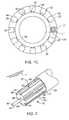
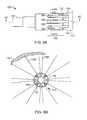
- FIGS. 1 (A), (B) and (C)are elevational views looking at the proximal end of an elongated housing of the present invention adapted to support a plurality of fibers;
- FIG. 2is a perspective view of the distal end of an elongated probe having a central delivery fiber and a plurality of return fibers spaced longitudinally therearound;
- FIG. 3is a perspective view of a further embodiment of the present invention showing an elongated probe having a central lumen and a plurality of alignment grooves spaced therearound;
- FIG. 4Ais a perspective view of an elongated probe with a central bore therethrough and a segment of fiber alignment grooves spaced adjacent a conical distalmost end of the probe;
- FIG. 4Bis a sectional view of the housing shown in FIG. 4A ;
- FIG. 4Cis a view similar to 4 B in a further embodiment thereof.
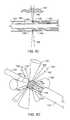
- FIG. 5Ais a perspective view of an elongated probe with alignment grooves therein;
- FIG. 5Bis a view similar to FIG. 5A in a different embodiment thereof;
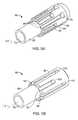
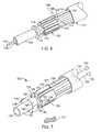
- FIG. 6is a perspective view of an extruded central lumen for an elongated probe with alignment grooves and light signal fibers in a further embodiment thereof;
- FIG. 7is a view similar to FIG. 6 with an alignment groove arrangement in a different embodiment thereof;
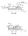
- FIG. 8Ais a side elevational view of the distalend of an elongated probe with alignment grooves therein in a yet further embodiment thereof;
- FIG. 8Bis a view taken along the lines 8 B— 8 B from FIG. 8A ;
- FIG. 8Cis a view taken along the lines 8 C— 8 C of FIG. 8A ;
- FIG. 8Dis a perspective view of the elongated probe showing representations of the light energy signals emitted and received therefrom.
- the first preferred embodiments of the present inventionwhich comprises an elongated generally cylindrically shaped housing 20 having a first or distal 22 , and a second or proximal end 24 .
- the housing 20in a first preferred embodiments have a central bore 26 extending axially therethrough, which may be characterized as a lumen for receiving other elongated devices such as a guidewire or signal carrying members such as fibers or waveguides.
- the housing 20has an outer peripheral surface 28 having a plurality of spaced apart, parallel, longitudinally directed alignment grooves 30 thereon, extending only axially along a central portion of the axial length of the housing 20 .
- FIG. 1 (A)discloses eight such grooves 30
- FIG. 1 (B)disclosing ten such grooves 30
- FIG. 1 (C)disclosing twelve such fiber supporting grooves 30 .
- a step-like ledge or shoulder 32may be arranged transversely with respect to the longitudinal axis “L” of the alignment grooves 30 to act as an abutment or stop for each flexible light signal bearing fiber “F” disposed within the respective alignment grooves 30 .
- An enlarged annular flange 34is disposed longitudinally adjacent the distalmost end of the alignment grooves 30 in this preferred embodiment, adjacent the distalmost end 22 of the probe housing 20 .
- the flange 34may have a sloped reflective surface 36 thereon for re-directing light energy rays from and to the light signal carrying fibers “F”, as will be disclosed in further detail hereinbelow.
- the ledges or shoulders 32 arranged within the trough of the alignment grooves 30may be aligned in a common radial plane or aligned in a number of parallel, spaced apart, radially directed planes, with respect to the longitudinal axis of the housing 20 , as will also be disclosed hereinbelow.
- the ledges or shoulders 32may be of varying radial heights, as shown in FIG. 1 (C) in order to adjust to certain fiber “F” dimensions, and may be angled so as to effect slight radial displacement of the tips of each fiber “F” from the radially inner surface of the respective annular groove 30 in which it is disposed.
- FIG. 2A further embodiment of the generally cylindrically shaped housing 20 comprising the elongated probe is shown in FIG. 2 , which housing 20 includes a central bore or lumen 40 through which a light signal delivery fiber 42 may be stationarily positioned or alternatively, it may be longitudinally adjustably disposed.
- the delivery fiber 42would preferably have a polished conical tip 44 on its distalmost end.
- the elongated housing 20 in this embodimentwould have the plurality of parallel longitudinally directed alignment grooves 46 circumferentially spaced apart about its periphery, each of the alignment grooves 46 having a longitudinally adjustable return light signal bearing fiber 48 disposed therein.
- Each of the return fibers 48would have a polished face 50 arranged at an angle with respect to its own longitudinal axis “L 1 ”.
- the polished face 50would function as a reflective surface for incoming energy rays “E” to be reflected in a return path longitudinally within the return fibers 42 from a tissue “T”.
- the probe or elongated housing 20may be longitudinally displaceable within an outermost catheter sheath 52 , which sheath 52 would be advanced within a mammalian body for analysis and/or treatment by light energy waves with a proper analysis and/or treatment source, not shown for simplicity of the figures.
- FIG. 3A further embodiment of the present invention is shown in FIG. 3 , which contemplates a generally cylindrically shaped housing 20 having a central bore 54 which functions as a lumen for a guide wire or further energy bearing fiber 56 .
- the outer surface of the elongated probe or housing 20has the aforementioned plurality of elongated, circumferentially disposed alignment channels or grooves 58 fabricated (as by extrusion, molding or machining) therein, with each of the elongated grooves 58 having a light bearing fiber 60 therein.
- Alternating circumferentially arranged light bearing fibers 60 in this embodimentmay be a light delivery fiber 60 D and a collection or return signal fiber 60 R.
- the delivery signal fibers 60 D and the return signal fibers 60 Rmay each have a polished distalmost end face 62 thereon at an angle of about 45 degrees with respect to its longitudinal axis “L 3 ” thereof. It is further contemplated that each individual light delivery or light return signal fiber 60 D or 60 R may be longitudinally displaceable within their respective alignment grooves 58 for adjustment of the desired analysis and/or treatment to mammalian body tissue being treated.
- FIGS. 4 (A), 4 (B) and 4 (C)present another preferred embodiment of the present invention which contemplates the elongated generally cylindrically shaped housing probe 20 having a proximal portion 64 of reduced diameter with respect to the outer surface 66 of a central portion 68 of the housing probe 20 , the central portion 68 having a plurality of generally parallel, circumferentially spaced-apart, light energy bearing fiber alignment grooves 70 arranged peripherally therearound, and the housing probe 20 also having a distalmost nose portion 72 .
- the distalmost nose portion 72preferably has a sloped or tapered forward end 74 and an inclined or tapered rearward edge 76 .
- the tapered rearward edge 76of angular configuration as may be seen in FIG.
- a light signal carrying fiber 78would be arranged within each of the alignment grooves 70 as may be seen in FIG. 4 (B).
- the signal fibers 78have a distalmost end face 80 through which light energy signals “E 4 ” would be delivered and/or received by bouncing off of the reflective angular surface on the tapered rearward edge 76 of the nose portion 72 of the elongated housing 20 .
- the energy “E 4 ”may be delivered from and/or returned to a proper energy generator and analysis apparatus 79 , through a proper circuit 81 , which provides a source and analysis of energy signals for analysis/ diagnosis and treatment of mammalian tissue “T 4 ”, exemplary for all the embodiments of the present invention.
- the nose portion 72 of the elongated housing 20 distal of the alignment grooves 70may also be longitudinally displaceable as shown by arrow “A” along the longitudinal axis “L 4 ” of the elongated housing 20 .
- the rearward edge 76may consist of a reflective surface 77 which may be somewhat arcuate or segmented in cross section or have angled reflective portions thereon, as represented in FIG. 4 (C), thus to effect change therein by angular displacement of energy signals “E 4 ” being delivered to or received from tissue adjacent to the elongated probe housing 20 in the distal end of a catheter in which the tissue analysis/treatment is being undertaken during the longitudinal adjustment of the nose portion 72 .
- FIGS. 5 (A) and 5 (B)shown further embodiments of the present invention which contemplates an elongated generally cylindrically shaped housing 86 having a proximalmost end 88 of reduced diameter compared with the distal half 90 of the housing 86 .
- a central bore 92extends through the elongated housing 86 and out the distalmost end thereof 90 .
- the distalmost half portion 90 of the elongated housing 86has a plurality of generally parallel, spaced apart circumferentially disposed alignment grooves 94 fabricated therein.
- the alignment grooves 94are parallel with respect to the longitudinal axis “L 5 ” of the elongated housing 86 .
- the axial length of the respective alignment grooves 94are dissimilar, as is shown in FIGS. 5 (A) and 5 (B). There is a longitudinal separation between the distalmost ends of alternate alignment grooves 94 to permit a spread in the collection and/or delivery of energy with respect to any fibers (not shown in these figures) disposed therewithin.
- the distalmost end of each alignment groove 94 in the elongated housing 86 of this embodimenthas an angled polished mirror face 96 therein.
- the arcuate segment defining the mirror face 96 for each alignment grooveis preferably arcuately (circumferentially) larger than the arcuate (circumferential) width of each respective alignment groove 94 , as shown in FIG. 5 (A).
- Such longitudinal difference between adjacent signal carrying fibers as represented by the longitudinal difference in the axial lengths of the grooves 94 fiberspermits greater paths of analyses of body tissue being examined or treated.
- mirrors 100 on the distal end of the alignment grooves 94being the same arcuate (width) dimension as the respective alignment grooves 94 in which they sit, as is shown in FIG. 5 (B).
- FIG. 6shows yet another embodiment contemplated for the elongated probe housing 102 for the distal end of a catheter 103 which may comprise a single elongated extrusion 104 having a bore 106 extending longitudinally therethrough.
- the extrusion's distal enddefines the probe component 102 in this example.
- the housing probe 102 in this componentalso includes a plurality of axially aligned alignment grooves 108 exterior to the extrusion 104 , the alignment grooves 108 each carrying a fiber 110 spaced therewithin.
- a conical reflector 112is spaced distal of the distal end of the fiber alignment grooves 108 and the fibers 110 therewithin.
- a ball tip 114may be fused onto the distal end of the delivery fibers 110 and/or the return fibers 110 seated within the alignment grooves 108 of the housing 102 of this probe 102 .
- the ball tips 114preferably provide a lens arrangement or alternatively a reflective arrangement for an enlarged variation of beam spread for light energy being delivered or returned through their respective fibers 110 .
- the central lumen 106 within the extrusion 104may carry a guide wire 116 for delivery of the probe 102 within a body conduit, or the central lumen 106 may also include one or more energy delivery fibers, not shown for clarity, for delivering light signal energy to that probe location.
- FIG. 7shows yet another preferred embodiment of the present invention which contemplates an elongated probe 120 comprised of an extruded elongated housing 122 having a plurality of external and internal alignment grooves 124 and 128 fabricated peripherally and circumferentially therein.
- the alignment grooves 124 in this embodimentare arranged both adjacent the external peripheral surface 126 of the housing 122 each carrying a signal fiber 130 , and also alternatively on the inner surface 127 of the annularly shaped housing 122 so as to permit a greater number of fibers 130 or a greater fiber density to permit alterations or changing in fiber spacing for greater control of fibers 130 and their respective beams of light energy which they deliver or receive.
- the annular housing 122 into which the alignment grooves 124 and 128 are fabricatedmates about the elongated extrusion 122 having a central bore 136 therethrough.
- An annular array of lensed prisms 138 in this embodimentare arranged distally of the annular alignment groove housing 120 .
- Each respective lensed prism 140 in the annular array of multiple lensed prisms 138may function with and direct an energy signal to and from more than one adjacent signal fiber 130 .
- Such an annular array of lensed prisms 138would permit overlapping energy signals to be sent and/or received through adjacent signal fibers 130 .
- Each of the fibers 130have their proximal ends in communication through a proper circuit 135 with an energy generating apparatus 133 and an energy receiving and analysis apparatus 137 in communication through a proper circuit 139 , for analysis of light energy signals that have been sent and reflected through various body tissues “T 7 ” external of the catheter probe 120 and received through the appropriate return fibers for computer analysis and reporting.
- FIGS. 8 (A), 8 ( 13 ), 8 (C) and 8 (D)which embodiment contemplates an elongated housing 150 disposed about a central extrusion 152 having an inner bore 154 therewith, and placed in an energy beam transparent catheter sheath 155 .
- the elongated housing 150has a distalmost end which is situated adjacent the distal end of the extruded core 152 .
- the elongated housing 150has a proximalmost half end portion 156 with a plurality of parallel, longitudinally directed, circumferentially disposed alignment grooves 158 therein.
- the alignment grooves 158 in this embodimenthave a distal end 160 which define a reflective surface 162 fabricated on the housing portion 156 thereof.
- the respective reflective distalmost end portions 160 of the alignment grooves 158are arranged at a different angle with respect to the longitudinal axes “L 8 ” of the respective signal fibers 164 disposed within those alignment grooves 158 .
- the reflective surfaces 162therefore, may deliver a wider beam of light energy “D 8 ” and may return a narrower beam of light energy “R 8 ” reflected from the radially adjacent tissue “T 8 ” within which the elongated probe is placed, as represented in FIGS. 8 (B), 8 (C) and 8 (D).
- NAnumerical aperture
- Beam redirecting memberssuch as mirrors, lenses, dielectric mirrors, diffractive optical elements may have a separation of about 0.1 mm to about 2 mm.
- a unique elongated probearrangeable within the distalmost end of a mammalian body tissue engaging catheter, which elongated probe carries a plurality of energy delivery members such as for example optical fibers or optical waveguides and energy collecting members such as optical fibers or optical waveguides or the like.
- the collector membersare preferably arranged in annular array about a central extrusion.
- the central extrusionmay contain a bore or lumen for a further fiber or guidewire to facilitate entrance within a body lumen.
- the spectrum of energy delivered and received by the annular array of fibersmay run from the ultrasound to the ultraviolet or beyond.
- each light bearing membersuch as a fiber may function as both a light delivery member (fiber etc) and a light collection member (fiber etc).
Landscapes
- Health & Medical Sciences (AREA)
- Life Sciences & Earth Sciences (AREA)
- Surgery (AREA)
- Physics & Mathematics (AREA)
- Biomedical Technology (AREA)
- Molecular Biology (AREA)
- Veterinary Medicine (AREA)
- Public Health (AREA)
- Nuclear Medicine, Radiotherapy & Molecular Imaging (AREA)
- Engineering & Computer Science (AREA)
- General Health & Medical Sciences (AREA)
- Heart & Thoracic Surgery (AREA)
- Medical Informatics (AREA)
- Optics & Photonics (AREA)
- Animal Behavior & Ethology (AREA)
- Biophysics (AREA)
- Radiology & Medical Imaging (AREA)
- Pathology (AREA)
- Electromagnetism (AREA)
- Otolaryngology (AREA)
- Investigating Or Analysing Materials By Optical Means (AREA)
- Endoscopes (AREA)
Abstract
Description
Claims (43)
Priority Applications (2)
| Application Number | Priority Date | Filing Date | Title |
|---|---|---|---|
| US10/037,307US6873868B2 (en) | 2001-12-31 | 2001-12-31 | Multi-fiber catheter probe arrangement for tissue analysis or treatment |
| PCT/US2003/006801WO2004078045A1 (en) | 2001-12-31 | 2003-03-05 | Multi-fiber catheter probe arrangement for tissue analysis or treatment |
Applications Claiming Priority (2)
| Application Number | Priority Date | Filing Date | Title |
|---|---|---|---|
| US10/037,307US6873868B2 (en) | 2001-12-31 | 2001-12-31 | Multi-fiber catheter probe arrangement for tissue analysis or treatment |
| PCT/US2003/006801WO2004078045A1 (en) | 2001-12-31 | 2003-03-05 | Multi-fiber catheter probe arrangement for tissue analysis or treatment |
Publications (2)
| Publication Number | Publication Date |
|---|---|
| US20030125719A1 US20030125719A1 (en) | 2003-07-03 |
| US6873868B2true US6873868B2 (en) | 2005-03-29 |
Family
ID=33455768
Family Applications (1)
| Application Number | Title | Priority Date | Filing Date |
|---|---|---|---|
| US10/037,307Expired - LifetimeUS6873868B2 (en) | 2001-12-31 | 2001-12-31 | Multi-fiber catheter probe arrangement for tissue analysis or treatment |
Country Status (2)
| Country | Link |
|---|---|
| US (1) | US6873868B2 (en) |
| WO (1) | WO2004078045A1 (en) |
Cited By (31)
| Publication number | Priority date | Publication date | Assignee | Title |
|---|---|---|---|---|
| US20050124918A1 (en)* | 2003-12-05 | 2005-06-09 | Scimed Life Systems, Inc. | Guide catheter with removable support |
| US20050165314A1 (en)* | 2004-01-27 | 2005-07-28 | Fujinon Corporation | Electronic scan type ultrasound diagnostic instrument |
| US20060058679A1 (en)* | 2004-08-20 | 2006-03-16 | Fuji Photo Film Co., Ltd. | Ultrasonic endoscope and ultrasonic endoscopic apparatus |
| US20060293644A1 (en)* | 2005-06-21 | 2006-12-28 | Donald Umstadter | System and methods for laser-generated ionizing radiation |
| US20070078500A1 (en)* | 2005-09-30 | 2007-04-05 | Cornova, Inc. | Systems and methods for analysis and treatment of a body lumen |
| US20070219451A1 (en)* | 2006-03-03 | 2007-09-20 | John Kula | Optical Imaging Balloon Catheters |
| US20070270717A1 (en)* | 2005-09-30 | 2007-11-22 | Cornova, Inc. | Multi-faceted optical reflector |
| US20070291275A1 (en)* | 2006-06-16 | 2007-12-20 | Prescient Medical, Inc. | Side-viewing optical acoustic sensors and their use in intravascular diagnostic probes |
| US20080045842A1 (en)* | 2006-07-21 | 2008-02-21 | Prescient Medical, Inc. | Conformable tissue contact catheter |
| US20080051629A1 (en)* | 2003-07-29 | 2008-02-28 | Akira Sugiyama | Internal Treatment Apparatus for a Patient and an Internal Treatment System for a Patient |
| US20080129993A1 (en)* | 2006-10-23 | 2008-06-05 | Brennan James F | Windowless fiber optic raman spectroscopy probes |
| US20080304074A1 (en)* | 2007-06-08 | 2008-12-11 | Brennan Iii James F | Optical catheter configurations combining raman spectroscopy with optical fiber-based low coherence reflectometry |
| US20090024040A1 (en)* | 2007-07-20 | 2009-01-22 | Prescient Medical, Inc. | Wall-Contacting Intravascular Ultrasound Probe Catheters |
| US20090076395A1 (en)* | 2007-09-19 | 2009-03-19 | Prescient Medical, Inc. | Optimized intravascular ultrasound probe catherers |
| US20090175576A1 (en)* | 2008-01-08 | 2009-07-09 | Cornova, Inc. | Shaped fiber ends and methods of making same |
| US20090187108A1 (en)* | 2006-09-29 | 2009-07-23 | Cornova, Inc. | Systems and methods for analysis and treatment of a body lumen |
| US20090231578A1 (en)* | 2007-05-17 | 2009-09-17 | Jian Ling | Multi-channel fiber optic spectroscopy systems employing integrated optics modules |
| US20100094109A1 (en)* | 2008-10-15 | 2010-04-15 | Cornova, Inc. | Systems and methods for analysis and treatment of an occluded body lumen |
| US20100113906A1 (en)* | 2008-11-06 | 2010-05-06 | Prescient Medical, Inc. | Hybrid basket catheters |
| DE102008058148A1 (en)* | 2008-11-20 | 2010-05-27 | Vimecon Gmbh | laser applicator |
| US20100174196A1 (en)* | 2007-06-21 | 2010-07-08 | Cornova, Inc. | Systems and methods for guiding the analysis and treatment of a body lumen |
| US20100286531A1 (en)* | 2005-09-30 | 2010-11-11 | Cornova, Inc. | Systems and methods for analysis and treatment of a body lumen |
| US20110028788A1 (en)* | 2008-03-24 | 2011-02-03 | The Regents Of The University Of Michigan | Non-Contact Infrared Fiber-Optic Device for Monitoring Esophageal Temperature to Prevent Thermal Injury During Radiofrequency Catheter Ablation or Cryoablation |
| US20120078052A1 (en)* | 2006-02-07 | 2012-03-29 | Boston Scientific Scimed, Inc. | Medical device light source |
| US20130287360A1 (en)* | 2012-04-26 | 2013-10-31 | Hubert Blair Beamon | Fiber optic enclosures employing clamping assemblies for strain relief of cables, and related assemblies and methods |
| US8755663B2 (en) | 2010-10-28 | 2014-06-17 | Corning Cable Systems Llc | Impact resistant fiber optic enclosures and related methods |
| US20140364699A1 (en)* | 2011-09-23 | 2014-12-11 | Alcon Research, Ltd. | Ophthalmic endoilluminators with directed light |
| US8958867B2 (en) | 2011-08-29 | 2015-02-17 | Infraredx, Inc. | Detection of lipid core plaque cap thickness |
| US9069151B2 (en) | 2011-10-26 | 2015-06-30 | Corning Cable Systems Llc | Composite cable breakout assembly |
| US10070793B2 (en) | 2010-11-27 | 2018-09-11 | Securus Medical Group, Inc. | Ablation and temperature measurement devices |
| US10776654B2 (en) | 2015-03-10 | 2020-09-15 | Infraredx, Inc. | Assessment of lipid core plaque integrity |
Families Citing this family (92)
| Publication number | Priority date | Publication date | Assignee | Title |
|---|---|---|---|---|
| EP0979635A2 (en) | 1998-08-12 | 2000-02-16 | Origin Medsystems, Inc. | Tissue dissector apparatus |
| US6558313B1 (en)* | 2000-11-17 | 2003-05-06 | Embro Corporation | Vein harvesting system and method |
| US20040199052A1 (en) | 2003-04-01 | 2004-10-07 | Scimed Life Systems, Inc. | Endoscopic imaging system |
| US20040236231A1 (en)* | 2003-05-23 | 2004-11-25 | Embro Corporation | Light catheter for illuminating tissue structures |
| US20050137459A1 (en)* | 2003-12-17 | 2005-06-23 | Scimed Life Systems, Inc. | Medical device with OLED illumination light source |
| DE102004026619B4 (en)* | 2004-06-01 | 2007-06-06 | Siemens Ag | Catheter with improved illumination of the target area |
| GB0426993D0 (en) | 2004-12-09 | 2005-01-12 | Council Cent Lab Res Councils | Apparatus for depth-selective raman spectroscopy |
| WO2006076759A1 (en)* | 2005-01-21 | 2006-07-27 | Optiscan Pty Ltd | Fibre bundle for contact endomicroscopy |
| US7515957B2 (en)* | 2005-06-23 | 2009-04-07 | Medtronic Vascular, Inc. | Catheter-based, dual balloon photopolymerization system |
| US20090093403A1 (en) | 2007-03-01 | 2009-04-09 | Feng Zhang | Systems, methods and compositions for optical stimulation of target cells |
| US8926959B2 (en)* | 2005-07-22 | 2015-01-06 | The Board Of Trustees Of The Leland Stanford Junior University | System for optical stimulation of target cells |
| US9274099B2 (en) | 2005-07-22 | 2016-03-01 | The Board Of Trustees Of The Leland Stanford Junior University | Screening test drugs to identify their effects on cell membrane voltage-gated ion channel |
| US10052497B2 (en) | 2005-07-22 | 2018-08-21 | The Board Of Trustees Of The Leland Stanford Junior University | System for optical stimulation of target cells |
| EP2465925A1 (en) | 2005-07-22 | 2012-06-20 | The Board Of Trustees Of The Leland | Light-activated cation channel and uses thereof |
| US9238150B2 (en) | 2005-07-22 | 2016-01-19 | The Board Of Trustees Of The Leland Stanford Junior University | Optical tissue interface method and apparatus for stimulating cells |
| SE531740C2 (en)* | 2005-11-21 | 2009-07-28 | Samba Sensors Ab | Device for measuring physical quantity in an anatomical organ |
| GB0606891D0 (en) | 2006-04-05 | 2006-05-17 | Council Cent Lab Res Councils | Raman Analysis Of Pharmaceutical Tablets |
| US20080108867A1 (en)* | 2005-12-22 | 2008-05-08 | Gan Zhou | Devices and Methods for Ultrasonic Imaging and Ablation |
| US9770230B2 (en) | 2006-06-01 | 2017-09-26 | Maquet Cardiovascular Llc | Endoscopic vessel harvesting system components |
| US8398692B2 (en) | 2007-01-10 | 2013-03-19 | The Board Of Trustees Of The Leland Stanford Junior University | System for optical stimulation of target cells |
| KR20090107536A (en) | 2007-01-22 | 2009-10-13 | 캘리포니아 인스티튜트 오브 테크놀로지 | Method for Quantitative 3-D Imaging |
| US8089635B2 (en) | 2007-01-22 | 2012-01-03 | California Institute Of Technology | Method and system for fast three-dimensional imaging using defocusing and feature recognition |
| US8401609B2 (en) | 2007-02-14 | 2013-03-19 | The Board Of Trustees Of The Leland Stanford Junior University | System, method and applications involving identification of biological circuits such as neurological characteristics |
| US9018724B2 (en)* | 2007-03-28 | 2015-04-28 | Advancedmems Llp | Method of producing optical MEMS |
| AU2008244494B2 (en) | 2007-04-23 | 2010-10-21 | California Institute Of Technology | Single-lens 3-D imaging device using a polarization-coded aperture mask combined with a polarization-sensitive sensor |
| US8226548B2 (en)* | 2007-07-07 | 2012-07-24 | Cannuflow, Inc. | Rigid arthroscope system |
| US10434327B2 (en) | 2007-10-31 | 2019-10-08 | The Board Of Trustees Of The Leland Stanford Junior University | Implantable optical stimulators |
| US10035027B2 (en)* | 2007-10-31 | 2018-07-31 | The Board Of Trustees Of The Leland Stanford Junior University | Device and method for ultrasonic neuromodulation via stereotactic frame based technique |
| US8514268B2 (en)* | 2008-01-22 | 2013-08-20 | California Institute Of Technology | Method and device for high-resolution three-dimensional imaging which obtains camera pose using defocusing |
| EP3165534B1 (en) | 2008-04-23 | 2018-09-26 | The Board of Trustees of The Leland Stanford Junior University | Systems, methods and compositions for optical stimulation of target cells |
| CN102076866A (en)* | 2008-05-29 | 2011-05-25 | 利兰·斯坦福青年大学托管委员会 | Cell lines, systems and methods for optically controlling second messengers |
| SG191604A1 (en)* | 2008-06-17 | 2013-07-31 | Univ Leland Stanford Junior | Apparatus and methods for controlling cellular development |
| WO2009155371A1 (en) | 2008-06-17 | 2009-12-23 | The Board Of Trustees Of The Leland Stanford Junior University | Methods, systems and devices for optical stimulation of target cells using an optical transmission element |
| US9101759B2 (en) | 2008-07-08 | 2015-08-11 | The Board Of Trustees Of The Leland Stanford Junior University | Materials and approaches for optical stimulation of the peripheral nervous system |
| ITFI20080129A1 (en)* | 2008-07-14 | 2010-01-15 | El En Spa | "MULTIFIBRE LASER DISPENSER DEVICE FOR PERCUTANEOUS OR SIMILAR TREATMENTS AND APPARATUS INCLUDING THIS DISPENSER" |
| US20100094138A1 (en)* | 2008-07-25 | 2010-04-15 | Morteza Gharib | Imaging catheter using laser profile for plaque depth measurement |
| NZ602416A (en) | 2008-11-14 | 2014-08-29 | Univ Leland Stanford Junior | Optically-based stimulation of target cells and modifications thereto |
| US8773507B2 (en)* | 2009-08-11 | 2014-07-08 | California Institute Of Technology | Defocusing feature matching system to measure camera pose with interchangeable lens cameras |
| US8773514B2 (en)* | 2009-08-27 | 2014-07-08 | California Institute Of Technology | Accurate 3D object reconstruction using a handheld device with a projected light pattern |
| US9089351B2 (en) | 2010-02-12 | 2015-07-28 | Intuitive Surgical Operations, Inc. | Sheath for surgical instrument |
| US10376331B2 (en) | 2010-02-12 | 2019-08-13 | Intuitive Surgical Operations, Inc. | Sheaths for jointed instruments |
| ES2676274T3 (en) | 2010-03-17 | 2018-07-18 | The Board Of Trustees Of The Leland Stanford Junior University | Light sensitive molecules that allow the passage of ions |
| US9138284B2 (en)* | 2010-07-09 | 2015-09-22 | Intuitive Surgical Operations, Inc. | Electrosurgical tool cover |
| JP6007178B2 (en) | 2010-09-03 | 2016-10-12 | カリフォルニア インスティテュート オブ テクノロジー | 3D imaging system |
| JP6276591B2 (en) | 2010-11-05 | 2018-02-07 | ザ ボード オブ トラスティーズ オブ ザ レランド スタンフォード ジュニア ユニバーシティー | Photo-activated chimeric opsin and method of use thereof |
| EP2635109A4 (en) | 2010-11-05 | 2014-03-19 | Univ Leland Stanford Junior | OPTICALLY CONTROLLED CNS DYSFUNCTION |
| EP2635295B1 (en) | 2010-11-05 | 2017-12-20 | The Board of Trustees of the Leland Stanford Junior University | Control and characterization of memory function |
| EP2635341B1 (en) | 2010-11-05 | 2018-08-08 | The Board of Trustees of the Leland Stanford Junior University | Upconversion of light for use in optogenetic methods |
| EP2635346B1 (en) | 2010-11-05 | 2017-03-29 | The Board of Trustees of the Leland Stanford Junior University | Optogenetic control of reward-related behaviors |
| WO2012061744A2 (en) | 2010-11-05 | 2012-05-10 | The Board Of Trustees Of The Leland Stanford Junior University | Stabilized step function opsin proteins and methods of using the same |
| US8696722B2 (en) | 2010-11-22 | 2014-04-15 | The Board Of Trustees Of The Leland Stanford Junior University | Optogenetic magnetic resonance imaging |
| EP2677961B1 (en) | 2011-02-24 | 2024-12-11 | Eximo Medical Ltd. | Hybrid catheter for vascular intervention |
| AU2012312066C1 (en) | 2011-09-22 | 2016-06-16 | 460Medical, Inc. | Systems and methods for visualizing ablated tissue |
| JP6406581B2 (en) | 2011-12-16 | 2018-10-17 | ザ ボード オブ トラスティーズ オブ ザ レランド スタンフォード ジュニア ユニバーシティー | Opsin polypeptides and uses thereof |
| WO2013103410A1 (en) | 2012-01-05 | 2013-07-11 | California Institute Of Technology | Imaging surround systems for touch-free display control |
| US20140024701A1 (en) | 2012-02-21 | 2014-01-23 | Circuit Therapeutics, Inc. | Compositions and Methods for Treating Neurogenic Disorders of the Pelvic Floor |
| WO2013177577A2 (en) | 2012-05-25 | 2013-11-28 | Eberle Michael J | Optical fiber pressure sensor |
| US9530213B2 (en) | 2013-01-02 | 2016-12-27 | California Institute Of Technology | Single-sensor system for extracting depth information from image blur |
| EP2968997B1 (en) | 2013-03-15 | 2019-06-26 | The Board of Trustees of the Leland Stanford Junior University | Optogenetic control of behavioral state |
| US9636380B2 (en) | 2013-03-15 | 2017-05-02 | The Board Of Trustees Of The Leland Stanford Junior University | Optogenetic control of inputs to the ventral tegmental area |
| CN105431046B (en) | 2013-04-29 | 2020-04-17 | 小利兰·斯坦福大学托管委员会 | Devices, systems, and methods for optogenetic modulation of action potentials in target cells |
| EP3033427A4 (en) | 2013-08-14 | 2017-05-31 | The Board Of Trustees Of The University Of the Leland Stanford Junior University | Compositions and methods for controlling pain |
| WO2015051003A1 (en) | 2013-10-04 | 2015-04-09 | Vascular Imaging Corporation | Imaging techniques using an imaging guidewire |
| JP6737705B2 (en) | 2013-11-14 | 2020-08-12 | ザ・ジョージ・ワシントン・ユニバーシティThe George Washingtonuniversity | Method of operating system for determining depth of injury site and system for generating images of heart tissue |
| US10537255B2 (en) | 2013-11-21 | 2020-01-21 | Phyzhon Health Inc. | Optical fiber pressure sensor |
| US10537226B2 (en)* | 2013-12-23 | 2020-01-21 | California Institute Of Technology | Rotational scanning endoscope |
| US20150196361A1 (en)* | 2014-01-14 | 2015-07-16 | Lumenis Ltd. | Apparatus and method for fragmenting and aspirating materials from a body lumen |
| EP3139989A4 (en)* | 2014-05-08 | 2017-05-17 | Eximo Medical Ltd. | Methods for deflecting catheters |
| WO2016145259A1 (en)* | 2015-03-10 | 2016-09-15 | Leland Stanford Junior University | Devices and methods for analysis of tissues |
| US10568516B2 (en) | 2015-06-22 | 2020-02-25 | The Board Of Trustees Of The Leland Stanford Junior University | Methods and devices for imaging and/or optogenetic control of light-responsive neurons |
| US10779904B2 (en) | 2015-07-19 | 2020-09-22 | 460Medical, Inc. | Systems and methods for lesion formation and assessment |
| WO2017132165A1 (en) | 2016-01-25 | 2017-08-03 | California Institute Of Technology | Non-invasive measurement of intraocular pressure |
| WO2017139630A1 (en)* | 2016-02-12 | 2017-08-17 | Ipg Photonics Corporation | Laser alignment apparatus and system for alignment of output fiber of a fiber laser |
| CN109414292A (en)* | 2016-05-05 | 2019-03-01 | 爱克斯莫医疗有限公司 | Device and method for cutting off and/or melting unwanted tissue |
| CN110337277A (en)* | 2017-02-28 | 2019-10-15 | 诺华股份有限公司 | Multi fiber multipoint mode laser microprobe with the separation of articulated type beam |
| US11294165B2 (en) | 2017-03-30 | 2022-04-05 | The Board Of Trustees Of The Leland Stanford Junior University | Modular, electro-optical device for increasing the imaging field of view using time-sequential capture |
| WO2018220488A1 (en) | 2017-05-30 | 2018-12-06 | Novartis Ag | Multi-fiber multi-spot laser probe with articulating beam separation |
| WO2019075706A1 (en)* | 2017-10-20 | 2019-04-25 | 周震华 | Distal tip portion having irregular cylindrical structure, endoscope, and method for manufacturing same |
| US12402946B2 (en) | 2019-06-19 | 2025-09-02 | Boston Scientific Scimed, Inc. | Breakdown of laser pulse energy for breakup of vascular calcium |
| US12280223B2 (en) | 2019-06-26 | 2025-04-22 | Boston Scientific Scimed, Inc. | Focusing element for plasma system to disrupt vascular lesions |
| US12102384B2 (en) | 2019-11-13 | 2024-10-01 | Bolt Medical, Inc. | Dynamic intravascular lithotripsy device with movable energy guide |
| US12274497B2 (en) | 2019-12-18 | 2025-04-15 | Bolt Medical, Inc. | Multiplexer for laser-driven intravascular lithotripsy device |
| EP4087511A4 (en) | 2020-01-08 | 2024-02-14 | 460Medical, Inc. | Systems and methods for optical interrogation of ablation lesions |
| US20210290286A1 (en) | 2020-03-18 | 2021-09-23 | Bolt Medical, Inc. | Optical analyzer assembly and method for intravascular lithotripsy device |
| US12295654B2 (en) | 2020-06-03 | 2025-05-13 | Boston Scientific Scimed, Inc. | System and method for maintaining balloon integrity within intravascular lithotripsy device with plasma generator |
| US12207870B2 (en) | 2020-06-15 | 2025-01-28 | Boston Scientific Scimed, Inc. | Spectroscopic tissue identification for balloon intravascular lithotripsy guidance |
| US12376904B1 (en)* | 2020-09-08 | 2025-08-05 | Angiodynamics, Inc. | Dynamic laser stabilization and calibration system |
| US12016610B2 (en) | 2020-12-11 | 2024-06-25 | Bolt Medical, Inc. | Catheter system for valvuloplasty procedure |
| EP4277548B1 (en) | 2021-01-12 | 2025-06-04 | Bolt Medical, Inc. | Balloon assembly for valvuloplasty catheter system |
| CN113633372B (en)* | 2021-10-18 | 2022-03-01 | 北京智愈医疗科技有限公司 | Ablation tool array device for tissue ablation and control method thereof |
| US11839391B2 (en)* | 2021-12-14 | 2023-12-12 | Bolt Medical, Inc. | Optical emitter housing assembly for intravascular lithotripsy device |
| US12038322B2 (en) | 2022-06-21 | 2024-07-16 | Eximo Medical Ltd. | Devices and methods for testing ablation systems |
Citations (31)
| Publication number | Priority date | Publication date | Assignee | Title |
|---|---|---|---|---|
| US3847483A (en) | 1972-02-01 | 1974-11-12 | R Shaw | Optical oximeter apparatus and method |
| US4672961A (en)* | 1986-05-19 | 1987-06-16 | Davies David H | Retrolasing catheter and method |
| US4832023A (en)* | 1987-06-03 | 1989-05-23 | Mcm Laboratories, Inc. | Method and apparatus for reducing blockage in body channels |
| US4850351A (en)* | 1985-05-22 | 1989-07-25 | C. R. Bard, Inc. | Wire guided laser catheter |
| US4917097A (en)* | 1987-10-27 | 1990-04-17 | Endosonics Corporation | Apparatus and method for imaging small cavities |
| US4950266A (en)* | 1985-07-31 | 1990-08-21 | C. R. Bard, Inc. | Infrared laser catheter system |
| US4967745A (en)* | 1987-04-10 | 1990-11-06 | Massachusetts Institute Of Technology | Multi-fiber plug for a laser catheter |
| US5081993A (en)* | 1987-11-11 | 1992-01-21 | Circulation Research Limited | Methods and apparatus for the examination and treatment of internal organs |
| US5242438A (en)* | 1991-04-22 | 1993-09-07 | Trimedyne, Inc. | Method and apparatus for treating a body site with laterally directed laser radiation |
| US5405318A (en)* | 1992-05-05 | 1995-04-11 | Baxter International Inc. | Ultra-sound catheter for removing obstructions from tubular anatomical structures such as blood vessels |
| US5456259A (en)* | 1991-07-30 | 1995-10-10 | Intravascular Research Limited | Ultrasonic transducer arrangement and catheter |
| US5465726A (en)* | 1992-01-30 | 1995-11-14 | Intravascular Research Limited | Ultrasound imaging and catheters for use therein |
| US5470330A (en)* | 1984-12-07 | 1995-11-28 | Advanced Interventional Systems, Inc. | Guidance and delivery system for high-energy pulsed laser light |
| US5693043A (en) | 1985-03-22 | 1997-12-02 | Massachusetts Institute Of Technology | Catheter for laser angiosurgery |
| US5700243A (en)* | 1992-10-30 | 1997-12-23 | Pdt Systems, Inc. | Balloon perfusion catheter |
| US5716320A (en)* | 1994-10-31 | 1998-02-10 | Buttermore; William J. | Illuminated intraocular surgical instrument |
| US5730700A (en) | 1992-05-14 | 1998-03-24 | The United States Of America As Represented By The Department Of Health And Human Service | Method for measuring incident light in a body cavity |
| US5827267A (en)* | 1992-02-18 | 1998-10-27 | Angeion Corporation | Cooled multi-fiber medical connector |
| US5830209A (en)* | 1992-02-05 | 1998-11-03 | Angeion Corporation | Multi-fiber laser catheter |
| US5876345A (en)* | 1997-02-27 | 1999-03-02 | Acuson Corporation | Ultrasonic catheter, system and method for two dimensional imaging or three-dimensional reconstruction |
| US5953477A (en)* | 1995-11-20 | 1999-09-14 | Visionex, Inc. | Method and apparatus for improved fiber optic light management |
| US6026316A (en)* | 1997-05-15 | 2000-02-15 | Regents Of The University Of Minnesota | Method and apparatus for use with MR imaging |
| US6156029A (en)* | 1997-11-25 | 2000-12-05 | Eclipse Surgical Technologies, Inc. | Selective treatment of endocardial/myocardial boundary |
| US6270492B1 (en)* | 1994-09-09 | 2001-08-07 | Cardiofocus, Inc. | Phototherapeutic apparatus with diffusive tip assembly |
| US6283921B1 (en)* | 1996-07-11 | 2001-09-04 | Intravascular Research Limited | Ultrasonic visualization and catheters therefor |
| US6321106B1 (en)* | 1996-11-05 | 2001-11-20 | Jerome Lemelson | System and method for treating select tissue in a living being |
| US6416234B1 (en)* | 1995-11-20 | 2002-07-09 | Cirrex, Corp. | Couplers for optical fibers |
| US20020183623A1 (en)* | 2001-05-31 | 2002-12-05 | Jing Tang | Multi-path optical catheter |
| US6511475B1 (en)* | 1997-05-15 | 2003-01-28 | The General Hospital Corporation | Heads for dermatology treatment |
| US6564088B1 (en) | 2000-01-21 | 2003-05-13 | University Of Massachusetts | Probe for localized tissue spectroscopy |
| US20030100824A1 (en)* | 2001-08-23 | 2003-05-29 | Warren William L. | Architecture tool and methods of use |
- 2001
- 2001-12-31USUS10/037,307patent/US6873868B2/ennot_activeExpired - Lifetime
- 2003
- 2003-03-05WOPCT/US2003/006801patent/WO2004078045A1/enactiveApplication Filing
Patent Citations (31)
| Publication number | Priority date | Publication date | Assignee | Title |
|---|---|---|---|---|
| US3847483A (en) | 1972-02-01 | 1974-11-12 | R Shaw | Optical oximeter apparatus and method |
| US5470330A (en)* | 1984-12-07 | 1995-11-28 | Advanced Interventional Systems, Inc. | Guidance and delivery system for high-energy pulsed laser light |
| US5693043A (en) | 1985-03-22 | 1997-12-02 | Massachusetts Institute Of Technology | Catheter for laser angiosurgery |
| US4850351A (en)* | 1985-05-22 | 1989-07-25 | C. R. Bard, Inc. | Wire guided laser catheter |
| US4950266A (en)* | 1985-07-31 | 1990-08-21 | C. R. Bard, Inc. | Infrared laser catheter system |
| US4672961A (en)* | 1986-05-19 | 1987-06-16 | Davies David H | Retrolasing catheter and method |
| US4967745A (en)* | 1987-04-10 | 1990-11-06 | Massachusetts Institute Of Technology | Multi-fiber plug for a laser catheter |
| US4832023A (en)* | 1987-06-03 | 1989-05-23 | Mcm Laboratories, Inc. | Method and apparatus for reducing blockage in body channels |
| US4917097A (en)* | 1987-10-27 | 1990-04-17 | Endosonics Corporation | Apparatus and method for imaging small cavities |
| US5081993A (en)* | 1987-11-11 | 1992-01-21 | Circulation Research Limited | Methods and apparatus for the examination and treatment of internal organs |
| US5242438A (en)* | 1991-04-22 | 1993-09-07 | Trimedyne, Inc. | Method and apparatus for treating a body site with laterally directed laser radiation |
| US5456259A (en)* | 1991-07-30 | 1995-10-10 | Intravascular Research Limited | Ultrasonic transducer arrangement and catheter |
| US5465726A (en)* | 1992-01-30 | 1995-11-14 | Intravascular Research Limited | Ultrasound imaging and catheters for use therein |
| US5830209A (en)* | 1992-02-05 | 1998-11-03 | Angeion Corporation | Multi-fiber laser catheter |
| US5827267A (en)* | 1992-02-18 | 1998-10-27 | Angeion Corporation | Cooled multi-fiber medical connector |
| US5405318A (en)* | 1992-05-05 | 1995-04-11 | Baxter International Inc. | Ultra-sound catheter for removing obstructions from tubular anatomical structures such as blood vessels |
| US5730700A (en) | 1992-05-14 | 1998-03-24 | The United States Of America As Represented By The Department Of Health And Human Service | Method for measuring incident light in a body cavity |
| US5700243A (en)* | 1992-10-30 | 1997-12-23 | Pdt Systems, Inc. | Balloon perfusion catheter |
| US6270492B1 (en)* | 1994-09-09 | 2001-08-07 | Cardiofocus, Inc. | Phototherapeutic apparatus with diffusive tip assembly |
| US5716320A (en)* | 1994-10-31 | 1998-02-10 | Buttermore; William J. | Illuminated intraocular surgical instrument |
| US5953477A (en)* | 1995-11-20 | 1999-09-14 | Visionex, Inc. | Method and apparatus for improved fiber optic light management |
| US6416234B1 (en)* | 1995-11-20 | 2002-07-09 | Cirrex, Corp. | Couplers for optical fibers |
| US6283921B1 (en)* | 1996-07-11 | 2001-09-04 | Intravascular Research Limited | Ultrasonic visualization and catheters therefor |
| US6321106B1 (en)* | 1996-11-05 | 2001-11-20 | Jerome Lemelson | System and method for treating select tissue in a living being |
| US5876345A (en)* | 1997-02-27 | 1999-03-02 | Acuson Corporation | Ultrasonic catheter, system and method for two dimensional imaging or three-dimensional reconstruction |
| US6026316A (en)* | 1997-05-15 | 2000-02-15 | Regents Of The University Of Minnesota | Method and apparatus for use with MR imaging |
| US6511475B1 (en)* | 1997-05-15 | 2003-01-28 | The General Hospital Corporation | Heads for dermatology treatment |
| US6156029A (en)* | 1997-11-25 | 2000-12-05 | Eclipse Surgical Technologies, Inc. | Selective treatment of endocardial/myocardial boundary |
| US6564088B1 (en) | 2000-01-21 | 2003-05-13 | University Of Massachusetts | Probe for localized tissue spectroscopy |
| US20020183623A1 (en)* | 2001-05-31 | 2002-12-05 | Jing Tang | Multi-path optical catheter |
| US20030100824A1 (en)* | 2001-08-23 | 2003-05-29 | Warren William L. | Architecture tool and methods of use |
Cited By (48)
| Publication number | Priority date | Publication date | Assignee | Title |
|---|---|---|---|---|
| US20080051629A1 (en)* | 2003-07-29 | 2008-02-28 | Akira Sugiyama | Internal Treatment Apparatus for a Patient and an Internal Treatment System for a Patient |
| US8753262B2 (en)* | 2003-07-29 | 2014-06-17 | Hoya Corporation | Internal treatment apparatus having circumferential side holes |
| US20100249754A1 (en)* | 2003-12-05 | 2010-09-30 | Boston Scientific Scimed, Inc. | Guide Catheter With Removable Support |
| US7771369B2 (en)* | 2003-12-05 | 2010-08-10 | Boston Scientific Scimed, Inc. | Guide catheter with removable support |
| US8277438B2 (en) | 2003-12-05 | 2012-10-02 | Boston Scientific Scimed, Inc. | Guide catheter with removable support |
| US20050124918A1 (en)* | 2003-12-05 | 2005-06-09 | Scimed Life Systems, Inc. | Guide catheter with removable support |
| US20050165314A1 (en)* | 2004-01-27 | 2005-07-28 | Fujinon Corporation | Electronic scan type ultrasound diagnostic instrument |
| US7828736B2 (en)* | 2004-01-27 | 2010-11-09 | Fujinon Corporation | Electronic scan type ultrasound diagnostic instrument |
| US7632233B2 (en)* | 2004-08-20 | 2009-12-15 | Fujifilm Corporation | Ultrasonic endoscope and ultrasonic endoscopic apparatus |
| US20060058679A1 (en)* | 2004-08-20 | 2006-03-16 | Fuji Photo Film Co., Ltd. | Ultrasonic endoscope and ultrasonic endoscopic apparatus |
| US20060293644A1 (en)* | 2005-06-21 | 2006-12-28 | Donald Umstadter | System and methods for laser-generated ionizing radiation |
| US20100286531A1 (en)* | 2005-09-30 | 2010-11-11 | Cornova, Inc. | Systems and methods for analysis and treatment of a body lumen |
| US20070270717A1 (en)* | 2005-09-30 | 2007-11-22 | Cornova, Inc. | Multi-faceted optical reflector |
| US20070078500A1 (en)* | 2005-09-30 | 2007-04-05 | Cornova, Inc. | Systems and methods for analysis and treatment of a body lumen |
| US9820638B2 (en)* | 2006-02-07 | 2017-11-21 | Boston Scientific Scimed, Inc. | Medical device light source |
| US20120078052A1 (en)* | 2006-02-07 | 2012-03-29 | Boston Scientific Scimed, Inc. | Medical device light source |
| US20070219451A1 (en)* | 2006-03-03 | 2007-09-20 | John Kula | Optical Imaging Balloon Catheters |
| US20070291275A1 (en)* | 2006-06-16 | 2007-12-20 | Prescient Medical, Inc. | Side-viewing optical acoustic sensors and their use in intravascular diagnostic probes |
| US20080045842A1 (en)* | 2006-07-21 | 2008-02-21 | Prescient Medical, Inc. | Conformable tissue contact catheter |
| US20090187108A1 (en)* | 2006-09-29 | 2009-07-23 | Cornova, Inc. | Systems and methods for analysis and treatment of a body lumen |
| US20080129993A1 (en)* | 2006-10-23 | 2008-06-05 | Brennan James F | Windowless fiber optic raman spectroscopy probes |
| US20090231578A1 (en)* | 2007-05-17 | 2009-09-17 | Jian Ling | Multi-channel fiber optic spectroscopy systems employing integrated optics modules |
| US7952706B2 (en) | 2007-05-17 | 2011-05-31 | Prescient Medical, Inc. | Multi-channel fiber optic spectroscopy systems employing integrated optics modules |
| US7952719B2 (en) | 2007-06-08 | 2011-05-31 | Prescient Medical, Inc. | Optical catheter configurations combining raman spectroscopy with optical fiber-based low coherence reflectometry |
| US20080304074A1 (en)* | 2007-06-08 | 2008-12-11 | Brennan Iii James F | Optical catheter configurations combining raman spectroscopy with optical fiber-based low coherence reflectometry |
| US20100174196A1 (en)* | 2007-06-21 | 2010-07-08 | Cornova, Inc. | Systems and methods for guiding the analysis and treatment of a body lumen |
| US20090024040A1 (en)* | 2007-07-20 | 2009-01-22 | Prescient Medical, Inc. | Wall-Contacting Intravascular Ultrasound Probe Catheters |
| US20090076395A1 (en)* | 2007-09-19 | 2009-03-19 | Prescient Medical, Inc. | Optimized intravascular ultrasound probe catherers |
| US20090227993A1 (en)* | 2008-01-08 | 2009-09-10 | Cornova, Inc. | Shaped fiber ends and methods of making same |
| US20090175576A1 (en)* | 2008-01-08 | 2009-07-09 | Cornova, Inc. | Shaped fiber ends and methods of making same |
| US8971997B2 (en)* | 2008-03-24 | 2015-03-03 | The Regents Of The University Of Michigan | Non-contact infrared fiber-optic device for measuring temperature in a vessel |
| US20110028788A1 (en)* | 2008-03-24 | 2011-02-03 | The Regents Of The University Of Michigan | Non-Contact Infrared Fiber-Optic Device for Monitoring Esophageal Temperature to Prevent Thermal Injury During Radiofrequency Catheter Ablation or Cryoablation |
| US20100094109A1 (en)* | 2008-10-15 | 2010-04-15 | Cornova, Inc. | Systems and methods for analysis and treatment of an occluded body lumen |
| US8260390B2 (en) | 2008-10-15 | 2012-09-04 | Angiolight, Inc. | Systems and methods for analysis and treatment of an occluded body lumen |
| US20100113906A1 (en)* | 2008-11-06 | 2010-05-06 | Prescient Medical, Inc. | Hybrid basket catheters |
| DE102008058148A1 (en)* | 2008-11-20 | 2010-05-27 | Vimecon Gmbh | laser applicator |
| US8790332B2 (en) | 2008-11-20 | 2014-07-29 | Vimecon Gmbh | Laser applicator |
| DE102008058148B4 (en)* | 2008-11-20 | 2010-07-08 | Vimecon Gmbh | laser applicator |
| US20110230871A1 (en)* | 2008-11-20 | 2011-09-22 | Vimecon Gmbh | Laser applicator |
| US8755663B2 (en) | 2010-10-28 | 2014-06-17 | Corning Cable Systems Llc | Impact resistant fiber optic enclosures and related methods |
| US10070793B2 (en) | 2010-11-27 | 2018-09-11 | Securus Medical Group, Inc. | Ablation and temperature measurement devices |
| US9918643B2 (en) | 2011-08-29 | 2018-03-20 | Infraredx, Inc. | Detection of lipid core plaque cap thickness |
| US8958867B2 (en) | 2011-08-29 | 2015-02-17 | Infraredx, Inc. | Detection of lipid core plaque cap thickness |
| US20140364699A1 (en)* | 2011-09-23 | 2014-12-11 | Alcon Research, Ltd. | Ophthalmic endoilluminators with directed light |
| US9069151B2 (en) | 2011-10-26 | 2015-06-30 | Corning Cable Systems Llc | Composite cable breakout assembly |
| US20130287360A1 (en)* | 2012-04-26 | 2013-10-31 | Hubert Blair Beamon | Fiber optic enclosures employing clamping assemblies for strain relief of cables, and related assemblies and methods |
| US8873926B2 (en)* | 2012-04-26 | 2014-10-28 | Corning Cable Systems Llc | Fiber optic enclosures employing clamping assemblies for strain relief of cables, and related assemblies and methods |
| US10776654B2 (en) | 2015-03-10 | 2020-09-15 | Infraredx, Inc. | Assessment of lipid core plaque integrity |
Also Published As
| Publication number | Publication date |
|---|---|
| US20030125719A1 (en) | 2003-07-03 |
| WO2004078045A1 (en) | 2004-09-16 |
Similar Documents
| Publication | Publication Date | Title |
|---|---|---|
| US6873868B2 (en) | Multi-fiber catheter probe arrangement for tissue analysis or treatment | |
| US8386023B2 (en) | Catheter probe arrangement for tissue analysis by radiant energy delivery and radiant energy collection | |
| RU2770121C2 (en) | Multicore fiber for multipoint laser probe | |
| US6679838B2 (en) | Micro-endoscopic system | |
| US5263952A (en) | Two-piece tip for fiber optic catheter | |
| US5902247A (en) | Transilluminating catheter | |
| US6487440B2 (en) | Optical probe having and methods for difuse and uniform light irradiation | |
| US5451221A (en) | Endoscopic light delivery system | |
| US20080177145A1 (en) | Miniature fiber optic spectroscopy probes | |
| JP5809163B2 (en) | Multi-spot laser probe | |
| US20050165315A1 (en) | Side firing fiber optic array probe | |
| US6246817B1 (en) | Optical fiber with numerical aperture compression | |
| US20070078500A1 (en) | Systems and methods for analysis and treatment of a body lumen | |
| US20070270717A1 (en) | Multi-faceted optical reflector | |
| JP2020511201A (en) | Multi-fiber multi-spot laser probe with simple tip structure | |
| JP2002540465A (en) | Single mode fiber optic coupling system | |
| NL8702597A (en) | CATHETER FOR LASER POWER REMOVAL OF ORGANIC MATERIAL; AND METHOD FOR TREATING THE CAVITY OF A BLOOD VESSEL. | |
| EP1601288B1 (en) | Catheter probe arrangement for tissue analysis by radiant energy delivery and radiant energy collection | |
| JP2021502848A (en) | Multi-spot laser probe with irradiation function | |
| Losch et al. | Steering light in fiber-optic medical devices: a patent review | |
| EP1601289A1 (en) | Multi-fiber catheter probe arrangement for tissue analysis or treatment | |
| JPH0256504A (en) | How to assemble a flexible guide for infrared energy | |
| JP2002534788A (en) | Method and apparatus for coupling a light source to a light guide | |
| Denisov et al. | Contact fiber probes for in-vivo optical spectroscopy: comparative analysis | |
| EP3824793B1 (en) | Guidewire and catheter system for in-vivo forward viewing of the vasculature |
Legal Events
| Date | Code | Title | Description |
|---|---|---|---|
| AS | Assignment | Owner name:MARQUARD, WILLIAM A., KENTUCKY Free format text:SECURITY AGREEMENT;ASSIGNOR:INFRAREDX, INC.;REEL/FRAME:013314/0427 Effective date:20021220 Owner name:PRIEST, WILLIAM W., NEW YORK Free format text:SECURITY AGREEMENT;ASSIGNOR:INFRAREDX, INC.;REEL/FRAME:013314/0427 Effective date:20021220 Owner name:MARQUARD, WILLIAM A.,KENTUCKY Free format text:SECURITY AGREEMENT;ASSIGNOR:INFRAREDX, INC.;REEL/FRAME:013314/0427 Effective date:20021220 Owner name:PRIEST, WILLIAM W.,NEW YORK Free format text:SECURITY AGREEMENT;ASSIGNOR:INFRAREDX, INC.;REEL/FRAME:013314/0427 Effective date:20021220 | |
| AS | Assignment | Owner name:562 MISSION STREET, LLC, CALIFORNIA Free format text:SECURITY AGREEMENT;ASSIGNOR:INFRAREDX, INC.;REEL/FRAME:013401/0001 Effective date:20030131 Owner name:BUTLER, JAMES C., INDIANA Free format text:SECURITY AGREEMENT;ASSIGNOR:INFRAREDX, INC.;REEL/FRAME:013401/0001 Effective date:20030131 Owner name:DATER, ELIZABETH, NEW YORK Free format text:SECURITY AGREEMENT;ASSIGNOR:INFRAREDX, INC.;REEL/FRAME:013401/0001 Effective date:20030131 Owner name:DB SECURITIES INC CUST FBO ALAN J. ZAKON, MARYLAN Free format text:SECURITY AGREEMENT;ASSIGNOR:INFRAREDX, INC.;REEL/FRAME:013401/0001 Effective date:20030131 Owner name:DENNING, RICHARD B., MASSACHUSETTS Free format text:SECURITY AGREEMENT;ASSIGNOR:INFRAREDX, INC.;REEL/FRAME:013401/0001 Effective date:20030131 Owner name:DEWEY JR., ROBERT M., CONNECTICUT Free format text:SECURITY AGREEMENT;ASSIGNOR:INFRAREDX, INC.;REEL/FRAME:013401/0001 Effective date:20030131 Owner name:FLAHERTY, PETER A., NEW YORK Free format text:SECURITY AGREEMENT;ASSIGNOR:INFRAREDX, INC.;REEL/FRAME:013401/0001 Effective date:20030131 Owner name:GLOUTNEY, PIERRE, CANADA Free format text:SECURITY AGREEMENT;ASSIGNOR:INFRAREDX, INC.;REEL/FRAME:013401/0001 Effective date:20030131 Owner name:HOLLAND, WILLIAM, CANADA Free format text:SECURITY AGREEMENT;ASSIGNOR:INFRAREDX, INC.;REEL/FRAME:013401/0001 Effective date:20030131 Owner name:KETTLE FAMILY LIMITED PARTNERSHIP, VIRGINIA Free format text:SECURITY AGREEMENT;ASSIGNOR:INFRAREDX, INC.;REEL/FRAME:013401/0001 Effective date:20030131 Owner name:MARTINELLI, ALFRED, NEW YORK Free format text:SECURITY AGREEMENT;ASSIGNOR:INFRAREDX, INC.;REEL/FRAME:013401/0001 Effective date:20030131 Owner name:MCGARTY, JOHN J., NEW YORK Free format text:SECURITY AGREEMENT;ASSIGNOR:INFRAREDX, INC.;REEL/FRAME:013401/0001 Effective date:20030131 Owner name:OSTERWEIS REVOCABLE TRUST, THE, U/A DATED 9/13/93, Free format text:SECURITY AGREEMENT;ASSIGNOR:INFRAREDX, INC.;REEL/FRAME:013401/0001 Effective date:20030131 Owner name:PAUL F. MULLER LIVING TRUST DATED SEPTEMBER 25, 19 Free format text:SECURITY AGREEMENT;ASSIGNOR:INFRAREDX, INC.;REEL/FRAME:013401/0001 Effective date:20030131 Owner name:PAULI, DAVID C., CANADA Free format text:SECURITY AGREEMENT;ASSIGNOR:INFRAREDX, INC.;REEL/FRAME:013401/0001 Effective date:20030131 Owner name:ROSSTON FAMILY REVOCABLE TRUST, THE, U/A DATED 9/2 Free format text:SECURITY AGREEMENT;ASSIGNOR:INFRAREDX, INC.;REEL/FRAME:013401/0001 Effective date:20030131 Owner name:SILVERSTEIN, MARK AND HEIDI, CONNECTICUT Free format text:SECURITY AGREEMENT;ASSIGNOR:INFRAREDX, INC.;REEL/FRAME:013401/0001 Effective date:20030131 Owner name:SUBRAMANIAM, SOMU, NEW YORK Free format text:SECURITY AGREEMENT;ASSIGNOR:INFRAREDX, INC.;REEL/FRAME:013401/0001 Effective date:20030131 Owner name:WILHELM, LYNN, CANADA Free format text:SECURITY AGREEMENT;ASSIGNOR:INFRAREDX, INC.;REEL/FRAME:013401/0001 Effective date:20030131 Owner name:WOOD, W. DAVID, CANADA Free format text:SECURITY AGREEMENT;ASSIGNOR:INFRAREDX, INC.;REEL/FRAME:013401/0001 Effective date:20030131 Owner name:562 MISSION STREET, LLC,CALIFORNIA Free format text:SECURITY AGREEMENT;ASSIGNOR:INFRAREDX, INC.;REEL/FRAME:013401/0001 Effective date:20030131 Owner name:BUTLER, JAMES C.,INDIANA Free format text:SECURITY AGREEMENT;ASSIGNOR:INFRAREDX, INC.;REEL/FRAME:013401/0001 Effective date:20030131 Owner name:DATER, ELIZABETH,NEW YORK Free format text:SECURITY AGREEMENT;ASSIGNOR:INFRAREDX, INC.;REEL/FRAME:013401/0001 Effective date:20030131 Owner name:DB SECURITIES INC CUST FBO ALAN J. ZAKON,MARYLAND Free format text:SECURITY AGREEMENT;ASSIGNOR:INFRAREDX, INC.;REEL/FRAME:013401/0001 Effective date:20030131 Owner name:DEWEY JR., ROBERT M.,CONNECTICUT Free format text:SECURITY AGREEMENT;ASSIGNOR:INFRAREDX, INC.;REEL/FRAME:013401/0001 Effective date:20030131 Owner name:FLAHERTY, PETER A.,NEW YORK Free format text:SECURITY AGREEMENT;ASSIGNOR:INFRAREDX, INC.;REEL/FRAME:013401/0001 Effective date:20030131 Owner name:MARTINELLI, ALFRED,NEW YORK Free format text:SECURITY AGREEMENT;ASSIGNOR:INFRAREDX, INC.;REEL/FRAME:013401/0001 Effective date:20030131 Owner name:MCGARTY, JOHN J.,NEW YORK Free format text:SECURITY AGREEMENT;ASSIGNOR:INFRAREDX, INC.;REEL/FRAME:013401/0001 Effective date:20030131 Owner name:HOLLAND, WILLIAM,CANADA Free format text:SECURITY AGREEMENT;ASSIGNOR:INFRAREDX, INC.;REEL/FRAME:013401/0001 Effective date:20030131 Owner name:KETTLE FAMILY LIMITED PARTNERSHIP,VIRGINIA Free format text:SECURITY AGREEMENT;ASSIGNOR:INFRAREDX, INC.;REEL/FRAME:013401/0001 Effective date:20030131 Owner name:SUBRAMANIAM, SOMU,NEW YORK Free format text:SECURITY AGREEMENT;ASSIGNOR:INFRAREDX, INC.;REEL/FRAME:013401/0001 Effective date:20030131 Owner name:DENNING, RICHARD B.,MASSACHUSETTS Free format text:SECURITY AGREEMENT;ASSIGNOR:INFRAREDX, INC.;REEL/FRAME:013401/0001 Effective date:20030131 Owner name:GLOUTNEY, PIERRE,CANADA Free format text:SECURITY AGREEMENT;ASSIGNOR:INFRAREDX, INC.;REEL/FRAME:013401/0001 Effective date:20030131 Owner name:PAULI, DAVID C.,CANADA Free format text:SECURITY AGREEMENT;ASSIGNOR:INFRAREDX, INC.;REEL/FRAME:013401/0001 Effective date:20030131 Owner name:SILVERSTEIN, MARK AND HEIDI,CONNECTICUT Free format text:SECURITY AGREEMENT;ASSIGNOR:INFRAREDX, INC.;REEL/FRAME:013401/0001 Effective date:20030131 Owner name:WILHELM, LYNN,CANADA Free format text:SECURITY AGREEMENT;ASSIGNOR:INFRAREDX, INC.;REEL/FRAME:013401/0001 Effective date:20030131 Owner name:WOOD, W. DAVID,CANADA Free format text:SECURITY AGREEMENT;ASSIGNOR:INFRAREDX, INC.;REEL/FRAME:013401/0001 Effective date:20030131 | |
| AS | Assignment | Owner name:INFRAREDX, INC., MASSACHUSETTS Free format text:ASSIGNMENT OF ASSIGNORS INTEREST;ASSIGNOR:FURNISH, SIMON;REEL/FRAME:014232/0584 Effective date:20030604 Owner name:INFRAREDX, INC., MASSACHUSETTS Free format text:ASSIGNMENT OF ASSIGNORS INTEREST;ASSIGNOR:FURNISH, SIMON;REEL/FRAME:014245/0005 Effective date:20030604 | |
| AS | Assignment | Owner name:INFRAREDX, INC., MASSACHUSETTS Free format text:RELEASE BY SECURED PARTY;ASSIGNORS:MARQUARD, WILLIAM A.;PRIEST, WILLIAM W.;562 MISSION STREET, LLC;AND OTHERS;REEL/FRAME:013901/0706;SIGNING DATES FROM 20030713 TO 20030721 Owner name:INFRAREDX, INC.,MASSACHUSETTS Free format text:RELEASE BY SECURED PARTY;ASSIGNORS:MARQUARD, WILLIAM A.;PRIEST, WILLIAM W.;562 MISSION STREET, LLC;AND OTHERS;SIGNING DATES FROM 20030713 TO 20030721;REEL/FRAME:013901/0706 | |
| STCF | Information on status: patent grant | Free format text:PATENTED CASE | |
| FEPP | Fee payment procedure | Free format text:PAYOR NUMBER ASSIGNED (ORIGINAL EVENT CODE: ASPN); ENTITY STATUS OF PATENT OWNER: LARGE ENTITY | |
| FPAY | Fee payment | Year of fee payment:4 | |
| FEPP | Fee payment procedure | Free format text:PAYOR NUMBER ASSIGNED (ORIGINAL EVENT CODE: ASPN); ENTITY STATUS OF PATENT OWNER: LARGE ENTITY Free format text:PAYER NUMBER DE-ASSIGNED (ORIGINAL EVENT CODE: RMPN); ENTITY STATUS OF PATENT OWNER: LARGE ENTITY | |
| FPAY | Fee payment | Year of fee payment:8 | |
| SULP | Surcharge for late payment | Year of fee payment:7 | |
| AS | Assignment | Owner name:GENERAL ELECTRIC CAPITAL CORPORATION, MARYLAND Free format text:SECURITY INTEREST;ASSIGNOR:INFRAREDX, INC.;REEL/FRAME:034290/0344 Effective date:20141112 | |
| AS | Assignment | Owner name:NIPRO CORPORATION, JAPAN Free format text:ASSIGNMENT OF ASSIGNORS INTEREST;ASSIGNOR:INFRAREDX, INC.;REEL/FRAME:037013/0099 Effective date:20151021 | |
| AS | Assignment | Owner name:NIPRO CORPORATION, JAPAN Free format text:CORRECTIVE ASSIGNMENT TO CORRECT THE ASSIGNEE'S ADDRESS PREVIOUSLY RECORDED AT REEL: 037013 FRAME: 0099. ASSIGNOR(S) HEREBY CONFIRMS THE ASSIGNMENT;ASSIGNOR:INFRAREDX, INC.;REEL/FRAME:037158/0085 Effective date:20151021 | |
| FEPP | Fee payment procedure | Free format text:PAT HOLDER NO LONGER CLAIMS SMALL ENTITY STATUS, ENTITY STATUS SET TO UNDISCOUNTED (ORIGINAL EVENT CODE: STOL); ENTITY STATUS OF PATENT OWNER: LARGE ENTITY | |
| AS | Assignment | Owner name:INFRAREDX, INC., MASSACHUSETTS Free format text:ASSIGNMENT OF ASSIGNORS INTEREST;ASSIGNOR:NIPRO CORPORATION;REEL/FRAME:039241/0364 Effective date:20160622 | |
| FPAY | Fee payment | Year of fee payment:12 |