US6873784B2 - Optical attenuator - Google Patents
Optical attenuatorDownload PDFInfo
- Publication number
- US6873784B2 US6873784B2US10/238,168US23816802AUS6873784B2US 6873784 B2US6873784 B2US 6873784B2US 23816802 AUS23816802 AUS 23816802AUS 6873784 B2US6873784 B2US 6873784B2
- Authority
- US
- United States
- Prior art keywords
- housing
- flange
- interconnection
- ferrule
- optical attenuator
- Prior art date
- Legal status (The legal status is an assumption and is not a legal conclusion. Google has not performed a legal analysis and makes no representation as to the accuracy of the status listed.)
- Expired - Fee Related, expires
Links
- 230000003287optical effectEffects0.000titleclaimsabstractdescription51
- 239000000835fiberSubstances0.000claimsabstractdescription11
- 230000000295complement effectEffects0.000claimsabstractdescription5
- 230000000717retained effectEffects0.000claimsdescription5
- 230000003139buffering effectEffects0.000claims2
- 229910017052cobaltInorganic materials0.000abstractdescription3
- 239000010941cobaltSubstances0.000abstractdescription3
- GUTLYIVDDKVIGB-UHFFFAOYSA-Ncobalt atomChemical compound[Co]GUTLYIVDDKVIGB-UHFFFAOYSA-N0.000abstractdescription3
- 239000013307optical fiberSubstances0.000description7
- 230000001902propagating effectEffects0.000description2
- 230000005540biological transmissionEffects0.000description1
- 230000008878couplingEffects0.000description1
- 238000010168coupling processMethods0.000description1
- 238000005859coupling reactionMethods0.000description1
- 238000012986modificationMethods0.000description1
- 230000004048modificationEffects0.000description1
Images


Classifications
- G—PHYSICS
- G02—OPTICS
- G02B—OPTICAL ELEMENTS, SYSTEMS OR APPARATUS
- G02B6/00—Light guides; Structural details of arrangements comprising light guides and other optical elements, e.g. couplings
- G02B6/24—Coupling light guides
- G02B6/36—Mechanical coupling means
- G02B6/38—Mechanical coupling means having fibre to fibre mating means
- G02B6/3807—Dismountable connectors, i.e. comprising plugs
- G02B6/3833—Details of mounting fibres in ferrules; Assembly methods; Manufacture
- G02B6/3846—Details of mounting fibres in ferrules; Assembly methods; Manufacture with fibre stubs
- G—PHYSICS
- G02—OPTICS
- G02B—OPTICAL ELEMENTS, SYSTEMS OR APPARATUS
- G02B6/00—Light guides; Structural details of arrangements comprising light guides and other optical elements, e.g. couplings
- G02B6/24—Coupling light guides
- G02B6/26—Optical coupling means
- G02B6/264—Optical coupling means with optical elements between opposed fibre ends which perform a function other than beam splitting
- G02B6/266—Optical coupling means with optical elements between opposed fibre ends which perform a function other than beam splitting the optical element being an attenuator
- G—PHYSICS
- G02—OPTICS
- G02B—OPTICAL ELEMENTS, SYSTEMS OR APPARATUS
- G02B6/00—Light guides; Structural details of arrangements comprising light guides and other optical elements, e.g. couplings
- G02B6/24—Coupling light guides
- G02B6/36—Mechanical coupling means
- G02B6/38—Mechanical coupling means having fibre to fibre mating means
- G02B6/3807—Dismountable connectors, i.e. comprising plugs
- G02B6/381—Dismountable connectors, i.e. comprising plugs of the ferrule type, e.g. fibre ends embedded in ferrules, connecting a pair of fibres
- G02B6/3825—Dismountable connectors, i.e. comprising plugs of the ferrule type, e.g. fibre ends embedded in ferrules, connecting a pair of fibres with an intermediate part, e.g. adapter, receptacle, linking two plugs
- G—PHYSICS
- G02—OPTICS
- G02B—OPTICAL ELEMENTS, SYSTEMS OR APPARATUS
- G02B6/00—Light guides; Structural details of arrangements comprising light guides and other optical elements, e.g. couplings
- G02B6/24—Coupling light guides
- G02B6/36—Mechanical coupling means
- G02B6/38—Mechanical coupling means having fibre to fibre mating means
- G02B6/3807—Dismountable connectors, i.e. comprising plugs
- G02B6/381—Dismountable connectors, i.e. comprising plugs of the ferrule type, e.g. fibre ends embedded in ferrules, connecting a pair of fibres
- G02B6/3818—Dismountable connectors, i.e. comprising plugs of the ferrule type, e.g. fibre ends embedded in ferrules, connecting a pair of fibres of a low-reflection-loss type
- G02B6/3821—Dismountable connectors, i.e. comprising plugs of the ferrule type, e.g. fibre ends embedded in ferrules, connecting a pair of fibres of a low-reflection-loss type with axial spring biasing or loading means
- G—PHYSICS
- G02—OPTICS
- G02B—OPTICAL ELEMENTS, SYSTEMS OR APPARATUS
- G02B6/00—Light guides; Structural details of arrangements comprising light guides and other optical elements, e.g. couplings
- G02B6/24—Coupling light guides
- G02B6/36—Mechanical coupling means
- G02B6/38—Mechanical coupling means having fibre to fibre mating means
- G02B6/3807—Dismountable connectors, i.e. comprising plugs
- G02B6/3873—Connectors using guide surfaces for aligning ferrule ends, e.g. tubes, sleeves, V-grooves, rods, pins, balls
- G02B6/3874—Connectors using guide surfaces for aligning ferrule ends, e.g. tubes, sleeves, V-grooves, rods, pins, balls using tubes, sleeves to align ferrules
Definitions
- the present inventionrelates to optical attenuators, and more particularly to fixed optical attenuators used in optical systems.
- Optical attenuatorsare widely used in optical transmission systems and optical networks.
- Optical attenuatorsare passive optical components that can reduce optical power propagating in optical fibers, and may be categorized as either fixed or variable attenuators.
- FIG. 9is a cross-sectional view of a fixed optical attenuator known in the prior art.
- a through hole 13is bored in the central portion of a cylindrical ferrule 14 .
- An optical attenuation fiber 15is inserted into the through hole 13 and is glued to the inner surface thereof.
- a flange 18is fixed onto the circumferential surface of the ferrule 14 . This flange 18 serves to limit the movement of the ferrule within the optical attenuator in the axial and circumferential directions.
- a plug housingconsists of body components 19 and 20 . Further, an alignment sleeve 17 is provided in the component 20 . An end part of the cylindrical ferrule 14 is inserted into one end of the alignment sleeve 17 and another end part of the ferrule 14 is connected to the component 19 in such a way that the component 19 inhibits the rotation of the flange 18 . An outer thread 202 of the component 20 is engaged with an inner thread 192 of the component 19 , thereby providing threaded engagement to fasten the components 19 , 20 together. A coupling nut 16 is rotatably mounted on the component 19 of the plug housing.
- the components 19 and 20are fastened together by threaded engagement of the inner thread 192 and the outer thread 202 .
- the threaded engagement between the components 19 and 20is not reliable after long use.
- the component 19 and/or the component 20must be rotated to be fastened together, in such a way that it is difficult and inefficient to assemble the optical attenuator.
- an object of the present inventionis to provide an optical attenuator which has a more firm and reliable engagement between components thereof.
- Another object of the present inventionis to provide an optical attenuator which can be assembled more easily and efficiently.
- an optical attenuator in accordance with the present inventioncomprises an optical attenuation fiber doped with cobalt, and two ferrules retaining the optical attenuation fiber therein. Two facing ends of the ferrules abut against each other and are enclosed in a flange, which is received in a front end of an interconnection housing.
- An alignment sleeveretains a rear end of the rear ferrule inserted in a rear end of the interconnection housing, and is also inserted into a front end of a latch, The latch engages with the rear end of the interconnection housing.
- a plug housingengages with the front end of the interconnection housing, and a cover then attaches over all the aforesaid components. A front end of the front ferrule is exposed outside the cover, for connecting with one complementary optical connector.
- FIG. 1is a perspective view of an optical attenuator in accordance with the present invention
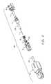
- FIG. 2is an exploded view of the optical attenuator of FIG. 1 ;
- FIG. 3is a perspective view of an interconnection housing of the optical attenuator of FIG. 1 ;
- FIG. 4is a cross-sectional view of the interconnection housing of FIG. 3 ;
- FIG. 5is a perspective view of a latch of the optical attenuator of FIG. 1 ;
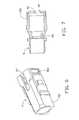
- FIG. 6is a perspective view of a plug housing of the optical attenuator of FIG. 1 ;
- FIG. 7is a cross-sectional view of the plug housing of FIG. 6 ;
- FIG. 8is a cross-sectional view of the optical attenuator of FIG. 1 ;
- FIG. 9is a cross-sectional view of a conventional optical attenuator.
- an optical attenuator 100comprises an optical attenuation fiber 1 , two ferrules 2 A, 2 B, an alignment sleeve 4 , a spring 5 , a flange 6 , an interconnection housing 7 , a latch 8 , a plug housing 9 and a cover 10 .
- the optical fiber 1is doped with cobalt, or similar elements, and can attenuate by a predetermined amount a light beam propagating therethrough.
- the ferrules 2 A and 28are round rods, and each of them defines a through hole (not labeled) longitudinally therethrough for retaining the optical fiber 1 .
- the flange 6comprises four projections 62 formed on a front end thereof.
- the interconnection housing 7comprises a tubular section 70 , and a flange section 77 located rearward of the tubular section 70 .
- a circumferential first flange 71 , a circumferential second flange 72 and a circumferential third flange 73are formed parallel to one another on the flange section 77 , the third flange 73 being at a rear of the interconnection housing 2 .
- a circumferential first groove 74is defined between the first and second flanges 71 , 72
- a circumferential second groove 75is defined between the second and third flanges 72 , 73 .
- two cutouts 76are longitudinally defined from the second flange 72 to a rear end of the interconnection housing 7 . The two cutouts 76 are parallel and opposite to each other.
- a first cavity 702is defined in an interior of the tubular section 70
- a second cavity 722 in communication with the first cavity 702is defined in an interior of the flange section 77 .
- Diameters of the first and second cavities 702 , 722are different from each other, and a step 78 is formed between the first and second cavities 702 , 722 .
- the latch 8comprises two semi-circular sections 81 , a plate 821 , two opposite clamps 822 and a rear sleeve 83 .
- the two opposite clamps 822 and the rear sleeve 83protrude rearwardly from the plate 821 , the clamps 822 being spaced to either side of the sleeve 83 .
- a passage(not labeled) is defined in an interior of the rear sleeve 83 , for retaining the alignment sleeve 4 (see FIG. 8 ).
- a locking tab 823is inwardly formed on an inner surface of each clamp 822 , for engaging with a complementary device (not shown).
- the semi-circular sections 81project forwardly from the plate 821 , and define a cylindrically shaped forward cavity 811 therebetween, for retaining a rear end of the interconnection housing 7 see FIG. 8 ).
- a circular through hole(not labeled) is defined through a center of the plate 821 , communicating between the forward cavity 811 and the passage of the rear sleeve 83 .
- a gap 812is defined in each semi-circular section 81 , for engagingly receiving the third flange 73 of the interconnection housing 7 see FIG. 8 ).
- a C-shaped beam 813is formed in front of each gap 812 and on an inner surface of each semi-circular section 81 , for engaging in the second groove 75 .
- the plug housing 9is generally rectangular in shape.
- a rectangular gap 921is defined in a rear end of each sidewall 92 , for engaging with the first flange 71 of the interconnection housing 7 see FIG. 8 ).
- a circumferential protrusion 97is formed on an inner surface of a rear end of the plug housing 9 , for engaging in the first groove 74 of the interconnection housing 7 .
- a first chamber 94is defined in the rear end of the plug housing 9 , and a second chamber 95 in communication with the first chamber 94 is defined in a center of the plug housing 9 .
- the second chamber 95has a smaller diameter than the first chamber 94 .
- the optical fiber 1is inserted into the ferrules 2 A, 2 B.
- the spring 5encloses the flange 6 .
- the ferrules 2 A, 2 B with the optical fiber 1are fastened into the flange 6 , with a rear end face of the ferrule 2 A and a front end face of the ferrule 2 B being abutted against one another.
- the optical fiber 1is then glued in the ferrules 2 A, 2 B.
- the flange 6 with the ferrules 2 A, 2 B and the spring 5is positioned into the first cavity 702 of the interconnection housing 7 , with a rear end of the ferrule 2 B and the optical fiber 1 passing through the interconnection housing 7 .
- the alignment sleeve 4encloses and is attached to a rear end of the ferrule 2 B and is partially retained in the second cavity 722 of the interconnection housing 7 , and the front end of the alignment sleeve 4 abuts the step 78 .
- the latch 8encloses a rear of the alignment sleeve 4 , the rear of the alignment sleeve 4 protruding into the passage of the latch 8 , and the latch 8 engages with the interconnection housing 7 .
- the third flange 73 of the interconnection housing 7is snapped into the gap 812 of the latch 8 , with the C-shaped beams 813 of the latch 8 locked in the second groove 75 , and a forward lip (not labeled) of each semi-circular section 81 of the latch 8 rides on the second flange 72 of the interconnection housing 7 .
- a reliable and firm engagementis provided between the latch 8 and the interconnection housing 7 .
- the plug housing 9encloses the tubular section 70 of the interconnection housing 7 .
- the circumferential protrusion 97 of the plug housing 9is snapped into the first groove 74 of the interconnection housing 7 , with a rear end of the protrusion 97 riding on the second flange 72 , and the gaps 921 lockingly receive the first flange 71 , thereby fastening the interconnection housing 7 and the plug housing 9 together.
- the four projections 62 of the flange 6are retained in the second chamber 95 of the plug housing 9 , which serves to prevent the ferrules 2 A, 2 B from rotating.
- cover 10is retainingly attached over all the aforesaid components.
- a front end of the ferrule 2 Ais exposed outside the cover 10 , for connecting with one complementary optical connector (not shown).
- the optical attenuator 100 of the present inventionusing the interconnection housing 7 to fasten the latch 8 and the plug housing 9 together, is more firm and reliable and can be assembled more easily and efficiently.
Landscapes
- Physics & Mathematics (AREA)
- General Physics & Mathematics (AREA)
- Optics & Photonics (AREA)
- Mechanical Coupling Of Light Guides (AREA)
Abstract
Description
Claims (10)
Applications Claiming Priority (2)
| Application Number | Priority Date | Filing Date | Title |
|---|---|---|---|
| TW090220079UTW509334U (en) | 2001-11-21 | 2001-11-21 | Optical fiber attenuator |
| TW90220079 | 2001-11-21 |
Publications (2)
| Publication Number | Publication Date |
|---|---|
| US20030095780A1 US20030095780A1 (en) | 2003-05-22 |
| US6873784B2true US6873784B2 (en) | 2005-03-29 |
Family
ID=21687401
Family Applications (1)
| Application Number | Title | Priority Date | Filing Date |
|---|---|---|---|
| US10/238,168Expired - Fee RelatedUS6873784B2 (en) | 2001-11-21 | 2002-09-09 | Optical attenuator |
Country Status (2)
| Country | Link |
|---|---|
| US (1) | US6873784B2 (en) |
| TW (1) | TW509334U (en) |
Cited By (2)
| Publication number | Priority date | Publication date | Assignee | Title |
|---|---|---|---|---|
| CN103336335A (en)* | 2013-06-26 | 2013-10-02 | 华为技术有限公司 | Optical device |
| US9933582B1 (en)* | 2016-11-30 | 2018-04-03 | Yu-Ching Lin | Optical fiber connector |
Families Citing this family (17)
| Publication number | Priority date | Publication date | Assignee | Title |
|---|---|---|---|---|
| JP4056941B2 (en)* | 2003-06-17 | 2008-03-05 | Smk株式会社 | Optical fixed attenuator and manufacturing method thereof |
| US6962445B2 (en) | 2003-09-08 | 2005-11-08 | Adc Telecommunications, Inc. | Ruggedized fiber optic connection |
| US7264404B2 (en)* | 2004-10-29 | 2007-09-04 | Weatherford/Lamb, Inc. | Optical connector assembly |
| US7572065B2 (en) | 2007-01-24 | 2009-08-11 | Adc Telecommunications, Inc. | Hardened fiber optic connector |
| US7591595B2 (en)* | 2007-01-24 | 2009-09-22 | Adc Telelcommunications, Inc. | Hardened fiber optic adapter |
| US7614797B2 (en)* | 2007-01-24 | 2009-11-10 | Adc Telecommunications, Inc. | Fiber optic connector mechanical interface converter |
| US7677814B2 (en)* | 2007-05-06 | 2010-03-16 | Adc Telecommunications, Inc. | Mechanical interface converter for making non-ruggedized fiber optic connectors compatible with a ruggedized fiber optic adapter |
| US7722258B2 (en)* | 2007-05-06 | 2010-05-25 | Adc Telecommunications, Inc. | Interface converter for SC fiber optic connectors |
| US7762726B2 (en) | 2007-12-11 | 2010-07-27 | Adc Telecommunications, Inc. | Hardened fiber optic connection system |
| US9052477B2 (en) | 2009-10-29 | 2015-06-09 | Sumitomo Electric Industries, Ltd. | Optical transceiver with inner fiber set within tray securing thermal path from electronic device to housing |
| US8821039B2 (en) | 2009-10-29 | 2014-09-02 | Sumitomo Electric Industries, Ltd. | Optical transceiver having optical receptacle arranged diagonally to longitudinal axis |
| WO2011052802A2 (en)* | 2009-10-29 | 2011-05-05 | Sumitomo Electric Industries, Ltd. | Pluggable optical transceiver and method for manufacturing the same |
| WO2014206976A1 (en) | 2013-06-27 | 2014-12-31 | Tyco Electronics Raychem Bvba | Fiber optic cable anchoring device for use with fiber optic connectors and methods of using the same |
| CN105445858B (en)* | 2014-07-25 | 2018-04-06 | 鸿富锦精密工业(深圳)有限公司 | Optic fibre fixing device |
| CN105158856B (en)* | 2015-06-19 | 2017-05-24 | 武汉光迅科技股份有限公司 | Pluggable optical passive device |
| FR3050286A1 (en) | 2016-04-14 | 2017-10-20 | Interlemo Holding Sa | CONTACTOR ELEMENT FOR OPTICAL CONNECTOR |
| CN109425940A (en)* | 2017-09-01 | 2019-03-05 | 中航光电科技股份有限公司 | A kind of fiber optic connector assembly and its optical fiber connector, contact |
Citations (7)
| Publication number | Priority date | Publication date | Assignee | Title |
|---|---|---|---|---|
| JPH0325403A (en)* | 1989-06-23 | 1991-02-04 | Nec Corp | Optical attenuator |
| JPH06294911A (en)* | 1993-04-08 | 1994-10-21 | Toray Ind Inc | Optical fixed attenuator and its manufacture |
| US6341191B1 (en)* | 1998-07-07 | 2002-01-22 | Seikoh Giken Co., Ltd. | Variable attenuation type optical power attenuator with latching ratchet |
| US6450695B1 (en)* | 1999-01-28 | 2002-09-17 | Hirose Electric Co., Ltd. | Optical connector |
| US6522485B2 (en)* | 2001-01-19 | 2003-02-18 | Hirose Electric Co., Ltd. | Optical connector |
| US20040033028A1 (en)* | 2002-08-13 | 2004-02-19 | Cheng Yung Chang | Optical fiber converter |
| US6738557B2 (en)* | 2001-11-21 | 2004-05-18 | Hon Hai Precision Ind. Co., Ltd. | Optical attenuator having high return loss |
- 2001
- 2001-11-21TWTW090220079Upatent/TW509334U/ennot_activeIP Right Cessation
- 2002
- 2002-09-09USUS10/238,168patent/US6873784B2/ennot_activeExpired - Fee Related
Patent Citations (7)
| Publication number | Priority date | Publication date | Assignee | Title |
|---|---|---|---|---|
| JPH0325403A (en)* | 1989-06-23 | 1991-02-04 | Nec Corp | Optical attenuator |
| JPH06294911A (en)* | 1993-04-08 | 1994-10-21 | Toray Ind Inc | Optical fixed attenuator and its manufacture |
| US6341191B1 (en)* | 1998-07-07 | 2002-01-22 | Seikoh Giken Co., Ltd. | Variable attenuation type optical power attenuator with latching ratchet |
| US6450695B1 (en)* | 1999-01-28 | 2002-09-17 | Hirose Electric Co., Ltd. | Optical connector |
| US6522485B2 (en)* | 2001-01-19 | 2003-02-18 | Hirose Electric Co., Ltd. | Optical connector |
| US6738557B2 (en)* | 2001-11-21 | 2004-05-18 | Hon Hai Precision Ind. Co., Ltd. | Optical attenuator having high return loss |
| US20040033028A1 (en)* | 2002-08-13 | 2004-02-19 | Cheng Yung Chang | Optical fiber converter |
Cited By (3)
| Publication number | Priority date | Publication date | Assignee | Title |
|---|---|---|---|---|
| CN103336335A (en)* | 2013-06-26 | 2013-10-02 | 华为技术有限公司 | Optical device |
| CN103336335B (en)* | 2013-06-26 | 2015-05-27 | 华为技术有限公司 | Optical device |
| US9933582B1 (en)* | 2016-11-30 | 2018-04-03 | Yu-Ching Lin | Optical fiber connector |
Also Published As
| Publication number | Publication date |
|---|---|
| TW509334U (en) | 2002-11-01 |
| US20030095780A1 (en) | 2003-05-22 |
Similar Documents
| Publication | Publication Date | Title |
|---|---|---|
| US6873784B2 (en) | Optical attenuator | |
| US6629782B2 (en) | Tuned fiber optic connector and method | |
| US6347888B1 (en) | Fiber optic adapter, including hybrid connector system | |
| JP2928101B2 (en) | Fiber optic connectors | |
| US5862282A (en) | Optical connector plug and optical connector | |
| US6916120B2 (en) | Fiber optic connector and method | |
| JP4722943B2 (en) | Optical fiber connector assembly | |
| US4838641A (en) | Optical fiber connector | |
| EP0088410B1 (en) | Optical fiber connectors | |
| EP1237023B1 (en) | Ferrule holding structure for optical connector component | |
| US9395500B2 (en) | Optical fiber connector and cable assembly with dual diameter crimp sleeve | |
| EP0971249B1 (en) | Variable optical attenuator with latching ratchet | |
| US4296999A (en) | Optical fibre connectors | |
| US20250130378A1 (en) | Fiber optic connector with epoxy tube with axial float | |
| US5450514A (en) | Optical waveguide terminating sleeve usable with optical waveguide connectors | |
| US12422625B2 (en) | Optical fiber connector for minimizing signal transmission losses | |
| US11846811B2 (en) | Tuned fiber optic connector | |
| EP0598900A1 (en) | Optical waveguide terminating sleeve | |
| EP1193516A2 (en) | Adapter for coupling used with fiber optic connectors | |
| JP3685231B2 (en) | Optical receptacle for optical measurement | |
| CA1133296A (en) | Retainer for terminal in a fiber optic connector | |
| JP2002174752A (en) | Optical connector |
Legal Events
| Date | Code | Title | Description |
|---|---|---|---|
| AS | Assignment | Owner name:HON HAI PRECISION IND. CO., LTD., TAIWAN Free format text:ASSIGNMENT OF ASSIGNORS INTEREST;ASSIGNOR:CHANG, YAO-HAO;REEL/FRAME:013276/0595 Effective date:20020905 | |
| FPAY | Fee payment | Year of fee payment:4 | |
| FPAY | Fee payment | Year of fee payment:8 | |
| AS | Assignment | Owner name:GOLD CHARM LIMITED, SAMOA Free format text:ASSIGNMENT OF ASSIGNORS INTEREST;ASSIGNOR:HON HAI PRECISION INDUSTRY CO., LTD.;REEL/FRAME:029580/0753 Effective date:20121227 | |
| AS | Assignment | Owner name:GOOGLE INC., CALIFORNIA Free format text:ASSIGNMENT OF ASSIGNORS INTEREST;ASSIGNORS:HON HAI PRECISION INDUSTRY CO., LTD;GOLD CHARM LIMITED;HONG FUJIN PRECISION INDUSTRIAL (SHENZHEN) CO.;REEL/FRAME:032743/0832 Effective date:20140228 | |
| REMI | Maintenance fee reminder mailed | ||
| LAPS | Lapse for failure to pay maintenance fees | ||
| STCH | Information on status: patent discontinuation | Free format text:PATENT EXPIRED DUE TO NONPAYMENT OF MAINTENANCE FEES UNDER 37 CFR 1.362 | |
| FP | Lapsed due to failure to pay maintenance fee | Effective date:20170329 | |
| AS | Assignment | Owner name:GOOGLE LLC, CALIFORNIA Free format text:CHANGE OF NAME;ASSIGNOR:GOOGLE INC.;REEL/FRAME:044142/0357 Effective date:20170929 |