US6873575B2 - Wrist-carried camera and watch-type information equipment - Google Patents
Wrist-carried camera and watch-type information equipmentDownload PDFInfo
- Publication number
- US6873575B2 US6873575B2US10/860,026US86002604AUS6873575B2US 6873575 B2US6873575 B2US 6873575B2US 86002604 AUS86002604 AUS 86002604AUS 6873575 B2US6873575 B2US 6873575B2
- Authority
- US
- United States
- Prior art keywords
- mode
- camera
- watch
- display
- hand
- Prior art date
- Legal status (The legal status is an assumption and is not a legal conclusion. Google has not performed a legal analysis and makes no representation as to the accuracy of the status listed.)
- Expired - Lifetime
Links
- 230000007246mechanismEffects0.000abstractdescription11
- 210000004247handAnatomy0.000description37
- 238000003384imaging methodMethods0.000description18
- 230000003287optical effectEffects0.000description16
- 230000006870functionEffects0.000description14
- 210000000707wristAnatomy0.000description10
- 238000000034methodMethods0.000description6
- 239000007787solidSubstances0.000description5
- 238000010586diagramMethods0.000description4
- 238000001514detection methodMethods0.000description3
- 230000004048modificationEffects0.000description3
- 238000012986modificationMethods0.000description3
- 230000004044responseEffects0.000description3
- 230000008569processEffects0.000description2
- 230000008859changeEffects0.000description1
- 238000004891communicationMethods0.000description1
- 230000006835compressionEffects0.000description1
- 238000007906compressionMethods0.000description1
- 238000010276constructionMethods0.000description1
- 230000008602contractionEffects0.000description1
- 230000000694effectsEffects0.000description1
- 239000004973liquid crystal related substanceSubstances0.000description1
- 238000003825pressingMethods0.000description1
Images


Classifications
- G—PHYSICS
- G04—HOROLOGY
- G04B—MECHANICALLY-DRIVEN CLOCKS OR WATCHES; MECHANICAL PARTS OF CLOCKS OR WATCHES IN GENERAL; TIME PIECES USING THE POSITION OF THE SUN, MOON OR STARS
- G04B47/00—Time-pieces combined with other articles which do not interfere with the running or the time-keeping of the time-piece
- G—PHYSICS
- G04—HOROLOGY
- G04G—ELECTRONIC TIME-PIECES
- G04G21/00—Input or output devices integrated in time-pieces
- H—ELECTRICITY
- H04—ELECTRIC COMMUNICATION TECHNIQUE
- H04N—PICTORIAL COMMUNICATION, e.g. TELEVISION
- H04N23/00—Cameras or camera modules comprising electronic image sensors; Control thereof
- H04N23/50—Constructional details
- H—ELECTRICITY
- H04—ELECTRIC COMMUNICATION TECHNIQUE
- H04N—PICTORIAL COMMUNICATION, e.g. TELEVISION
- H04N23/00—Cameras or camera modules comprising electronic image sensors; Control thereof
- H04N23/50—Constructional details
- H04N23/51—Housings
- H—ELECTRICITY
- H04—ELECTRIC COMMUNICATION TECHNIQUE
- H04N—PICTORIAL COMMUNICATION, e.g. TELEVISION
- H04N23/00—Cameras or camera modules comprising electronic image sensors; Control thereof
- H04N23/60—Control of cameras or camera modules
- H04N23/63—Control of cameras or camera modules by using electronic viewfinders
- H04N23/633—Control of cameras or camera modules by using electronic viewfinders for displaying additional information relating to control or operation of the camera
Definitions
- the present inventionrelates generally to a wrist-carried camera and watch-type information equipment, and more particularly to a camera shaped to be worn about the wrist of an operator like a wristwatch, a portable information terminal and other portable small information equipment.
- Japanese Patent Provisional Publication Nos. 5-209973, 8-278382, 10-108152, etc.disclose a variety of wrist-carried cameras.
- the position of the taking lens and the direction of an optical axis of the taking lensare fixed. Accordingly, the operator has to put the wrist with the worn wristwatch-type camera in front of the body to use the functions of the camera, and the operator has to move the body or the wrist to turn the taking lens toward the object. In this case, the operator has to move the wrist in an unnatural way sometimes in order to adjust the angle of view desirably.
- Japanese Patent Provisional Publication No. 10-90442discloses the combination of a wristwatch and a radiotelephone. It proposed to use hands of an analog watch as indicators, which do not only represent time but also indicate which button has been pressed among control buttons arranged at the circumference of the watch. It is, however, impossible to determine at first sight whether the hands of the watch represent the time or indicate the control button.
- the first object of the present inventionis to provide a wrist-carried camera that makes it easier to adjust the angle of view and never imposes a burden on an operator.
- the second object of the present inventionis to provide portable watch-type information equipment that makes it possible to identify a subject of display on a display part.
- the present inventionis directed to a wrist-carried camera, comprising: a camera part including a taking lens and an imaging device capable of converting an image of an object formed through the taking lens into an electronic image signal; a band part capable of being worn about a wrist of an operator; and a connection mechanism connecting the camera part and the band part, the connection mechanism being attached on a portion of the band part and rotatably supporting the camera part.
- the operatorcan wear the wrist-carried camera of the present invention around the wrist like a wristwatch.
- the camera partis capable of rotating with respect to the band part due to the rotation mechanism, so that the taking lens can be turned to a desired direction according to the object. Therefore, the angle of view can easily be adjusted at hand, and the operator does not have to take up an unnatural stance in order to take a picture.
- an image-storing start switchis provided at a part that is never rotated by the rotation mechanism, and hence, the image-storing start switch will never be moved by the rotation of the camera part. It is therefore easy to operate the wrist-carried camera.
- the present inventionis also directed to a watch-type camera comprising: a timepiece; a display part capable of, in a first mode, representing time by means of an hour hand, a minute hand and a second hand according to the timepiece; a camera part including a taking lens and an imaging device capable of, in a second mode, converting an image of an object formed through the taking lens into an electronic image signal; a mode switching device capable of switching the first and second modes; and a controller which turns at least one of the hour hand, the minute hand and the second hand to a direction of an optical axis of the taking lens when the second mode is set.
- the hour hand, the minute hand and the second handmay be existing members; and the display part may comprise a mechanism driving the hour hand, the minute hand and the second hand.
- the display partmay comprise an electronic display which displays images of the hour hand, the minute hand and the second hand.
- the present inventionis also directed to watch-type information equipment, comprising: a timepiece; a display part which represents time by means of an hour hand, a minute hand and a second hand according to the timepiece in a first mode, and which represents information other than the time in a second mode; and a controller which changes actions of the second hand in accordance with switching between the first and second modes.
- the second handis stopped or the display of the second hand is erased.
- the actions of the second handare changed in the second mode for displaying information other than the time in the information equipment, which has a watch function for analog-displaying the time, and other functions other than the watch.
- the operatorcan easily identify the present mode of the information equipment.
- the present inventionis also directed to the watch-type information equipment, further comprising: a camera part including a taking lens and an imaging device capable of, in the second mode, converting an image of an object formed through the taking lens into an electronic image signal.
- the present inventionis also directed to watch-type information equipment comprising: a timepiece; a display part which represents time by means of an hour hand, a minute hand and a second hand according to the timepiece in a first mode, and which represents information other than the time in a second mode; a mode display member rotatably surrounding the display part, the mode display member being provided with a plurality of marks representing modes in the second mode; and a controller which stops, in the second mode, at least one of the hour hand, the minute hand and the second hand to utilize the at least one of the hour hand, the minute hand and the second hand as an indicator indicating one of the marks of the mode display member.
- the mode of the equipmentis displayed on the rotatable mode display member, and the hand of the watch is also used as an indicator. This eliminates the necessity for a special indication means and makes it easier to display the mode.
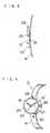
- FIG. 1is an outside drawing showing the front of a wrist-carried electronic camera according to the first embodiment of the present invention
- FIG. 2is an outside drawing showing the backside of an electronic camera in FIG. 1 ;
- FIG. 3is a side view showing an electronic camera in FIG. 1 ;
- FIG. 4is a view showing an example of a time display in a watch mode
- FIG. 5is a view showing an example of the display in a camera mode
- FIG. 6is a block diagram showing an electronic camera according to the first embodiment
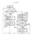
- FIG. 7is a flow chart showing the procedure for controlling an electronic camera according to the first embodiment
- FIG. 8is a block diagram showing an electronic camera according to the second embodiment of the present invention.
- FIG. 9is a flow chart showing the procedure for controlling an electronic camera according to the second embodiment.
- FIG. 10is an outside drawing showing the front side of an electronic camera according to the third embodiment of the present invention.
- FIG. 11is a view showing an example of a display in a camera mode of an electronic camera according to the third embodiment of the present invention.
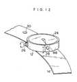
- FIG. 12is a perspective view showing an example of an electronic camera, which has a tilting mechanism arranged at a taking lens.
- FIG. 1is an outside drawing of the front of a wrist-carried electronic camera 10 according to the first embodiment of the present invention.
- FIGS. 2 and 3are a back perspective view and a side view, respectively, of the electronic camera 10 .
- the electronic camera 10comprises a body 12 having watch functions and camera functions and a band 14 capable of being worn about a wrist of an operator.
- the electronic camera 10is shaped like a wristwatch in such a manner as to be worn about the wrist of the operator.
- the body 12connects to a portion of the band 14 through a rotary mechanism 16 , which supports the body 12 rotatably on a normal line of the portion of the band 14 .
- the body 12is capable of turning on an axis perpendicular to a tangent plane of the surface of the connecting portion of the band.
- the body 12has a so-called analog watch type display part 24 provided with an hour hand 18 , a minute hand 20 and a second hand 22 .
- a stem 26is arranged at the right side of the body 12 in FIG. 1 as is the case with an ordinary wristwatch (in the direction of three o'clock on the display of the watch).
- a taking lens 28is arranged at the top side of the body 12 (in the direction of twelve o'clock on the display of the watch). This is the standard arrangement, which aims at directing an optical axis of the taking lens 28 toward an object in front of the operator, who is putting his wrist with the worn camera 10 in front of his body.
- the taking lens 28 and the stem 26are not necessarily provided at the above-mentioned positions.
- the taking lens 28may be buried in the body 12 .
- a solid state imaging device 34such as a CCD is arranged behind the taking lens 28 .
- a processing circuit for processing signals read from the imaging device, a memory, a central processing unit (CPU), and a timepiece or watch operating partare disposed in the body 12 .
- An imaging start instruction switch or a release switch 30is attached to the band 14 . If a release switch were provided at the body 12 , the release switch would shift with the rotation of the body 12 . To address this problem, the release switch 30 is arranged on the band 14 , which is not rotated.
- a mode selectora variety of control buttons, and other control members are arranged at appropriate positions of the band 14 and the body 12 .
- the stem 26is used as the control member such as the mode selector.
- FIG. 4shows an example of the display in a watch mode.
- the hour hand 18 , the minute hand 20 and the second hand 22are driven by the watch operating part according to the rules of the analog time representation system. If the electronic camera 10 is set to the camera mode; the hour hand 18 , the minute hand 20 and the second hand 22 are stopped in the state of pointing to twelve o'clock and along the optical axis of the taking lens 28 (i.e., an image-capturing direction) as shown in FIG. 5 .
- the switching of the display according to the switching of the modeswill be described later in further detail.
- FIG. 6is a block diagram showing the electronic camera 10 .
- the electronic camera 10comprises an optical unit 32 , the solid state imaging device 34 , an imaging circuit 36 , a memory 38 , a storage device 40 , an image processing control CPU 42 , an autofocus (AF) control circuit 44 , a flash control circuit 46 , an electronic flash part 48 , a camera power supply control switch 50 , a CPU with timepiece functions 52 , a display switching circuit 54 , a hand driving unit 56 and a variety of control members 58 .
- AFautofocus
- the optical unit 32includes the taking lens 28 (see FIG. 1 ), and a light from the object enters a light receiving surface of the imaging device 34 through the optical unit 32 .
- the light received by the imaging device 34is photo-electrically converted, and is sequentially read as image signals.
- the imaging circuit 36includes an analog processing part such as a CDS clamp and a gain control amplifier, an A/D converter, and known digital image processing circuits such as a luminance signal generating circuit, a color differential signal generating circuit and a gamma correcting circuit.
- the imaging circuit 36processes the signals read from the imaging device 34 in a predetermined manner under the control of the image processing control CPU 42 , so that the signals can be converted into electronic image data in digital form.
- the electronic camera 10has a known automatic exposure adjustment (AE) function and an AF adjusting device. Only turning the taking lens 28 toward the object adjusts the exposure to the optimum, and the AF control circuit 44 automatically focuses the taking lens 28 . If a flash operation mode is set to an automatic flash mode, the flash control circuit 46 automatically drives the electronic flash part 48 in order to capture an image of the object at a low luminance with the proper exposure.
- AEautomatic exposure adjustment
- the camera power supply control switch 50is turned on and off according to control signals outputted from the CPU 52 .
- the switch 50is off. Setting the camera mode turns on the switch 50 so as to supply the power to the camera block.
- the dotted lines in FIG. 6conceptually represent the supply of the power to each circuit in the camera block.
- the hand driving unit 56includes a drive mechanism for operating the hour hand 18 , the minute hand 20 and the second hand 22 .
- the CPU 52controls the hand driving unit 56 through the display switching circuit 54 .
- the CPU 52has built-in timepiece functions to serve as the watch operating part.
- the CPU 52switches the mode between the watch mode and the camera mode in accordance with the signals outputted from the mode selector included in the control members 58 . More specifically, if the watch mode is selected, the CPU 52 turns off the camera power supply control switch 50 , and sets the display switching circuit 54 to a first display mode or a time display mode. Then, the CPU 52 controls the hand driving unit 56 as is the case with the ordinary analog watch to drive the hands 18 , 20 and 22 , thereby operating the hands 18 , 20 and 22 so that the current time can be shown on the display part 24 .
- the CPU 52turns on the camera power supply control switch 50 to supply the power to the camera block, and sets the display switching circuit 54 to a second display mode or a camera display mode. Then, the CPU 52 controls the hand driving unit 56 to turn the hour hand 18 , the minute hand 20 and the second hand 22 (or at least one of them) to the direction of the optical axis of the taking lens 28 . Then, the CPU 52 stops the driving of the hands 18 , 20 and 22 .
- the hands of the watchrepresent the direction of the taking lens 28 , the operator can easily know the image-capturing direction even if the body 12 is rotated. Moreover, it is particularly desirable to utilize the hands of the watch for displaying the direction of the optical axis of the taking lens, since it is not practical to use an optical finder in the wrist-carried camera shaped like a wristwatch.
- the second hand 22functions as a mode display device for letting the operator know whether the electronic camera 10 is in the watch mode or the camera mode.
- Pressing the release switch 30 in the camera modesupplies an image-storing start signal or a release signal to the CPU 52 , and a predetermined image-storing operation starts in response to the release signal.
- the CPU 52drives the electronic flash part 48 , and captures the image signals read from the solid state imaging device 34 in response to the release signal into the memory 38 through the imaging circuit 36 .
- the image signalsare then compressed or the like to be stored through the storage device 40 in the storage medium.
- the storage mediummay be either an extremely small removable memory card or a flash memory built in the electric camera 10 .
- the image data stored in the storage mediumcan be read through the image processing control CPU 42 , and the read image data are expanded in an contraction/expansion circuit. Then, the image data can be outputted to another external equipment through an output part or a communication part (not shown).
- FIG. 7shows a flow chart showing the procedure for controlling the electronic camera 10 , which is constructed in the above-mentioned manner.
- the CPU 52determines whether the watch mode or the camera mode is selected in accordance with the detection results of the signals outputted from the mode selector included in the control members 58 (S 110 ). If the camera mode is selected, the CPU 52 turns the hands 18 , 20 and 22 of the watch in the same direction as the optical axis of the taking lens 28 , in other words, to twelve o'clock on the display (S 112 ), and stops the hands 18 , 20 and 22 there.
- the CPU 52determines whether the release switch 30 has been pressed or not (S 116 ). If the release switch 30 is pressed, the CPU 52 stores the captured image data through the storage device 40 in the storage medium as described with reference to FIG. 6 (S 118 ). If the release switch 30 is not pressed at S 116 , the processing returns to S 110 .
- the CPU 52turns off the power supply of the camera block, which is not in use, and turns the hands 18 , 20 and 22 to represent the current time (S 120 ). Then, the CPU 52 drives the hands 18 , 20 and 22 to represent the time with the timepiece functions of the CPU 52 (S 122 ).
- the watch modeWhen the watch mode is switched to the camera mode by operating the mode selector or the control member such as the stem 26 , the hands 18 , 20 and 22 are turned to the direction of the taking lens 28 . Therefore, the operator can easily know the image-capturing direction and adjust the angle of view according to the direction of the hands. Since the second hand 22 stops in the camera mode, it is possible to know whether the watch mode or the camera mode is set in accordance with the movement of the second hand 22 .
- the operatorcan easily know the image-capturing direction in the wrist-carried camera that is constructed in such a manner that the image-capturing direction is changed by rotating the body 12 .
- the handinesscan be improved by representing the direction of the taking lens by utilizing the hands of the watch as mentioned above.
- the electronic camera 10 of this embodimentis constructed in such a manner that the body 12 with the taking lens 28 is rotatable with respect to the band 14 . Therefore, the taking lens 28 can easily be turned toward a desired object by rotating the body 12 in the camera mode. Thus, the operator does not have to move the body or the wrist in an unnatural way, and the operator is not physically burdened.
- the release switch 30is provided at the unrotating band 14 , and therefore, the release switch 30 is fixed at a predetermined position regardless of the rotation of the body 12 . This facilitates the operation of the release switch 30 . It is also possible to turn the taking lens 28 toward the operator by rotating the body 12 , and thus, the operator can easily capture an image of oneself.
- all of the hour hand 18 , the minute hand 20 and the second hand 22are turned to the twelve o'clock (along the optical axis of the taking lens 28 ) on the display 24 ; however, the present invention should not be restricted to this. All the hands of the watch do not necessarily point to the twelve o'clock, and at least predetermined one of the hands may represent the image-capturing direction.
- the idea that the hand of the watch is used to represent the direction of the taking lens 28 in the camera modemay be applied to a wide variety of watch-type cameras such as a wristwatch-type camera that is not provided with the rotation mechanism 16 , and a watch-type camera that is not provided with the band (e.g., a pocket-watch-type camera).
- the hands of the watchare not restricted to the existing mechanical structures, but they may be embodied by displaying on a display unit such as an onscreen display. According to the second embodiment, the hands of the watch are embodied by the display on the display unit.
- FIG. 8is a block diagram showing the electronic camera according to the second embodiment of the present invention. Parts similar to those described with reference to FIG. 6 are denoted by the same reference numerals, and they will not be described.
- the electronic camera of the second embodimentis provided with a display switching circuit 70 and a display unit 72 instead of the display switching circuit 54 and the hand driving unit 56 in FIG. 6 .
- the display unit 72such as a liquid crystal display is built in the body 12 in FIG. 1 . More specifically, a display screen of the display unit 72 is arranged at a part corresponding to the display part 24 of the body 12 .
- the display unit 72can switch displaying and not displaying images of the hour hand 18 , the minute hand 20 and the second hand 22 according to the display switching circuit 70 .
- the display unit 72is used to represent the time with the images of the hands, and the display unit 72 is also used to display a captured image.
- the hands of the watchare displayed on the screen of the display unit 72 , and the present time is represented according to the rules of the analog time representation system.
- the hands of the watchare not displayed, and the image data captured through the solid state imaging device 34 is supplied to the display unit 72 through the display switching circuit 70 so that the captured image can be displayed on the screen of the display unit 72 .
- a movie imagewhich is captured by the camera before the instruction is given to start the image-storing, is displayed on the display unit 72 , the operator can determine the angle of view while looking at the movie image. In this case, however, the battery is exhausted quickly.
- a switching devicecapable of turning on and off the display of the movie image on the display unit 72 . If the operator selects an power-saving mode or a movie-off mode, the power supply of the camera block is turned off to save the power, and the hand of the watch on the display unit 72 is turned to the direction of the optical axis of the taking lens 28 as shown in FIG. 5 , thus indicating the direction of the optical axis of the taking lens 28 or the image-capturing direction. The operator can adjust the optical axis of the taking lens 28 with reference to the indication of the hand. Then, the depression of the release switch 30 turns on the power supply of the camera block to execute the image capturing and storing.
- the broken lineimaginarily indicates a movie image display area 74 if the display unit 72 is used as the display part 24 .
- FIG. 9is a flow chart showing the procedure for controlling the electronic camera according to the second embodiment, which is constructed in the above-mentioned manner.
- the CPU 52determines whether the watch mode or the camera mode is selected according to the detection results of the signals inputted from the mode selector included in the control members 58 (S 210 ). If the watch mode is selected, the power supply of the camera is turned off so as not to display the movie image (S 212 ). Then, the hands of the watch are displayed on the display part 24 while being turned to the positions for representing the present time (S 214 ).
- the CPU 52determines whether the movie-on mode is set or not (S 216 ). If the movie-on mode is determined as being selected according to the detection of the signals inputted from the mode selector included in the control members 58 , the hands of the watch are not displayed (S 218 ), and the power supply of the camera is turned on to drive the solid state imaging device 34 , the imaging circuit 36 , etc. so as to display the movie image on the display unit 72 (S 220 ).
- the movie-off modeis determined as being selected at S 216 , only the hands of the watch are displayed (S 222 ) and they are turned to the direction of the optical axis of the taking lens 28 (S 224 ). Then, whether the release switch 30 has been pressed or not is determined (S 226 ). If the release switch 30 has not been turned on, the process returns to S 210 to wait for the input of the image-storing start instruction. If the operator presses the release switch 30 , the image-storing is performed, and the captured image data is stored through the storage device 40 in the storage medium (S 228 ).
- FIG. 10shows an embodiment in which the watch-type information equipment according to the present invention is applied to the wrist-carried electronic camera. Parts similar to those described with reference to FIG. 1 are denoted by the same reference numerals, and they will not be described here.
- the hands of the watchmay be mechanical as is the case with the first embodiment, or the display unit may be used to display the images of hands of the watch as is the second embodiment.
- the taking lens (not illustrated in FIG. 10 ) of an electronic camera 80 in FIG. 10is incorporated in the body 12 , and does not project from the body 12 .
- the taking lensis arranged in the direction of the twelve o'clock as is the case with in FIG. 1 .
- a bezel 82is arranged to surround the display part 24 , and is rotatably attached to the top of the body 12 .
- Marks 83 , 84 and 85 indicating the operation modes of the cameraare formed on the bezel 82 , and the bezel 82 functions as a mode selecting member. Examples of the camera operation modes are an image-storing mode for capturing and storing images, a reproduction mode for reproducing stored images, and an erasing mode for erasing unnecessary images among stored images.
- the central mark 83indicates the image-storing mode
- the right mark 84indicates the reproduction mode
- the left mark 85indicates the erasing mode.
- Other marksmay also be formed to indicate other operation modes.
- the hour hand 18 , the minute hand 20 and the second hand 22are driven to represent the time according to the rules of the analog watch display.
- all the hour hands 18 , the minute hand 20 and the second hand 22 (or at least one of them)are fixed in the direction of the twelve o'clock on the display of the watch to indicate the image-capturing direction.
- These handsare also used as an indicator for pointing to one of the mode display marks ( 83 , 84 , 85 ) on the bezel.
- the camera operation modeis set by rotating the bezel 82 to set the desired mark to the hands ( 18 , 20 , 22 ) of the watch as the indicator.
- the operation modesare switched and displayed by the combination of the mode display marks on the rotary bezel 82 and the hands of the watch.
- the wristwatch-type camerahas been explained with reference to FIGS. 10 and 11 ; however, the idea that the combination of the rotary control member with the mode display marks and the hands of the watch is used to switch the modes and display the present mode may also be applied to a wide variety of other information equipment.
- a tilt mechanism 88is provided at the supporting part of the taking lens 28 in order to vertically tilt the taking lens 28 in connection with the operation of the stem 26 .
- the electronic cameras according to the above-described embodimentsrecord the still images; however, the present invention may also be applied to an electronic camera for recording movie images.
- the electronic camera for recording movie imagesalthough a recording start/stop button such as a VTR switch should be provided instead of the release switch and other modifications should be made, the electronic camera for recording the movie images according to the present invention can achieve the same effects as the above-described embodiments.
- the wristwatch type camera according to the present inventionhas the camera part that is rotatably attached to the band part. This makes it possible to turn the taking lens to a desired direction according to the object. Therefore, the angle of view can easily be adjusted at hand, and the operator does not have to take up an unnatural posture.
- the image-storing start switchis not arranged at the rotary part, and thus, the image-storing can be started by operating the image-storing start switch at the same part even if the camera part is rotated.
- the hands of the watchrepresent the direction of the taking lens in the camera mode so that the operator can easily know the image-capturing direction.
- the state of the second handis changed in the mode for displaying the information except for the time.
- the operatorcan easily identify the present mode of the information equipment by paying attention to the state of the second hand.
- the mode of the equipmentis displayed on the rotary mode display member, and the hands of the watch also function as the indicator. This makes it possible to easily display the mode without providing any special indicator.
Landscapes
- Engineering & Computer Science (AREA)
- Multimedia (AREA)
- Signal Processing (AREA)
- Physics & Mathematics (AREA)
- General Physics & Mathematics (AREA)
- Electric Clocks (AREA)
- Electromechanical Clocks (AREA)
- Camera Bodies And Camera Details Or Accessories (AREA)
- Accessories Of Cameras (AREA)
- Studio Devices (AREA)
Abstract
Description
Claims (1)
Priority Applications (1)
| Application Number | Priority Date | Filing Date | Title |
|---|---|---|---|
| US10/860,026US6873575B2 (en) | 1998-11-06 | 2004-06-04 | Wrist-carried camera and watch-type information equipment |
Applications Claiming Priority (4)
| Application Number | Priority Date | Filing Date | Title |
|---|---|---|---|
| JP31605498AJP3988102B2 (en) | 1998-11-06 | 1998-11-06 | Arm-mounted camera |
| JP10-316054 | 1998-11-06 | ||
| US09/432,090US6809774B1 (en) | 1998-11-06 | 1999-11-02 | Wrist-carried camera and watch-type information equipment |
| US10/860,026US6873575B2 (en) | 1998-11-06 | 2004-06-04 | Wrist-carried camera and watch-type information equipment |
Related Parent Applications (1)
| Application Number | Title | Priority Date | Filing Date |
|---|---|---|---|
| US09/432,090ContinuationUS6809774B1 (en) | 1998-11-06 | 1999-11-02 | Wrist-carried camera and watch-type information equipment |
Publications (2)
| Publication Number | Publication Date |
|---|---|
| US20040218474A1 US20040218474A1 (en) | 2004-11-04 |
| US6873575B2true US6873575B2 (en) | 2005-03-29 |
Family
ID=18072758
Family Applications (2)
| Application Number | Title | Priority Date | Filing Date |
|---|---|---|---|
| US09/432,090Expired - Fee RelatedUS6809774B1 (en) | 1998-11-06 | 1999-11-02 | Wrist-carried camera and watch-type information equipment |
| US10/860,026Expired - LifetimeUS6873575B2 (en) | 1998-11-06 | 2004-06-04 | Wrist-carried camera and watch-type information equipment |
Family Applications Before (1)
| Application Number | Title | Priority Date | Filing Date |
|---|---|---|---|
| US09/432,090Expired - Fee RelatedUS6809774B1 (en) | 1998-11-06 | 1999-11-02 | Wrist-carried camera and watch-type information equipment |
Country Status (2)
| Country | Link |
|---|---|
| US (2) | US6809774B1 (en) |
| JP (1) | JP3988102B2 (en) |
Cited By (14)
| Publication number | Priority date | Publication date | Assignee | Title |
|---|---|---|---|---|
| US8279716B1 (en)* | 2011-10-26 | 2012-10-02 | Google Inc. | Smart-watch including flip up display |
| US8467270B2 (en) | 2011-10-26 | 2013-06-18 | Google Inc. | Smart-watch with user interface features |
| US20140143737A1 (en)* | 2012-11-20 | 2014-05-22 | Samsung Electronics Company, Ltd. | Transition and Interaction Model for Wearable Electronic Device |
| US20150205361A1 (en)* | 2014-01-22 | 2015-07-23 | Princo Middle East Fze | Time adjusting method and system for wristwatch |
| US9477313B2 (en) | 2012-11-20 | 2016-10-25 | Samsung Electronics Co., Ltd. | User gesture input to wearable electronic device involving outward-facing sensor of device |
| WO2017201659A1 (en)* | 2016-05-23 | 2017-11-30 | 深圳市蔚蓝滨海产业投资有限公司 | Smart watch |
| US10185416B2 (en) | 2012-11-20 | 2019-01-22 | Samsung Electronics Co., Ltd. | User gesture input to wearable electronic device involving movement of device |
| US10194060B2 (en) | 2012-11-20 | 2019-01-29 | Samsung Electronics Company, Ltd. | Wearable electronic device |
| US10423214B2 (en) | 2012-11-20 | 2019-09-24 | Samsung Electronics Company, Ltd | Delegating processing from wearable electronic device |
| US10551928B2 (en) | 2012-11-20 | 2020-02-04 | Samsung Electronics Company, Ltd. | GUI transitions on wearable electronic device |
| US10579202B2 (en) | 2012-12-28 | 2020-03-03 | Glide Talk Ltd. | Proactively preparing to display multimedia data |
| US10691332B2 (en) | 2014-02-28 | 2020-06-23 | Samsung Electronics Company, Ltd. | Text input on an interactive display |
| US11157436B2 (en) | 2012-11-20 | 2021-10-26 | Samsung Electronics Company, Ltd. | Services associated with wearable electronic device |
| US11237719B2 (en) | 2012-11-20 | 2022-02-01 | Samsung Electronics Company, Ltd. | Controlling remote electronic device with wearable electronic device |
Families Citing this family (40)
| Publication number | Priority date | Publication date | Assignee | Title |
|---|---|---|---|---|
| JP2005012428A (en) | 2003-06-18 | 2005-01-13 | Seiko Epson Corp | Digital camera |
| US20050111308A1 (en)* | 2003-11-20 | 2005-05-26 | Hosey Michael J. | Display device with hinged stand |
| KR100608732B1 (en) | 2003-12-26 | 2006-08-04 | 엘지전자 주식회사 | Portable terminal with digital camera function |
| US20060055691A1 (en)* | 2004-09-11 | 2006-03-16 | Bursett Jeffrey M | Attachable informational appliance |
| US20070075956A1 (en)* | 2004-11-04 | 2007-04-05 | Matsushita Electric Industrial Co., Ltd. | Mobile terminal apparatus |
| JP4931693B2 (en)* | 2007-05-21 | 2012-05-16 | オリンパスイメージング株式会社 | Information equipment |
| WO2009131573A1 (en)* | 2008-04-22 | 2009-10-29 | Relyea Gregg F | Graphic display programmable wristwatch |
| US8627220B2 (en)* | 2009-10-01 | 2014-01-07 | Blackberry Limited | Apparatus and method for invoking a function based on a gesture input |
| KR20140048319A (en) | 2011-08-05 | 2014-04-23 | 지유아이 글로벌 프로덕츠 엘티디. | Apparatus for cleaning view screens and lenses and method for the use thereof |
| EP2579107B1 (en)* | 2011-10-05 | 2020-09-02 | Suunto Oy | Watchcase and wrist watch device |
| EP2915416A4 (en) | 2012-11-05 | 2016-11-02 | Gui Global Products Ltd | DEVICES AND ACCESSORIES USING AN ACTIVE HINGE |
| US20200137906A9 (en) | 2012-11-05 | 2020-04-30 | Gui Global Products, Ltd. | Devices and accessories employing a living hinge |
| US9030446B2 (en)* | 2012-11-20 | 2015-05-12 | Samsung Electronics Co., Ltd. | Placement of optical sensor on wearable electronic device |
| KR102138503B1 (en)* | 2013-04-09 | 2020-07-28 | 엘지전자 주식회사 | Smart watch |
| KR102112305B1 (en)* | 2013-09-02 | 2020-05-18 | 삼성전자주식회사 | Wearable electronic device |
| KR102157313B1 (en)* | 2013-09-03 | 2020-10-23 | 삼성전자주식회사 | Method and computer readable recording medium for recognizing an object using a captured image |
| JPWO2015076206A1 (en)* | 2013-11-22 | 2017-03-16 | シャープ株式会社 | Communication terminal, communication terminal control method, and control program |
| JP6241230B2 (en)* | 2013-11-28 | 2017-12-06 | 富士通株式会社 | Biological information determination apparatus and program |
| JP5872529B2 (en)* | 2013-12-24 | 2016-03-01 | 梅州市▲ショウ▼瑩實業有限公司 | Wristwatch structure with interchangeable built-in lens |
| US20150185704A1 (en)* | 2013-12-30 | 2015-07-02 | Tau-Jeng Hsu | Electronic watch structure capable of selectively mounting a camera lens |
| EP2891942B1 (en)* | 2014-01-02 | 2018-08-22 | LG Electronics Inc. | Wearable terminal |
| JP6434724B2 (en)* | 2014-07-01 | 2018-12-05 | パナソニック インテレクチュアル プロパティ コーポレーション オブ アメリカPanasonic Intellectual Property Corporation of America | Information communication method |
| USD795709S1 (en)* | 2014-09-10 | 2017-08-29 | Google Inc. | Camera watch |
| JP5971309B2 (en)* | 2014-11-13 | 2016-08-17 | カシオ計算機株式会社 | Portable terminal device and process execution method |
| KR20160083690A (en)* | 2015-01-02 | 2016-07-12 | 삼성전자주식회사 | Electronic device having rotation member and method thereof |
| US10386941B2 (en) | 2015-06-16 | 2019-08-20 | Intel Corporation | Gyratory sensing system to enhance wearable device user experience via HMI extension |
| KR102459243B1 (en)* | 2015-10-08 | 2022-10-26 | 삼성전자 주식회사 | Electronic device and method for photographing thereof |
| JP6341192B2 (en)* | 2015-12-22 | 2018-06-13 | カシオ計算機株式会社 | Information processing apparatus, control method, and program |
| WO2017141220A1 (en)* | 2016-02-19 | 2017-08-24 | Amardeep Singh | A wrist and head mounted camera |
| US10129503B1 (en) | 2016-09-20 | 2018-11-13 | Apple Inc. | Image-capturing watch |
| CN207115040U (en)* | 2017-05-08 | 2018-03-16 | 北京搜狗科技发展有限公司 | A kind of table body and a kind of wearable device |
| CN109143830A (en)* | 2018-09-03 | 2019-01-04 | 出门问问信息科技有限公司 | watch device |
| USD924078S1 (en)* | 2019-10-25 | 2021-07-06 | Robert Charles DeMaio | Watch with bezel |
| CN110995991B (en)* | 2019-11-28 | 2021-11-16 | 维沃移动通信有限公司 | Camera control method and wearable device |
| JP2021105690A (en)* | 2019-12-27 | 2021-07-26 | キヤノン株式会社 | Imaging apparatus |
| WO2021151090A1 (en)* | 2020-01-24 | 2021-07-29 | Arizona Board Of Regents On Behalf Of Arizona State University | Systems and methods including a device for personalized activity monitoring involving the hands |
| CN111638638A (en)* | 2020-05-06 | 2020-09-08 | 瑞声通讯科技(常州)有限公司 | Wrist-wearing device |
| USD957498S1 (en)* | 2020-06-25 | 2022-07-12 | Canon Kabushiki Kaisha | Digital camera |
| CN112433464B (en)* | 2020-11-19 | 2022-03-15 | 桃源县职业中等专业学校 | Children fix a position camera rotary device for wrist-watch and anti-disengaging mechanism thereof |
| CN112506025B (en)* | 2020-11-24 | 2022-03-22 | 维沃移动通信有限公司 | Wearable device and shooting method thereof |
Citations (14)
| Publication number | Priority date | Publication date | Assignee | Title |
|---|---|---|---|---|
| US4362398A (en) | 1980-10-14 | 1982-12-07 | Timex Corporation | Multiplexed LCD analog timepiece |
| JPH05209973A (en) | 1992-05-13 | 1993-08-20 | Casio Comput Co Ltd | Electronic information equipment |
| US5329501A (en) | 1992-10-08 | 1994-07-12 | Eta Sa Fabriques D'ebauches | Timepiece adapted to receive radio broadcast messages to be displayed by its hands |
| US5475653A (en) | 1993-12-17 | 1995-12-12 | Seiko Communications Holding N.V. | Analog wristwatch paging receiver |
| JPH08278382A (en) | 1995-12-13 | 1996-10-22 | Casio Comput Co Ltd | Electronic watch |
| US5572196A (en) | 1993-05-10 | 1996-11-05 | Sakumoto; Kazumi | Electronic analog watch with pager |
| US5572488A (en) | 1993-12-17 | 1996-11-05 | Seiko Communications Holding N.V. | Wristwatch paging receiver having analog message display |
| JPH1090442A (en) | 1996-07-31 | 1998-04-10 | Motorola Inc | Key pad array of wrist watch type radiotelephon equipment |
| JPH10108152A (en) | 1996-09-27 | 1998-04-24 | Sanyo Electric Co Ltd | Portable information terminal |
| US5977535A (en) | 1992-09-30 | 1999-11-02 | Lsi Logic Corporation | Light sensing device having an array of photosensitive elements coincident with an array of lens formed on an optically transmissive material |
| US20010011025A1 (en) | 2000-01-31 | 2001-08-02 | Yuji Ohki | Receiver wearable on user's wrist |
| US20010017663A1 (en) | 1999-12-28 | 2001-08-30 | Ryusuke Yamaguchi | Portable image capturing device |
| US6359837B1 (en) | 1999-06-30 | 2002-03-19 | Casio Computer Co., Ltd. | Camera, camera system, information recording system, timepiece, and link system for camera and timepiece |
| US20020180586A1 (en) | 2001-05-30 | 2002-12-05 | Kitson Frederick Lee | Face and environment sensing watch |
Family Cites Families (1)
| Publication number | Priority date | Publication date | Assignee | Title |
|---|---|---|---|---|
| JPH0664164B2 (en)* | 1985-07-08 | 1994-08-22 | カシオ計算機株式会社 | Electronic wrist watch with camera |
- 1998
- 1998-11-06JPJP31605498Apatent/JP3988102B2/ennot_activeExpired - Fee Related
- 1999
- 1999-11-02USUS09/432,090patent/US6809774B1/ennot_activeExpired - Fee Related
- 2004
- 2004-06-04USUS10/860,026patent/US6873575B2/ennot_activeExpired - Lifetime
Patent Citations (14)
| Publication number | Priority date | Publication date | Assignee | Title |
|---|---|---|---|---|
| US4362398A (en) | 1980-10-14 | 1982-12-07 | Timex Corporation | Multiplexed LCD analog timepiece |
| JPH05209973A (en) | 1992-05-13 | 1993-08-20 | Casio Comput Co Ltd | Electronic information equipment |
| US5977535A (en) | 1992-09-30 | 1999-11-02 | Lsi Logic Corporation | Light sensing device having an array of photosensitive elements coincident with an array of lens formed on an optically transmissive material |
| US5329501A (en) | 1992-10-08 | 1994-07-12 | Eta Sa Fabriques D'ebauches | Timepiece adapted to receive radio broadcast messages to be displayed by its hands |
| US5572196A (en) | 1993-05-10 | 1996-11-05 | Sakumoto; Kazumi | Electronic analog watch with pager |
| US5475653A (en) | 1993-12-17 | 1995-12-12 | Seiko Communications Holding N.V. | Analog wristwatch paging receiver |
| US5572488A (en) | 1993-12-17 | 1996-11-05 | Seiko Communications Holding N.V. | Wristwatch paging receiver having analog message display |
| JPH08278382A (en) | 1995-12-13 | 1996-10-22 | Casio Comput Co Ltd | Electronic watch |
| JPH1090442A (en) | 1996-07-31 | 1998-04-10 | Motorola Inc | Key pad array of wrist watch type radiotelephon equipment |
| JPH10108152A (en) | 1996-09-27 | 1998-04-24 | Sanyo Electric Co Ltd | Portable information terminal |
| US6359837B1 (en) | 1999-06-30 | 2002-03-19 | Casio Computer Co., Ltd. | Camera, camera system, information recording system, timepiece, and link system for camera and timepiece |
| US20010017663A1 (en) | 1999-12-28 | 2001-08-30 | Ryusuke Yamaguchi | Portable image capturing device |
| US20010011025A1 (en) | 2000-01-31 | 2001-08-02 | Yuji Ohki | Receiver wearable on user's wrist |
| US20020180586A1 (en) | 2001-05-30 | 2002-12-05 | Kitson Frederick Lee | Face and environment sensing watch |
Cited By (22)
| Publication number | Priority date | Publication date | Assignee | Title |
|---|---|---|---|---|
| US8902714B2 (en) | 2011-10-26 | 2014-12-02 | Google Inc. | Smart-watch including flip up display |
| US8379488B1 (en) | 2011-10-26 | 2013-02-19 | Google Inc. | Smart-watch including flip up display |
| US8467270B2 (en) | 2011-10-26 | 2013-06-18 | Google Inc. | Smart-watch with user interface features |
| US8279716B1 (en)* | 2011-10-26 | 2012-10-02 | Google Inc. | Smart-watch including flip up display |
| US9477313B2 (en) | 2012-11-20 | 2016-10-25 | Samsung Electronics Co., Ltd. | User gesture input to wearable electronic device involving outward-facing sensor of device |
| US11372536B2 (en)* | 2012-11-20 | 2022-06-28 | Samsung Electronics Company, Ltd. | Transition and interaction model for wearable electronic device |
| US20140143737A1 (en)* | 2012-11-20 | 2014-05-22 | Samsung Electronics Company, Ltd. | Transition and Interaction Model for Wearable Electronic Device |
| US11237719B2 (en) | 2012-11-20 | 2022-02-01 | Samsung Electronics Company, Ltd. | Controlling remote electronic device with wearable electronic device |
| US11157436B2 (en) | 2012-11-20 | 2021-10-26 | Samsung Electronics Company, Ltd. | Services associated with wearable electronic device |
| US10185416B2 (en) | 2012-11-20 | 2019-01-22 | Samsung Electronics Co., Ltd. | User gesture input to wearable electronic device involving movement of device |
| US10194060B2 (en) | 2012-11-20 | 2019-01-29 | Samsung Electronics Company, Ltd. | Wearable electronic device |
| US10423214B2 (en) | 2012-11-20 | 2019-09-24 | Samsung Electronics Company, Ltd | Delegating processing from wearable electronic device |
| US10551928B2 (en) | 2012-11-20 | 2020-02-04 | Samsung Electronics Company, Ltd. | GUI transitions on wearable electronic device |
| US10678393B2 (en) | 2012-12-28 | 2020-06-09 | Glide Talk Ltd. | Capturing multimedia data based on user action |
| US10599280B2 (en) | 2012-12-28 | 2020-03-24 | Glide Talk Ltd. | Dual mode multimedia messaging |
| US10579202B2 (en) | 2012-12-28 | 2020-03-03 | Glide Talk Ltd. | Proactively preparing to display multimedia data |
| US10739933B2 (en) | 2012-12-28 | 2020-08-11 | Glide Talk Ltd. | Reduced latency server-mediated audio-video communication |
| US11144171B2 (en) | 2012-12-28 | 2021-10-12 | Glide Talk Ltd. | Reduced latency server-mediated audio-video communication |
| US9501153B2 (en)* | 2014-01-22 | 2016-11-22 | Princo Middle East Fze | Time adjusting method and system for wristwatch |
| US20150205361A1 (en)* | 2014-01-22 | 2015-07-23 | Princo Middle East Fze | Time adjusting method and system for wristwatch |
| US10691332B2 (en) | 2014-02-28 | 2020-06-23 | Samsung Electronics Company, Ltd. | Text input on an interactive display |
| WO2017201659A1 (en)* | 2016-05-23 | 2017-11-30 | 深圳市蔚蓝滨海产业投资有限公司 | Smart watch |
Also Published As
| Publication number | Publication date |
|---|---|
| US20040218474A1 (en) | 2004-11-04 |
| JP3988102B2 (en) | 2007-10-10 |
| US6809774B1 (en) | 2004-10-26 |
| JP2000152060A (en) | 2000-05-30 |
Similar Documents
| Publication | Publication Date | Title |
|---|---|---|
| US6873575B2 (en) | Wrist-carried camera and watch-type information equipment | |
| US5465133A (en) | Still video camera | |
| JP3896505B2 (en) | Electronic camera | |
| US6900831B2 (en) | Image-sensing apparatus for selecting optical blur correction or electronic blur correction | |
| US8525892B2 (en) | Imaging apparatus and control method therefor | |
| US8441569B2 (en) | Reproducing apparatus, image data reproducing method, program, and storage medium | |
| JP2001326843A (en) | Image pickup device and its operation method | |
| JP2009049810A (en) | Imaging apparatus, control method thereof, and program | |
| JP2002218304A (en) | Imaging device and image reproducing method | |
| US7524118B2 (en) | Mode-setting device for photographing device | |
| JP4799383B2 (en) | IMAGING DEVICE, IMAGING DEVICE CONTROL METHOD, PROGRAM, AND STORAGE MEDIUM | |
| JP2007139789A (en) | Clock-type camera and clock-type information equipment | |
| JPH0664164B2 (en) | Electronic wrist watch with camera | |
| JP3951280B2 (en) | Arm-mounted camera | |
| JP3282622B2 (en) | Electronic camera | |
| JP3890897B2 (en) | Camera device and recording medium | |
| JPH06176114A (en) | Picture processing system and information processor | |
| US20040246343A1 (en) | Electronic camera suitable for photography in vertical and horizontal positions | |
| JP3906586B2 (en) | camera | |
| JPH0595497A (en) | Camera | |
| JP2009088887A (en) | Imaging device | |
| JP2006270426A (en) | IMAGING DEVICE, ITS CONTROL METHOD, AND COMPUTER PROGRAM | |
| JP3548360B2 (en) | Imaging device | |
| JP4072339B2 (en) | Image recording apparatus and method | |
| JP4161586B2 (en) | camera |
Legal Events
| Date | Code | Title | Description |
|---|---|---|---|
| STCF | Information on status: patent grant | Free format text:PATENTED CASE | |
| AS | Assignment | Owner name:FUJIFILM HOLDINGS CORPORATION, JAPAN Free format text:CHANGE OF NAME;ASSIGNOR:FUJI PHOTO FILM CO., LTD.;REEL/FRAME:018898/0872 Effective date:20061001 Owner name:FUJIFILM HOLDINGS CORPORATION,JAPAN Free format text:CHANGE OF NAME;ASSIGNOR:FUJI PHOTO FILM CO., LTD.;REEL/FRAME:018898/0872 Effective date:20061001 | |
| AS | Assignment | Owner name:FUJIFILM CORPORATION, JAPAN Free format text:ASSIGNMENT OF ASSIGNORS INTEREST;ASSIGNOR:FUJIFILM HOLDINGS CORPORATION;REEL/FRAME:018934/0001 Effective date:20070130 Owner name:FUJIFILM CORPORATION,JAPAN Free format text:ASSIGNMENT OF ASSIGNORS INTEREST;ASSIGNOR:FUJIFILM HOLDINGS CORPORATION;REEL/FRAME:018934/0001 Effective date:20070130 | |
| FPAY | Fee payment | Year of fee payment:4 | |
| FPAY | Fee payment | Year of fee payment:8 | |
| FPAY | Fee payment | Year of fee payment:12 |