US6872885B1 - Recessed electrical fixture assembly with insulation barrier and method of using the same - Google Patents
Recessed electrical fixture assembly with insulation barrier and method of using the sameDownload PDFInfo
- Publication number
- US6872885B1 US6872885B1US10/743,543US74354303AUS6872885B1US 6872885 B1US6872885 B1US 6872885B1US 74354303 AUS74354303 AUS 74354303AUS 6872885 B1US6872885 B1US 6872885B1
- Authority
- US
- United States
- Prior art keywords
- foldable
- barrier
- support members
- enclosure
- panels
- Prior art date
- Legal status (The legal status is an assumption and is not a legal conclusion. Google has not performed a legal analysis and makes no representation as to the accuracy of the status listed.)
- Expired - Lifetime
Links
- 230000004888barrier functionEffects0.000titleclaimsabstractdescription95
- 238000009413insulationMethods0.000titleclaimsdescription25
- 238000000034methodMethods0.000titleclaimsdescription15
- 230000009970fire resistant effectEffects0.000claimsabstractdescription19
- 230000008878couplingEffects0.000claimsdescription10
- 238000010168coupling processMethods0.000claimsdescription10
- 238000005859coupling reactionMethods0.000claimsdescription10
- 239000000463materialSubstances0.000claimsdescription5
- 239000011810insulating materialSubstances0.000claimsdescription2
- 238000013021overheatingMethods0.000description6
- 230000017525heat dissipationEffects0.000description3
- 238000012986modificationMethods0.000description2
- 230000004048modificationEffects0.000description2
- 229920000114Corrugated plasticPolymers0.000description1
- 239000000853adhesiveSubstances0.000description1
- 230000001070adhesive effectEffects0.000description1
- XAGFODPZIPBFFR-UHFFFAOYSA-NaluminiumChemical compound[Al]XAGFODPZIPBFFR-UHFFFAOYSA-N0.000description1
- 229910052782aluminiumInorganic materials0.000description1
- 239000010425asbestosSubstances0.000description1
- 230000000712assemblyEffects0.000description1
- 238000000429assemblyMethods0.000description1
- 239000004568cementSubstances0.000description1
- 239000011096corrugated fiberboardSubstances0.000description1
- 230000009849deactivationEffects0.000description1
- 239000010440gypsumSubstances0.000description1
- 229910052602gypsumInorganic materials0.000description1
- 239000002650laminated plasticSubstances0.000description1
- 239000011505plasterSubstances0.000description1
- 239000011120plywoodSubstances0.000description1
- 229910052895riebeckiteInorganic materials0.000description1
- 239000011435rockSubstances0.000description1
Images


Classifications
- H—ELECTRICITY
- H02—GENERATION; CONVERSION OR DISTRIBUTION OF ELECTRIC POWER
- H02G—INSTALLATION OF ELECTRIC CABLES OR LINES, OR OF COMBINED OPTICAL AND ELECTRIC CABLES OR LINES
- H02G3/00—Installations of electric cables or lines or protective tubing therefor in or on buildings, equivalent structures or vehicles
- H02G3/02—Details
- H02G3/08—Distribution boxes; Connection or junction boxes
- H02G3/12—Distribution boxes; Connection or junction boxes for flush mounting
- H02G3/123—Distribution boxes; Connection or junction boxes for flush mounting in thin walls
- H02G3/125—Distribution boxes; Connection or junction boxes for flush mounting in thin walls with supporting bar extending between two separate studs of a wall frame
- Y—GENERAL TAGGING OF NEW TECHNOLOGICAL DEVELOPMENTS; GENERAL TAGGING OF CROSS-SECTIONAL TECHNOLOGIES SPANNING OVER SEVERAL SECTIONS OF THE IPC; TECHNICAL SUBJECTS COVERED BY FORMER USPC CROSS-REFERENCE ART COLLECTIONS [XRACs] AND DIGESTS
- Y10—TECHNICAL SUBJECTS COVERED BY FORMER USPC
- Y10S—TECHNICAL SUBJECTS COVERED BY FORMER USPC CROSS-REFERENCE ART COLLECTIONS [XRACs] AND DIGESTS
- Y10S248/00—Supports
- Y10S248/906—Electrical outlet box support
Definitions
- the present inventiongenerally relates to recessed electrical fixture assemblies with insulation barriers for mounting in insulated ceilings or walls. More specifically, the present invention relates to a barrier for the assembly that provides sufficient spacing between the electrical fixture, particularly those fixtures not rated for insulation contact, and the insulation to avoid a fire hazard.
- Recessed electrical fixturessuch as downlights, particularly those with high wattage lamps or fixtures not rated for insulation contact, are required by UL (Underwriters Laboratory Inc.) standards to be sufficiently spaced from any insulation to prevent overheating of the fixture which may create a fire hazard.
- ULUnderwriters Laboratory Inc.
- the use of conventional high wattage recessed electrical fixtures in insulated ceilings or wallsis often limited and/or difficult due to this insulation spacing requirement. Modifying the ceiling or wall structure or the recessed electrical fixture itself to meet UL standards is also often impractical and expensive.
- Examples of conventional recessed electrical fixturesinclude U.S. Pat. Nos. 6,357,891 to Newbold et al., 6,105,334 to Monson et al., 4,440,766 to Munson, 4,237,671 to Munson, and 4,375,142 to McDonald and U.S. Patent Application Publication 2002/0157324 to Newbold et al., the subject matter of each of which is hereby incorporated by reference.
- an object of the present inventionis to provide a recessed electrical fixture assembly with an insulation barrier that can be mounted in insulated ceilings or walls and avoid overheating.
- Another object of the present inventionis to provide a recessed electrical fixture assembly with an insulation barrier that is easy to install in ceilings or walls.
- Yet another object of the present inventionis to provide a recessed electrical fixture assembly with an insulation barrier that requires no modifications to meet UL heat dissipation requirements for recessed fixtures mounted in insulated ceilings or walls.
- a recessed electrical fixture assemblyincluding first and second support members, the first and second support members are spaced and substantially parallel, and include first and second inner surfaces, respectfully, the first and second inner surfaces oppose one another; a barrier is releasably coupled to the first and second inner surfaces of the first and second support members and defining an enclosure with at least one open side; a fire resistant housing is at least partially received in the enclosure defined by the barrier and releasably coupled to the first and second support members, the fire resistant housing includes an opening corresponding to the open side of said enclosure; and an electrical unit is received in the fire resistant housing.
- a recessed electrical fixture assemblyincluding first and second support members, the first and second support members being spaced and substantially parallel, and including first and second inner surfaces, respectfully, the first and second inner surfaces opposing one another; a barrier including first, second and third foldable panels extending between the first and second support members, each of the foldable panels includes first and second foldable end flaps, and each of the first foldable end flaps being releasably coupled to the first inner surface of the first support member and each of the second foldable end flaps being releasably coupled to the second inner surface of the second support member, the first, second and third panels and the first and second inner surfaces of the first and second support members defining an enclosure with at least one open side; a housing at least partially received in the enclosure and releasably coupled to the first and second support members, the housing including an opening corresponding to the open side of the enclosure; and an electrical unit received in the housing.
- a method of installing a recessed electrical fixturecomprising the steps of positioning a barrier between first and second support members, the first and second support members being spaced and substantially parallel with respect to one another and defining opposing inner surfaces; releasably coupling the barrier to each of the inner surfaces of the first and second support members, thereby defining an enclosure with at least one side being open; inserting a fire resistance housing for supporting a electrical unit into the enclosure through the open side of the barrier; and releasably coupling the housing to the first and second support members.
- FIG. 1is a bottom perspective view of the recessed electrical fixture assembly in accordance with an embodiment of the present invention, showing a barrier mounted between support members and substantially enclosing a housing that supports an electrical unit;
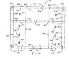
- FIG. 2is a plan view of the barrier in accordance with the embodiment of the present invention illustrated in FIG. 1 ;
- FIG. 3is a perspective view of the barrier illustrated in FIG. 2 , showing foldable end flaps of the barrier;
- FIG. 4is a bottom perspective view of the recessed electrical fixture assembly illustrated in FIG. 1 , showing the housing and electrical unit being mounted;
- FIG. 5is bottom perspective view of the recessed electrical fixture assembly illustrated in FIG. 1 , showing the housing and electrical unit mounted within the barrier and showing one remaining panel of the barrier being folded into place;
- FIG. 6is a plan view of a barrier in accordance with another embodiment of the present invention.
- a recessed electrical fixture assembly 10 in accordance with an embodiment of the present inventionis installed between first and second support members 12 and 14 , such as joists of a ceiling, and includes a barrier 16 that allows assembly 10 to be employed in ceilings or walls with insulation 18 in close proximity. More specifically, assembly 10 includes a housing 20 supporting an electrical unit 22 and barrier 16 spaces insulation 18 from housing 20 , thereby preventing overheating of electrical unit 22 and meeting UL requirements.
- Electrical unit 22can be a lighting unit or other electrical fixture, such as a fan. This is particularly useful when electrical unit 22 is a high wattage unit ihat dissipates significantly more heat than low wattage units or is a unit not rated for insulation contact.
- barrier 16includes foldable first, second and third panels 24 , 26 and 28 to facilitate mounting barrier 16 between first and second support members 12 and 14 .
- First and second support members 12 and 14are generally parallel and include first and second opposing inner surfaces 30 and 32 , respectively.
- Barrier 16is releasably coupled to inner surfaces 30 and 32 to mount barrier 16 between support members 12 and 14 .
- Barrier 16is substantially rectangular, generally flat when foldable panels 24 , 26 and 28 are unfolded, and includes opposite first and second surfaces 34 and 36 .
- Barrier 16can be any polygonal or circular shape as long as barrier 16 fits between support member 12 and 14 and spaces insulation 18 from housing 20 .
- First panel 24is defined between a first score line 38 extending across the width, i.e.
- Second panel 26is defined between first score line 38 and a second score line 42 that is substantially parallel to line 38 .
- Third panel 28is defined between second score line 42 and a second outer edge 44 opposite first edge 40 .
- First and third panels 24 and 28are foldable toward either first or second surface 34 and 36 with respect to second panel 26 .
- second panel 26is foldable toward either first or second surface 34 and 36 with respect to first and third panels 24 and 28 .
- first and third panels 24 and 28are substantially identical in length and width.
- Second panel 26 disposed between panels 24 and 28has generally twice the width of first and third panels 24 and 28 and substantially the same length.
- Each panel 24 , 26 and 28has a length which is transverse to the longitudinal length of barrier 16 and that is substantially the same as the distance between inner surfaces 30 and 32 of support members 12 and 14 , as seen in FIG. 1 .
- Barrier 16can be formed of heat insulating or non-heat insulating material, for example, corrugated plastic sheeting, PVC sheeting, corrugated fiberboard, fire rated sheeting, aluminum sheet and the like. Barrier 16 is preferably about 1 ⁇ 8 inch thick.
- Barrier 16forms an enclosure 46 when mounted between support members 12 and 14 .
- first, second and third panels 24 , 26 and 28form first, second and third sides 48 , 50 and 52 of enclosure 46 , respectively, and inner surfaces 30 and 32 of support members 12 and 14 form fourth and fifth sides 54 and 56 , respectively, at the ends of panels 24 , 26 and 28 .
- First and third sides 48 and 52are generally perpendicular to second side 50 .
- a sixth side 58opposite side 50 formed by second panel 26 , is substantially open to receive housing 20 and electrical unit 22 .
- First surface 34 of barrier 16forms the inner surface of enclosure 46 and second surface 36 forms the outer surface of enclosure 46 .
- Barrier 16can have more than three panels to form enclosure 46 , thereby eliminating inner surfaces 30 and 32 of support members 12 and 14 and the fourth and fifth sides 54 and 56 of enclosure 46 .
- Perforated knock-outs 60can be provided in first and third panels 24 and 26 to allow wiring 62 of electrical unit 22 to extend through and outside of enclosure 46 , as best seen in FIG. 5 .
- Instructional indicia(not shown) can also be provided on any of panels 24 , 26 and 28 .
- each of first, second and third panels 24 , 26 and 28 of barrier 16include first and second foldable end flaps 64 , 66 , 68 , 70 , 72 and 74 , respectively.
- Each end flap 64 , 66 , 68 , 70 , 72 and 74is defined by an end score line 76 , 78 , 80 , 82 , 84 and 86 disposed in respective panels 24 , 26 and 28 .
- End score lines 76 , 78 , 80 , 82 , 84 and 86are substantially transverse to first and second score lines 38 and 42 defining panels 24 , 26 and 28 .
- Each end flap 64 , 66 , 68 , 70 , 72 and 74is foldable about a respective end score line 76 , 78 , 80 , 82 , 84 and 86 towards either first or second surface 34 and 36 of barrier 16 with respect to panels 24 , 26 and 28 , as seen in FIG. 3 .
- End flaps 64 , 66 , 68 , 70 , 72 and 74are separated by cut lines 88 in barrier 16 extend substantially the width of respective panels 24 , 26 and 28 .
- housing 20is advantageously box shaped and is formed of a generally fire resistant material, such as plaster or wallboard including for example, sheet rock, plywood, asbestos cement sheets, gypsum plasterboard, laminated plastics, inturnscent material and the like.
- Housing 20includes an opening 90 that aligns with or corresponds to open side 58 of barrier enclosure 46 . As seen in FIGS.
- electrical unit 22is a lighting unit that is supported within housing 20 and has a reflector 92 supporting a lamp (not shown) that distributes electrical through opening 90 .
- An optional can 94can be included with electrical unit 22 for supporting reflector 92 and the lamp.
- Two support bars 96are coupled to opposite sides of housing 20 to mount housing 20 , with electrical unit 22 received therein, to support members 12 and 14 , as is known in the art.
- Housing 20can also be non-fire resistant or any housing not rated for insulation contact.
- Electrical unit 22can be any electrical fixture, such as a fan or exhaust unit.
- barrier 16is initially mounted between first and second support members 12 and 14 , and housing 20 supporting electrical unit 22 is subsequently mounted between support members 12 and 14 and substantially within enclosure 46 defined by barrier 16 .
- Insulation 18can then be disposed around barrier 16 outside of enclosure 46 , thereby spacing insulation 18 from housing 20 and preventing overheating of housing 20 and electrical unit 22 .
- Mounting barrier 16 between support members 12 and 14initially requires folding end flaps 68 and 70 toward first surface 34 of barrier 16 with respect to second panel 26 , as seen in FIG. 3 .
- Barrier 16is then positioned between support members 12 and 14 and end flaps 68 and 70 of second panel 26 are releasably coupled to first and second inner surfaces 30 and 32 of support members 12 and 14 , respectively, by any known releasable attachment, such as by stapling, nailing or using adhesive, including, for example, staples 93 shown in FIGS. 1 , 4 and 5 .
- Second panel 26is preferably positioned so that panel 26 is flush with side edges 98 transverse to inner surfaces 30 and 32 .
- first and third panels 24 and 28can then be folded towards first surface 34 of barrier 16 with respect to second panel 26 forming enclosure 46 (see FIG. 5 showing third panel 28 being folded into place).
- First and second end flaps 64 and 66are folded towards second surface 36 with respect to first panel 24 and first and second end flaps 72 and 74 are folded towards second surface 36 with respect to third panel 28 .
- Housing 20 with electrical unit 22is then inserted through open side 58 of enclosure 46 and mounted to inner surfaces 30 and 32 of support members 12 and 14 via support bars 96 by any known attachment, such as staples or nails.
- end flaps 64 , 66 , 72 and 74 of first and third panels 24 and 28are releasably coupled to inner surfaces 30 and 32 of support members 12 and 14 in the same manner as flaps 68 and 70 .
- End flaps 68 and 70 of second panel 26extend inwardly with respect to enclosure 46 and end flaps 64 , 66 , 72 and 74 extend outwardly opposite flaps 68 and 70 , as best seen in FIGS. 4 and 5 .
- end flaps 64 , 66 , 68 , 70 , 72 and 74can fold or extend either inwardly or outwardly with respect to enclosure 46 .
- barrier 16can be self-supporting, that is without being coupled to support members 12 and 14 .
- Panels 24 , 26 and 28 of barrier 16are spaced about 3 inches or more from housing 20 , allowing insulation 18 to be placed around assembly 10 , specifically around barrier 16 , with insulation 18 being sufficiently spaced from housing 20 and electrical unit 22 to prevent overheating.
- a conventional thermal sensor (not shown) of electrical unit 22set to UL requirements for heat dissipation of recessed electrical units, will switch electrical unit 22 off if the heat dissipation exceeds UL standards.
- Barrier 16maintains appropriate heat levels, particularly for higher wattage electrical units, by forming and maintaining the space between housing 20 and insulation 18 . Without the space between barrier 16 and housing 20 , insulation 18 would overheat housing 20 and electrical unit 22 causing the thermal sensor to deactivate electrical unit 22 .
- housing 20 and its electrical unit 22can be installed in ceilings or walls with insulation instead of without insulation and avoid overheating and deactivation by the thermal sensor.
- a barrier 116 in accordance with another embodiment of the present inventionis substantially similar to barrier 16 of the first embodiment of fire resistant recessed electrical fixture assembly 10 , except for barrier 116 is adjustable to the distance between first and second support members 12 and 14 and to the size of housing 20 supporting electrical unit 22 . More specifically, barrier 116 includes first, second and third tear away sections 200 , 202 and 204 , that allow the installer to adjust the length and width of barrier 116 .
- barrier 116includes first, second and third panels 124 , 126 and 128 defined by first and second score lines 138 and 142 .
- Each panel 124 , 126 and 128has first and second foldable end flaps 164 , 166 , 168 , 170 , 172 and 174 , respectively.
- Each end flap 164 , 166 , 168 , 170 , 172 and 174is defined by an end score line 176 , 178 , 180 , 182 , 184 and 186 which are separated by cut lines 188 .
- End score lines 176 , 178 , 180 , 182 , 184 and 186are substantially transverse to first and second score lines 138 and 142 defining panels 124 , 126 and 128 .
- First tear away section 200extends from second end flaps 166 , 170 , and 174 of panels 124 , 126 and 128 , thereby increasing the length of first, second and third panels 124 , 126 and 128 .
- a first perforated line 206is disposed between second end flaps 166 , 170 and 174 and first tear away section 200 .
- First perforated line 206is generally parallel to end score lines 176 , 178 , 180 , 182 , 184 and 186 .
- First and second score lines 138 and 142extend into first tear away section 200 , allowing first tear away section 200 to fold as first, second and third panels 124 , 126 and 128 are folded.
- First tear away section 200is provided with first, second and third foldable end flaps 208 , 210 and 212 extending from section 200 opposite first perforated line 206 .
- End flaps 208 , 210 and 212are foldable about respective end score lines 214 , 216 and 218 and are separated by cut lines 220 .
- First tear away section 200can also include knock-outs 222 aligned with knock-outs 160 of panels 124 and 128 .
- Second and third tear away sections 202 and 204extend from a first outer edge 140 of first panel 124 and a second outer edge 144 of third panel 128 , respectively, thereby increasing the width of panels 124 and 128 . Second and third tear away sections 202 and 204 also extend from opposite edges 224 and 226 of first tear away section 200 . Second and third perforated lines 228 and 230 are disposed between first and third panels 124 and 128 and second and third tear away sections 202 and 204 and between edges 224 and 226 of first tear away section 200 and second and third tear away sections 202 and 204 .
- End score line 176 of first panel 124 and end score line 184 of third panel 128extend into second and third sections 202 and 204 , respectively, allowing second and third sections 202 and 204 to fold when end flaps 164 and 172 are folded.
- end score line 178 of first panel 124 and end score line 186 of third panel 128extend into second and third sections 202 and; 204 , respectively, allowing second and third sections 202 and 204 to fold when end flaps 166 and 174 are folded.
- first perforated line 206 of first section 200extends into second and third sections 202 and 204 and end score lines 214 and 218 of first section 200 extend into second and third sections 202 and 204 , respectively.
- Barrier 116is mounted between first and second support members 12 and 14 in the same manner as described above with respect to barrier 16 of the first embodiment, except first, second and third tear away sections 200 , 202 and 204 can be removed to adjust the width and length of barrier 116 depending on the size of housing 20 and electrical unit 22 and the distance between first and second support members 12 and 14 . If for example a larger barrier is required, that is to accommodate a larger housing 20 , larger support members and wider spaced support members 12 and 14 , then barrier 116 can be mounted without removing sections 200 , 202 and 204 .
- end flaps 208 , 210 and 212 of first section 200would be releasably coupled to first inner surface 30 of first support member 12 and end flaps 164 , 168 and 172 of panels 124 , 126 and 128 , respectively, would be releasably coupled to second inner surface 32 of second support member to form enclosure 46 around housing 20 .
- second and third tear away sections 202 and 204can be removed to adjust the length of barrier 116 but not the width with end flaps by separating second third sections 202 and 204 at second and third perforated lines 228 and 230 .
- first tear way section 200can be removed by separating section 200 from end flaps 166 , 170 and 174 at first perforated line 206 to adjust the width of barrier 116 , that is transverse to longitudinal length of barrier 116 , but not adjusting the length of barrier 116 .
- first and second end flaps 164 , 166 , 168 , 170 , 172 and 174are releasably coupled to inner surfaces 30 and 32 of support members 12 and 14 as described above with respect to barrier 16 .
- Portions 232 and 234 of second and third tear away sections 202 and 204 adjacent first section 200would also be removed, leaving the width of barrier 116 , substantially equal to barrier 16 of the first embodiment.
- barrier 116would be longer than barrier 16 by portions 236 and 238 of second and third sections 202 and 204 which remain adjacent first and third panels 124 and 128 of barrier 116 .
- First, second and third tear away sections 200 , 202 and 206can be removed individually or in any combination to provide the appropriate adjustment for the size of housing 20 and electrical unit 22 , the size of support members 12 and 14 and the distance between support members 12 and 14 .
Landscapes
- Engineering & Computer Science (AREA)
- Architecture (AREA)
- Civil Engineering (AREA)
- Structural Engineering (AREA)
- Building Environments (AREA)
Abstract
Description
Claims (36)
Priority Applications (1)
| Application Number | Priority Date | Filing Date | Title |
|---|---|---|---|
| US10/743,543US6872885B1 (en) | 2003-12-23 | 2003-12-23 | Recessed electrical fixture assembly with insulation barrier and method of using the same |
Applications Claiming Priority (1)
| Application Number | Priority Date | Filing Date | Title |
|---|---|---|---|
| US10/743,543US6872885B1 (en) | 2003-12-23 | 2003-12-23 | Recessed electrical fixture assembly with insulation barrier and method of using the same |
Publications (1)
| Publication Number | Publication Date |
|---|---|
| US6872885B1true US6872885B1 (en) | 2005-03-29 |
Family
ID=34314228
Family Applications (1)
| Application Number | Title | Priority Date | Filing Date |
|---|---|---|---|
| US10/743,543Expired - LifetimeUS6872885B1 (en) | 2003-12-23 | 2003-12-23 | Recessed electrical fixture assembly with insulation barrier and method of using the same |
Country Status (1)
| Country | Link |
|---|---|
| US (1) | US6872885B1 (en) |
Cited By (18)
| Publication number | Priority date | Publication date | Assignee | Title |
|---|---|---|---|---|
| US20070164178A1 (en)* | 2006-01-17 | 2007-07-19 | Beilstein Christine D | Mounting receptacle with interchangeable hub |
| US20070204536A1 (en)* | 2006-03-02 | 2007-09-06 | Latanision David A | Prefabricated fixture protection cover and assembly and method of use thereof |
| US20080010907A1 (en)* | 2006-05-03 | 2008-01-17 | Moench John P | Recessed ceiling fixture enclosure |
| USD570802S1 (en)* | 2006-04-04 | 2008-06-10 | Sanford, L.P. | Electronics hub |
| USD624688S1 (en)* | 2009-01-12 | 2010-09-28 | Aurora Lighting, Inc. | Fire rated downlight housing |
| USD629556S1 (en) | 2009-09-21 | 2010-12-21 | Owens Corning Intellectual Capital, Llc | Lighting enclosure |
| US20110036034A1 (en)* | 2008-02-04 | 2011-02-17 | Raymond Robinson | Insulation apparatus and method |
| US20110069498A1 (en)* | 2009-09-21 | 2011-03-24 | Alter Harry A | Enclosure for a recessed light in an attic |
| USD655436S1 (en) | 2010-04-09 | 2012-03-06 | Aurora Lighting, Inc. | Fire rated downlight housing |
| US20130155694A1 (en)* | 2010-05-27 | 2013-06-20 | David S. Hanacek | Recessed Lighting Enclosure and Insulation Barrier |
| US20140301087A1 (en)* | 2013-04-05 | 2014-10-09 | Grzegorz Wronski | Housings and Related Components for Luminaires |
| US9335032B2 (en) | 2010-08-18 | 2016-05-10 | Thermastop, Llc | Insulated recessed light can cover |
| US20180010335A1 (en)* | 2005-07-12 | 2018-01-11 | Spirit Acoustics Inc. | Acoustic systems for lighting in suspended ceilings |
| US10001270B2 (en) | 2013-04-05 | 2018-06-19 | Cooper Technologies Company | Housings and related components for luminaires |
| US10651638B1 (en)* | 2016-05-11 | 2020-05-12 | Lucas Tucker Schad | Electrical junction box shell apparatus with enhanced insulation |
| US11015785B1 (en) | 2020-02-19 | 2021-05-25 | Abl Ip Holding Llc | Light fixture system with continuous fire barrier |
| US11118769B1 (en) | 2020-02-20 | 2021-09-14 | Abl Ip Holding Llc | Rotating and tilting lighting fixtures |
| USD971492S1 (en) | 2019-11-08 | 2022-11-29 | Abl Ip Holding Llc | Downlight reflector |
Citations (37)
| Publication number | Priority date | Publication date | Assignee | Title |
|---|---|---|---|---|
| US3104833A (en) | 1963-09-24 | Recessed lighting fixture | ||
| US4093818A (en) | 1974-12-20 | 1978-06-06 | Dufaylite Developments Limited | Fire-protective cellular service ducting |
| US4210070A (en) | 1978-03-06 | 1980-07-01 | Dayus Barry R | Ceiling fixture with thermal protection |
| US4237671A (en) | 1978-07-24 | 1980-12-09 | Insulation Sales Company | Insulation barrier for recessed light fixtures |
| US4276332A (en) | 1979-11-06 | 1981-06-30 | Castle George K | Fire proof cable tray enclosure |
| US4375142A (en) | 1978-03-14 | 1983-03-01 | Mcdonald Gerald L | Guard for isolating recessed ceiling lights from combustible insulation |
| US4400673A (en) | 1981-12-21 | 1983-08-23 | Kiddo Consumer Durables Corporation | Thermal switch housing |
| US4400766A (en) | 1981-01-05 | 1983-08-23 | Low Energy Homes, Inc. | Insulation damming device |
| US4574454A (en) | 1984-01-14 | 1986-03-11 | Chubb & Son's Lock And Safe Company Limited | Method of constructing fire resistant enclosures |
| US4751624A (en) | 1987-12-14 | 1988-06-14 | Lightolier Incoporated | Safety ceiling fixture with heat sensor |
| US4930054A (en) | 1988-12-09 | 1990-05-29 | Nutone, Inc. | Dual cone recessed lighting fixture |
| US5034859A (en) | 1989-12-26 | 1991-07-23 | Gte Products Corporation | Recessed fluorescent luminaire housing |
| US5222800A (en) | 1992-01-28 | 1993-06-29 | The Genlyte Group Incorporated | Recessed lighting fixture |
| US5351448A (en) | 1993-04-19 | 1994-10-04 | Balco, Inc. | Fire barrier |
| US5373431A (en) | 1993-08-31 | 1994-12-13 | Cooper Industries, Inc. | Ring/baffle element for a trim of a recessed lighting fixture |
| US5404687A (en) | 1991-04-24 | 1995-04-11 | Avco Corporation | Intumescent fireproofing panel system |
| US5457617A (en) | 1993-06-17 | 1995-10-10 | Lightolier Division Of The Genlyte Group Incorporated | Sloped recessed lighting fixture |
| US5470471A (en) | 1993-05-14 | 1995-11-28 | Ingersoll-Rand Company | Anti-rewet deck for press rolls |
| US5548499A (en) | 1994-08-19 | 1996-08-20 | Amp Plus, Inc. | Light fixture for recess in sloped ceiling |
| US5546711A (en) | 1995-05-26 | 1996-08-20 | Heller; Paul S. | Base isolator fire barrier system |
| US5562343A (en) | 1994-10-14 | 1996-10-08 | Lightolier Division Of The Genlyte Group Incorporated | Multifunctional recessed lighting fixture |
| US5567041A (en) | 1995-08-14 | 1996-10-22 | Slocum; Karl | Self supporting recessed ceiling fixture |
| US5588737A (en) | 1994-11-10 | 1996-12-31 | Thomas Industries, Inc. | Modular recessed lighting system |
| US5823664A (en) | 1996-05-29 | 1998-10-20 | Hubbell Incorporated | Recessed lighting fixture |
| US6079856A (en) | 1998-12-17 | 2000-06-27 | Prestier; Douglas J. | Light fixture thermal insulator |
| US6082878A (en) | 1998-02-03 | 2000-07-04 | Cooper Industries, Inc. | Fully rotatable recessed light fixture with movable stop and adjustable length bar hanger |
| US6105334A (en) | 1997-09-16 | 2000-08-22 | Logic Construction Systems, L.L.C. | Fire resistant lighting enclosure |
| US6123435A (en) | 1998-06-03 | 2000-09-26 | Hubbell Incorporated | Sheet metal housing for an HID luminaire |
| US6123438A (en) | 1998-08-24 | 2000-09-26 | Nsi Enterprises, Inc. | Insulation shield for recessed downlighting fixtures |
| US6176599B1 (en) | 1999-09-17 | 2001-01-23 | Fred Farzen | Insulated ceiling type low voltage recessed housing |
| US6218613B1 (en)* | 1998-08-19 | 2001-04-17 | Leviton Manufacturing Co., Inc. | Divided standard device inch box |
| US6239365B1 (en)* | 1999-05-20 | 2001-05-29 | Mcevers Douglas W. | Sealable electrical outlet enclosure |
| US6286980B1 (en) | 1999-06-29 | 2001-09-11 | Donald L. Meyer | Recessed light protection cover |
| US6357891B1 (en) | 2000-03-08 | 2002-03-19 | Progress Lighting | Fire assembly for recessed light fixtures |
| US20020157324A1 (en) | 2000-03-08 | 2002-10-31 | Progress Lighting | Fire assembly for recessed electrical fixtures |
| US6474846B1 (en) | 1999-03-05 | 2002-11-05 | Victor Kelmelis | Flush trim collar lighting system |
| US6657123B2 (en)* | 2001-10-01 | 2003-12-02 | Tampa Armature Works, Inc. | Power distribution cabinet |
- 2003
- 2003-12-23USUS10/743,543patent/US6872885B1/ennot_activeExpired - Lifetime
Patent Citations (37)
| Publication number | Priority date | Publication date | Assignee | Title |
|---|---|---|---|---|
| US3104833A (en) | 1963-09-24 | Recessed lighting fixture | ||
| US4093818A (en) | 1974-12-20 | 1978-06-06 | Dufaylite Developments Limited | Fire-protective cellular service ducting |
| US4210070A (en) | 1978-03-06 | 1980-07-01 | Dayus Barry R | Ceiling fixture with thermal protection |
| US4375142A (en) | 1978-03-14 | 1983-03-01 | Mcdonald Gerald L | Guard for isolating recessed ceiling lights from combustible insulation |
| US4237671A (en) | 1978-07-24 | 1980-12-09 | Insulation Sales Company | Insulation barrier for recessed light fixtures |
| US4276332A (en) | 1979-11-06 | 1981-06-30 | Castle George K | Fire proof cable tray enclosure |
| US4400766A (en) | 1981-01-05 | 1983-08-23 | Low Energy Homes, Inc. | Insulation damming device |
| US4400673A (en) | 1981-12-21 | 1983-08-23 | Kiddo Consumer Durables Corporation | Thermal switch housing |
| US4574454A (en) | 1984-01-14 | 1986-03-11 | Chubb & Son's Lock And Safe Company Limited | Method of constructing fire resistant enclosures |
| US4751624A (en) | 1987-12-14 | 1988-06-14 | Lightolier Incoporated | Safety ceiling fixture with heat sensor |
| US4930054A (en) | 1988-12-09 | 1990-05-29 | Nutone, Inc. | Dual cone recessed lighting fixture |
| US5034859A (en) | 1989-12-26 | 1991-07-23 | Gte Products Corporation | Recessed fluorescent luminaire housing |
| US5404687A (en) | 1991-04-24 | 1995-04-11 | Avco Corporation | Intumescent fireproofing panel system |
| US5222800A (en) | 1992-01-28 | 1993-06-29 | The Genlyte Group Incorporated | Recessed lighting fixture |
| US5351448A (en) | 1993-04-19 | 1994-10-04 | Balco, Inc. | Fire barrier |
| US5470471A (en) | 1993-05-14 | 1995-11-28 | Ingersoll-Rand Company | Anti-rewet deck for press rolls |
| US5457617A (en) | 1993-06-17 | 1995-10-10 | Lightolier Division Of The Genlyte Group Incorporated | Sloped recessed lighting fixture |
| US5373431A (en) | 1993-08-31 | 1994-12-13 | Cooper Industries, Inc. | Ring/baffle element for a trim of a recessed lighting fixture |
| US5548499A (en) | 1994-08-19 | 1996-08-20 | Amp Plus, Inc. | Light fixture for recess in sloped ceiling |
| US5562343A (en) | 1994-10-14 | 1996-10-08 | Lightolier Division Of The Genlyte Group Incorporated | Multifunctional recessed lighting fixture |
| US5588737A (en) | 1994-11-10 | 1996-12-31 | Thomas Industries, Inc. | Modular recessed lighting system |
| US5546711A (en) | 1995-05-26 | 1996-08-20 | Heller; Paul S. | Base isolator fire barrier system |
| US5567041A (en) | 1995-08-14 | 1996-10-22 | Slocum; Karl | Self supporting recessed ceiling fixture |
| US5823664A (en) | 1996-05-29 | 1998-10-20 | Hubbell Incorporated | Recessed lighting fixture |
| US6105334A (en) | 1997-09-16 | 2000-08-22 | Logic Construction Systems, L.L.C. | Fire resistant lighting enclosure |
| US6082878A (en) | 1998-02-03 | 2000-07-04 | Cooper Industries, Inc. | Fully rotatable recessed light fixture with movable stop and adjustable length bar hanger |
| US6123435A (en) | 1998-06-03 | 2000-09-26 | Hubbell Incorporated | Sheet metal housing for an HID luminaire |
| US6218613B1 (en)* | 1998-08-19 | 2001-04-17 | Leviton Manufacturing Co., Inc. | Divided standard device inch box |
| US6123438A (en) | 1998-08-24 | 2000-09-26 | Nsi Enterprises, Inc. | Insulation shield for recessed downlighting fixtures |
| US6079856A (en) | 1998-12-17 | 2000-06-27 | Prestier; Douglas J. | Light fixture thermal insulator |
| US6474846B1 (en) | 1999-03-05 | 2002-11-05 | Victor Kelmelis | Flush trim collar lighting system |
| US6239365B1 (en)* | 1999-05-20 | 2001-05-29 | Mcevers Douglas W. | Sealable electrical outlet enclosure |
| US6286980B1 (en) | 1999-06-29 | 2001-09-11 | Donald L. Meyer | Recessed light protection cover |
| US6176599B1 (en) | 1999-09-17 | 2001-01-23 | Fred Farzen | Insulated ceiling type low voltage recessed housing |
| US6357891B1 (en) | 2000-03-08 | 2002-03-19 | Progress Lighting | Fire assembly for recessed light fixtures |
| US20020157324A1 (en) | 2000-03-08 | 2002-10-31 | Progress Lighting | Fire assembly for recessed electrical fixtures |
| US6657123B2 (en)* | 2001-10-01 | 2003-12-02 | Tampa Armature Works, Inc. | Power distribution cabinet |
Non-Patent Citations (3)
| Title |
|---|
| Progress Lighting; firebox(R) The Recessed Downlighting Solution for Fire Rated Ceilings; Recessed Lighting, Apr. 2003, p. 36, no date. |
| Progress Lighting; P8012-Kit, retrofit kit for P8012 decorative recessed trims to fit into Juno and Halo housings, Recessed Lighting, Apr. 2003. p. 60, no date. |
| Progress Lighting; P8585-01 Goof Ring, O.D. 8-7/8'', for use with any recessed trim with a 7-3/4'' O.D., Recessed Lighting, Apr. 2003, p. 60, no date. |
Cited By (28)
| Publication number | Priority date | Publication date | Assignee | Title |
|---|---|---|---|---|
| US20180010335A1 (en)* | 2005-07-12 | 2018-01-11 | Spirit Acoustics Inc. | Acoustic systems for lighting in suspended ceilings |
| US11142907B2 (en) | 2005-07-12 | 2021-10-12 | Spirit Acoustics Inc. | Acoustic systems for lighting in suspended ceilings |
| US10184248B2 (en)* | 2005-07-12 | 2019-01-22 | Spirit Acoustics Inc. | Acoustic systems for lighting in suspended ceilings |
| US20070164178A1 (en)* | 2006-01-17 | 2007-07-19 | Beilstein Christine D | Mounting receptacle with interchangeable hub |
| US20070204536A1 (en)* | 2006-03-02 | 2007-09-06 | Latanision David A | Prefabricated fixture protection cover and assembly and method of use thereof |
| US7627999B2 (en)* | 2006-03-02 | 2009-12-08 | Specialty Products & Insulation | Prefabricated fixture protection cover and assembly and method of use thereof |
| USD570802S1 (en)* | 2006-04-04 | 2008-06-10 | Sanford, L.P. | Electronics hub |
| USD576118S1 (en) | 2006-04-04 | 2008-09-02 | Sanford, L.P. | Electronics hub |
| US20080010907A1 (en)* | 2006-05-03 | 2008-01-17 | Moench John P | Recessed ceiling fixture enclosure |
| US20100238670A1 (en)* | 2006-05-03 | 2010-09-23 | Moench John P | Recessed ceiling fixture enclosure |
| US20110036034A1 (en)* | 2008-02-04 | 2011-02-17 | Raymond Robinson | Insulation apparatus and method |
| USD624688S1 (en)* | 2009-01-12 | 2010-09-28 | Aurora Lighting, Inc. | Fire rated downlight housing |
| USD641909S1 (en) | 2009-01-12 | 2011-07-19 | Aurora Lighting, Inc. | Fire rated downlight housing |
| US8337056B2 (en) | 2009-09-21 | 2012-12-25 | Owens Corning Intellectual Capital, Llc | Enclosure for a recessed light in an attic |
| USD629556S1 (en) | 2009-09-21 | 2010-12-21 | Owens Corning Intellectual Capital, Llc | Lighting enclosure |
| US20110069498A1 (en)* | 2009-09-21 | 2011-03-24 | Alter Harry A | Enclosure for a recessed light in an attic |
| USD655436S1 (en) | 2010-04-09 | 2012-03-06 | Aurora Lighting, Inc. | Fire rated downlight housing |
| US20130155694A1 (en)* | 2010-05-27 | 2013-06-20 | David S. Hanacek | Recessed Lighting Enclosure and Insulation Barrier |
| US9335032B2 (en) | 2010-08-18 | 2016-05-10 | Thermastop, Llc | Insulated recessed light can cover |
| US10006618B2 (en) | 2013-04-05 | 2018-06-26 | Cooper Technologies Company | Housings and related components for luminaires |
| US10001270B2 (en) | 2013-04-05 | 2018-06-19 | Cooper Technologies Company | Housings and related components for luminaires |
| US9062837B2 (en)* | 2013-04-05 | 2015-06-23 | Cooper Technologies Company | Housings and related components for luminaires |
| US10684003B2 (en) | 2013-04-05 | 2020-06-16 | Eaton Intelligent Power Limited | Housings and related components for luminaires |
| US20140301087A1 (en)* | 2013-04-05 | 2014-10-09 | Grzegorz Wronski | Housings and Related Components for Luminaires |
| US10651638B1 (en)* | 2016-05-11 | 2020-05-12 | Lucas Tucker Schad | Electrical junction box shell apparatus with enhanced insulation |
| USD971492S1 (en) | 2019-11-08 | 2022-11-29 | Abl Ip Holding Llc | Downlight reflector |
| US11015785B1 (en) | 2020-02-19 | 2021-05-25 | Abl Ip Holding Llc | Light fixture system with continuous fire barrier |
| US11118769B1 (en) | 2020-02-20 | 2021-09-14 | Abl Ip Holding Llc | Rotating and tilting lighting fixtures |
Similar Documents
| Publication | Publication Date | Title |
|---|---|---|
| US6872885B1 (en) | Recessed electrical fixture assembly with insulation barrier and method of using the same | |
| US10634298B2 (en) | Bar hanger system for recessed fixtures | |
| US7651238B2 (en) | Fireproof trim and insulated lighting assembly | |
| US6838618B2 (en) | Fire assembly for recessed electrical fixtures | |
| US7771094B2 (en) | Mounting bracket for electrical junction box, luminaire or the like | |
| US9627867B2 (en) | Mounting brace assembly for mounting an electrical box | |
| US6369322B1 (en) | Electric box extender and supplemental parts | |
| US20080022616A1 (en) | H-shaped boot-to-register cover mounting adapter | |
| US9583926B2 (en) | Hanger bar | |
| US20170005460A1 (en) | Wall Clamping Junction Box | |
| CA2312160C (en) | Recessed light protection cover | |
| US6307154B1 (en) | Electric box extender and supplemental parts | |
| JPH0628908A (en) | Illumination equipment and its manufacture | |
| US20090002978A1 (en) | Linear lighting system having a spinal structure and an optical system separately installable thereon | |
| US6825414B2 (en) | Exterior mounting block for electrical fixtures | |
| WO2009126959A2 (en) | Lighting system for an architectural surface structure | |
| US6204447B1 (en) | Electric box extender and supplemental parts | |
| US7627999B2 (en) | Prefabricated fixture protection cover and assembly and method of use thereof | |
| US6180879B1 (en) | Electric box extender and supplemental parts | |
| US20120134162A1 (en) | Recessed Lighting Enclosure and Insulation Barrier | |
| US20160049778A1 (en) | Recessed fixture enclosure | |
| US9335032B2 (en) | Insulated recessed light can cover | |
| US20050034407A1 (en) | Support frame for duct | |
| WO2005124054A1 (en) | A device and method for flush mounting air duct grates, electrical switch plates, electrical receptacle plates, electrical light fixtures and other drywall aperture covers on drywall surfaces using drywall bead | |
| US10651638B1 (en) | Electrical junction box shell apparatus with enhanced insulation |
Legal Events
| Date | Code | Title | Description |
|---|---|---|---|
| AS | Assignment | Owner name:HUBBELL INCORPORATED, CONNECTICUT Free format text:ASSIGNMENT OF ASSIGNORS INTEREST;ASSIGNOR:NEWBOLD, RONALD C., JR.;REEL/FRAME:015247/0145 Effective date:20040413 | |
| STCF | Information on status: patent grant | Free format text:PATENTED CASE | |
| FPAY | Fee payment | Year of fee payment:4 | |
| FPAY | Fee payment | Year of fee payment:8 | |
| FPAY | Fee payment | Year of fee payment:12 | |
| AS | Assignment | Owner name:PROGRESS LIGHTING, LLC, SOUTH CAROLINA Free format text:ASSIGNMENT OF ASSIGNORS INTEREST;ASSIGNOR:HUBBELL INCORPORATED;REEL/FRAME:065572/0891 Effective date:20231110 | |
| AS | Assignment | Owner name:WELLS FARGO BANK, NATIONAL ASSOCIATION, ARIZONA Free format text:SECURITY INTEREST;ASSIGNOR:PROGRESS LIGHTING, LLC;REEL/FRAME:066433/0314 Effective date:20240209 Owner name:TCW ASSET MANAGEMENT COMPANY LLC, MASSACHUSETTS Free format text:SECURITY INTEREST;ASSIGNOR:PROGRESS LIGHTING, LLC;REEL/FRAME:066429/0529 Effective date:20240209 |