US6872358B2 - Test strip dispenser - Google Patents
Test strip dispenserDownload PDFInfo
- Publication number
- US6872358B2 US6872358B2US10/052,212US5221202AUS6872358B2US 6872358 B2US6872358 B2US 6872358B2US 5221202 AUS5221202 AUS 5221202AUS 6872358 B2US6872358 B2US 6872358B2
- Authority
- US
- United States
- Prior art keywords
- test strip
- base
- test strips
- test
- cover
- Prior art date
- Legal status (The legal status is an assumption and is not a legal conclusion. Google has not performed a legal analysis and makes no representation as to the accuracy of the status listed.)
- Expired - Lifetime, expires
Links
Images


Classifications
- G—PHYSICS
- G01—MEASURING; TESTING
- G01N—INVESTIGATING OR ANALYSING MATERIALS BY DETERMINING THEIR CHEMICAL OR PHYSICAL PROPERTIES
- G01N1/00—Sampling; Preparing specimens for investigation
- G01N1/02—Devices for withdrawing samples
- G01N1/04—Devices for withdrawing samples in the solid state, e.g. by cutting
- G—PHYSICS
- G01—MEASURING; TESTING
- G01N—INVESTIGATING OR ANALYSING MATERIALS BY DETERMINING THEIR CHEMICAL OR PHYSICAL PROPERTIES
- G01N33/00—Investigating or analysing materials by specific methods not covered by groups G01N1/00 - G01N31/00
- G01N33/48—Biological material, e.g. blood, urine; Haemocytometers
- G01N33/483—Physical analysis of biological material
- G01N33/487—Physical analysis of biological material of liquid biological material
- G01N33/4875—Details of handling test elements, e.g. dispensing or storage, not specific to a particular test method
- G01N33/48757—Test elements dispensed from a stack
- B—PERFORMING OPERATIONS; TRANSPORTING
- B01—PHYSICAL OR CHEMICAL PROCESSES OR APPARATUS IN GENERAL
- B01L—CHEMICAL OR PHYSICAL LABORATORY APPARATUS FOR GENERAL USE
- B01L99/00—Subject matter not provided for in other groups of this subclass
- G—PHYSICS
- G01—MEASURING; TESTING
- G01N—INVESTIGATING OR ANALYSING MATERIALS BY DETERMINING THEIR CHEMICAL OR PHYSICAL PROPERTIES
- G01N35/00—Automatic analysis not limited to methods or materials provided for in any single one of groups G01N1/00 - G01N33/00; Handling materials therefor
- G01N35/00029—Automatic analysis not limited to methods or materials provided for in any single one of groups G01N1/00 - G01N33/00; Handling materials therefor provided with flat sample substrates, e.g. slides
- G01N2035/00089—Magazines
- Y—GENERAL TAGGING OF NEW TECHNOLOGICAL DEVELOPMENTS; GENERAL TAGGING OF CROSS-SECTIONAL TECHNOLOGIES SPANNING OVER SEVERAL SECTIONS OF THE IPC; TECHNICAL SUBJECTS COVERED BY FORMER USPC CROSS-REFERENCE ART COLLECTIONS [XRACs] AND DIGESTS
- Y10—TECHNICAL SUBJECTS COVERED BY FORMER USPC
- Y10T—TECHNICAL SUBJECTS COVERED BY FORMER US CLASSIFICATION
- Y10T436/00—Chemistry: analytical and immunological testing
- Y10T436/11—Automated chemical analysis
Definitions
- the field of this inventionis test strip dispensers.
- Analyte concentration determination in physiological samplesis of ever increasing importance to today's society. Such assays find use in a variety of application settings, including clinical laboratory testing, home testing, etc., where the results of such testing play a prominent role in the diagnosis and management of a variety of disease conditions. Analytes of interest include glucose for diabetes management, cholesterol for monitoring cardiovascular conditions, and the like. In response to this growing importance of analyte concentration determination, a variety of analyte concentration determination protocols and devices for both clinical and home testing have been developed.
- test stripBefore testing can begin, an individual seeking to determine the presence and/or concentration of an analyte in a physiological sample must first obtain a test strip, apply a sample thereto and obtain the results, either manually or automatically with a meter or the like.
- obtaining a test strip to begin the procedureis not without difficulty.
- diabeticstypically have visual and/or dexterity problems, thus making the selection of a single test strip, which usually has a length of about 50 mm and a width of about 7 mm, from a plurality of such test strips difficult.
- a plurality of test stripsare stored in a relatively large vessel, i.e., a vessel large enough to hold a plurality of test strips and to completely encompass the test strips inside so as to protect the test strips from light, humidity, and other environmental contaminants including oils and the like from a user's hands, where such protection is necessary to insure the precision, accuracy and overall integrity of the test result.
- An exemplary embodiment of a subject test strip storage vesselis shown in FIG. 1 .
- an individualhas two options for removing a test strip. In one option, an individual may simply turn the vessel upside down to pour a test strip out.
- test strips stored inside the vesselmay quickly spill onto out and becomes contaminated.
- an individualplaces a finger inside the vessel to try to grasp a single test strip amongst a plurality of test strips without damaging any of the strips in the process.
- a methodoftentimes results in the user inadvertently contacting portions of the test strip that should not be touched, such as testing or reaction areas (i.e., areas on the strip having testing reagents, etc.) and the like, where such contact can impart contaminants and cause erroneous testing results.
- other test stripsmay be inadvertently contacted resulting in erroneous testing results of those test strips as well.
- the vesselmust have a suitable shape and sized large enough to accommodate at least one finger therein, for easy removal of a test strip.
- the vesselmust enable an individual, i.e., an individual who may be visually and dextrally impaired, to retrieve a test strip from amongst a plurality of test strips without damaging or contaminating any of such test strips.
- the vesselwhile maintaining a size large enough to serve its functions, must be small enough to enable portability of the vessel so that an individual may easily carry the vessel at all times to accommodate testing during the course of a day.
- conventional vesselstypically have a circular cross-sectional shape to accommodate insertion of at least one finger therein, have a height of about 60 mm and a diameter of about 25 mm and are commercially sold with about 25 test strips retained therein.
- size and shapecreates a great amount of unused space inside the vessel and minimizes the portability of the vessel.
- the vesselsare larger than necessary to simply hold the test strips, thus increasing costs and decreasing portability.
- U.S. Pat. No. 4,911,344 to Kahlerdiscloses a strip dispenser box capable of dispensing a single test strip from a stack of test strips that does not require the user to insert a finger inside a vessel to retrieve a test strip. Rather, the '344 patent discloses a cap assembly with a strip feeder mechanism mounted to a housing having a magazine capable of holding a stack of test strips. The cap has a slot therein and a slide bar assembly slideably mounted in the slot for moving a test strip out of the dispenser, more particularly out of a gasket-sealed opening positioned on the cap assembly.
- the device disclosed in the '344 patentsuffers from certain disadvantages.
- the strip dispenser of the '344 patentfails to maintain a completely moisture free environment. Specifically, at least two areas of the dispenser permit moisture to enter the housing and thus contact the test strips therein.
- the first area which fails to provide a moisture free sealis the slot/slide bar assembly area.
- the slide baris made of a cross shaped base member slideably positioned on the inner surface of the cap body and a finger grip which extends upward through the slot of the cap assembly. In operation, the finger grip is driven forward by the action of the thumb of the user and it carries a test strip out an opening of the cap assembly.
- the preferred material of the dispenseris polyethylene plastic.
- both the cap assembly (the slot area) and the slide barare made of polyethylene plastic. It will be apparent to one of skill in the art that such an assembly of two contacting polyethylene plastic surfaces cannot provide an adequate barrier to moisture.
- the second area which fails to provide a moisture free sealis the opening through which a test strip is removed from the dispenser, even though a seal strip or gasket extends about ⁇ fraction (1/32) ⁇ of an inch into the dispenser and covers the opening thereto.
- a gasket or the likeis attached on a first side to the cap assembly and unattached on its other sides to allow a test strip to be pushed therethrough. It will similarly be apparent to one of skill in the art that such a seal cannot provide a barrier to moisture.
- the efficiency of a seal between two surfaces touching each otherdepends on the surface materials and the pressure exerted by one surface to the other or, in other words, the normal or perpendicular forces holding the surfaces together.
- the seal between the slide bar surface and the mating surface of the opening through which it extendsis not efficient because attempts to form a perfect seal or increase the sealing ability by making the surfaces flatter or more resilient will increase the coefficient of friction between the two surfaces, making it more difficult to slide or move the bar in relation to the body of the device, as needed to dispense a test strip. Increasing the normal force between the two surfaces to form a perfect seal or increase the sealing ability will also increase the force needed to slide the bar.
- any attempt to increase the load to hold the two surfaces together in order to increase the seal efficiencywould require an increase in the load on the end of the test strip being dispensed to push the gasket out of the way as the strip exits. This load could buckle or damage the test strip and would also increase the load on the slide bar by the user.
- test strip dispensingthere is continued interest in the development of new devices and methods for use in test strip dispensing. Of particular interest would be the development of such devices and methods which are easy and inexpensive to manufacture, easy to use, particularly for visually and dextrally impaired individuals, are portable and which prevent damage to the test strips from light, humidity, and other environmental contaminants including oils and the like from a user's hands.
- the subject devicesare characterized by having a housing made of a cover and a base configured to retain a plurality of test strips.
- the height of the baseis less than the height of each of the test strips, such that a portion of each of the test strips extends beyond the distal or top edge of the base.
- the subject devicesmay further be characterized as having a substantially air and moisture tight seal.
- a plurality of test strips stored in a subject deviceare provided. A single test strip is removed from the subject device by moving the test strip distal to the remaining test strips.
- kits for use in practicing the subject methodsare also provided by the subject invention.
- FIG. 1is an exemplary embodiment of a conventional test strip vessel.
- FIG. 2Ais an exemplary embodiment of a colorimetric test strip suitable for use with the subject invention
- FIG. 2Bis an exemplary embodiment of an electrochemical test strip suitable for use with the subject invention.
- FIG. 3is an exemplary embodiment of a subject test strip dispensing housing.
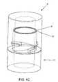
- FIG. 4is an exemplary embodiment of a subject cover assembly of a subject housing showing the internal structure in phantom.
- FIG. 4Ais a perspective view of the cover of FIG. 4 showing the sealing groove positioned on a sealing surface.
- FIG. 4Bis an exemplary embodiment of a cover assembly according to the subject invention having a sealing groove positioned on a sealing surface of the interior of the cover.
- FIG. 4Cshows an exemplary device according to the subject invention wherein the base and cover are mated together to form an intimate seal by way of at least corresponding threads and a sealing ridge and mated sealing groove, such as sealing ridge 15 ′ of FIG. 5 A and sealing groove 8 ′ of FIG. 4 B.
- FIG. 5is an exemplary embodiment of a subject base assembly of a subject housing.
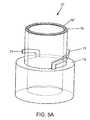
- FIG. 5Ashows an exemplary embodiment of a subject base having a sealing ridge poisoned on a sealing surface.
- FIG. 5Bshows an exemplary device according to the subject invention wherein the base and cover are mated together to form an intimate seal by way of at least corresponding threads and a sealing ridge and mated sealing groove such as sealing groove 16 of FIG. 5 and sealing groove 17 ′ of FIG. 4 .
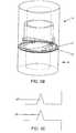
- FIG. 5Cshows a cross sectional view of an exemplary base having a sealing surface with a sealing ridge and an exemplary corresponding, mateable cover having a sealing surface with a sealing groove.
- FIG. 5Dshows an exemplary method of removing a single test strip from a subject base, such as base 6 of FIG. 5 .
- FIG. 6is another exemplary embodiment of a subject base assembly including a test strip engagement element having a lip extension and FIG. 6A is an exemplary embodiment showing removal of a test strip using a test strip engagement element having a lip extension.
- FIG. 6Bshows an exemplary embodiment of a subject test strip engagement element having a data storage element.
- FIGS. 7 and 7Ashow another exemplary embodiment of the subject invention having a slideably associated test strip engagement element and FIG. 7B shows the test strip engagement element of FIGS. 7 and 7A in association with a test strip stack.
- FIG. 7Cshows an exemplary method of removing a single test strip, such as a test strip from the test strip dispenser of FIGS. 7A and 7B .
- the subject devicesare characterized by having a housing made of a cover and a base configured to retain a plurality of test strips.
- the height of the baseis less than the height of each of the test strips, such that a portion of each of the test strips extends beyond the distal or top edge of the base.
- the subject devicesmay further be characterized as having a substantially air and moisture tight seal.
- a plurality of test strips stored in a subject deviceare provided. A single test strip is removed from the subject device by moving the test strip distal to the remaining test strips.
- kits for use in practicing the subject methodsare also provided by the subject invention.
- devicesare provided for dispensing test strips.
- devicesare provided for easily dispensing a single test strip from a plurality of test strips, i.e., dispensing each test strip separately or one test strip at a time.
- the inventionis suitable for dispensing any type of test strip for example electrochemical and colorimetric or photometric type test strips as are known in the art, where such test strips find use in the determination of a wide variety of different analyte concentrations, where representative analytes include, but are not limited to, glucose, cholesterol, lactate, alcohol, and the like.
- the subject test stripsare used to determine the glucose concentration in a physiological sample, e.g., interstitial fluid, blood, blood fractions, constituents thereof, and the like.
- a review of colorimetric and electrochemical test stripsis described first to provide a proper foundation for the subject invention, where such a review is by way of example and not limitation.
- test stripsincluding, but not limited to, colorimetric and electrochemical test strips, may be suitable for use with the present invention.
- the review of suitable test stripsis followed by a description of the subject test strip dispenser devices.
- the colorimetric or photometric (herein used interchangeably) reagent test strips employed in these embodiments of the subject inventionare generally made up of at least the following components: a matrix for receiving a sample, a reagent composition that typically includes one or more members of an analyte oxidation signal producing system and a support element.
- the colorimetric test stripsare typically configured and adapted to be received in an automated meter, as described below, for automatically determining the concentration of an analyte.
- An exemplary embodiment of a representative colorimetric test stripis shown in FIG. 2 A.
- the matrix 51 that is employed in the subject test stripsis an inert matrix which provides a support for the various members of the signal producing system, described infra, as well as the light absorbing or chromogenic product produced by the signal producing system, i.e., the indicator.
- the matrix 51is configured to provide a location for the physiological sample, e.g., blood, application and a location for the detection of the light-absorbing product produced by the indicator of the signal producing system.
- the matrix 51is one that is permissive of aqueous fluid flow through it and provides sufficient void space for the chemical reactions of the signal producing system to take place.
- matriceshave been developed for use in various analyte detection assays, which matrices may differ in terms of materials, dimensions and the like, where representative matrices include, but are not limited to, those described in U.S. Pat. Nos.
- the dimensions and porosity of the test strip 50may vary greatly, where the matrix 51 may or may not have pores and/or a porosity gradient, e.g. with larger pores near or at the sample application region and smaller pores at the detection region.
- Materials from which the matrix 51 may be fabricatedvary, and include polymers, e.g. polysulfone, polyamides, cellulose or absorbent paper, and the like, where the material may or may not be functionalized to provide for covalent or non-covalent attachment of the various members of the signal producing system.
- the subject test stripsfurther include one or more members of a signal producing system 52 which produces a detectable product in response to the presence of analyte, which detectable product can be used to derive the amount of analyte present in the assayed sample.
- the one or more members of the signal producing system 52are associated, e.g., covalently or non-covalently attached to, at least a portion of (i.e., the detection region) the matrix, and in many embodiments to substantially all of the matrix.
- the signal producing systemis an analyte oxidation signal producing system.
- analyte oxidation signal producing systemis meant that in generating the detectable signal from which the analyte concentration in the sample is derived, the analyte is oxidized by one or more suitable enzymes to produce an oxidized form of the analyte and a corresponding or proportional amount of hydrogen peroxide.
- the hydrogen peroxideis then employed, in turn, to generate the detectable product from one or more indicator compounds, where the amount of detectable product generated by the signal measuring system, i.e. the signal, is then related to the amount of analyte in the initial sample.
- the analyte oxidation signal producing systems present in the subject test stripsare also correctly characterized as hydrogen peroxide based signal producing systems.
- the hydrogen peroxide based signal producing systemsinclude an enzyme that oxidizes the analyte and produces a corresponding amount of hydrogen peroxide, whereby corresponding amount is meant that the amount of hydrogen peroxide that is produced is proportional to the amount of analyte present in the sample.
- This first enzymenecessarily depends on the nature of the analyte being assayed but is generally an oxidase.
- the first enzymemay be: glucose oxidase (where the analyte is glucose); cholesterol oxidase (where the analyte is cholesterol); alcohol oxidase (where the analyte is alcohol); lactate oxidase (where the analyte is lactate) and the like.
- Other oxidizing enzymes for use with these and other analytes of interestare known to those of skill in the art and may also be employed.
- the first enzymeis glucose oxidase.
- the glucose oxidasemay be obtained from any convenient source, e.g. a naturally occurring source such as Aspergillus niger or Penicillum, or recombinantly produced.
- a second enzyme of the signal producing systemmay be an enzyme that catalyzes the conversion of one or more indicator compounds into a detectable product in the presence of hydrogen peroxide, where the amount of detectable product that is produced by this reaction is proportional to the amount of hydrogen peroxide that is present.
- This second enzymeis generally a peroxidase, where suitable peroxidases include: horseradish peroxidase (HRP), soy peroxidase, recombinantly produced peroxidase and synthetic analogs having peroxidative activity and the like. See e.g., Y. Ci, F. Wang; Analytica Chimica Acta, 233 (1990), 299-302.
- the indicator compound or compounds, e.g., substratesare ones that are either formed or decomposed by the hydrogen peroxide in the presence of the peroxidase to produce an indicator dye that absorbs light in a predetermined wavelength range.
- the indicator dyeabsorbs strongly at a wavelength different from that at which the sample or the testing reagent absorbs strongly.
- the oxidized form of the indicatormay be a colored, faintly-colored, or colorless final product that evidences a change in color of the testing side of the membrane. That is to say, the testing reagent can indicate the presence of glucose in a sample by a colored area being bleached or, alternatively, by a colorless area developing color.
- Indicator compounds that are useful in the present inventioninclude both one- and two-component chromogenic substrates.
- One-component systemsinclude aromatic amines, aromatic alcohols, azines, and benzidines, such as tetramethyl benzidine-HCl.
- Suitable two-component systemsinclude those in which one component is MBTH, an MBTH derivative (see for example those disclosed in U.S. patent application Ser. No. 08/302,575, incorporated herein by reference), or 4-aminoantipyrine and the other component is an aromatic amine, aromatic alcohol, conjugated amine, conjugated alcohol or aromatic or aliphatic aldehyde.
- Exemplary two-component systemsare 3-methyl-2-benzothiazolinone hydrazone hydrochloride (MBTH) combined with 3-dimethylaminobenzoic acid (DMAB); MBTH combined with 3,5-dichloro-2-hydroxybenzene-sulfonic acid (DCHBS); and 3-methyl-2-benzothiazolinonehydrazone N-sulfonyl benzenesulfonate monosodium (MBTHSB) combined with 8-anilino-1 naphthalene sulfonic acid ammonium (ANS).
- the dye couple MBTHSB-ANSis preferred.
- signal producing systemsthat produce a fluorescent detectable product (or detectable non-fluorescent substance, e.g. in a fluorescent background) may be employed, such as those described in: Kiyoshi Zaitsu, Yosuke Ohkura: New fluorogenic substrates for Horseradish Peroxidase: rapid and sensitive assay for hydrogen peroxide and the Peroxidase. Analytical Biochemistry (1980) 109, 109-113.
- the matrix 51is usually attached to at least one support element, herein shown as attached to two support elements 54 and 56 .
- the support elements 54 and 56may be of a material that is sufficiently rigid to be inserted into the meter without undue bending or kinking.
- the support members 54 and 56are made of material such as polyolefins, e.g., polyethylene or polypropylene, polystyrene or polyesters, where the materials support members 54 and 56 may be the same or different. Consequently, the length of at least one of the support elements typically dictates or corresponds to the length of the test strip 50 .
- the length of the test strip 50generally ranges from about 3 mm to about 1000 mm, usually from about 10 mm to about 100 mm and more usually from about 20 mm to about 60 mm.
- the support elements 54 and 56usually are configured to enable the test strip 50 to be inserted into a meter.
- the support elements 54 and 56and thus the test strip 50 , are typically in the form of a substantially rectangular or square-like strip, where the dimensions of the support element vary according to a variety of factors, as will be apparent to those of skill in the art, and may be the same or different.
- the sampleis allowed to react with the members of the signal producing system to produce a detectable product that is present in an amount proportional to the initial amount present in the sample.
- the amount of detectable producti.e., signal produced by the signal producing system, is then determined and related to the amount of analyte in the initial sample.
- automated metersthat perform the above mentioned detection and relation steps are employed. The above described reaction, detection and relating steps, as well as instruments for performing the same, are further described in U.S. Pat. Nos.
- colorimetric reagent test stripssuitable for use with the subject invention include, but are not limited to, those described in U.S. Pat. Nos. 5,563,042; 5,753,452; 5,789,255, herein incorporated by reference.
- the electrochemical test strips used with the subject inventionare made up of two opposing metal electrodes separated by a thin spacer layer, where these components define a reaction area or zone.
- a redox reagent systemis located in the reaction area or zone.
- the electrochemical test stripsare usually configured and adapted to be received in an automated meter, as described below, for automatically determining the concentration of an analyte.
- An exemplary embodiment of a representative electrochemical test strip 60is shown in FIG. 2 B.
- the working and reference electrodes 62 and 64are generally configured in the form of elongated rectangular strips.
- the length of the electrodes 62 and 64ranges from about 1.9 cm to about 4.5 cm, usually from about 2.0 cm to about 2.8 cm.
- the width of the electrodes 62 and 64ranges from about 0.07 cm to about 0.76 cm, usually from about 0.24 cm to about 0.60 cm.
- the working and reference electrodes 62 and 64each have a thickness typically ranging from about 10 mm to about 100 nm and usually from about 10 mm to about 20 nm.
- the working and reference electrodes 62 and 64are further characterized in that at least the surfaces of the electrodes that face the reaction area 67 of the electrochemical cell in the strip is a metal, where metals of interest include palladium, gold, platinum, silver, iridium, carbon (conductive carbon ink), doped tin oxide, stainless steel and the like.
- the metalis gold or palladium.
- each of the electrodesis generally made up of an inert support material on the surface of which is present a thin layer of the metal component of the electrode.
- the thickness of the inert backing materialtypically ranges from about 25 to 500 ⁇ m, usually from about 50 to 400 ⁇ m, while the thickness of the metal layer typically ranges from about 10 to 100 nm and usually from about 10 to 40 nm, e.g., a sputtered metal layer.
- Any convenient inert backing materialmay be employed in the subject electrodes, where typically the material is a rigid material that is capable of providing structural support to the electrode and, in turn, the electrochemical test strip as a whole.
- Suitable materials that may be employed as the inert support materialinclude plastics, e.g., polyethylene terephthalate (PET), polyethylene terephthalate, glycol modified (PETG), polyimide, polycarbonate, polystyrene, silicon, ceramic, glass, and the like.
- plasticse.g., polyethylene terephthalate (PET), polyethylene terephthalate, glycol modified (PETG), polyimide, polycarbonate, polystyrene, silicon, ceramic, glass, and the like.
- the working and reference electrodes 62 and 64 as described abovegenerally face each other and are separated by only a short distance, such that the distance between the working and reference electrodes in the reaction zone or area 67 of the electrochemical test strip is extremely small.
- This minimal spacing of the working and reference electrodes 62 and 64 in the electrochemical test stripsis a result of the presence of a thin spacer layer 66 positioned or sandwiched between the working and reference electrodes.
- the thickness of this spacer layer 66may range from about 50 to 750 ⁇ m, and usually ranges from about 100 to 175 ⁇ m.
- the spacer layer 66is cut so as to provide a reaction zone or area 67 , where in many embodiments the volume of the reaction area or zone 67 typically ranges from about 0.1 to 10 ⁇ L, usually from about 0.2 to 5.0 ⁇ L.
- the spacer layermay have a circular reaction area cut with side inlet and outlet vents or ports, or other configurations, e.g., square, triangular, rectangular, irregularly shaped reaction areas, etc.
- the spacer layer 66may be fabricated from any convenient material, where representative suitable materials include polyethylene terephthalate (PET), polyethylene terephthalate, glycol modified (PETG), polyimide, polycarbonate, and the like, where the surfaces of the spacer layer 66 may be treated so as to be adhesive with respect to their respective electrodes and thereby maintain the structure of the electrochemical test strip 60 .
- PETpolyethylene terephthalate
- PETGglycol modified
- polyimidepolycarbonate
- the surfaces of the spacer layer 66may be treated so as to be adhesive with respect to their respective electrodes and thereby maintain the structure of the electrochemical test strip 60 .
- a reagent system or composition 69is present in the reaction area, where the reagent system 69 interacts with components in the fluid sample during the assay.
- Reagent systems of interesttypically include a redox couple.
- the redox couple of the reagent compositionwhen present, is made up of one or more redox couple agents.
- redox couple agentsinclude: ferricyanide, phenazine ethosulphate, phenazine methosulfate, pheylenediamine, 1-methoxy-phenazine methosulfate, 2,6-dimethyl-1,4-benzoquinone, 2,5-dichloro-1,4-benzoquinone, ferrocene derivatives, osmium bipyridyl complexes, ruthenium complexes, and the like.
- redox couples of particular interestare ferricyanide, and the like.
- reagentsthat may be present in the reaction area include buffering agents, e.g., citraconate, citrate, malic, maleic, phosphate, “Good” buffers and the like.
- agents that may be presentinclude: divalent cations such as calcium chloride, and magnesium chloride; surfactants such as Triton, Macol, Tetronic, Silwet, Zonyl, and Pluronic; stabilizing agents such as albumin, sucrose, trehalose, mannitol, and lactose.
- an electrochemical measurementis made using the reference and working electrodes.
- the electrochemical measurement that is mademay vary depending on the particular nature of the assay and the device with which the electrochemical test strip is employed, e.g., depending on whether the assay is coulometric, amperometric or potentiometric.
- the electrochemical measurementwill measure charge (coulometric), current (amperometric) or potential (potentiometric), usually over a given period of time following sample introduction into the reaction area.
- the amount of the analyte present in the sample introduced into the reaction zoneis then determined by relating the electrochemical signal to the amount of analyte in the sample.
- a representative reading device for automatically practicing these stepssuch that user need only apply sample to the reaction zone and then read the final analyte concentration result from the device, is further described in copending U.S. application Ser. No. 09/333,793 filed Jun. 15, 1999, the disclosure of which is herein incorporated by reference.
- the subject inventionincludes devices for dispensing a single test strip for use from a plurality of stored test strips, where the subject devices protect the retained test strips from adverse contaminants and conditions such as light, humidty, dust, dirt and oils or other contaminants from human hands, etc.
- the subject devicesare configured to retain from about 5 to about 100 test strips at one time, usually about 10 to about 80 test strips at one time and more usually from about 20 to about 60 test strips at one time, however the subject devices may be configured to retain more or fewer test strips.
- the subject devicesalso allow for easy re-loading of additional test strips, as will be apparent from the descriptions below.
- the subject devicesinclude a two piece housing, where such a housing is made up of two separate and separable assemblies: a cover assembly and a base assembly. In other words, the cover and base are not attached together.
- a separable configurationadvantageously enables substantially air and moisture tight seals to be created and maintained between the cover and base by a variety of means, as will be described in more detail below.
- the size and shape of the housingwill necessarily vary depending on a variety of factors, where such factors include, but are not limited to, the type and number of test strips retained therein, and the like. Accordingly, the shape of the housing may take any of a variety of shapes ranging from simple to complex.
- the housingmay be of a substantially rectangular, substantially square, substantially cylindrical, substantially round, substantially circular, substantially elliptical or substantially oval shape, etc., where in certain embodiments, circular, round or cylindrical or substantially circular, substantially round or substantially cylindrical shapes are of particular interest such that they enable a threaded engagement between the cover and base assemblies.
- the deviceis shaped to enable a threadable engagement between the cover and base assemblies.
- the shapemay be more complex such as a substantially irregular shape or the like.
- the size of the housingmay also vary depending on a variety of factors such as the type and number of test strips retained therein, and the like.
- the housingis configured such that the plurality of test strips is retained in the base portion of the housing.
- the test stripsmay be retained in the cover instead.
- the height of the base assemblyis less than the length of each of the test strips retained therein, i.e., a portion of each of the retained test strips extends beyond the distal edge or top portion of the base assembly, where usually the portion of the test strip that extends beyond the base assembly is the contact or non-testing area of the test strip so as to enable an individual to easily grasp a single test strip while avoiding many of the problems associated with prior art devices.
- the height of the base assemblyis typically at least about two thirds the length of each test strip (i.e., about one third of each test strip protrudes above the distal edge of the base assembly), where the height of the base assembly may be as little as about one half or one quarter or less the length of each test strip.
- the total height of the housingi.e., the base and cover assemblies together
- the width or diameter of the housingwill typically range from about 10 mm to about 40 mm, usually from about 10 mm to about 30 mm and more usually from about 15 mm to about 20 mm.
- the height of the base assemblywill typically range from about 5 mm to about 700 mm, usually from about 10 mm to about 40 mm and more usually from about 15 mm to about 30 mm and the height of the cover assembly will typically range from about 4 mm to about 600 mm, usually from about 8 mm to about 35 mm and more usually from about 15 mm to about 25 mm.
- the housingmay be manufactured from a variety of materials, where the bottom and cover of the housing may be manufactured from the same or different materials, but where such materials will not substantially interfere with the testing reagents of the test strips retained therein.
- materialsmay include, but are not limited to, plastics such as polytetrafluoroethylene, polypropylene, polyethylene, polystyrene, polycarbonate and blends thereof, metals such as stainless steel, aluminum and alloys thereof, siliceous material, e.g., glass materials, and the like.
- the cover and base assembliesare alignable in a closed configuration such that the housing is substantially air and moisture tight when in a closed configuration, i.e., the cover will form a substantially air and moisture tight seal with the base when the two are contacted together in a closed position.
- substantially air and moisture tight sealis meant that the housing is capable of preventing substantial air and moisture from entering the housing when the housing is in a closed position.
- the inside of the housingis a substantially air tight and moisture free environment and more specifically the test strips inside the housing are in a substantially air tight and moisture free environment when the housing is in a closed configuration.
- the housingincludes at least one attachment means, where such attachment means aligns and mates, i.e., attaches, the base and cover assemblies together to form an intimate seal, i.e. a seal that is substantially air and moisture tight.
- Representative attachment meansinclude, but are not limited to, at least one of: one or more threaded engagements, i.e., one or more thread locking means, a snap fit mechanism, a frictional engagement, a cover seating mechanism, an O-ring gasket, a lock and key mechanism and a tensioning clamp, where each of these will now be describe in more detail.
- a threaded engagementi.e., one or more thread locking means may be employed to form an intimate contact between the base and cover assemblies.
- the cover assemblymay include one or more threads such as a 1 ⁇ 4, 1 ⁇ 2, 3 ⁇ 4 or more thread(s) on the inside of the cover assembly, where such a thread(s) corresponds and operatively associates with a similar thread(s) positioned on the base assembly.
- the thread(s) of the base and coverare configured to align and clamp the two assemblies together to form an intimate seal between the cover and the base, i.e., a substantially air and moisture proof seal.
- a substantially air and moisture proof seali.e., a substantially air and moisture proof seal.
- a frictional engagementi.e., a seating mechanism
- a frictional engagementmay be employed to form an intimate contact between the base and cover assemblies.
- pressure between the surfaces of the base and cover assembliesis maximized by mating two surfaces together with force.
- the cover assemblymay include one or more protrusions or sealing surfaces inside the cover which mates or seats adjacent a sealing surface or edge or ledge of the base assembly and/or the assemblies may be dimensioned such that a frictional force is applied upon insertion of the cover assembly over the base assembly, or vice versa.
- the base and coverare forced together to create an intimate seal, i.e., a substantially air and moisture proof seal.
- an O-ring gasketmay be employed to form an intimate contact between the base and cover assemblies.
- an O-ringmay be positioned on the cover or the base to form an intimate contact when the cover and base are in a closed position.
- a lock and key mechanismmay be employed.
- the covermay include a protrusion on its inside which mates with a corresponding groove on the base, or vice versa, to secure the assemblies in an intimately contacted configuration.
- a tensioning clampsimilar to that which is used to fasten and close ski boots (see for example U.S. Pat. No. 6,145,168, the disclosure of which is herein incorporated by reference) may be employed.
- a gripping arm or the likemay be coupled to the outside of the cap.
- a gripping arminteracts with one of a plurality of teeth which protrude from the outside of the base.
- the twoare further associated by moving an actuating arm associated with the gripping arm to apply a force or tension to the clamp, thus moving the cap and base closer together to form a secure seal.
- a snap fit mechanismmay be employed.
- snap fit mechanismis meant any suitable “built in” or integral latching mechanism for attaching one part to another.
- a snap fitis different from loose or chemical attachment methods in that it requires no additional pieces, materials or tools to carry out the attaching function.
- Representative snap fit mechanisms suitable for use with the present inventionare described in Bonenberger, P., The First Snap-Fit Handbook, Hanzer (2000), incorporated herein in its entirety, and include, but are not limited to, planar snap fit, cantilever snap fit, trap snap fit, torsion snap fit and annular snap fit.
- one or more, sometimes two or three or more of the above described attachment meansmay be used to create an intimate seal between the cover and the base, where such a closure enables a substantially air and moisture tight seal.
- the subject devicemay further include moisture absorbent reagents or components such as desiccant material, silica gel and the like, where such material is capable of absorbing moisture from the environment surrounding the stored test strips.
- moisture absorbent reagents or componentssuch as desiccant material, silica gel and the like, where such material is capable of absorbing moisture from the environment surrounding the stored test strips.
- Such absorbent reagents or componentsmay be retained in one or more compartments positioned inside the cover and/or base assemblies.
- the covermay include a sealing ridge configured such that a corresponding groove of the base (or the cover if the ridge is positioned on the base) is configured to receive and mate with the ridge of the cover when the cover and the base are in a closed position.
- the ridgeis typically tapered to enable the edges of the base (or the cover if the ridge is positioned on the base) to fit snuggly between the ridge and the walls of the cover.
- a sealing ridgeis positioned on a first assembly such as a cover and the second assembly such as a base, in this particular example, includes a corresponding groove configured to accept the ridge of the first assembly such that the ridge is snuggly fit in the groove of the second assembly to provide a substantially air and moisture tight seal.
- the base of the present inventionmay also include an urging means, where such an urging means is capable of applying a force to the test strips stored in the device to assist in dispensing and preventing the test strips from inadvertently falling out of the housing.
- the urging meansmay be integral with the housing, i.e., a unitary piece of construction, or may be a separate piece of material or separate component.
- a variety of urging meansmay be used to accomplish such an applied force to the test strips, where representative means or mechanisms include, but are not limited to, a spring such as a coil or leaf spring, etc., a sponge, foam, and a pusher or plunger rod.
- the urging meansmay exert a force from one or more than one direction of the test strips, for example the urging means may exert a force from all directions or opposing forces from two directions, etc.
- a forcemay be exerted from a first direction such that the urging means exerts a force to a test strip on one end of the test strip stack and a second force may be exerted from a second direction such that the urging means exerts a force, e.g., an opposing force, to a test strip on the opposite end of the test strip stack from the first test strip, where the first and second forces may be applied by the same or different mechanisms.
- a substantially planar, rigid platemay be employed to hold the test strips together in a suitable orientation or arrangement.
- one or more such substantially planar, rigid platesmay be configured to contact one or both ends of the test strip stack to assist in dispensing the test strips and preventing the test strips from inadvertently falling out of the housing.
- the platemay include one or more protrusions to limit or minimize the degree of contact between the plate and an adjacent test strip such that only the protrusion(s) contact an adjacent test strip, as opposed to the all or substantially all of the planar face of the plate contacting the test strip.
- the base assemblymay converge to an apex, i.e., extends inward of the base, or may include a pattern or one or more protrusions thereon, to enable further segregation of the test strips retained therein.
- the basemay include test strip segregation means, where such means enable the test strips to be stepped, staggered or otherwise segregated to facilitate the removal of a single test strip from the stack.
- a test strip engagement elementis included, where such a test strip engagement element is configured to enable removal of a single test strip from a plurality of test strips stored in the housing, i.e., from a stack of stored test strips.
- the test strip engagement elementmay be integral with the housing, i.e., may be a unitary piece of construction or may be a separate piece of material or component, where such a component may be fixed in place or may be readily removable.
- test strip engagement elementfacilitates removal of a single test strip from a plurality of test strips stored in the housing. Additionally, the test strip engagement element is also configured to prevent removal of any and all other test strips, i.e., it only enables one test strip to be removed at a time.
- the test strip engagement elementincludes a lip extension at its distal end, where the lip extension is configured to allow a single test strip to slide or move along its surface, i.e., advance adjacent its surface, while catching any and all other test strips under the lip extension.
- the test strip engagement elementis multi sided such that each side is symmetrical, i.e., substantially the same as any other side, where such a configuration enables a greater number of test strips to be dispensed.
- the exact number of sideswill vary depending on the particular configuration of the engagement element, the test strips to be dispensed, etc.
- the engagement elementmay have two sides, i.e., two test strip dispensing sides, or more.
- lipsextend over two sides of a central area such that there is a first lip extending over a first side and a second lip extending over a second side.
- a first plurality or stack of test stripsmay be positioned adjacent a first side of the engagement element and a second plurality or stack may be positioned adjacent a second side of the engagement element.
- the test strip engagement elementincludes at least one test strip grasping means, where such a test strip grasping means is configured to grasp or hold a single test strip and advance or move the grasped test strip in a direction away from the test strip stack, either automatically or manually.
- a test strip engagement element having at least one test strip grasping meansmay move a test strip automatically or manually by a finger or the like. Regardless of whether the test strip engagement element having at least one test strip grasping means is actuated automatically or manually, a variety of grasping means may be employed to grasp a test strip.
- test strip engagement elementis slideably associated with a portion of the housing such as the base assembly.
- the test strip engagement elementincludes a handle at its distal end to facilitate sliding the engagement element by an individual.
- the handleis attached to a connection means such as a rod or plate or the like, which is further associated with at least one grasping means such as at least one ledge, tooth or arm laterally extending from the proximal end of the engagement element.
- at least one ledge, tooth or armextends from the proximal end substantially perpendicular to the connection means, e.g., a rod or plate mid portion.
- the grasping meansis thus configured to engage an end or edge of a test strip and to move it, i.e., slideably move it or carry it forward, in a direction away from the remaining test strips, i.e., a direction distal to the stack of test strips or substantially out of the housing, so that the single test strip is easy to grasp for removal from the housing.
- the engagement elementmay include a magnet means for magnetically engaging a test strip also having a magnet means and moving the test strip.
- a surface or area of the engagement elementmay include a coating layer such as an adhesive or the like to facilitate engagement of a test strip and/or may include a pattern such as a pattern of ridges and/or protrusions to facilitate engagement of a test strip.
- the test strip engagement elementmay be configured to include a data storage element capable of storing data pertaining to the test strips stored in the housing, such as calibration data, expiration date, the number strips used/available, and the like, where the data may be easily transferred or communicated to an external device such as a meter for automatically determining the presence or concentration of at least one analyte in the physiological sample, where such meters are known in the art.
- the data storage elementmay be in any convenient form, depending on a variety of factors such as the amount of data to be stored and the like, where representative data storage elements include, but a are not limited to, a bar code, electronic storage element, and the like.
- the test strip engagement elementalso includes electrical contacts or other suitable means for operatively coupling or transferring data to such an external device such as a meter or the like.
- the base assemblymay further include a test strip movement means for automatically advancing or moving a top most test strip in a direction away from the remaining test strips.
- the subject test strip dispensersmay include a means for automatically advancing a test strip.
- a test strip movement meansis provided, where such a movement means may be actuated by a button or the like present on the exterior of the device.
- the movement meansmay include any suitable means capable of engaging and moving a test strip automatically.
- FIG. 3shows an external view of an exemplary embodiment of a housing assembly 2 , as described above.
- the housing assembly 2includes a base assembly 6 and a cover assembly 4 , herein shown in a closed position.
- the housingis substantially air and moisture tight.
- the housingis shown having a cylindrical shape; however, as mentioned above, the housing may be of any convenient shape.
- FIG. 4shows an exemplary embodiment of a subject cover assembly of a subject housing showing the internal structure, such as cover assembly 4 of FIG. 3 .
- Cover assembly 4includes three attachment means, each of which is capable of forming an intimate contact between the base and cover assemblies.
- the seating mechanism 8includes a protrusion or ledge 8 , i.e., a sealing surface 8 , positioned inside the cover assembly which frictionally mates or seats adjacent a distal edge, lip or ledge, i.e., a sealing surface, of a base assembly such as sealing surface or edge 15 of base assembly 6 of FIG. 5 , herein shown as a protrusion or ledge 8 which encircles the inside perimeter of the cover; however, it will be apparent that the protrusion need not encircle the entire perimeter.
- the sealing surface 8may include a sealing ridge or groove, as will be described below.
- sealing surface 17 of cover 4i.e., edge, ledge or lip 17
- a sealing surfacei.e., edge, lip or ledge of a corresponding base assembly component, such as sealing surface or edge 13 of FIG. 5 , for example.
- one or more sealing surfaceswill include a sealing ridge for mating with a corresponding sealing groove on a corresponding assembly, as will be further described below.
- a base assemblymay include a sealing ridge positioned on a sealing surface (see for example ridge 16 of FIG. 5 and ridge 15 ′ of FIG. 5A ) and a corresponding cover may include a sealing groove, such as sealing groove 17 ′ of FIGS.
- FIG. 5Bwhich shows a base assembly having a sealing ridge positioned on a sealing surface 13 and a corresponding cover assembly having a sealing groove positioned on a sealing surface 17 , wherein the two are mated to form an intimate seal
- FIG. 4Cwhich shows a cover having a sealing groove positioned on a sealing surface 8 mated with a base having a sealing ridge positioned on a sealing surface 15 to form an intimate seal
- FIG. 4Ashows a perspective view of cover 4 . Accordingly, the cover 4 has been rotated about 45° about an axis transverse to the longitudinal axis of the cover 4 .
- FIG. 4Ashows sealing surface 17 having sealing groove 17 ′ described above positioned thereon for receiving a sealing ridge positioned on a base assembly such as sealing ridge 16 of FIG. 5 .
- the cover assemblye.g., the sealing surface 17 may instead include a sealing ridge and a corresponding base assembly could instead include the mateable sealing groove.
- FIG. 4Bshows a sealing groove 8 ′ positioned on sealing surface 8 of cover 9 , which may be in addition to or in place of a groove or ridge positioned on sealing surface 17 of the cover assembly.
- sealing surface 8may instead include a sealing ridge.
- Sealing groove 8 ′is configured to mate with a corresponding sealing ridge on a base assembly, such as sealing ridge 15 ′ positioned on a sealing surface 15 of base 11 of FIG. 5 A.
- FIG. 4Cshows a cover having a sealing groove 8 ′ positioned on a sealing surface 8 mated with a base having a corresponding sealing ridge 15 ′ positioned on a sealing surface 15 to form an intimate seal.
- Cover assembly 4also includes two thread locking means 10 , such as two 1 ⁇ 4 turn threads (as mentioned, a 3 ⁇ 4 turn thread, 1 ⁇ 2 turn thread, 1 turn thread or thread having more than 1 turn may also be used, as will be obvious to one of skill in the art), as described above.
- the threadsadvantageously allow a small hand torque to create a large or substantial sealing pressure or force on the sealing surfaces.
- FIG. 5shows a view of an exemplary base assembly, such as base assembly 6 of FIG. 3 .
- Base assembly 6is shown having a plurality of test strips 14 stored therein, where the test strips are urged together by urging means 12 .
- Base assembly 6also includes an attachment means, herein shown as thread locking means 11 , e.g., 1 ⁇ 4 turn threads (or threads having less or more turns) positioned on the exterior of the base, which corresponds to the thread locking means 10 positioned on the interior of the cover assembly 4 , as described above.
- Base assembly 6may be made of two or more sections, as seen here as two integral sections 18 and 20 , where section 18 has a smaller diameter than section 20 so as to accommodate a cover assembly and create a flush housing exterior.
- sealing surface 13having a tapered or substantially “V” shaped sealing ridge 16 , which is configured to be received or mated with a corresponding sealing groove positioned on a sealing surface of a cover, such as sealing groove 17 ′ of sealing surface or edge 17 of cover 4 of FIG. 4 , such that the ridge 16 is fit snuggly in the groove of a corresponding cover.
- the basemay include a sealing groove such that a sealing ridge of a cover may be fit or received by a groove of a base to provide a substantially air and moisture tight seal.
- the seal surface or edge of either the base or covermay further include a gasket (not shown).
- FIG. 5Ashows an exemplary base assembly 11 , which is substantially similar to base assembly 6 of FIG. 5 , except that it has a sealing ridge 15 ′ positioned on a sealing surface other than sealing surface 13 , i.e., sealing ridge 15 ′ is positioned on sealing surface 15 , which may be in addition to or in place of a sealing ridge positioned on another sealing surface such as ridge 16 positioned on sealing surface 13 of FIG. 5 .
- the sealing ridgesmay instead be sealing grooves and vice versa.
- sealing ridge 16 and sealing ridge 15 ′are configured and dimensioned to correspond with a respective corresponding groove positioned on a cover assembly such that the groove on the cover assembly tightly receives the ridge 16 or 15 ′ therein when mated together to form a snug fit.
- FIG. 5Cshows a cross sectional view of the sealing surfaces of an exemplary base and cover having a sealing ridge and a corresponding groove. Accordingly, FIG. 5C shows a sealing ridge such as sealing ridge 16 of FIG. 5 (or sealing ridge 15 ′ of FIG. 5A ) and a corresponding cover having a mateable groove such as groove 17 ′ of FIG. 4 (or groove 8 ′ of FIG. 4 B).
- the ridgemay be positioned on the cover and the mateable groove positioned on the base.
- the ridgeis typically configured to have a substantially “V”-like shape, but other suitable shapes are, of course, possible.
- FIG. 6shows yet another embodiment of an exemplary subject base assembly.
- Base assembly 6 ′is substantially similar to base assembly 6 of FIG. 5 .
- base assembly 6 ′includes a test strip engagement element 22 which is configured to facilitate removal of a single test strip from a plurality of test strips stored in the housing.
- the test strip engagement element 22is also configured to prevent removal of any other test strip, i.e., it only enables single test strip removal.
- the test strip engagement element 22includes a first lip extension 23 on a first side and a second lip extension 27 on a second side, both positioned at the distal end 25 of the test strip engagement element, where the lip extensions 23 and 27 are configured to allow a single test strip to slide or move along the surface of the engagement element, e.g., the lip extension, while catching any other test strip under the lip extension, as shown in FIG. 6 A and as will be explained in greater detail below.
- the engagement element 22has two test strip engaging sides with respective lip extension 23 and 27 ; however fewer or greater than the illustrated number of sides and lip extensions may be present.
- test strip stack 14is positioned inside a test strip compartment 18 , where such a compartment may be integral with the base or may be a separate piece and may also be readily removable for easy test strip re-filling.
- a similar test strip stack 14 and test strip compartmentmay be positioned on the opposing side of the engagement element so as to be similarly associated with lip extension 27 .
- recess 19which is configured to function as a lock-key attachment means when operatively associated with a corresponding protrusion on a test strip engagement element, such as protrusion 1 on test strip engagement element 28 of FIG. 6 B.
- FIG. 6Bshows a full view of an exemplary test strip engagement element, similar to the test strip engagement element 22 of FIG. 6 .
- the proximal end 26 of test strip engagement element 28includes a data storage element 29 and an electronic coupling means 21 for operatively coupling to an external or remote device and thus communicating or transferring data thereto.
- FIGS. 7 and 7Ashow another exemplary embodiment of the subject invention having a slideably associated test strip engagement element.
- FIG. 7shows an exterior view of a base member 30 having a slideably associated test strip engagement element 32 associate therewith.
- a portion of test strip engagement element 32is disposed within the base assembly, while handle 34 is positioned outside the base so as to be accessible to a user of the device.
- Test strip engagement element 32is also associated with a stack of test strips such that it picks and advances or moves a single test strip, herein shown as test strip 14 ′, distal to the base for removal (see FIG. 7 C).
- the slideably associated test strip engagement elementmay be moved automatically or manually, for example by an individual engaging and moving the handle thereof.
- FIG. 7Billustrates an exploded view of the association of test strip engagement element 32 with a test strip stack.
- the distal end of the test strip engagement element 32includes a handle 34 attached to a connecting means or rod or plate mid section 33 .
- the proximal end 35 of the test strip engagement element 32includes at least one test strip grasping means, herein shown as two ledges or arms 36 , where such grasping means are configured to grasp or engage edge E of an end or top most test strip 14 ′ from a plurality or stack of test strips 14 and slideably move test strip 14 ′ away or distally from the stack 14 so it can be easily grasped by an individual.
- test strip stack 14may further be associated with an urging means 12 , herein shown as a spring element 12 , and a substantially planar, rigid plate 39 for maintaining the test strips together in a suitable orientation.
- FIG. 7Ashows an internal view (shown in phantom) of the base assembly 30 of FIG. 7 .
- the phantom linesillustrate the recess 100 which retains the test strip stack 14 in the base.
- the baseis configured to include a negative space dimensioned and configured to retain the plurality of test strips in the device.
- the recess 100is also configured, i.e., a negative space is provided, to accommodate engagement element 32 and grasping means 36 , e.g., recesses 36 ′ are configured to accommodate grasping means 36 .
- Also provided by the subject inventionare methods for dispensing a test strip from a plurality or stack of test strips. More specifically, methods are provided that enable a single test strip to be grasped easily, for example by a visually and/or dextrally impaired individual such as a visually and/or dextrally impaired diabetic and the like.
- the first stepis to provide a test strip dispenser, where such a dispenser is configured to store at least one and more likely a plurality of test strips, such as the test strip dispenser devices described above.
- a test stripis easily dispensed for use by exerting a first force upon the plurality of test strips, where such a first force urges the plurality of test strips together to facilitate the dispensing task.
- a test stripis removed from the plurality of test strips by applying a second opposing force and slideably moving or advancing a test strip away from the plurality, e.g., in a direction distal to the plurality of test strips, where such a second force and subsequent movement may be accomplished manually or automatically, for example with a suitable test strip movement means, and will typically be accomplished manually, for example by a finger.
- a test strip dispenserwhere the height of the base assembly or the portion that retains or stores the test strips is less than the height of each of the retained test strips, as described above, to provide easy access to a top most test strip while minimizing direct contact with other test strips. More specifically, the height of the base assembly is less than the length of each of the test strips retained therein, i.e., a portion of each of the retained test strips extends beyond the distal edge or top portion of the base assembly, where usually the portion of the test strip that extends beyond the base assembly is the contact or non-testing area of the test strip.
- the height of the base assemblyis typically at least about two thirds the length of each test strip (i.e., one third of each test strip protrudes above the distal edge of the base assembly), where the height of the base assembly may be as little as about one half or one quarter or less the length of each test strip, where exemplary dimensions for a cylindrically shaped device having a base assembly that has a height that is less than the length of each of the retained test strips are described above and will not be repeated here.
- FIG. 5Dshows an exemplary method of removal of a single test strip from a subject base such as base 6 of FIG. 5 .
- a first forceis applied by, for example, an urging means 12 , to a first end of the plurality of test strips 14 .
- a test strip movement meanse.g., finger or other test strip movement means (manual or automatic), applies a second force to the opposite end of the test strip stack, i.e., to the top most test strip 14 ′ to be removed from the plurality, and moves the test strip 14 ′ in a direction, e.g., distal direction, away from the plurality.
- the portion of the test strip contacted by a finger or the likewill be a portion suitable for handling, i.e., a contact area such as a non-testing or non-reaction area.
- the plurality of test stripsis further held together by a rigid plate or the like, as described above, where such a plate also minimizes the chances that the test strips will inadvertently fall out of the dispenser.
- this particular embodimentprovides an easy method of accessing a single test strip without the need of a device having complex, multiple, moveable parts.
- the test stripsneed not be stacked in a precise manner, but rather each strip need only be positioned behind another in some fashion. As such, ease of manufacturing and use are increased.
- a test stripis removed from a plurality or stack of test strips by moving, either automatically or manually with a finger, the test strip along or adjacent a lip extension, where such a lip extension serves to remove a single test strip from a plurality of test strips while also preventing removal of any other test strip, i.e., it only enables single test strip removal by providing a simple method of segregating a single test strip from the plurality of test strips.
- a test stripis advanced or moved by a test strip movement means (i.e., an automatic movement means or manual movement means such as a finger) adjacent a lip extension while other, remaining test strips are caught or retained under the lip extension and thus prevented from being removed.
- a test strip movement meansi.e., an automatic movement means or manual movement means such as a finger
- a test strip engagement element having a lip extensionsuch as described above, is provided.
- a finger or other meanse.g., automatic means, engages a test strip, i.e., engages a top most test strip 14 ′ from the plurality of test strips stored in the dispenser, for removal.
- the portion of the test strip contacted by a finger or the likewill be a portion suitable for handling, i.e., a contact areas such as a non-testing or non-reaction area.
- test strip 14Once a test strip is engaged with a finger or other movement means, the engaged test strip is advanced or moved in a direction, i.e., a distal direction as shown by the arrow, away from the plurality of test strips, where it is advanced adjacent the lip extension and further segregated from the plurality so that it can be easily grasped and removed for use.
- any and all other test stripssuch as test strip 14 ′′ which may have also been somewhat advanced, are prevented from further advancement by engagement with an area under the lip extension.
- test stripsneed not be stacked in a precise manner in this embodiment, but rather each strip need only be positioned behind another in some fashion. As such, ease of manufacturing and use are increased.
- a test stripi.e., an end or top most test strip is engaged by a grasping means and advanced or moved in a direction, i.e., a distal direction, away from the plurality of test strips so that it may be easily grasped.
- a test strip engagement element having a grasping meansengages a test strip, either manually or automatically, and advances the test strip away from the remaining test strips (see FIG. 7C which shows such an exemplary method of removing a single test strip, such as a method of removing a single test strip from the test strip dispenser of FIGS. 7 A and 7 B).
- a test strip engagement element having a grasping meansengages a test strip, either manually or automatically, and advances the test strip away from the remaining test strips (see FIG. 7C which shows such an exemplary method of removing a single test strip, such as a method of removing a single test strip from the test strip dispenser of FIGS. 7 A and 7 B).
- the grasping meansmay grasp and move a test strip manually, e.g., move a test strip by a finger or the like, or automatically by a suitable movement means.
- the test stripmay also be grasped or engaged by a magnet means, an adhesive, a coating layer or pattern associated with the test strip engagement element.
- the magnet means, adhesive, coating layer or patternmay be associated with the test strip, as well as or in addition to, the test strip engagement element.
- test strips of the plurality of test stripsmay further be urged together, for example on a side opposite the engagement element, to better enable grasping by the grasping means (see for example FIG. 7 B).
- the processmay then be repeated for the next sequential test strip or current, top most test strip.
- substantially air and moisture tight sealis meant that the housing is capable of preventing substantial air and/or moisture from entering the housing when the housing is in a closed position.
- the inside of the housingis a substantially air tight and moisture free environment and more specifically the test strips inside the housing are in a substantially air tight and moisture free environment when the housing is in a closed configuration.
- One or more of the below described methods for accomplishing a substantially air and moisture free housing sealmay be employed.
- the substantially air and moisture tight sealis accomplished by threadably engaging the cover and base assemblies of the test strip dispenser device.
- a cover assemblyis provided with a thread positioned on the cover, such as on the inside of a substantially circular or cylindrical cover and a base assembly is provided with a corresponding thread, for example positioned on the outside of the base.
- the cover and base assembliesare aligned or mated together to form a closed dispenser, typically the cover will encompass a portion of the base such that a portion of the base, i.e., the area of the base having a thread, is inside the cover so as to create a flush housing exterior.
- the corresponding threadsare threaded together, e.g., by a 1 ⁇ 4 turn, 1 ⁇ 2 turn, 3 ⁇ 4 turn or even a full turn or two or more turns, or the like, to associate the threads of the cover and base together to create a substantially air and moisture tight seal.
- threadably engaging the assembliesadvantageously allows a small hand torque to create a large or substantial sealing pressure or force on the sealing surfaces to create a tight seal therebetween.
- a substantially air and moisture tight sealis accomplished by intimately seating the base assembly into the cover assembly, i.e., frictionally engaging the cover and base assemblies together.
- a seating mechanismas described above, may be employed to form an intimate contact between the base and cover assemblies.
- one or more protrusions positioned on the inside the coveris mated adjacent a distal edge or ledge of the base assembly, where such a mating forms an intimate seal, i.e., a substantially air and moisture proof seal.
- an O-ring gasketmay be employed to form an intimate contact between the base and cover assemblies.
- an O-ringmay be positioned on the cover or the base to form an intimate contact when the cover and base are in a closed position.
- a lock and key mechanismmay be employed.
- a protrusion on the inside coveris aligned and mated with a corresponding groove on the base, or vice versa, securing the assemblies in an intimately contacted configuration.
- one of the assembliesis urged away from the other to “unlock” the protrusion from the groove.
- a tab or lipmay be provided on the cover assembly adjacent a protrusion, e.g., on the outside of the cover assembly. Engaging the tab disengages the protrusion or rather moves the protrusion out of its corresponding groove on the base assembly.
- other means for “unlocking” the mechanismmay, of course, also be employed.
- a method employing a tensioning clamp similar to that which is used to fasten and close ski bootsmay be used to create a substantially air and moisture tight seal. Accordingly, a cover and base are brought into a closing position and a gripping arm on, for example the outside of the cover, is caused to interact with one of a plurality of teeth, for example positioned on the outside of the base. A tension is created, i.e., a force is applied, by moving an actuating arm operatively associated with the gripping arm, bringing the cover and base closer together to form a close, intimate contact which is substantially air and moisture impenetrable.
- the substantially air and moisture tight sealis effected and maintained by mating or tightly fitting or positioning a sealing ridge of a first assembly as described above (i.e., a first assembly such as a base assembly) with a corresponding groove on the second assembly (i.e., a cover in this particular example).
- a sealing ridge of a first assemblyas described above (i.e., a first assembly such as a base assembly)
- a corresponding groove on the second assemblyi.e., a cover in this particular example.
- the receiving groove positioned on a sealing surface of an assembly such as a cover assemblyreceives a corresponding sealing ridge positioned on a mateable assembly such as a base assembly, where such groove/ridge interaction provides a substantially air and moisture tight seal between the base and cover assemblies when they are in a closed configuration.
- kits for practicing the subject methodsare provided.
- the subject kitsat least include one or more test strip dispensing devices of the subject invention. Oftentimes, a plurality of subject devices is included.
- the subject kitsmay also include one or more test strips, usually a plurality of test strips.
- the kitsmay further include a meter for automatically determining the presence and/or concentration of at least one analyte in a physiological sample applied to a test strip.
- the kitsmay further include instructions for using the subject devices for dispensing test strips and may also include instruction for determining the presence and/or concentration of at least one analyte in a physiological sample applied to a test strip.
- the instructionsmay be printed on a substrate, such as paper or plastic, etc.
- the instructionsmay be present in the kits as a package insert, in the labeling of the container of the kit or components thereof (i.e., associated with the packaging or sub-packaging) etc.
- the instructionsare present as an electronic storage data file present on a suitable computer readable storage medium, e.g., CD-ROM, diskette, etc.
- the above described inventionprovides a simple, quick and convenient way to dispense test strips.
- the above described inventionprovides a number of advantages, including, but not limited to, ease and low cost manufacture, portability, ease of use, particularly for visually and dextrally impaired individuals, and minimal test strip damage from light, humidity, and other environmental contaminants including oils and the like from a user's hands.
- the subject inventionrepresents a significant contribution to the art.
Landscapes
- Health & Medical Sciences (AREA)
- Engineering & Computer Science (AREA)
- Life Sciences & Earth Sciences (AREA)
- Biomedical Technology (AREA)
- Physics & Mathematics (AREA)
- Chemical & Material Sciences (AREA)
- Pathology (AREA)
- Analytical Chemistry (AREA)
- Immunology (AREA)
- Biochemistry (AREA)
- General Health & Medical Sciences (AREA)
- General Physics & Mathematics (AREA)
- Food Science & Technology (AREA)
- Medicinal Chemistry (AREA)
- Hematology (AREA)
- Optics & Photonics (AREA)
- Urology & Nephrology (AREA)
- Molecular Biology (AREA)
- Biophysics (AREA)
- Investigating Or Analysing Biological Materials (AREA)
- Investigating Or Analyzing Non-Biological Materials By The Use Of Chemical Means (AREA)
- Sampling And Sample Adjustment (AREA)
- Automatic Analysis And Handling Materials Therefor (AREA)
Abstract
Description
Claims (14)
Priority Applications (15)
| Application Number | Priority Date | Filing Date | Title |
|---|---|---|---|
| US10/052,212US6872358B2 (en) | 2002-01-16 | 2002-01-16 | Test strip dispenser |
| IL15363102AIL153631A0 (en) | 2002-01-16 | 2002-12-24 | Test strip dispenser |
| MXPA03000334AMXPA03000334A (en) | 2002-01-16 | 2003-01-10 | Test strip dispenser. |
| TW092100741ATW200404040A (en) | 2002-01-16 | 2003-01-15 | Test strip dispenser |
| RU2003101105/14ARU2003101105A (en) | 2002-01-16 | 2003-01-15 | DEVICE FOR ISSUING TEST STRIPES |
| JP2003007512AJP2004003958A (en) | 2002-01-16 | 2003-01-15 | Apparatus, method, and kit for portioning test strip |
| KR10-2003-0002658AKR20030062277A (en) | 2002-01-16 | 2003-01-15 | Test strip dispenser |
| DE60311019TDE60311019D1 (en) | 2002-01-16 | 2003-01-15 | Dispensing device for test strips |
| EP03250256AEP1329395B1 (en) | 2002-01-16 | 2003-01-15 | Test strip dispenser |
| NO20030193ANO20030193L (en) | 2002-01-16 | 2003-01-15 | Test Strip Dispenser |
| CA002416780ACA2416780A1 (en) | 2002-01-16 | 2003-01-16 | Test strip dispenser |
| PL03358316APL358316A1 (en) | 2002-01-16 | 2003-01-16 | Apparatus for storing and dispensing piece-by-piece test strips |
| CN03102750ACN1432813A (en) | 2002-01-16 | 2003-01-16 | Test chip and strip distributor |
| HK03106909.4AHK1054725B (en) | 2002-01-16 | 2003-09-25 | Test strip dispenser |
| US11/048,250US20050169810A1 (en) | 2002-01-16 | 2005-01-31 | Test strip dispenser |
Applications Claiming Priority (1)
| Application Number | Priority Date | Filing Date | Title |
|---|---|---|---|
| US10/052,212US6872358B2 (en) | 2002-01-16 | 2002-01-16 | Test strip dispenser |
Related Child Applications (1)
| Application Number | Title | Priority Date | Filing Date |
|---|---|---|---|
| US11/048,250DivisionUS20050169810A1 (en) | 2002-01-16 | 2005-01-31 | Test strip dispenser |
Publications (2)
| Publication Number | Publication Date |
|---|---|
| US20030133847A1 US20030133847A1 (en) | 2003-07-17 |
| US6872358B2true US6872358B2 (en) | 2005-03-29 |
Family
ID=21976132
Family Applications (2)
| Application Number | Title | Priority Date | Filing Date |
|---|---|---|---|
| US10/052,212Expired - LifetimeUS6872358B2 (en) | 2002-01-16 | 2002-01-16 | Test strip dispenser |
| US11/048,250AbandonedUS20050169810A1 (en) | 2002-01-16 | 2005-01-31 | Test strip dispenser |
Family Applications After (1)
| Application Number | Title | Priority Date | Filing Date |
|---|---|---|---|
| US11/048,250AbandonedUS20050169810A1 (en) | 2002-01-16 | 2005-01-31 | Test strip dispenser |
Country Status (13)
| Country | Link |
|---|---|
| US (2) | US6872358B2 (en) |
| EP (1) | EP1329395B1 (en) |
| JP (1) | JP2004003958A (en) |
| KR (1) | KR20030062277A (en) |
| CN (1) | CN1432813A (en) |
| CA (1) | CA2416780A1 (en) |
| DE (1) | DE60311019D1 (en) |
| IL (1) | IL153631A0 (en) |
| MX (1) | MXPA03000334A (en) |
| NO (1) | NO20030193L (en) |
| PL (1) | PL358316A1 (en) |
| RU (1) | RU2003101105A (en) |
| TW (1) | TW200404040A (en) |
Cited By (91)
| Publication number | Priority date | Publication date | Assignee | Title |
|---|---|---|---|---|
| US20020104849A1 (en)* | 2000-12-29 | 2002-08-08 | Jean-Pierre Giruad | Meter strip dispenser assembly |
| US20040048359A1 (en)* | 2002-07-12 | 2004-03-11 | Schmeling William R. | Test strips moveable by magnetic fields |
| US20050025674A1 (en)* | 2003-07-31 | 2005-02-03 | William Romanauskas | Centrifuge sample jar and closure |
| US20050106069A1 (en)* | 2002-02-28 | 2005-05-19 | Arkray, Inc. | Measurement instrument, measurement tool storage case and operation mechanism |
| US20060079809A1 (en)* | 2004-09-29 | 2006-04-13 | Daniel Goldberger | Blood monitoring system |
| US20060229531A1 (en)* | 2005-02-01 | 2006-10-12 | Daniel Goldberger | Blood monitoring system |
| US20070065338A1 (en)* | 2005-09-06 | 2007-03-22 | Jerry Schindler | Testing strip and dispenser |
| US20070080093A1 (en)* | 2005-10-11 | 2007-04-12 | Agamatrix, Inc. | Vial for test strips |
| US20070084749A1 (en)* | 2005-10-18 | 2007-04-19 | Agamatrix, Inc. | Vial for test strips |
| US20070191716A1 (en)* | 2004-09-29 | 2007-08-16 | Daniel Goldberger | Blood monitoring system |
| US20070196242A1 (en)* | 2006-02-23 | 2007-08-23 | Agamatrix, Inc. | Used test strip storage container |
| US20070264166A1 (en)* | 2006-05-09 | 2007-11-15 | Becton, Dickinson And Company | Method and apparatus for dispensing diagnostic test strips |
| US20070264165A1 (en)* | 2006-05-09 | 2007-11-15 | Becton, Dickinson And Company | Method and apparatus for dispensing diagnostic test strips |
| US20080045395A1 (en)* | 2004-12-23 | 2008-02-21 | Romanauskas William A | Centrifuge adapter and closure |
| US20080094804A1 (en)* | 2005-01-14 | 2008-04-24 | Reynolds Jeffrey S | Test Sensor Cartridges and Sensor-Dispensing Instruments |
| US20080200838A1 (en)* | 2005-11-28 | 2008-08-21 | Daniel Goldberger | Wearable, programmable automated blood testing system |
| US20080275324A1 (en)* | 2006-05-23 | 2008-11-06 | Daniel Goldberger | Fluid Access Interface |
| US20090200326A1 (en)* | 2002-10-10 | 2009-08-13 | Jean Pierre Giraud | Resealable moisture tight container assembly for strips and the like having a lip snap seal |
| US20090230144A1 (en)* | 2005-03-22 | 2009-09-17 | Bayer Healthcare Llc | Cartridge with a wheel for sealing the opening |
| US20100127014A1 (en)* | 2008-11-26 | 2010-05-27 | Chan Frank A | Drum type container for analytical elements |
| US20100140116A1 (en)* | 2007-01-29 | 2010-06-10 | Matthias Stiene | Resealable container for storing moisture sensitive test elements |
| US7875047B2 (en) | 2002-04-19 | 2011-01-25 | Pelikan Technologies, Inc. | Method and apparatus for a multi-use body fluid sampling device with sterility barrier release |
| US7892183B2 (en) | 2002-04-19 | 2011-02-22 | Pelikan Technologies, Inc. | Method and apparatus for body fluid sampling and analyte sensing |
| US7901365B2 (en) | 2002-04-19 | 2011-03-08 | Pelikan Technologies, Inc. | Method and apparatus for penetrating tissue |
| US7909778B2 (en) | 2002-04-19 | 2011-03-22 | Pelikan Technologies, Inc. | Method and apparatus for penetrating tissue |
| US7909774B2 (en) | 2002-04-19 | 2011-03-22 | Pelikan Technologies, Inc. | Method and apparatus for penetrating tissue |
| US7909777B2 (en) | 2002-04-19 | 2011-03-22 | Pelikan Technologies, Inc | Method and apparatus for penetrating tissue |
| US7909775B2 (en) | 2001-06-12 | 2011-03-22 | Pelikan Technologies, Inc. | Method and apparatus for lancet launching device integrated onto a blood-sampling cartridge |
| US7914465B2 (en) | 2002-04-19 | 2011-03-29 | Pelikan Technologies, Inc. | Method and apparatus for penetrating tissue |
| US20110077480A1 (en)* | 2009-03-27 | 2011-03-31 | Intellidx, Inc. | Fluid transfer system and method |
| US20110073610A1 (en)* | 2009-03-05 | 2011-03-31 | Jean-Pierre Giraud | Two-shell and two-drawer containers |
| US20110127175A1 (en)* | 2009-11-30 | 2011-06-02 | Roche Diagnostics Operations, Inc. | Test strip container with expandable insert and methods of manufacturing and utilization thereof |
| US7976476B2 (en) | 2002-04-19 | 2011-07-12 | Pelikan Technologies, Inc. | Device and method for variable speed lancet |
| US7981056B2 (en) | 2002-04-19 | 2011-07-19 | Pelikan Technologies, Inc. | Methods and apparatus for lancet actuation |
| US7981055B2 (en) | 2001-06-12 | 2011-07-19 | Pelikan Technologies, Inc. | Tissue penetration device |
| US7988645B2 (en) | 2001-06-12 | 2011-08-02 | Pelikan Technologies, Inc. | Self optimizing lancing device with adaptation means to temporal variations in cutaneous properties |
| US20110204079A1 (en)* | 2010-02-22 | 2011-08-25 | Chan Frank A | Container for dispensing a single test strip |
| US8007446B2 (en) | 2002-04-19 | 2011-08-30 | Pelikan Technologies, Inc. | Method and apparatus for penetrating tissue |
| US20110210021A1 (en)* | 2007-09-03 | 2011-09-01 | Airsec S.A.S. | Vial |
| US8062231B2 (en) | 2002-04-19 | 2011-11-22 | Pelikan Technologies, Inc. | Method and apparatus for penetrating tissue |
| US8079960B2 (en) | 2002-04-19 | 2011-12-20 | Pelikan Technologies, Inc. | Methods and apparatus for lancet actuation |
| US20120016213A1 (en)* | 2010-07-15 | 2012-01-19 | Becton, Dickinson And Company | Blood test strip and an intravenous catheter system |
| US8197421B2 (en) | 2002-04-19 | 2012-06-12 | Pelikan Technologies, Inc. | Method and apparatus for penetrating tissue |
| US8221334B2 (en) | 2002-04-19 | 2012-07-17 | Sanofi-Aventis Deutschland Gmbh | Method and apparatus for penetrating tissue |
| WO2012109047A1 (en) | 2011-02-07 | 2012-08-16 | Sawa Kevin G | Device for singulating and dispensing rigid and semi-rigid strips |
| US8251921B2 (en) | 2003-06-06 | 2012-08-28 | Sanofi-Aventis Deutschland Gmbh | Method and apparatus for body fluid sampling and analyte sensing |
| US8262614B2 (en) | 2003-05-30 | 2012-09-11 | Pelikan Technologies, Inc. | Method and apparatus for fluid injection |
| US8267870B2 (en) | 2002-04-19 | 2012-09-18 | Sanofi-Aventis Deutschland Gmbh | Method and apparatus for body fluid sampling with hybrid actuation |
| US8282576B2 (en) | 2003-09-29 | 2012-10-09 | Sanofi-Aventis Deutschland Gmbh | Method and apparatus for an improved sample capture device |
| US8292826B1 (en) | 2011-06-21 | 2012-10-23 | YofiMETER, Inc. | Cocking and advancing mechanism for analyte testing device |
| US8296918B2 (en) | 2003-12-31 | 2012-10-30 | Sanofi-Aventis Deutschland Gmbh | Method of manufacturing a fluid sampling device with improved analyte detecting member configuration |
| US20120305419A1 (en)* | 2011-05-31 | 2012-12-06 | Tara Chand Singhal | Integrated blood glucose measuring device with a test strip packaging system |
| US8333717B1 (en) | 2011-06-21 | 2012-12-18 | Yofimeter, Llc | Test unit cartridge for analyte testing device |
| US8333710B2 (en) | 2002-04-19 | 2012-12-18 | Sanofi-Aventis Deutschland Gmbh | Tissue penetration device |
| US20130020347A1 (en)* | 2011-06-10 | 2013-01-24 | Union Street Brand Packaging | Strip Dispenser |
| US8360992B2 (en) | 2002-04-19 | 2013-01-29 | Sanofi-Aventis Deutschland Gmbh | Method and apparatus for penetrating tissue |
| US8372016B2 (en) | 2002-04-19 | 2013-02-12 | Sanofi-Aventis Deutschland Gmbh | Method and apparatus for body fluid sampling and analyte sensing |
| US8382682B2 (en) | 2002-04-19 | 2013-02-26 | Sanofi-Aventis Deutschland Gmbh | Method and apparatus for penetrating tissue |
| US8394343B2 (en) | 2010-04-27 | 2013-03-12 | Roche Diagnostics Operations, Inc. | Integrated test strip container with retaining insert |
| US8435190B2 (en) | 2002-04-19 | 2013-05-07 | Sanofi-Aventis Deutschland Gmbh | Method and apparatus for penetrating tissue |
| US8439872B2 (en) | 1998-03-30 | 2013-05-14 | Sanofi-Aventis Deutschland Gmbh | Apparatus and method for penetration with shaft having a sensor for sensing penetration depth |
| US8535618B1 (en) | 2010-09-08 | 2013-09-17 | Robert L. Werner | Test strip dispenser |
| US8540116B2 (en) | 2006-09-06 | 2013-09-24 | Csp Technologies, Inc. | Non-round moisture-tight re-sealable containers with round sealing surfaces |
| US8556829B2 (en) | 2002-04-19 | 2013-10-15 | Sanofi-Aventis Deutschland Gmbh | Method and apparatus for penetrating tissue |
| US8574895B2 (en) | 2002-12-30 | 2013-11-05 | Sanofi-Aventis Deutschland Gmbh | Method and apparatus using optical techniques to measure analyte levels |
| US8641644B2 (en) | 2000-11-21 | 2014-02-04 | Sanofi-Aventis Deutschland Gmbh | Blood testing apparatus having a rotatable cartridge with multiple lancing elements and testing means |
| US8652831B2 (en) | 2004-12-30 | 2014-02-18 | Sanofi-Aventis Deutschland Gmbh | Method and apparatus for analyte measurement test time |
| US8668656B2 (en) | 2003-12-31 | 2014-03-11 | Sanofi-Aventis Deutschland Gmbh | Method and apparatus for improving fluidic flow and sample capture |
| US8702624B2 (en) | 2006-09-29 | 2014-04-22 | Sanofi-Aventis Deutschland Gmbh | Analyte measurement device with a single shot actuator |
| US8721671B2 (en) | 2001-06-12 | 2014-05-13 | Sanofi-Aventis Deutschland Gmbh | Electric lancet actuator |
| US8784335B2 (en) | 2002-04-19 | 2014-07-22 | Sanofi-Aventis Deutschland Gmbh | Body fluid sampling device with a capacitive sensor |
| US8828203B2 (en) | 2004-05-20 | 2014-09-09 | Sanofi-Aventis Deutschland Gmbh | Printable hydrogels for biosensors |
| US8965476B2 (en) | 2010-04-16 | 2015-02-24 | Sanofi-Aventis Deutschland Gmbh | Tissue penetration device |
| US8961432B2 (en) | 2011-06-21 | 2015-02-24 | Yofimeter, Llc | Analyte testing devices |
| US9144401B2 (en) | 2003-06-11 | 2015-09-29 | Sanofi-Aventis Deutschland Gmbh | Low pain penetrating member |
| US9226699B2 (en) | 2002-04-19 | 2016-01-05 | Sanofi-Aventis Deutschland Gmbh | Body fluid sampling module with a continuous compression tissue interface surface |
| US20160018336A1 (en)* | 2014-07-18 | 2016-01-21 | Ronald Schornstein | Methods and kits for analyzing automotive fluids |
| US9248267B2 (en) | 2002-04-19 | 2016-02-02 | Sanofi-Aventis Deustchland Gmbh | Tissue penetration device |
| US9314194B2 (en) | 2002-04-19 | 2016-04-19 | Sanofi-Aventis Deutschland Gmbh | Tissue penetration device |
| US9351680B2 (en) | 2003-10-14 | 2016-05-31 | Sanofi-Aventis Deutschland Gmbh | Method and apparatus for a variable user interface |
| US9375169B2 (en) | 2009-01-30 | 2016-06-28 | Sanofi-Aventis Deutschland Gmbh | Cam drive for managing disposable penetrating member actions with a single motor and motor and control system |
| US9386944B2 (en) | 2008-04-11 | 2016-07-12 | Sanofi-Aventis Deutschland Gmbh | Method and apparatus for analyte detecting device |
| US9427532B2 (en) | 2001-06-12 | 2016-08-30 | Sanofi-Aventis Deutschland Gmbh | Tissue penetration device |
| US9623412B2 (en) | 2006-03-13 | 2017-04-18 | Trividia Health, Inc. | Method and apparatus for coding diagnostic meters |
| US9775553B2 (en) | 2004-06-03 | 2017-10-03 | Sanofi-Aventis Deutschland Gmbh | Method and apparatus for a fluid sampling device |
| US9795747B2 (en) | 2010-06-02 | 2017-10-24 | Sanofi-Aventis Deutschland Gmbh | Methods and apparatus for lancet actuation |
| US9820684B2 (en) | 2004-06-03 | 2017-11-21 | Sanofi-Aventis Deutschland Gmbh | Method and apparatus for a fluid sampling device |
| US9914126B2 (en) | 2011-11-28 | 2018-03-13 | Roche Diabetes Care, Inc. | Storage container for biosensor test elements |
| US20210147122A1 (en)* | 2008-05-15 | 2021-05-20 | Csp Technologies, Inc. | Vial with non-round seal |
| US11517896B2 (en) | 2020-08-14 | 2022-12-06 | Luna Pharmaceuticals, Inc. | Test strip holder |
| US11559810B2 (en) | 2006-03-13 | 2023-01-24 | Trividia Health, Inc. | Method and apparatus for coding diagnostic meters |
Families Citing this family (49)
| Publication number | Priority date | Publication date | Assignee | Title |
|---|---|---|---|---|
| US20030195435A1 (en)* | 2002-04-12 | 2003-10-16 | Williams Arthur G. | Method and apparatus for collecting and transporting capillary blood samples for diagnostic and research evaluation |
| US8394328B2 (en)* | 2003-12-31 | 2013-03-12 | Nipro Diagnostics, Inc. | Test strip container with integrated meter having strip coding capability |
| US8394337B2 (en)* | 2003-12-31 | 2013-03-12 | Nipro Diagnostics, Inc. | Test strip container with integrated meter |
| US8147426B2 (en)* | 2003-12-31 | 2012-04-03 | Nipro Diagnostics, Inc. | Integrated diagnostic test system |
| US9012232B2 (en)* | 2005-07-15 | 2015-04-21 | Nipro Diagnostics, Inc. | Diagnostic strip coding system and related methods of use |
| MXPA06009431A (en)* | 2004-02-18 | 2007-03-21 | Universal Biosensors Pty Ltd | Strip ejection system. |
| USD506832S1 (en) | 2004-06-02 | 2005-06-28 | Home Diagnostics, Inc. | Meter for an integrated diagnostic test system |
| USD507657S1 (en) | 2004-06-02 | 2005-07-19 | Home Diagnostics, Inc. | Meter for an integrated diagnostic test system |
| US7582262B2 (en)* | 2004-06-18 | 2009-09-01 | Roche Diagnostics Operations, Inc. | Dispenser for flattened articles |
| US7458942B2 (en)* | 2004-09-22 | 2008-12-02 | Medtox | Systems and methods for collecting, testing and transporting liquid biological specimens |
| US7337918B2 (en)* | 2004-12-03 | 2008-03-04 | Nova Biomedical Corporation | Test strip dispenser |
| US10258278B2 (en) | 2004-12-20 | 2019-04-16 | Ipventure, Inc. | Method and apparatus to sense hydration level of a person |
| US8734341B2 (en)* | 2004-12-20 | 2014-05-27 | Ipventure, Inc. | Method and apparatus to sense hydration level of a person |
| US11013461B2 (en) | 2004-12-20 | 2021-05-25 | Ipventure, Inc. | Method and apparatus for hydration level of a person |
| USD561904S1 (en) | 2005-01-31 | 2008-02-12 | Home Diagnostics, Inc. | Meter for an integrated diagnostic test system |
| US20060275890A1 (en)* | 2005-06-06 | 2006-12-07 | Home Diagnostics, Inc. | Method of manufacturing a disposable diagnostic meter |
| US7955856B2 (en) | 2005-07-15 | 2011-06-07 | Nipro Diagnostics, Inc. | Method of making a diagnostic test strip having a coding system |
| US8999125B2 (en) | 2005-07-15 | 2015-04-07 | Nipro Diagnostics, Inc. | Embedded strip lot autocalibration |
| US12303292B2 (en) | 2005-11-02 | 2025-05-20 | Ipventure, Inc. | Method and apparatus for health condition related to the skin of a person |
| GB2433926A (en)* | 2005-12-22 | 2007-07-11 | Lifescan Scotland Inc | Container with RFID for storing calibration information |
| US20070143968A1 (en)* | 2005-12-28 | 2007-06-28 | Shu-Chuan Tseng | Comfortable handle |
| US8388906B2 (en)* | 2006-03-13 | 2013-03-05 | Nipro Diagnostics, Inc. | Apparatus for dispensing test strips |
| US8388905B2 (en)* | 2006-03-13 | 2013-03-05 | Nipro Diagnostics, Inc. | Method and apparatus for coding diagnostic meters |
| US20080020452A1 (en)* | 2006-07-18 | 2008-01-24 | Natasha Popovich | Diagnostic strip coding system with conductive layers |
| JP4871083B2 (en)* | 2006-09-27 | 2012-02-08 | テルモ株式会社 | Body fluid collection unit |
| US7935307B2 (en)* | 2007-05-31 | 2011-05-03 | EOS Health, DVC. | Disposable, refillable glucometer with cell phone interface for transmission of results |
| US20100000905A1 (en)* | 2008-07-03 | 2010-01-07 | Abbott Diabetes Care, Inc. | Strip vial and cap |
| US7896703B2 (en)* | 2008-07-17 | 2011-03-01 | Abbott Diabetes Care Inc. | Strip connectors for measurement devices |
| US7946866B2 (en)* | 2008-08-28 | 2011-05-24 | Abbott Diabetes Care Inc. | Apparatus for preventing electrical shock in devices |
| JP2012504233A (en)* | 2008-09-30 | 2012-02-16 | メナイ メディカル テクノロジーズ リミテッド | Sample measurement system |
| WO2010121080A1 (en)* | 2009-04-15 | 2010-10-21 | Abbott Diabetes Care Inc. | Method and device for detecting usb cable connection |
| EP2480884B1 (en) | 2009-09-24 | 2018-08-08 | Roche Diabetes Care GmbH | Test strip stack and method for its production |
| GB201005359D0 (en) | 2010-03-30 | 2010-05-12 | Menai Medical Technologies Ltd | Sampling plate |
| GB201005357D0 (en) | 2010-03-30 | 2010-05-12 | Menai Medical Technologies Ltd | Sampling plate |
| WO2012058237A1 (en) | 2010-10-26 | 2012-05-03 | Abbott Diabetes Care Inc. | Analyte measurement devices and systems, and components and methods related thereto |
| US9713440B2 (en) | 2010-12-08 | 2017-07-25 | Abbott Diabetes Care Inc. | Modular analyte measurement systems, modular components thereof and related methods |
| USD680454S1 (en) | 2011-10-25 | 2013-04-23 | Abbott Diabetes Care Inc. | Analyte meter and strip port |
| KR101340006B1 (en)* | 2011-12-01 | 2013-12-10 | 주식회사 세라젬메디시스 | Cartridge of analysis apparatus |
| US10983065B2 (en)* | 2012-08-08 | 2021-04-20 | Healthy.Io Ltd. | Method, apparatus and system for detecting and determining compromised reagent pads by quantifying color changes induced by exposure to a hostile environment |
| US12146878B2 (en) | 2012-08-08 | 2024-11-19 | Healthy.Io Ltd. | Method, apparatus and system for detecting and determining comprised reagent pads by quantifying color changes induced by exposure to a hostile environment |
| EP3004866B1 (en)* | 2013-05-24 | 2019-11-06 | Premier Biotech, Inc. | Multi-stage oral-fluid testing device |
| US9737254B2 (en)* | 2015-11-23 | 2017-08-22 | Novtex Llc | Personal medical testing housing |
| CN105615897B (en)* | 2016-04-05 | 2018-12-18 | 京东方科技集团股份有限公司 | A kind of blood sugar monitor and its monitoring method |
| JP6738719B2 (en)* | 2016-12-06 | 2020-08-12 | テラメックス株式会社 | Test piece storage container |
| TW201906579A (en)* | 2017-07-07 | 2019-02-16 | 訊映光電股份有限公司 | Blood glucose meter structure combined with test can |
| CN107512472B (en)* | 2017-09-14 | 2023-02-10 | 国网吉林省电力有限公司电力科学研究院 | Dust-free filter storage box for dust sampling and usage method thereof |
| CN111746906B (en)* | 2020-06-29 | 2021-10-08 | 石冰 | Sample strorage device for prospecting |
| AU2022358642B2 (en) | 2022-01-11 | 2023-10-05 | Beauty Molecules International Limited | Cosmetic case |
| CN118961180B (en)* | 2024-10-15 | 2025-01-24 | 珠海市聚兆科技有限公司 | A silicone button performance testing device |
Citations (28)
| Publication number | Priority date | Publication date | Assignee | Title |
|---|---|---|---|---|
| US2641358A (en) | 1950-03-14 | 1953-06-09 | Worcester Moulded Plastics Com | Razor blade dispenser |
| US3393831A (en) | 1966-11-25 | 1968-07-23 | Scient Plastic Corp | Glass slide dispenser |
| US4114780A (en) | 1976-12-02 | 1978-09-19 | Shaul Sharon | Combination industrial razor blade dispenser and used blade receiver |
| US4187077A (en) | 1978-06-05 | 1980-02-05 | Eastman Kodak Company | Container with article positioning element for dispensing reagent coated slides to an automated analyzer |
| EP0045077A2 (en) | 1980-07-30 | 1982-02-03 | Eduard Hansjörg Schweizer | Holders containing a stack of objects |
| USRE30895E (en) | 1976-09-03 | 1982-04-06 | Filter paper dispenser | |
| US4464552A (en)* | 1981-10-29 | 1984-08-07 | James River-Dixie/Northern, Inc. | Packaging |
| US4717018A (en) | 1984-06-28 | 1988-01-05 | Boehringer Mannheim Gmbh | Container for longitudinally extending diagnostic test strips |
| US4817820A (en) | 1987-08-27 | 1989-04-04 | Miles Inc. | Slide dispenser for a reagent cannister |
| US4911344A (en) | 1988-03-23 | 1990-03-27 | Tek-Aids Inc. | Strip dispenser box |
| US5100621A (en)* | 1988-09-20 | 1992-03-31 | Hygeia Sciences, Inc. | Test kit for diagnostic procedures |
| WO1994010558A1 (en)* | 1992-11-03 | 1994-05-11 | Enviromed Plc | Electrochemical sensor |
| US5328082A (en) | 1991-09-09 | 1994-07-12 | Ecolab Inc. | Apparatus for dispensing moisture-sensitive unit dose packages |
| US5409133A (en) | 1994-02-17 | 1995-04-25 | Allway Tools, Inc. | Razor blade dispenser |
| US5426032A (en) | 1986-08-13 | 1995-06-20 | Lifescan, Inc. | No-wipe whole blood glucose test strip |
| FR2714895A1 (en) | 1994-01-10 | 1995-07-13 | Benloulou Joseph | Bus or metro ticket dispenser |
| US5489414A (en) | 1993-04-23 | 1996-02-06 | Boehringer Mannheim, Gmbh | System for analyzing compounds contained in liquid samples |
| US5505308A (en)* | 1993-08-27 | 1996-04-09 | Boehringer Mannheim Gmbh | System for the storage of test elements |
| US5510266A (en) | 1995-05-05 | 1996-04-23 | Bayer Corporation | Method and apparatus of handling multiple sensors in a glucose monitoring instrument system |
| US5534224A (en) | 1993-07-16 | 1996-07-09 | Fuji Photo Film Co., Ltd. | Chemical analysis film cartridge |
| US5542567A (en) | 1994-08-31 | 1996-08-06 | Nice-Pak Products, Inc. | Moist tissue package construction and tissue |
| US5575403A (en) | 1995-01-13 | 1996-11-19 | Bayer Corporation | Dispensing instrument for fluid monitoring sensors |
| US5630986A (en) | 1995-01-13 | 1997-05-20 | Bayer Corporation | Dispensing instrument for fluid monitoring sensors |
| US5736103A (en)* | 1996-08-09 | 1998-04-07 | Lifescan, Inc. | Remote-dosing analyte concentration meter |
| WO1998047007A1 (en) | 1997-04-11 | 1998-10-22 | Roche Diagnostics Gmbh | Test element storage device |
| US5894927A (en) | 1997-06-09 | 1999-04-20 | Chesebrough-Pond's Usa Co., Division Of Conopco, Inc. | Dispenser for applicator pads |
| US5971941A (en) | 1997-12-04 | 1999-10-26 | Hewlett-Packard Company | Integrated system and method for sampling blood and analysis |
| US6036924A (en) | 1997-12-04 | 2000-03-14 | Hewlett-Packard Company | Cassette of lancet cartridges for sampling blood |
Family Cites Families (28)
| Publication number | Priority date | Publication date | Assignee | Title |
|---|---|---|---|---|
| JPS5912135B2 (en) | 1977-09-28 | 1984-03-21 | 松下電器産業株式会社 | enzyme electrode |
| EP0078636B2 (en) | 1981-10-23 | 1997-04-02 | MediSense, Inc. | Sensor for components of a liquid mixture |
| US4734360A (en) | 1983-07-12 | 1988-03-29 | Lifescan, Inc. | Colorimetric ethanol analysis method and test device |
| US4900666A (en) | 1983-07-12 | 1990-02-13 | Lifescan, Inc. | Colorimetric ethanol analysis method and test device |
| US5059394A (en) | 1986-08-13 | 1991-10-22 | Lifescan, Inc. | Analytical device for the automated determination of analytes in fluids |
| AU640162B2 (en) | 1989-08-28 | 1993-08-19 | Lifescan, Inc. | Blood separation and analyte detection techniques |
| US5620863A (en) | 1989-08-28 | 1997-04-15 | Lifescan, Inc. | Blood glucose strip having reduced side reactions |
| US5306623A (en) | 1989-08-28 | 1994-04-26 | Lifescan, Inc. | Visual blood glucose concentration test strip |
| JPH0820412B2 (en) | 1990-07-20 | 1996-03-04 | 松下電器産業株式会社 | Quantitative analysis method and device using disposable sensor |
| GR1002549B (en) | 1992-05-12 | 1997-01-28 | Lifescan Inc. | Fluid conducting test strip with Transport Medium |
| US5843691A (en) | 1993-05-15 | 1998-12-01 | Lifescan, Inc. | Visually-readable reagent test strip |
| US5563031A (en) | 1994-09-08 | 1996-10-08 | Lifescan, Inc. | Highly stable oxidative coupling dye for spectrophotometric determination of analytes |
| US5526120A (en) | 1994-09-08 | 1996-06-11 | Lifescan, Inc. | Test strip with an asymmetrical end insuring correct insertion for measuring |
| US5515170A (en) | 1994-09-08 | 1996-05-07 | Lifescan, Inc. | Analyte detection device having a serpentine passageway for indicator strips |
| MX9701792A (en) | 1994-09-08 | 1997-06-28 | Johnson & Johnson | Optically readable strip for analyte detection having on-strip standard. |
| US5573452A (en) | 1995-07-18 | 1996-11-12 | Liu; Yu-Chieh | Drill grinder |
| AU722471B2 (en) | 1995-10-17 | 2000-08-03 | Lifescan, Inc. | Blood glucose strip having reduced sensitivity to hematocrit |
| AUPN661995A0 (en) | 1995-11-16 | 1995-12-07 | Memtec America Corporation | Electrochemical cell 2 |
| IL120587A (en) | 1996-04-04 | 2000-10-31 | Lifescan Inc | Reagent test strip for determination of blood glucose |
| US5753429A (en) | 1996-08-09 | 1998-05-19 | Lifescan, Inc. | Analyte concentration measurement using a hollow frustum |
| US5846486A (en) | 1996-08-09 | 1998-12-08 | Lifescan, Inc. | Hollow frustum reagent test device |
| AUPP250398A0 (en) | 1998-03-20 | 1998-04-23 | Usf Filtration And Separations Group Inc. | Sensor with improved shelf life |
| IT1298824B1 (en) | 1998-03-27 | 2000-02-02 | Htm Sport Spa | LEVER STRUCTURE, ESPECIALLY FOR SPORTS FOOTWEAR |
| US6475372B1 (en) | 2000-02-02 | 2002-11-05 | Lifescan, Inc. | Electrochemical methods and devices for use in the determination of hematocrit corrected analyte concentrations |
| US6193873B1 (en) | 1999-06-15 | 2001-02-27 | Lifescan, Inc. | Sample detection to initiate timing of an electrochemical assay |
| US6716577B1 (en) | 2000-02-02 | 2004-04-06 | Lifescan, Inc. | Electrochemical test strip for use in analyte determination |
| US6620310B1 (en) | 2000-12-13 | 2003-09-16 | Lifescan, Inc. | Electrochemical coagulation assay and device |
| US6558528B1 (en) | 2000-12-20 | 2003-05-06 | Lifescan, Inc. | Electrochemical test strip cards that include an integral dessicant |
- 2002
- 2002-01-16USUS10/052,212patent/US6872358B2/ennot_activeExpired - Lifetime
- 2002-12-24ILIL15363102Apatent/IL153631A0/enunknown
- 2003
- 2003-01-10MXMXPA03000334Apatent/MXPA03000334A/enactiveIP Right Grant
- 2003-01-15JPJP2003007512Apatent/JP2004003958A/enactivePending
- 2003-01-15KRKR10-2003-0002658Apatent/KR20030062277A/ennot_activeWithdrawn
- 2003-01-15NONO20030193Apatent/NO20030193L/ennot_activeApplication Discontinuation
- 2003-01-15TWTW092100741Apatent/TW200404040A/enunknown
- 2003-01-15RURU2003101105/14Apatent/RU2003101105A/ennot_activeApplication Discontinuation
- 2003-01-15EPEP03250256Apatent/EP1329395B1/ennot_activeExpired - Lifetime
- 2003-01-15DEDE60311019Tpatent/DE60311019D1/ennot_activeExpired - Fee Related
- 2003-01-16CACA002416780Apatent/CA2416780A1/ennot_activeAbandoned
- 2003-01-16CNCN03102750Apatent/CN1432813A/enactivePending
- 2003-01-16PLPL03358316Apatent/PL358316A1/ennot_activeApplication Discontinuation
- 2005
- 2005-01-31USUS11/048,250patent/US20050169810A1/ennot_activeAbandoned
Patent Citations (29)
| Publication number | Priority date | Publication date | Assignee | Title |
|---|---|---|---|---|
| US2641358A (en) | 1950-03-14 | 1953-06-09 | Worcester Moulded Plastics Com | Razor blade dispenser |
| US3393831A (en) | 1966-11-25 | 1968-07-23 | Scient Plastic Corp | Glass slide dispenser |
| USRE30895E (en) | 1976-09-03 | 1982-04-06 | Filter paper dispenser | |
| US4114780A (en) | 1976-12-02 | 1978-09-19 | Shaul Sharon | Combination industrial razor blade dispenser and used blade receiver |
| US4187077A (en) | 1978-06-05 | 1980-02-05 | Eastman Kodak Company | Container with article positioning element for dispensing reagent coated slides to an automated analyzer |
| EP0045077A2 (en) | 1980-07-30 | 1982-02-03 | Eduard Hansjörg Schweizer | Holders containing a stack of objects |
| US4464552A (en)* | 1981-10-29 | 1984-08-07 | James River-Dixie/Northern, Inc. | Packaging |
| US4717018A (en) | 1984-06-28 | 1988-01-05 | Boehringer Mannheim Gmbh | Container for longitudinally extending diagnostic test strips |
| US5426032A (en) | 1986-08-13 | 1995-06-20 | Lifescan, Inc. | No-wipe whole blood glucose test strip |
| US4817820A (en) | 1987-08-27 | 1989-04-04 | Miles Inc. | Slide dispenser for a reagent cannister |
| US4911344A (en) | 1988-03-23 | 1990-03-27 | Tek-Aids Inc. | Strip dispenser box |
| US5100621A (en)* | 1988-09-20 | 1992-03-31 | Hygeia Sciences, Inc. | Test kit for diagnostic procedures |
| US5328082A (en) | 1991-09-09 | 1994-07-12 | Ecolab Inc. | Apparatus for dispensing moisture-sensitive unit dose packages |
| WO1994010558A1 (en)* | 1992-11-03 | 1994-05-11 | Enviromed Plc | Electrochemical sensor |
| US5489414A (en) | 1993-04-23 | 1996-02-06 | Boehringer Mannheim, Gmbh | System for analyzing compounds contained in liquid samples |
| US5534224A (en) | 1993-07-16 | 1996-07-09 | Fuji Photo Film Co., Ltd. | Chemical analysis film cartridge |
| US5505308A (en)* | 1993-08-27 | 1996-04-09 | Boehringer Mannheim Gmbh | System for the storage of test elements |
| FR2714895A1 (en) | 1994-01-10 | 1995-07-13 | Benloulou Joseph | Bus or metro ticket dispenser |
| US5409133A (en) | 1994-02-17 | 1995-04-25 | Allway Tools, Inc. | Razor blade dispenser |
| US5542567A (en) | 1994-08-31 | 1996-08-06 | Nice-Pak Products, Inc. | Moist tissue package construction and tissue |
| US5630986A (en) | 1995-01-13 | 1997-05-20 | Bayer Corporation | Dispensing instrument for fluid monitoring sensors |
| US5575403A (en) | 1995-01-13 | 1996-11-19 | Bayer Corporation | Dispensing instrument for fluid monitoring sensors |
| US5510266A (en) | 1995-05-05 | 1996-04-23 | Bayer Corporation | Method and apparatus of handling multiple sensors in a glucose monitoring instrument system |
| US5736103A (en)* | 1996-08-09 | 1998-04-07 | Lifescan, Inc. | Remote-dosing analyte concentration meter |
| WO1998047007A1 (en) | 1997-04-11 | 1998-10-22 | Roche Diagnostics Gmbh | Test element storage device |
| US6534017B1 (en)* | 1997-04-11 | 2003-03-18 | Roche Diagnostics Gmbh | Test element storage device |
| US5894927A (en) | 1997-06-09 | 1999-04-20 | Chesebrough-Pond's Usa Co., Division Of Conopco, Inc. | Dispenser for applicator pads |
| US5971941A (en) | 1997-12-04 | 1999-10-26 | Hewlett-Packard Company | Integrated system and method for sampling blood and analysis |
| US6036924A (en) | 1997-12-04 | 2000-03-14 | Hewlett-Packard Company | Cassette of lancet cartridges for sampling blood |
Cited By (188)
| Publication number | Priority date | Publication date | Assignee | Title |
|---|---|---|---|---|
| US8439872B2 (en) | 1998-03-30 | 2013-05-14 | Sanofi-Aventis Deutschland Gmbh | Apparatus and method for penetration with shaft having a sensor for sensing penetration depth |
| US8641644B2 (en) | 2000-11-21 | 2014-02-04 | Sanofi-Aventis Deutschland Gmbh | Blood testing apparatus having a rotatable cartridge with multiple lancing elements and testing means |
| US20020104849A1 (en)* | 2000-12-29 | 2002-08-08 | Jean-Pierre Giruad | Meter strip dispenser assembly |
| US8360991B2 (en) | 2001-06-12 | 2013-01-29 | Sanofi-Aventis Deutschland Gmbh | Tissue penetration device |
| US8206319B2 (en) | 2001-06-12 | 2012-06-26 | Sanofi-Aventis Deutschland Gmbh | Tissue penetration device |
| US7981055B2 (en) | 2001-06-12 | 2011-07-19 | Pelikan Technologies, Inc. | Tissue penetration device |
| US9427532B2 (en) | 2001-06-12 | 2016-08-30 | Sanofi-Aventis Deutschland Gmbh | Tissue penetration device |
| US8845550B2 (en) | 2001-06-12 | 2014-09-30 | Sanofi-Aventis Deutschland Gmbh | Tissue penetration device |
| US8721671B2 (en) | 2001-06-12 | 2014-05-13 | Sanofi-Aventis Deutschland Gmbh | Electric lancet actuator |
| US8679033B2 (en) | 2001-06-12 | 2014-03-25 | Sanofi-Aventis Deutschland Gmbh | Tissue penetration device |
| US8641643B2 (en) | 2001-06-12 | 2014-02-04 | Sanofi-Aventis Deutschland Gmbh | Sampling module device and method |
| US7988645B2 (en) | 2001-06-12 | 2011-08-02 | Pelikan Technologies, Inc. | Self optimizing lancing device with adaptation means to temporal variations in cutaneous properties |
| US8622930B2 (en) | 2001-06-12 | 2014-01-07 | Sanofi-Aventis Deutschland Gmbh | Tissue penetration device |
| US9802007B2 (en) | 2001-06-12 | 2017-10-31 | Sanofi-Aventis Deutschland Gmbh | Methods and apparatus for lancet actuation |
| US8382683B2 (en) | 2001-06-12 | 2013-02-26 | Sanofi-Aventis Deutschland Gmbh | Tissue penetration device |
| US9937298B2 (en) | 2001-06-12 | 2018-04-10 | Sanofi-Aventis Deutschland Gmbh | Tissue penetration device |
| US7909775B2 (en) | 2001-06-12 | 2011-03-22 | Pelikan Technologies, Inc. | Method and apparatus for lancet launching device integrated onto a blood-sampling cartridge |
| US9694144B2 (en) | 2001-06-12 | 2017-07-04 | Sanofi-Aventis Deutschland Gmbh | Sampling module device and method |
| US8216154B2 (en) | 2001-06-12 | 2012-07-10 | Sanofi-Aventis Deutschland Gmbh | Tissue penetration device |
| US8343075B2 (en) | 2001-06-12 | 2013-01-01 | Sanofi-Aventis Deutschland Gmbh | Tissue penetration device |
| US8016774B2 (en) | 2001-06-12 | 2011-09-13 | Pelikan Technologies, Inc. | Tissue penetration device |
| US8282577B2 (en) | 2001-06-12 | 2012-10-09 | Sanofi-Aventis Deutschland Gmbh | Method and apparatus for lancet launching device integrated onto a blood-sampling cartridge |
| US8123700B2 (en) | 2001-06-12 | 2012-02-28 | Pelikan Technologies, Inc. | Method and apparatus for lancet launching device integrated onto a blood-sampling cartridge |
| US8211037B2 (en) | 2001-06-12 | 2012-07-03 | Pelikan Technologies, Inc. | Tissue penetration device |
| US8206317B2 (en) | 2001-06-12 | 2012-06-26 | Sanofi-Aventis Deutschland Gmbh | Tissue penetration device |
| US8337421B2 (en) | 2001-06-12 | 2012-12-25 | Sanofi-Aventis Deutschland Gmbh | Tissue penetration device |
| US8162853B2 (en) | 2001-06-12 | 2012-04-24 | Pelikan Technologies, Inc. | Tissue penetration device |
| US9560993B2 (en) | 2001-11-21 | 2017-02-07 | Sanofi-Aventis Deutschland Gmbh | Blood testing apparatus having a rotatable cartridge with multiple lancing elements and testing means |
| US7449148B2 (en)* | 2002-02-28 | 2008-11-11 | Arkay, Inc. | Dispensing unit for measuring articles |
| US20090114673A1 (en)* | 2002-02-28 | 2009-05-07 | Arkray, Inc. | Dispensing unit for measuring articles |
| US20050106069A1 (en)* | 2002-02-28 | 2005-05-19 | Arkray, Inc. | Measurement instrument, measurement tool storage case and operation mechanism |
| US7857165B2 (en) | 2002-02-28 | 2010-12-28 | Arkray, Inc. | Dispensing unit for measuring articles |
| US8372016B2 (en) | 2002-04-19 | 2013-02-12 | Sanofi-Aventis Deutschland Gmbh | Method and apparatus for body fluid sampling and analyte sensing |
| US8366637B2 (en) | 2002-04-19 | 2013-02-05 | Sanofi-Aventis Deutschland Gmbh | Method and apparatus for penetrating tissue |
| US7892183B2 (en) | 2002-04-19 | 2011-02-22 | Pelikan Technologies, Inc. | Method and apparatus for body fluid sampling and analyte sensing |
| US7901365B2 (en) | 2002-04-19 | 2011-03-08 | Pelikan Technologies, Inc. | Method and apparatus for penetrating tissue |
| US7909778B2 (en) | 2002-04-19 | 2011-03-22 | Pelikan Technologies, Inc. | Method and apparatus for penetrating tissue |
| US7909774B2 (en) | 2002-04-19 | 2011-03-22 | Pelikan Technologies, Inc. | Method and apparatus for penetrating tissue |
| US7909777B2 (en) | 2002-04-19 | 2011-03-22 | Pelikan Technologies, Inc | Method and apparatus for penetrating tissue |
| US7875047B2 (en) | 2002-04-19 | 2011-01-25 | Pelikan Technologies, Inc. | Method and apparatus for a multi-use body fluid sampling device with sterility barrier release |
| US7914465B2 (en) | 2002-04-19 | 2011-03-29 | Pelikan Technologies, Inc. | Method and apparatus for penetrating tissue |
| US9907502B2 (en) | 2002-04-19 | 2018-03-06 | Sanofi-Aventis Deutschland Gmbh | Method and apparatus for penetrating tissue |
| US9839386B2 (en) | 2002-04-19 | 2017-12-12 | Sanofi-Aventis Deustschland Gmbh | Body fluid sampling device with capacitive sensor |
| US7938787B2 (en) | 2002-04-19 | 2011-05-10 | Pelikan Technologies, Inc. | Method and apparatus for penetrating tissue |
| US9795334B2 (en) | 2002-04-19 | 2017-10-24 | Sanofi-Aventis Deutschland Gmbh | Method and apparatus for penetrating tissue |
| US7959582B2 (en) | 2002-04-19 | 2011-06-14 | Pelikan Technologies, Inc. | Method and apparatus for penetrating tissue |
| US7976476B2 (en) | 2002-04-19 | 2011-07-12 | Pelikan Technologies, Inc. | Device and method for variable speed lancet |
| US7981056B2 (en) | 2002-04-19 | 2011-07-19 | Pelikan Technologies, Inc. | Methods and apparatus for lancet actuation |
| US9724021B2 (en) | 2002-04-19 | 2017-08-08 | Sanofi-Aventis Deutschland Gmbh | Method and apparatus for penetrating tissue |
| US7988644B2 (en) | 2002-04-19 | 2011-08-02 | Pelikan Technologies, Inc. | Method and apparatus for a multi-use body fluid sampling device with sterility barrier release |
| US9498160B2 (en) | 2002-04-19 | 2016-11-22 | Sanofi-Aventis Deutschland Gmbh | Method for penetrating tissue |
| US9339612B2 (en) | 2002-04-19 | 2016-05-17 | Sanofi-Aventis Deutschland Gmbh | Tissue penetration device |
| US8007446B2 (en) | 2002-04-19 | 2011-08-30 | Pelikan Technologies, Inc. | Method and apparatus for penetrating tissue |
| US9314194B2 (en) | 2002-04-19 | 2016-04-19 | Sanofi-Aventis Deutschland Gmbh | Tissue penetration device |
| US9248267B2 (en) | 2002-04-19 | 2016-02-02 | Sanofi-Aventis Deustchland Gmbh | Tissue penetration device |
| US8062231B2 (en) | 2002-04-19 | 2011-11-22 | Pelikan Technologies, Inc. | Method and apparatus for penetrating tissue |
| US8079960B2 (en) | 2002-04-19 | 2011-12-20 | Pelikan Technologies, Inc. | Methods and apparatus for lancet actuation |
| US9226699B2 (en) | 2002-04-19 | 2016-01-05 | Sanofi-Aventis Deutschland Gmbh | Body fluid sampling module with a continuous compression tissue interface surface |
| US9186468B2 (en) | 2002-04-19 | 2015-11-17 | Sanofi-Aventis Deutschland Gmbh | Method and apparatus for penetrating tissue |
| US9089678B2 (en) | 2002-04-19 | 2015-07-28 | Sanofi-Aventis Deutschland Gmbh | Method and apparatus for penetrating tissue |
| US9089294B2 (en) | 2002-04-19 | 2015-07-28 | Sanofi-Aventis Deutschland Gmbh | Analyte measurement device with a single shot actuator |
| US9072842B2 (en) | 2002-04-19 | 2015-07-07 | Sanofi-Aventis Deutschland Gmbh | Method and apparatus for penetrating tissue |
| US8157748B2 (en) | 2002-04-19 | 2012-04-17 | Pelikan Technologies, Inc. | Methods and apparatus for lancet actuation |
| US8905945B2 (en) | 2002-04-19 | 2014-12-09 | Dominique M. Freeman | Method and apparatus for penetrating tissue |
| US8197421B2 (en) | 2002-04-19 | 2012-06-12 | Pelikan Technologies, Inc. | Method and apparatus for penetrating tissue |
| US8197423B2 (en) | 2002-04-19 | 2012-06-12 | Pelikan Technologies, Inc. | Method and apparatus for penetrating tissue |
| US8202231B2 (en) | 2002-04-19 | 2012-06-19 | Sanofi-Aventis Deutschland Gmbh | Method and apparatus for penetrating tissue |
| US8845549B2 (en) | 2002-04-19 | 2014-09-30 | Sanofi-Aventis Deutschland Gmbh | Method for penetrating tissue |
| US8808201B2 (en) | 2002-04-19 | 2014-08-19 | Sanofi-Aventis Deutschland Gmbh | Methods and apparatus for penetrating tissue |
| US8784335B2 (en) | 2002-04-19 | 2014-07-22 | Sanofi-Aventis Deutschland Gmbh | Body fluid sampling device with a capacitive sensor |
| US8690796B2 (en) | 2002-04-19 | 2014-04-08 | Sanofi-Aventis Deutschland Gmbh | Method and apparatus for penetrating tissue |
| US8221334B2 (en) | 2002-04-19 | 2012-07-17 | Sanofi-Aventis Deutschland Gmbh | Method and apparatus for penetrating tissue |
| US8235915B2 (en) | 2002-04-19 | 2012-08-07 | Sanofi-Aventis Deutschland Gmbh | Method and apparatus for penetrating tissue |
| US8636673B2 (en) | 2002-04-19 | 2014-01-28 | Sanofi-Aventis Deutschland Gmbh | Tissue penetration device |
| US8579831B2 (en) | 2002-04-19 | 2013-11-12 | Sanofi-Aventis Deutschland Gmbh | Method and apparatus for penetrating tissue |
| US8574168B2 (en) | 2002-04-19 | 2013-11-05 | Sanofi-Aventis Deutschland Gmbh | Method and apparatus for a multi-use body fluid sampling device with analyte sensing |
| US8267870B2 (en) | 2002-04-19 | 2012-09-18 | Sanofi-Aventis Deutschland Gmbh | Method and apparatus for body fluid sampling with hybrid actuation |
| US8562545B2 (en) | 2002-04-19 | 2013-10-22 | Sanofi-Aventis Deutschland Gmbh | Tissue penetration device |
| US8556829B2 (en) | 2002-04-19 | 2013-10-15 | Sanofi-Aventis Deutschland Gmbh | Method and apparatus for penetrating tissue |
| US8496601B2 (en) | 2002-04-19 | 2013-07-30 | Sanofi-Aventis Deutschland Gmbh | Methods and apparatus for lancet actuation |
| US8491500B2 (en) | 2002-04-19 | 2013-07-23 | Sanofi-Aventis Deutschland Gmbh | Methods and apparatus for lancet actuation |
| US8435190B2 (en) | 2002-04-19 | 2013-05-07 | Sanofi-Aventis Deutschland Gmbh | Method and apparatus for penetrating tissue |
| US8430828B2 (en) | 2002-04-19 | 2013-04-30 | Sanofi-Aventis Deutschland Gmbh | Method and apparatus for a multi-use body fluid sampling device with sterility barrier release |
| US8333710B2 (en) | 2002-04-19 | 2012-12-18 | Sanofi-Aventis Deutschland Gmbh | Tissue penetration device |
| US8414503B2 (en) | 2002-04-19 | 2013-04-09 | Sanofi-Aventis Deutschland Gmbh | Methods and apparatus for lancet actuation |
| US8403864B2 (en) | 2002-04-19 | 2013-03-26 | Sanofi-Aventis Deutschland Gmbh | Method and apparatus for penetrating tissue |
| US8337419B2 (en) | 2002-04-19 | 2012-12-25 | Sanofi-Aventis Deutschland Gmbh | Tissue penetration device |
| US8337420B2 (en) | 2002-04-19 | 2012-12-25 | Sanofi-Aventis Deutschland Gmbh | Tissue penetration device |
| US8388551B2 (en) | 2002-04-19 | 2013-03-05 | Sanofi-Aventis Deutschland Gmbh | Method and apparatus for multi-use body fluid sampling device with sterility barrier release |
| US8382682B2 (en) | 2002-04-19 | 2013-02-26 | Sanofi-Aventis Deutschland Gmbh | Method and apparatus for penetrating tissue |
| US8360992B2 (en) | 2002-04-19 | 2013-01-29 | Sanofi-Aventis Deutschland Gmbh | Method and apparatus for penetrating tissue |
| US20040048359A1 (en)* | 2002-07-12 | 2004-03-11 | Schmeling William R. | Test strips moveable by magnetic fields |
| US20090200326A1 (en)* | 2002-10-10 | 2009-08-13 | Jean Pierre Giraud | Resealable moisture tight container assembly for strips and the like having a lip snap seal |
| US8528778B2 (en) | 2002-10-10 | 2013-09-10 | Csp Technologies, Inc. | Resealable moisture tight container assembly for strips and the like having a lip snap seal |
| US11332298B2 (en) | 2002-10-10 | 2022-05-17 | Csp Technologies, Inc. | Resealable moisture tight container assembly for strips and the like having a lip snap seal |
| US11230422B2 (en) | 2002-10-10 | 2022-01-25 | Csp Technologies, Inc. | Resealable moisture tight container assembly for strips and the like having a lip snap seal |
| US11053060B2 (en) | 2002-10-10 | 2021-07-06 | Csp Technologies, Inc. | Resealable moisture tight container assembly for strips and the like having a lip snap seal |
| US8574895B2 (en) | 2002-12-30 | 2013-11-05 | Sanofi-Aventis Deutschland Gmbh | Method and apparatus using optical techniques to measure analyte levels |
| US9034639B2 (en) | 2002-12-30 | 2015-05-19 | Sanofi-Aventis Deutschland Gmbh | Method and apparatus using optical techniques to measure analyte levels |
| US8262614B2 (en) | 2003-05-30 | 2012-09-11 | Pelikan Technologies, Inc. | Method and apparatus for fluid injection |
| US8251921B2 (en) | 2003-06-06 | 2012-08-28 | Sanofi-Aventis Deutschland Gmbh | Method and apparatus for body fluid sampling and analyte sensing |
| US9144401B2 (en) | 2003-06-11 | 2015-09-29 | Sanofi-Aventis Deutschland Gmbh | Low pain penetrating member |
| US10034628B2 (en) | 2003-06-11 | 2018-07-31 | Sanofi-Aventis Deutschland Gmbh | Low pain penetrating member |
| US7270787B2 (en)* | 2003-07-31 | 2007-09-18 | Thermo Fisher Scientific (Asheville) Llc | Centrifuge sample jar and closure |
| US20050025674A1 (en)* | 2003-07-31 | 2005-02-03 | William Romanauskas | Centrifuge sample jar and closure |
| US8282576B2 (en) | 2003-09-29 | 2012-10-09 | Sanofi-Aventis Deutschland Gmbh | Method and apparatus for an improved sample capture device |
| US8945910B2 (en) | 2003-09-29 | 2015-02-03 | Sanofi-Aventis Deutschland Gmbh | Method and apparatus for an improved sample capture device |
| US9351680B2 (en) | 2003-10-14 | 2016-05-31 | Sanofi-Aventis Deutschland Gmbh | Method and apparatus for a variable user interface |
| US8296918B2 (en) | 2003-12-31 | 2012-10-30 | Sanofi-Aventis Deutschland Gmbh | Method of manufacturing a fluid sampling device with improved analyte detecting member configuration |
| US9561000B2 (en) | 2003-12-31 | 2017-02-07 | Sanofi-Aventis Deutschland Gmbh | Method and apparatus for improving fluidic flow and sample capture |
| US8668656B2 (en) | 2003-12-31 | 2014-03-11 | Sanofi-Aventis Deutschland Gmbh | Method and apparatus for improving fluidic flow and sample capture |
| US9261476B2 (en) | 2004-05-20 | 2016-02-16 | Sanofi Sa | Printable hydrogel for biosensors |
| US8828203B2 (en) | 2004-05-20 | 2014-09-09 | Sanofi-Aventis Deutschland Gmbh | Printable hydrogels for biosensors |
| US9820684B2 (en) | 2004-06-03 | 2017-11-21 | Sanofi-Aventis Deutschland Gmbh | Method and apparatus for a fluid sampling device |
| US9775553B2 (en) | 2004-06-03 | 2017-10-03 | Sanofi-Aventis Deutschland Gmbh | Method and apparatus for a fluid sampling device |
| US7608042B2 (en) | 2004-09-29 | 2009-10-27 | Intellidx, Inc. | Blood monitoring system |
| US20060079809A1 (en)* | 2004-09-29 | 2006-04-13 | Daniel Goldberger | Blood monitoring system |
| US20070191716A1 (en)* | 2004-09-29 | 2007-08-16 | Daniel Goldberger | Blood monitoring system |
| US8105556B2 (en)* | 2004-12-23 | 2012-01-31 | Thermo Electron Led Gmbh | Centrifuge adapter and closure |
| US20080045395A1 (en)* | 2004-12-23 | 2008-02-21 | Romanauskas William A | Centrifuge adapter and closure |
| US8652831B2 (en) | 2004-12-30 | 2014-02-18 | Sanofi-Aventis Deutschland Gmbh | Method and apparatus for analyte measurement test time |
| US20100147870A1 (en)* | 2005-01-14 | 2010-06-17 | Bayer Healthcare Llc | Test sensor cartridges and sensor-dispensing instruments |
| US20080094804A1 (en)* | 2005-01-14 | 2008-04-24 | Reynolds Jeffrey S | Test Sensor Cartridges and Sensor-Dispensing Instruments |
| US10845358B2 (en) | 2005-01-14 | 2020-11-24 | Ascensia Diabetes Care Holdings Ag | Test sensor cartridges and sensor-dispensing instruments |
| US7677409B2 (en)* | 2005-01-14 | 2010-03-16 | Bayer Healthcare Llc | Test sensor cartridges and sensor-dispensing instruments |
| US11391721B2 (en) | 2005-01-14 | 2022-07-19 | Ascensia Diabetes Care Holdings Ag | Test sensor cartridges and sensor-dispensing instruments |
| US20060229531A1 (en)* | 2005-02-01 | 2006-10-12 | Daniel Goldberger | Blood monitoring system |
| US20090156922A1 (en)* | 2005-02-01 | 2009-06-18 | Daniel Goldberger | Blood monitoring system |
| US20090230144A1 (en)* | 2005-03-22 | 2009-09-17 | Bayer Healthcare Llc | Cartridge with a wheel for sealing the opening |
| US8998032B2 (en) | 2005-03-22 | 2015-04-07 | Bayer Healthcare Llc | Cartridge with a wheel for sealing the opening |
| US20070065338A1 (en)* | 2005-09-06 | 2007-03-22 | Jerry Schindler | Testing strip and dispenser |
| US20070080093A1 (en)* | 2005-10-11 | 2007-04-12 | Agamatrix, Inc. | Vial for test strips |
| US20070084749A1 (en)* | 2005-10-18 | 2007-04-19 | Agamatrix, Inc. | Vial for test strips |
| US7501093B2 (en) | 2005-10-18 | 2009-03-10 | Agamatrix, Inc. | Vial for test strips |
| US20080200838A1 (en)* | 2005-11-28 | 2008-08-21 | Daniel Goldberger | Wearable, programmable automated blood testing system |
| US20070196242A1 (en)* | 2006-02-23 | 2007-08-23 | Agamatrix, Inc. | Used test strip storage container |
| US10814325B2 (en) | 2006-03-13 | 2020-10-27 | Trividia Health, Inc. | Method and apparatus for coding diagnostic meters |
| US9623412B2 (en) | 2006-03-13 | 2017-04-18 | Trividia Health, Inc. | Method and apparatus for coding diagnostic meters |
| US11559810B2 (en) | 2006-03-13 | 2023-01-24 | Trividia Health, Inc. | Method and apparatus for coding diagnostic meters |
| US20110000933A1 (en)* | 2006-05-09 | 2011-01-06 | Victor Chan | Method and apparatus for dispensing diagnostic test strips |
| US8652415B2 (en) | 2006-05-09 | 2014-02-18 | Becton, Dickinson And Company | Method and apparatus for dispensing diagnostic test strips |
| US20070264166A1 (en)* | 2006-05-09 | 2007-11-15 | Becton, Dickinson And Company | Method and apparatus for dispensing diagnostic test strips |
| US9372184B2 (en) | 2006-05-09 | 2016-06-21 | Becton, Dickinson And Company | Method and apparatus for dispensing diagnostic test strips |
| US7597853B2 (en) | 2006-05-09 | 2009-10-06 | Becton, Dickinson And Company | Method and apparatus for dispensing diagnostic test strips |
| US9039977B2 (en) | 2006-05-09 | 2015-05-26 | Becton, Dickinson And Company | Method and apparatus for dispensing diagnostic test strips |
| US20070264165A1 (en)* | 2006-05-09 | 2007-11-15 | Becton, Dickinson And Company | Method and apparatus for dispensing diagnostic test strips |
| US7926681B2 (en) | 2006-05-09 | 2011-04-19 | Becton, Dickinson And Company | Method and apparatus for dispensing diagnostic test strips |
| US7887757B2 (en) | 2006-05-09 | 2011-02-15 | Becton, Dickinson And Company | Method and apparatus for dispensing diagnostic test strips |
| US20080275324A1 (en)* | 2006-05-23 | 2008-11-06 | Daniel Goldberger | Fluid Access Interface |
| US8092385B2 (en) | 2006-05-23 | 2012-01-10 | Intellidx, Inc. | Fluid access interface |
| US8540116B2 (en) | 2006-09-06 | 2013-09-24 | Csp Technologies, Inc. | Non-round moisture-tight re-sealable containers with round sealing surfaces |
| US8702624B2 (en) | 2006-09-29 | 2014-04-22 | Sanofi-Aventis Deutschland Gmbh | Analyte measurement device with a single shot actuator |
| US20100140116A1 (en)* | 2007-01-29 | 2010-06-10 | Matthias Stiene | Resealable container for storing moisture sensitive test elements |
| US20110210021A1 (en)* | 2007-09-03 | 2011-09-01 | Airsec S.A.S. | Vial |
| US8685346B2 (en)* | 2007-09-03 | 2014-04-01 | Clariant Production (France) S.A.S. | Vial |
| US9386944B2 (en) | 2008-04-11 | 2016-07-12 | Sanofi-Aventis Deutschland Gmbh | Method and apparatus for analyte detecting device |
| US20210147122A1 (en)* | 2008-05-15 | 2021-05-20 | Csp Technologies, Inc. | Vial with non-round seal |
| US12084232B2 (en)* | 2008-05-15 | 2024-09-10 | Csp Technologies, Inc. | Vial with non-round seal |
| US8147755B2 (en) | 2008-11-26 | 2012-04-03 | Roche Diagnostics Operations, Inc. | Drum type container for analytical elements |
| US20100127014A1 (en)* | 2008-11-26 | 2010-05-27 | Chan Frank A | Drum type container for analytical elements |
| US8372352B2 (en) | 2008-11-26 | 2013-02-12 | Roche Diagnostics Operations, Inc. | Biosensor assembly with drum type container for analytical elements |
| US9375169B2 (en) | 2009-01-30 | 2016-06-28 | Sanofi-Aventis Deutschland Gmbh | Cam drive for managing disposable penetrating member actions with a single motor and motor and control system |
| US20110073610A1 (en)* | 2009-03-05 | 2011-03-31 | Jean-Pierre Giraud | Two-shell and two-drawer containers |
| US8540115B2 (en) | 2009-03-05 | 2013-09-24 | Csp Technologies, Inc. | Two-shell and two-drawer containers |
| US20110077480A1 (en)* | 2009-03-27 | 2011-03-31 | Intellidx, Inc. | Fluid transfer system and method |
| US8753290B2 (en) | 2009-03-27 | 2014-06-17 | Intellectual Inspiration, Llc | Fluid transfer system and method |
| US20110127175A1 (en)* | 2009-11-30 | 2011-06-02 | Roche Diagnostics Operations, Inc. | Test strip container with expandable insert and methods of manufacturing and utilization thereof |
| US8550295B2 (en) | 2010-02-22 | 2013-10-08 | Roche Diagnostics Operations, Inc. | Container for dispensing a single test strip |
| US20110204079A1 (en)* | 2010-02-22 | 2011-08-25 | Chan Frank A | Container for dispensing a single test strip |
| US8965476B2 (en) | 2010-04-16 | 2015-02-24 | Sanofi-Aventis Deutschland Gmbh | Tissue penetration device |
| US8394343B2 (en) | 2010-04-27 | 2013-03-12 | Roche Diagnostics Operations, Inc. | Integrated test strip container with retaining insert |
| US9795747B2 (en) | 2010-06-02 | 2017-10-24 | Sanofi-Aventis Deutschland Gmbh | Methods and apparatus for lancet actuation |
| US8747333B2 (en)* | 2010-07-15 | 2014-06-10 | Becton, Dickinson And Company | Blood test strip and an intravenous catheter system |
| AU2011279236B2 (en)* | 2010-07-15 | 2014-06-26 | Becton, Dickinson And Company | A blood test strip and an intravenous catheter system |
| US20120016213A1 (en)* | 2010-07-15 | 2012-01-19 | Becton, Dickinson And Company | Blood test strip and an intravenous catheter system |
| US8535618B1 (en) | 2010-09-08 | 2013-09-17 | Robert L. Werner | Test strip dispenser |
| WO2012109047A1 (en) | 2011-02-07 | 2012-08-16 | Sawa Kevin G | Device for singulating and dispensing rigid and semi-rigid strips |
| US9341613B2 (en) | 2011-02-07 | 2016-05-17 | Kevin G. Sawa | Device for singulating and dispensing rigid and semi-rigid strips |
| US10352921B2 (en)* | 2011-05-31 | 2019-07-16 | Tara Chand Singhal | Integrated blood glucose measuring device with a test strip packaging system |
| US20120305419A1 (en)* | 2011-05-31 | 2012-12-06 | Tara Chand Singhal | Integrated blood glucose measuring device with a test strip packaging system |
| US20130020347A1 (en)* | 2011-06-10 | 2013-01-24 | Union Street Brand Packaging | Strip Dispenser |
| US8961432B2 (en) | 2011-06-21 | 2015-02-24 | Yofimeter, Llc | Analyte testing devices |
| US8333717B1 (en) | 2011-06-21 | 2012-12-18 | Yofimeter, Llc | Test unit cartridge for analyte testing device |
| US8292826B1 (en) | 2011-06-21 | 2012-10-23 | YofiMETER, Inc. | Cocking and advancing mechanism for analyte testing device |
| US8333716B1 (en) | 2011-06-21 | 2012-12-18 | Yofimeter, Llc | Methods for using an analyte testing device |
| US9914126B2 (en) | 2011-11-28 | 2018-03-13 | Roche Diabetes Care, Inc. | Storage container for biosensor test elements |
| US20160018336A1 (en)* | 2014-07-18 | 2016-01-21 | Ronald Schornstein | Methods and kits for analyzing automotive fluids |
| US11517896B2 (en) | 2020-08-14 | 2022-12-06 | Luna Pharmaceuticals, Inc. | Test strip holder |
Also Published As
| Publication number | Publication date |
|---|---|
| PL358316A1 (en) | 2003-07-28 |
| MXPA03000334A (en) | 2005-08-16 |
| CN1432813A (en) | 2003-07-30 |
| US20030133847A1 (en) | 2003-07-17 |
| IL153631A0 (en) | 2003-07-06 |
| JP2004003958A (en) | 2004-01-08 |
| CA2416780A1 (en) | 2003-07-16 |
| RU2003101105A (en) | 2004-07-27 |
| US20050169810A1 (en) | 2005-08-04 |
| DE60311019D1 (en) | 2007-02-22 |
| HK1054725A1 (en) | 2003-12-12 |
| NO20030193L (en) | 2003-07-17 |
| TW200404040A (en) | 2004-03-16 |
| NO20030193D0 (en) | 2003-01-15 |
| KR20030062277A (en) | 2003-07-23 |
| EP1329395A1 (en) | 2003-07-23 |
| EP1329395B1 (en) | 2007-01-10 |
Similar Documents
| Publication | Publication Date | Title |
|---|---|---|
| US6872358B2 (en) | Test strip dispenser | |
| US7172728B2 (en) | Test strip containers and methods of using the same | |
| US6881578B2 (en) | Analyte concentration determination meters and methods of using the same | |
| EP1362801B1 (en) | Test strip containers and methods of using the same | |
| US6945943B2 (en) | Analyte concentration determination devices and methods of using the same | |
| US9766225B2 (en) | Indexer for test-sensor cartridge | |
| US20070259431A1 (en) | Optical Sensor and Methods of Making It | |
| HK1054725B (en) | Test strip dispenser | |
| HK1058703B (en) | Analyte concentration determination meters and methods of using the same | |
| HK1056395A (en) | Test strip containers and methods of using the same | |
| HK1057355B (en) | Test strip containers and methods of using the same | |
| HK1057254B (en) | Analyte concentration determination devices and methods of using the same |
Legal Events
| Date | Code | Title | Description |
|---|---|---|---|
| AS | Assignment | Owner name:LIFESCAN, INC., CALIFORNIA Free format text:ASSIGNMENT OF ASSIGNORS INTEREST;ASSIGNORS:HAGEN, COLLEEN FOR HAGEN, ROBERT;OLSON, LORIN P.;SHARTLE, ROBERT J.;REEL/FRAME:012755/0762;SIGNING DATES FROM 20020204 TO 20020208 | |
| STCF | Information on status: patent grant | Free format text:PATENTED CASE | |
| FPAY | Fee payment | Year of fee payment:4 | |
| FPAY | Fee payment | Year of fee payment:8 | |
| FPAY | Fee payment | Year of fee payment:12 | |
| AS | Assignment | Owner name:BANK OF AMERICA, N.A., AS COLLATERAL AGENT, NORTH CAROLINA Free format text:SECURITY AGREEMENT;ASSIGNOR:LIFESCAN IP HOLDINGS, LLC;REEL/FRAME:047179/0150 Effective date:20181001 Owner name:BANK OF AMERICA, N.A., AS COLLATERAL AGENT, NORTH Free format text:SECURITY AGREEMENT;ASSIGNOR:LIFESCAN IP HOLDINGS, LLC;REEL/FRAME:047179/0150 Effective date:20181001 | |
| AS | Assignment | Owner name:BANK OF AMERICA, N.A., AS COLLATERAL AGENT, NORTH CAROLINA Free format text:SECURITY AGREEMENT;ASSIGNOR:LIFESCAN IP HOLDINGS, LLC;REEL/FRAME:047186/0836 Effective date:20181001 Owner name:BANK OF AMERICA, N.A., AS COLLATERAL AGENT, NORTH Free format text:SECURITY AGREEMENT;ASSIGNOR:LIFESCAN IP HOLDINGS, LLC;REEL/FRAME:047186/0836 Effective date:20181001 | |
| AS | Assignment | Owner name:CILAG GMBH INTERNATIONAL, SWITZERLAND Free format text:ASSIGNMENT OF ASSIGNORS INTEREST;ASSIGNOR:LIFESCAN INC.;REEL/FRAME:050836/0737 Effective date:20181001 Owner name:LIFESCAN IP HOLDINGS, LLC, CALIFORNIA Free format text:ASSIGNMENT OF ASSIGNORS INTEREST;ASSIGNOR:CILAG GMBH INTERNATIONAL;REEL/FRAME:050837/0001 Effective date:20181001 | |
| AS | Assignment | Owner name:JOHNSON & JOHNSON CONSUMER INC., NEW JERSEY Free format text:RELEASE OF SECOND LIEN PATENT SECURITY AGREEMENT RECORDED OCT. 3, 2018, REEL/FRAME 047186/0836;ASSIGNOR:BANK OF AMERICA, N.A.;REEL/FRAME:064206/0176 Effective date:20230627 Owner name:JANSSEN BIOTECH, INC., PENNSYLVANIA Free format text:RELEASE OF SECOND LIEN PATENT SECURITY AGREEMENT RECORDED OCT. 3, 2018, REEL/FRAME 047186/0836;ASSIGNOR:BANK OF AMERICA, N.A.;REEL/FRAME:064206/0176 Effective date:20230627 Owner name:LIFESCAN IP HOLDINGS, LLC, CALIFORNIA Free format text:RELEASE OF SECOND LIEN PATENT SECURITY AGREEMENT RECORDED OCT. 3, 2018, REEL/FRAME 047186/0836;ASSIGNOR:BANK OF AMERICA, N.A.;REEL/FRAME:064206/0176 Effective date:20230627 | |
| AS | Assignment | Owner name:CILAG GMBH INTERNATIONAL, SWITZERLAND Free format text:CORRECTIVE ASSIGNMENT TO CORRECT THE PROPERTY LIST BY ADDING PATENTS 6990849;7169116; 7351770;7462265;7468125; 7572356;8093903; 8486245;8066866;AND DELETE 10881560. PREVIOUSLY RECORDED ON REEL 050836 FRAME 0737. ASSIGNOR(S) HEREBY CONFIRMS THE ASSIGNMENT;ASSIGNOR:LIFESCAN INC.;REEL/FRAME:064782/0443 Effective date:20181001 |