US6872040B2 - Fastener including a screw and a supporting element - Google Patents
Fastener including a screw and a supporting elementDownload PDFInfo
- Publication number
- US6872040B2 US6872040B2US10/412,162US41216203AUS6872040B2US 6872040 B2US6872040 B2US 6872040B2US 41216203 AUS41216203 AUS 41216203AUS 6872040 B2US6872040 B2US 6872040B2
- Authority
- US
- United States
- Prior art keywords
- thread
- screw
- supporting element
- fastener
- cone
- Prior art date
- Legal status (The legal status is an assumption and is not a legal conclusion. Google has not performed a legal analysis and makes no representation as to the accuracy of the status listed.)
- Expired - Lifetime
Links
- 238000005096rolling processMethods0.000claimsdescription12
- 230000000694effectsEffects0.000description8
- 230000004323axial lengthEffects0.000description5
- 238000004519manufacturing processMethods0.000description4
- 229920001971elastomerPolymers0.000description3
- 239000000806elastomerSubstances0.000description3
- 239000000463materialSubstances0.000description3
- 238000012986modificationMethods0.000description2
- 230000004048modificationEffects0.000description2
- 238000006073displacement reactionMethods0.000description1
- 239000002184metalSubstances0.000description1
- 238000009417prefabricationMethods0.000description1
- 238000000926separation methodMethods0.000description1
- 230000007704transitionEffects0.000description1
Images


Classifications
- F—MECHANICAL ENGINEERING; LIGHTING; HEATING; WEAPONS; BLASTING
- F16—ENGINEERING ELEMENTS AND UNITS; GENERAL MEASURES FOR PRODUCING AND MAINTAINING EFFECTIVE FUNCTIONING OF MACHINES OR INSTALLATIONS; THERMAL INSULATION IN GENERAL
- F16B—DEVICES FOR FASTENING OR SECURING CONSTRUCTIONAL ELEMENTS OR MACHINE PARTS TOGETHER, e.g. NAILS, BOLTS, CIRCLIPS, CLAMPS, CLIPS OR WEDGES; JOINTS OR JOINTING
- F16B41/00—Measures against loss of bolts, nuts, or pins; Measures against unauthorised operation of bolts, nuts or pins
- F16B41/002—Measures against loss of bolts, nuts or pins
- Y—GENERAL TAGGING OF NEW TECHNOLOGICAL DEVELOPMENTS; GENERAL TAGGING OF CROSS-SECTIONAL TECHNOLOGIES SPANNING OVER SEVERAL SECTIONS OF THE IPC; TECHNICAL SUBJECTS COVERED BY FORMER USPC CROSS-REFERENCE ART COLLECTIONS [XRACs] AND DIGESTS
- Y10—TECHNICAL SUBJECTS COVERED BY FORMER USPC
- Y10S—TECHNICAL SUBJECTS COVERED BY FORMER USPC CROSS-REFERENCE ART COLLECTIONS [XRACs] AND DIGESTS
- Y10S411/00—Expanded, threaded, driven, headed, tool-deformed, or locked-threaded fastener
- Y10S411/999—Expanded, threaded, driven, headed, tool-deformed, or locked-threaded fastener with retainer, e.g. tether
Definitions
- the present inventiongenerally relates to a fastener including a screw and a supporting element.
- the supporting elementis captively and rotatably connected to the screw.
- the supporting elementmay be designed as a bush, a plain washer, and the like.
- the fastenerincludes at least these two elements being captively connected to one another. However, it may also include additional elements.
- the elements of the fastenerare produced in series to attain a great prefabrication ratio, and to simplify and to accelerate assembly of the fasteners.
- the screw and the supporting elementare both made of metal. However, it is also possible to design at least one of the two elements to be made of a different material, for example plastic.
- a fasteneris known from German Patent Application No. 199 24 502 A1.
- the known fastenerincludes a screw including a head and a shank.
- the headincludes a supporting surface.
- the shankincludes a cylindrical shank portion and a threaded portion including a thread.
- the cylindrical shank portionis located close to the head of the screw, and the threaded portion is located more or less close to the free end of the shank of the screw.
- the supporting elementmay be designed as a bush, a plain washer, and the like.
- the supporting elementmay also include a plurality of such elements.
- the supporting elementincludes a narrow location having a diameter which is smaller than the outer diameter of the threaded portion.
- the narrow locationmay be realized in a variety of different ways, for example by impressions being located on the circumference of the bush or by a continuous protrusion protruding towards the inside. It is also possible to arrange additional elements, for example a securing ring, in the inner diameter of the bush.
- additional elementsfor example a securing ring, in the inner diameter of the bush.
- the bore of the plain washerforms the narrow location in a way that it forms a continuous protrusion protruding towards the inside of the bush.
- the shank portionhas a reduced diameter, meaning a diameter which is smaller than the outer diameter of the thread of the threaded portion. The reduced diameter of the shank portion may correspond to the rolling diameter of the screw during its manufacture.
- the diameter of the thread and of the threadsincreases in the region of the thread runout facing the head of the screw. For example, the diameter increases from the rolling diameter to the outer diameter of the thread of the threaded portion being directly connected to the end of the thread.
- the thread runoutThere are two different known standards for the thread runout: one is the “normal design” and the other one is the so called “short design”. In the normal design, the thread or the convolution extends about 2.5 rotations of the screw, meaning about 900°. In this portion, the outer diameter of the thread changes. The short design of the thread runout extends about 1.25 rotations, meaning 450°.
- Fasteners of this kindare especially used as dump elements at assembly stations.
- an automatic feeding station and a conveying stationare prearranged to the assembly station, the feeding station serving to place the fasteners in a position such that their axes are aligned, and such that the fasteners are located in a row.
- Such conveying apparatusesoften use vibration drives. Due to the resulting vibrations, there is the danger of the supporting element getting fixedly connected to and engaging the screw such that the known fastener cannot be properly mounted in the assembly station. Even when the fasteners are separately fed to their place of application, there is the danger of the supporting element getting clamped in the region of the thread runout during transportation in a box, for example.
- the screwAfter having passed a protrusion being located at the screw, the narrow location attains a comparatively small diameter.
- the screwincludes a rolled protrusion being located between the thread of the screw and the cylindrical shank portion having a reduced diameter.
- the narrow location being located at the bushis produced at certain circumferential locations by axial displacement of material.
- the rolled protrusion at the screwhas a conical surface allowing for pushing the narrow location of the bush beyond the protrusion of the screw. There is no danger of clamping of the narrow location at the outer diameter of the threaded portion—and also at the thread runout—since the narrow location and the threaded portion of the screw do not get in contact with one another.
- the present inventionrelates to a fastener.
- the fastenerincludes a screw and a supporting element.
- the screwincludes a head, a shank and a threaded portion.
- the threaded portionis located on the shank.
- the threaded portionincludes a thread having an outer diameter.
- the threaded portion and the threadrespectively, includes a thread runout facing the head of the screw.
- the shankincludes a shank portion having a diameter which is smaller or less than the outer diameter of the thread.
- the supporting elementis designed and arranged to be captively connected to the screw, and it includes at least one narrow location.
- the narrow locationhas a diameter which is smaller or less than the outer diameter of the thread.
- the narrow locationincludes a surface element being designed and arranged to face the thread runout and to form an enveloping cone enveloping the thread runout.
- the present inventionalso relates to a fastener assembly including a screw and a supporting element.
- the screwincludes a head, a shank and a threaded portion.
- the threaded portionis located on the shank, and it includes a thread including a lead, a thread runout facing the head and an outer diameter.
- the shankincludes a shank portion having a diameter which is less than the outer diameter of the thread.
- the supporting elementincludes a narrow location, and it is designed and arranged to be captively connected to the screw.
- the narrow locationhas an inner surface and a diameter which is less than the outer diameter of the thread to captively connect the supporting element to the screw.
- the narrow location at its inner surfaceincludes a contact element being designed and arranged to face the thread runout.
- the contact elementis designed to have a conical shape and a length being more than the lead of the thread.
- the novel fastenerincludes at least two elements—a screw and a supporting element—with which clamping effects are substantially reduced especially when the fastener is automatically transported before assembly at a component.
- the supporting elementis designed in a way that the end of the thread of the threaded portion facing the head of the screw is surrounded by a cone.
- the conebeing formed by at least a portion of the inner surface of the supporting element is always positioned outside of the recesses of the end of the thread—meaning in a way that it does not engage the thread.
- the end of the thread of the threaded portionis also called the thread runout herein.
- the advantageous effect of the novel supporting element not to engage the thread of the screwis achieved no matter whether the end of the thread is designed as a “normal” thread runout or as a “short” thread runout.
- the tips of the convolution or the convolutions of the end of the threadalso form a cone.
- This coneis surrounded or enveloped by the second cone at least rudimentary being formed by one or more separate surface element of the supporting element.
- the truncated cone of the supporting elementforms the envelope for the thread runout of the screw.
- the cone angles of these two coneswill be different such that there only is punctual or—at the most—linear contact between the supporting element and the end of the thread. This limited contact cannot lead to clamping effects.
- Self-lockingis the limit for determining the coordination of the two cone angles with respect to one another.
- the cone-like envelope of the end of the thread facing the head of the screwhas a cone angle being identical to or smaller than the cone angle of the end of the screw facing the head of the screw. In other words, the cone angle is not greater than the cone angle of the end of the thread.
- the cone angle of the envelopeis less than the cone angle of the end of the thread facing the head of the screw. In this case, there will be approximately punctual contact between the screw and the supporting element, this contact securely preventing clamping between the elements of the novel fastener.
- cone angle of the cone-like envelope of the end of the thread facing the head of the screwsuch that it has a value of approximately between 3° and 8°.
- This designis associated with a cone angle of the end of the thread which usually is in a range of approximately 8°.
- the cone angle of the cone-like envelopeshould be chosen not to be too small. A good separation effect between the screw and the supporting element is realized if the cone angle of the cone-like envelope of the end of the thread facing the head of the screw is approximately 5°.
- the at least one surface elementhas a length which is greater or more than the lead of the thread of the threaded portion.
- the length of the surface elementmay be a multiple of the lead of the thread of the threaded portion.
- the length of the surface elementis approximately between twice and three times greater than the lead of the thread of the threaded portion.
- the lower limitis approximately in the range of the value of the lead of the thread of the threaded portion.
- the surface elementsare formed by separate, local impressions being located at the supporting element, the impressions being uniformly spaced apart the circumference of the inner surface of the supporting element.
- the supporting elementat least includes two local impressions. Preferably, it includes at least three or four impressions. However, it may include even more impressions. These local impressions are usually produced after having pushed the supporting element onto the screw. In this way, there is the advantage of the surface of the screw not being damaged.
- the surface elementis a continuous inclined surface being located at the supporting element.
- Such an inclined surfacepractically forms a truncated cone being continuous about the circumference to form the envelope.
- This inclined surfaceis a surface being located at the inside of the supporting element to face and to cooperate with the upper end of the thread of the threaded portion of the screw.
- the upper endmeans the end facing the head of the screw and facing away from the free end of the screw.
- Such a continuous inclined surfacemay be produced by rolling the supporting element. This is especially possible when the supporting element has a comparatively great axial length, meaning when it is designed as a bush and the like.
- the supporting element including the inclined surfacehas the design of a disk, and that it is captively connected to the thread of the threaded portion which has been produced after having pushed the disk onto the screw.
- a disk-like design of the supporting elementmeaning a supporting element having a comparatively short axial length—sometimes does not allow for arranging or producing the inclined surface or the local impressions after having assembled the screw and the supporting element.
- Thisis especially simple when the supporting element—due to its disk-like design—has an axial extension which is substantially smaller than the axial extension of the shank portion having a reduced diameter in which the supporting element may be moved.
- the supporting elementmay be designed to transmit an axial force. This applies to the disk-like design of the supporting element. However, when the supporting element is designed as a bush, the bush may also serve to transmit an axial force, and to limit the maximum screwing depth, for example.
- the supporting elementmay extend over a great portion of the threaded portion in the non-mounted position, and it protects the thread from being damaged. It is to be understood that the axial length of a bush-like supporting element is coordinated with the axial length of the shank portion of the screw having a reduced diameter.
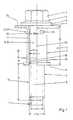
- FIG. 1is a side view of a first exemplary embodiment of the novel fastener including a bush-like supporting element.
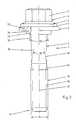
- FIG. 2is a side view of a second exemplary embodiment of the novel fastener including a disk-like supporting element.
- FIG. 3is a partial view of another exemplary embodiment of the novel fastener.
- FIG. 4is a partial view of another exemplary embodiment of the novel fastener.
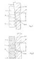
- FIG. 5is a semi-sectional enlarged view of a common thread runout and a supporting element (prior art).
- FIG. 6is a semi-sectional enlarged view of the novel supporting element surrounding the thread runout.
- FIG. 7is a semi-sectional enlarged view of another exemplary embodiment of the novel fastener illustrating the principles of enveloping the thread runout by the supporting element.
- FIG. 8is a view of another exemplary embodiment of the novel fastener.
- FIG. 9is a view of another exemplary embodiment of the novel fastener.
- FIG. 1illustrates a first exemplary of the novel fastener 1 .
- the fastener 1 or fastener assemblyincludes two or more components. Especially, it includes a screw 2 and a supporting element 3 .
- the screw 2is designed as a collar screw. However, it may also have a different design.
- the screw 2includes a head 4 including an engagement surface 5 for a torsional tool for operating the screw and a collar 6 including a supporting surface 7 serving to transmit an axial force onto a component (not illustrated).
- a shank 8extends from the head 4 and from its supporting surface 7 , respectively, to the free end 9 of the screw 2 .
- the shank 8 in the region of the free end 9may include a centering portion.
- the shank 8 at its side facing the head 4includes a shank portion 10 having a diameter 11 which is less or smaller than the diameter of a thread to be described herein below.
- a threaded portion 12is located in the region of the end 9 of the screw 2 . However, it may also be located at a different place of the screw 2 , for example in a middle portion of the shank 8 or close to the head 4 .
- the thread of the threaded portion 12has a core diameter 13 and an outer diameter 14 .
- a thread runout 15 (or an end of the thread) facing the head 4 of the screw 2is located between the shank portion 10 having the diameter 11 and the threaded portion 12 .
- the end of the thread 15extends along the screw 2 about a length 16 .
- the threaded portion 12 including the opposite end of the thread facing the free end 9has a length 17 .
- the thread runout 15forms a (truncated) cone 18 .
- the thread runout 15has a conical design at this place. This means that it has the shape of a (truncated) cone 18 .
- the cone 18 of a comparatively long thread runout 15 (“normal design”)is respectively longer than the one of a comparatively shorter thread runout 15 (“short design”).
- the cone 18usually has a cone angle 19 ( FIG. 6 ) of approximately 8°.
- the reduced diameter 11 of the shank portion 10usually has a value between the core diameter 13 and the outer diameter 14 of the threaded portion 12 .
- the shank portion 10extends along a length 20 starting at the supporting surface 7 of the head of the screw 2 and ending at the beginning of the end of the thread 15 facing the head 4 of the screw 2 .
- the screw 2has a usual design known from the prior art.
- the novel supporting element 3 illustrated in FIG. 1is designed as a bush 21 having the shape of a hollow cylinder. It has an inner diameter 23 , and it is arranged in a way to be approximately symmetrical with respect to the axis 22 of the screw 2 . In the illustrated embodiment, the inner diameter 23 is greater than the outer diameter 14 of the threaded portion 12 such that the bush 21 may be pushed upon the shank 8 of the screw 2 after having produced the thread of the threaded portion 12 .
- the bush 21 at its two endsmay include flanges 24 and 25 extending in a radial direction.
- the bush 21has a length 26 extending in an axial direction, meaning parallel to the axis 22 .
- the length 26is greater than the sum of the lengths 16 and 20 such that the bush 21 ends in the region of the end of the thread 15 .
- the length 26may also be chosen to be shorter to allow for screwing over the threaded portion 12 . Due to the chosen diameters, the bush 21 and the supporting element 3 , respectively, may be rotated with respect to the screw 2 .
- the supporting element 3includes a narrow location 27 or narrowing having a diameter 28 which is smaller than the outer diameter 14 of the threaded portion 12 .
- the narrow location 27may be formed by a plurality of impressions 29 .
- the impressions 29may be produced after having rolled the thread of the threaded portion 12 and after having pushed the bush 21 onto the screw 2 .
- the impressions 29being located at the inner diameter 23 of the bush 21 include surface elements 30 , and they form these surface elements 30 or contact elements, respectively.
- These elements 30are part of a (incomplete) surrounding cone or enveloping cone 31 , and they together form such an enveloping cone 31 (FIG. 6 ), respectively.
- the enveloping cone 31has a cone angle 32 .
- the narrow location 27may also be designed in a different way, for example, by one continuous protrusion protruding inwardly towards the screw, by an inclined surface being part of a truncated cone and the like.
- the supporting element of the novel fastenerincludes impressions 29 forming surface elements 30 being part of an enveloping cone 31 , the surface elements 30 facing and being associated with the end of the thread 15 of the screw 2 .
- the (incomplete) enveloping cone 31being formed by the surface elements 30 of the impressions 29 envelopes the (truncated) cone 18 of the end of the thread 15 , as it is to be seen in FIG. 6 .
- the cone angle 19 of the cone 18 of the end of the thread 15usually is in a range of approximately 8°.
- the cone angle 32 of the enveloping cone 31is chosen to have approximately the same angle, or to be less.
- FIG. 6illustrates a smaller cone angle 32 of a value of approximately between 3° and 8°.
- the cone angle 32may have a value of 5°. Due to the coordinated design of the end of the thread 15 of the screw 2 and the impressions 29 with the surface elements 30 of the supporting element 3 and the resulting enveloping cone 31 , one achieves punctual support of the supporting element 3 at the end of the thread 15 when the novel fastener 1 with its head 4 is transported in an upward direction, and when a transporting or conveying element engages the supporting surface 7 being located at the head 4 of the screw 2 . Consequently, clamping of the supporting element 3 at the screw 2 is securely prevented. During assembly of the fastener 1 , the supporting element 3 automatically takes the desired relative position by the flange 24 contacting the supporting surface 7 .
- FIG. 2illustrates another exemplary embodiment of the novel fastener 1 including a screw 2 .
- the supporting element 3is designed as a disk 33 .
- the disk 33includes a collar-like protrusion 34 extending in an axial direction.
- the protrusion 34 at its inner surfaceincludes a continuous inclined surface 35 .
- This surface 35fulfills the same function as the surface elements 30 of the embodiment according to FIG. 1 .
- the surface 35is also located on the enveloping cone 31 at the cone angle 32 .
- the screw 2is produced as a separate element, the shank 8 having the rolling diameter along its entire length.
- the supporting element 3 in the form of a disk 33is produced to reach its final properties.
- the surface of the disk 33is produced such that it reaches the desired final properties. This includes the inclined surface 35 .
- a thread 36is produced in the region of the threaded portion 12 of the thread 2 by rolling and by thread rolling, respectively.
- the thread 36includes the end of the thread 15 . Due to the production of the threads of the thread 36 , material of the shank 8 of the screw 2 is displaced in a radial direction towards the outside such that the outer diameter 14 of the threaded portion 12 is attained. The outer diameter 14 is greater than the inner diameter of the disk 33 . In this way, the supporting element 3 is connected to the screw 2 in a captive and rotatable way. Rolling of the thread 36 is especially simple when the disk 33 only has a comparatively short axial length. Rolling is especially simple when the length of the disk 33 is less than the length of the shank portion 10 of the shank 8 having a reduced diameter.
- the embodiment of the novel fastener 1 illustrated in FIGS. 3 and 4also include a supporting element 3 being designed as a disk 33 .
- the disk 33is designed as plain washer, meaning such that it does not include collar-like protrusions (see the protrusion 34 in FIG. 2 ).
- the inclined surface 35 of the disk 33extends along the entire thickness of the disk 33 .
- the disk 33consequently has a cone-like opening or a truncated cone-like opening being part of the enveloping cone 31 .
- the inclined surface 35only extends along a middle portion of the axial extension of the disk 33 .
- the disk 33 at its upper side facing the head 4 of the screw 2includes a recess 37 .
- the recess 37is coordinated with the transition radius of the shank portion 10 and the supporting surface 7 .
- the inclined surface 35may directly contact the bottom side of the disk 33 .
- the inclined surface 35may be connected to a cylindrical portion 38 (as illustrated in FIG. 4 ).
- the cylindrical portion 38has an inner diameter which is greater than the outer diameter of the threaded portion 12 to prevent clamping of the cylindrical portion 38 with respect to the end of the thread 15 .
- FIG. 5illustrates a prior art fastener.
- FIG. 5is a semi-sectional view at an enlarged scale of a part of the screw 2 including the end of the thread 15 and the thread 36 of the threaded portion 12 .
- the end of the thread 15extends in an axial direction between the shank portion 10 having a reduced diameter and the threaded portion 12 .
- a part of a bush 21 and of a supporting element 3is illustrated in association with the shank portion 10 .
- the supporting element 3 of the prior art fastenerincludes impressions 39 being located approximately in the middle region of its axial extension and being spaced apart the circumference.
- the impressions 39are produced by pressing from the outside towards the inside.
- the impressions 39have a surface 40 protruding in a radial inward direction and being similar to a ball.
- the surface 40may also be designed to have a slightly rounded design.
- the surface 40 in the prior artis always designed such that it engages an impression 41 being located between two adjacent threads of the end of the thread 15 . In this way, the prior art supporting element 3 as illustrated in FIG. 5 is clamped at the end of the thread 15 of the screw 2 , and it interlocks with the end of the thread 15 , respectively.
- FIG. 6illustrates the novel fastener 1 including the surface elements 30 and the inclined surface 35 , respectively, as being a component of the enveloping cone 31 having a smaller cone angle 32 . It is to be seen from FIG. 6 that the cone 18 or truncated cone of the thread runout 15 only punctually contacts the end of the thread 15 . At the most, there may be line contact. The limit for the cone angle 32 is determined by self-locking effects.
- FIG. 6illustrates the supporting element 3 as being designed as a bush 21 , the same applies to the supporting element 3 being designed as a disk 33 .
- FIG. 7illustrates another possible exemplary embodiment of the novel fastener 1 .
- the supporting element 3may include local impressions 29 forming the surface elements 30 .
- FIG. 7makes it clear that the surface element 30 and the inclined surface 35 , respectively, preferably has a length 42 which preferably is not less than the lead of the thread of the threaded portion 12 and of the thread 15 runout, respectively. To be exact, the length 42 extends in the direction of the surface of the cone.
- the lead of the thread runout 15is indicated by dot and dash lines in FIG. 7 . The lead is to be understood as the distance between two dot and dash lines.
- the illustrated exemplary embodiment of the novel fastener 1is chosen such that the length 42 of the supporting element 3 is slightly greater than double value of the lead of the thread of the screw 2 .
- the surface elements 30 and the inclined surface 35are part of the enveloping cone 31 having the cone angle 32 .
- the surface element 30 and the inclined surface 35respectively, at its end facing the lower end 9 of the screw 2 is directly connected to the inner diameter of the bush 21 and of the supporting element 3 , respectively.
- the enveloping cone 31 in the illustrated exemplary embodiment of the fastener 1has such a length which is greater than the length of the thread runout 25 . This means that the enveloping cone 31 completely covers the thread runout 25 .
- FIG. 8illustrates a slightly different exemplary embodiment of the novel fastener 1 .
- the radial deformation of the supporting element 3is emphasized compared to the embodiment according to FIG. 7 such that there is greater clearance between the bush 21 and the outer diameter 14 of the threaded portion 12 .
- FIG. 9illustrates another exemplary embodiment of the novel fastener 1 being similar to the one illustrated in FIG. 1 . Consequently, it is referred to the above description related to FIG. 1 .
- the fastener 1 illustrated in FIG. 9includes a supporting element 3 with two flanges 24 and 25 .
- the flanges 24 and 25serve to support and to arrange an elastomer element 43 extending along the entire length between the flanges 24 and 25 .
- the novel fastener 1may serve for soundproof fixing purposes. Support on a component is realized in the middle portion of the elastomer element 43 such that the bush 3 does not have to transmit an axial force.
- the elastomer element 43does not necessarily have to extend along the entire length between the flanges 24 and 25 , but it may also be designed to be shorter. Furthermore, it is possible to design the screw 2 as a center collar screw, meaning to arrange another functional element at the head 4 . All these different embodiments may be used in connection with the present invention.
Landscapes
- Engineering & Computer Science (AREA)
- General Engineering & Computer Science (AREA)
- Mechanical Engineering (AREA)
- Dowels (AREA)
- Electric Double-Layer Capacitors Or The Like (AREA)
- Furniture Connections (AREA)
- Coupling Device And Connection With Printed Circuit (AREA)
Abstract
Description
Claims (17)
Applications Claiming Priority (2)
| Application Number | Priority Date | Filing Date | Title |
|---|---|---|---|
| DE10215883ADE10215883B4 (en) | 2002-04-11 | 2002-04-11 | Connecting element with a screw and a captive arranged support element |
| DE10215883.5 | 2002-04-11 |
Publications (2)
| Publication Number | Publication Date |
|---|---|
| US20030194292A1 US20030194292A1 (en) | 2003-10-16 |
| US6872040B2true US6872040B2 (en) | 2005-03-29 |
Family
ID=28051242
Family Applications (1)
| Application Number | Title | Priority Date | Filing Date |
|---|---|---|---|
| US10/412,162Expired - LifetimeUS6872040B2 (en) | 2002-04-11 | 2003-04-11 | Fastener including a screw and a supporting element |
Country Status (5)
| Country | Link |
|---|---|
| US (1) | US6872040B2 (en) |
| EP (1) | EP1353081B1 (en) |
| AT (1) | ATE287503T1 (en) |
| DE (2) | DE10215883B4 (en) |
| ES (1) | ES2233890T3 (en) |
Cited By (80)
| Publication number | Priority date | Publication date | Assignee | Title |
|---|---|---|---|---|
| US20050025566A1 (en)* | 2003-07-29 | 2005-02-03 | Aoyama Seisakusho Co., Ltd. | Fastening device |
| US20050120667A1 (en)* | 2003-12-04 | 2005-06-09 | Bruce Mead | Captive fastener |
| US20060190042A1 (en)* | 2004-11-05 | 2006-08-24 | Arthrotek, Inc. | Tissue repair assembly |
| US20080075403A1 (en)* | 2006-09-27 | 2008-03-27 | Jason Holt | Work Piece Isolating Assembly |
| US20080095593A1 (en)* | 2006-10-18 | 2008-04-24 | Mclean Shawn G | Compression Limiter |
| US20090123252A1 (en)* | 2007-11-14 | 2009-05-14 | Newfrey Llc | Power Seal Bolt Assembly |
| US20090232618A1 (en)* | 2008-03-13 | 2009-09-17 | The Timken Company | Fastener assembly |
| US7601165B2 (en) | 2006-09-29 | 2009-10-13 | Biomet Sports Medicine, Llc | Method and apparatus for forming a self-locking adjustable suture loop |
| US7608098B1 (en) | 2004-11-09 | 2009-10-27 | Biomet Sports Medicine, Llc | Bone fixation device |
| US7608092B1 (en) | 2004-02-20 | 2009-10-27 | Biomet Sports Medicince, LLC | Method and apparatus for performing meniscus repair |
| US7749250B2 (en) | 2006-02-03 | 2010-07-06 | Biomet Sports Medicine, Llc | Soft tissue repair assembly and associated method |
| US20100212277A1 (en)* | 2009-02-20 | 2010-08-26 | Marrs William R | Crop harvester |
| US7857830B2 (en) | 2006-02-03 | 2010-12-28 | Biomet Sports Medicine, Llc | Soft tissue repair and conduit device |
| US7905903B2 (en) | 2006-02-03 | 2011-03-15 | Biomet Sports Medicine, Llc | Method for tissue fixation |
| US7905904B2 (en) | 2006-02-03 | 2011-03-15 | Biomet Sports Medicine, Llc | Soft tissue repair device and associated methods |
| US7909851B2 (en) | 2006-02-03 | 2011-03-22 | Biomet Sports Medicine, Llc | Soft tissue repair device and associated methods |
| US7914539B2 (en) | 2004-11-09 | 2011-03-29 | Biomet Sports Medicine, Llc | Tissue fixation device |
| US7959650B2 (en) | 2006-09-29 | 2011-06-14 | Biomet Sports Medicine, Llc | Adjustable knotless loops |
| US8034090B2 (en) | 2004-11-09 | 2011-10-11 | Biomet Sports Medicine, Llc | Tissue fixation device |
| US8088130B2 (en) | 2006-02-03 | 2012-01-03 | Biomet Sports Medicine, Llc | Method and apparatus for coupling soft tissue to a bone |
| US8118836B2 (en) | 2004-11-05 | 2012-02-21 | Biomet Sports Medicine, Llc | Method and apparatus for coupling soft tissue to a bone |
| US8128658B2 (en) | 2004-11-05 | 2012-03-06 | Biomet Sports Medicine, Llc | Method and apparatus for coupling soft tissue to bone |
| US8137382B2 (en) | 2004-11-05 | 2012-03-20 | Biomet Sports Medicine, Llc | Method and apparatus for coupling anatomical features |
| US8251998B2 (en) | 2006-08-16 | 2012-08-28 | Biomet Sports Medicine, Llc | Chondral defect repair |
| US8298262B2 (en) | 2006-02-03 | 2012-10-30 | Biomet Sports Medicine, Llc | Method for tissue fixation |
| US8303604B2 (en) | 2004-11-05 | 2012-11-06 | Biomet Sports Medicine, Llc | Soft tissue repair device and method |
| US8317825B2 (en) | 2004-11-09 | 2012-11-27 | Biomet Sports Medicine, Llc | Soft tissue conduit device and method |
| US8343227B2 (en) | 2009-05-28 | 2013-01-01 | Biomet Manufacturing Corp. | Knee prosthesis assembly with ligament link |
| US8361113B2 (en) | 2006-02-03 | 2013-01-29 | Biomet Sports Medicine, Llc | Method and apparatus for coupling soft tissue to a bone |
| US20130121786A1 (en)* | 2011-11-11 | 2013-05-16 | Volvo Car Corporation | Screw assembly element |
| US8500818B2 (en) | 2006-09-29 | 2013-08-06 | Biomet Manufacturing, Llc | Knee prosthesis assembly with ligament link |
| US8506597B2 (en) | 2011-10-25 | 2013-08-13 | Biomet Sports Medicine, Llc | Method and apparatus for interosseous membrane reconstruction |
| US8562645B2 (en) | 2006-09-29 | 2013-10-22 | Biomet Sports Medicine, Llc | Method and apparatus for forming a self-locking adjustable loop |
| US8562647B2 (en) | 2006-09-29 | 2013-10-22 | Biomet Sports Medicine, Llc | Method and apparatus for securing soft tissue to bone |
| US8574235B2 (en) | 2006-02-03 | 2013-11-05 | Biomet Sports Medicine, Llc | Method for trochanteric reattachment |
| US8597327B2 (en) | 2006-02-03 | 2013-12-03 | Biomet Manufacturing, Llc | Method and apparatus for sternal closure |
| US8641341B2 (en) | 2010-04-14 | 2014-02-04 | Koyo Bearings Usa Llc | Bolt retention apparatus and method |
| US8652172B2 (en) | 2006-02-03 | 2014-02-18 | Biomet Sports Medicine, Llc | Flexible anchors for tissue fixation |
| US8652171B2 (en) | 2006-02-03 | 2014-02-18 | Biomet Sports Medicine, Llc | Method and apparatus for soft tissue fixation |
| US8672969B2 (en) | 2006-09-29 | 2014-03-18 | Biomet Sports Medicine, Llc | Fracture fixation device |
| US8771352B2 (en) | 2011-05-17 | 2014-07-08 | Biomet Sports Medicine, Llc | Method and apparatus for tibial fixation of an ACL graft |
| US8801783B2 (en) | 2006-09-29 | 2014-08-12 | Biomet Sports Medicine, Llc | Prosthetic ligament system for knee joint |
| US8840645B2 (en) | 2004-11-05 | 2014-09-23 | Biomet Sports Medicine, Llc | Method and apparatus for coupling soft tissue to a bone |
| US8936621B2 (en) | 2006-02-03 | 2015-01-20 | Biomet Sports Medicine, Llc | Method and apparatus for forming a self-locking adjustable loop |
| US8968364B2 (en) | 2006-02-03 | 2015-03-03 | Biomet Sports Medicine, Llc | Method and apparatus for fixation of an ACL graft |
| US8998949B2 (en) | 2004-11-09 | 2015-04-07 | Biomet Sports Medicine, Llc | Soft tissue conduit device |
| US9017381B2 (en) | 2007-04-10 | 2015-04-28 | Biomet Sports Medicine, Llc | Adjustable knotless loops |
| US9078644B2 (en) | 2006-09-29 | 2015-07-14 | Biomet Sports Medicine, Llc | Fracture fixation device |
| US9149267B2 (en) | 2006-02-03 | 2015-10-06 | Biomet Sports Medicine, Llc | Method and apparatus for coupling soft tissue to a bone |
| US9259217B2 (en) | 2012-01-03 | 2016-02-16 | Biomet Manufacturing, Llc | Suture Button |
| US9271713B2 (en) | 2006-02-03 | 2016-03-01 | Biomet Sports Medicine, Llc | Method and apparatus for tensioning a suture |
| US9314241B2 (en) | 2011-11-10 | 2016-04-19 | Biomet Sports Medicine, Llc | Apparatus for coupling soft tissue to a bone |
| US9357991B2 (en) | 2011-11-03 | 2016-06-07 | Biomet Sports Medicine, Llc | Method and apparatus for stitching tendons |
| US9370350B2 (en) | 2011-11-10 | 2016-06-21 | Biomet Sports Medicine, Llc | Apparatus for coupling soft tissue to a bone |
| US9381013B2 (en) | 2011-11-10 | 2016-07-05 | Biomet Sports Medicine, Llc | Method for coupling soft tissue to a bone |
| US9538998B2 (en) | 2006-02-03 | 2017-01-10 | Biomet Sports Medicine, Llc | Method and apparatus for fracture fixation |
| US9615822B2 (en) | 2014-05-30 | 2017-04-11 | Biomet Sports Medicine, Llc | Insertion tools and method for soft anchor |
| CN106884844A (en)* | 2017-02-24 | 2017-06-23 | 郑州云海信息技术有限公司 | A kind of bolt structure for assisting to position |
| US9700291B2 (en) | 2014-06-03 | 2017-07-11 | Biomet Sports Medicine, Llc | Capsule retractor |
| US9757119B2 (en) | 2013-03-08 | 2017-09-12 | Biomet Sports Medicine, Llc | Visual aid for identifying suture limbs arthroscopically |
| US9801708B2 (en) | 2004-11-05 | 2017-10-31 | Biomet Sports Medicine, Llc | Method and apparatus for coupling soft tissue to a bone |
| US9918827B2 (en) | 2013-03-14 | 2018-03-20 | Biomet Sports Medicine, Llc | Scaffold for spring ligament repair |
| US9918826B2 (en) | 2006-09-29 | 2018-03-20 | Biomet Sports Medicine, Llc | Scaffold for spring ligament repair |
| US9955980B2 (en) | 2015-02-24 | 2018-05-01 | Biomet Sports Medicine, Llc | Anatomic soft tissue repair |
| US10039543B2 (en) | 2014-08-22 | 2018-08-07 | Biomet Sports Medicine, Llc | Non-sliding soft anchor |
| US10113581B2 (en) | 2016-12-21 | 2018-10-30 | Fca Us Llc | Body isolator and bolt retention assembly |
| US10136886B2 (en) | 2013-12-20 | 2018-11-27 | Biomet Sports Medicine, Llc | Knotless soft tissue devices and techniques |
| US10184660B2 (en) | 2016-04-27 | 2019-01-22 | Copreci, S. Coop. | Gas distribution system and cooking appliance incorporating the gas distribution system |
| US10443553B2 (en) | 2011-03-04 | 2019-10-15 | Continental Automative Gmbh | Coupling device |
| US20190383315A1 (en)* | 2018-06-18 | 2019-12-19 | General Fasteners Company | Compression limiter fastener assembly |
| US10517587B2 (en) | 2006-02-03 | 2019-12-31 | Biomet Sports Medicine, Llc | Method and apparatus for forming a self-locking adjustable loop |
| US10912551B2 (en) | 2015-03-31 | 2021-02-09 | Biomet Sports Medicine, Llc | Suture anchor with soft anchor of electrospun fibers |
| US11259794B2 (en) | 2006-09-29 | 2022-03-01 | Biomet Sports Medicine, Llc | Method for implanting soft tissue |
| US11259792B2 (en) | 2006-02-03 | 2022-03-01 | Biomet Sports Medicine, Llc | Method and apparatus for coupling anatomical features |
| US11311287B2 (en) | 2006-02-03 | 2022-04-26 | Biomet Sports Medicine, Llc | Method for tissue fixation |
| US11486296B2 (en) | 2020-06-19 | 2022-11-01 | Mahle International Gmbh | Exhaust gas turbocharger assembly having an exhaust gas turbocharger and an actuator |
| US12096928B2 (en) | 2009-05-29 | 2024-09-24 | Biomet Sports Medicine, Llc | Method and apparatus for coupling soft tissue to a bone |
| US12245759B2 (en) | 2008-08-22 | 2025-03-11 | Biomet Sports Medicine, Llc | Method and apparatus for coupling soft tissue to bone |
| US12329373B2 (en) | 2011-05-02 | 2025-06-17 | Biomet Sports Medicine, Llc | Method and apparatus for soft tissue fixation |
| US12419632B2 (en) | 2008-08-22 | 2025-09-23 | Biomet Sports Medicine, Llc | Method and apparatus for coupling anatomical features |
Families Citing this family (11)
| Publication number | Priority date | Publication date | Assignee | Title |
|---|---|---|---|---|
| AU2003205378A1 (en)* | 2002-02-11 | 2003-09-04 | Pem Management, Inc. | Two-part snap-together panel fastener |
| US7306418B2 (en)* | 2004-09-27 | 2007-12-11 | General Motors Corporation | Deforming member and captive fastener retaining method |
| DE102008011271B3 (en)* | 2007-10-26 | 2009-05-28 | Richard Bergner Verbindungstechnik Gmbh & Co. Kg | Fixable to a basic construction assembly unit |
| DE102007047860B3 (en) | 2007-11-26 | 2008-12-18 | Kamax-Werke Rudolf Kellermann Gmbh & Co. Kg | Connecting element, e.g. for automobile, has bolt, non-removable sleeve with first narrow point, second narrow point with radially sprung element(s) that engage thread in force- and/or shape-locking manner and axially continuous slot or gap |
| DE102008029236B3 (en)* | 2008-06-19 | 2010-02-11 | Kamax-Werke Rudolf Kellermann Gmbh & Co. Kg | Connecting element with a screw and a captive arranged sleeve |
| KR101193248B1 (en)* | 2012-06-18 | 2012-10-18 | 동양기전 주식회사 | Bolt assembly for wiper apparatus of a vehicle |
| DE102012210369A1 (en)* | 2012-06-20 | 2013-12-24 | Robert Bosch Gmbh | Holder for fixing a fuel distributor to an internal combustion engine and fuel injection system with such a holder. |
| DE102015121479A1 (en) | 2015-12-10 | 2017-06-14 | Knorr-Bremse Systeme für Nutzfahrzeuge GmbH | connecting element |
| US11566655B2 (en)* | 2020-02-20 | 2023-01-31 | Caterpillar Inc. | Bolt retainer configuration to hold a position of a bolt within a component |
| US11654975B2 (en) | 2020-12-21 | 2023-05-23 | Am General Llc | Vehicle frame rails and methods of assembling vehicle frame rails |
| US12365396B1 (en) | 2021-08-02 | 2025-07-22 | Am General Llc | Vehicle frame rails with swaged spacer connection and methods of manufacturing vehicle frame rails |
Citations (15)
| Publication number | Priority date | Publication date | Assignee | Title |
|---|---|---|---|---|
| DE21072C (en) | C. WEIS in Dresden, Neustadt, Königstr. 16 | Innovations in ventilation devices on box windows | ||
| US2639179A (en)* | 1950-03-31 | 1953-05-19 | Weber Knapp Co | Self-aligning, screw-threaded fastening device |
| US2987811A (en)* | 1957-09-24 | 1961-06-13 | W F Curlee | Method of mounting a captive fastener |
| US3041913A (en)* | 1959-05-07 | 1962-07-03 | George W Liska | Eccentrically adjustable fastener |
| DE1812906A1 (en) | 1967-12-08 | 1969-07-03 | Du Pont | 4-phenylbicyclo [2.2.2] octane and oct-2-ene-1-carbinols and carboxaldehydes |
| US4212224A (en) | 1978-09-25 | 1980-07-15 | American Optical Corporation | Jacking screw type fastener |
| US4396327A (en)* | 1979-10-17 | 1983-08-02 | Erno Raumfahrttechnik Gmbh | Screw capture |
| US5040917A (en)* | 1989-03-30 | 1991-08-20 | Fiat Auto S.P.A. | Device for fixing mechanical parts to the body of a motor vehicle |
| US5489177A (en) | 1994-06-08 | 1996-02-06 | Crest Products, Inc. | Fastener assembly with axially captivated washer |
| DE19534034A1 (en) | 1995-09-14 | 1997-03-20 | Mann & Hummel Filter | Fastener device for components in motor industry |
| DE29711296U1 (en) | 1997-06-28 | 1997-08-28 | Robert Bosch Gmbh, 70469 Stuttgart | Arrangement for securing a fastener against loss |
| DE19750658C1 (en) | 1997-11-15 | 1999-03-11 | Gloeckler Dichtsysteme Guenter | Threaded connecting fastener |
| US6082942A (en)* | 1993-11-22 | 2000-07-04 | Swick; E. Grant | Electrical connection terminal assembly and tilt washer |
| DE19924502A1 (en) | 1999-05-28 | 2000-12-21 | Elringklinger Gmbh | Screw with sleeve |
| US6227783B1 (en)* | 2000-03-11 | 2001-05-08 | Federal-Mogul Sealing Systems Bretten Gmbh & Co., Kg | Fastener with retaining sleeve |
Family Cites Families (3)
| Publication number | Priority date | Publication date | Assignee | Title |
|---|---|---|---|---|
| DE1812906U (en)* | 1958-08-27 | 1960-06-09 | Walter Stueckrath | FUSE FOR SCREWS AGAINST FALLING OUT |
| DE6906647U (en)* | 1969-02-12 | 1969-11-27 | Miele & Cie | WASHER |
| US6082642A (en)* | 1999-02-01 | 2000-07-04 | Vieley; Robert J. | Apparatus and method for pulverizing compressible materials |
- 2002
- 2002-04-11DEDE10215883Apatent/DE10215883B4/ennot_activeExpired - Lifetime
- 2003
- 2003-04-04ATAT03007740Tpatent/ATE287503T1/enactive
- 2003-04-04DEDE50300257Tpatent/DE50300257D1/ennot_activeExpired - Lifetime
- 2003-04-04ESES03007740Tpatent/ES2233890T3/ennot_activeExpired - Lifetime
- 2003-04-04EPEP03007740Apatent/EP1353081B1/ennot_activeExpired - Lifetime
- 2003-04-11USUS10/412,162patent/US6872040B2/ennot_activeExpired - Lifetime
Patent Citations (15)
| Publication number | Priority date | Publication date | Assignee | Title |
|---|---|---|---|---|
| DE21072C (en) | C. WEIS in Dresden, Neustadt, Königstr. 16 | Innovations in ventilation devices on box windows | ||
| US2639179A (en)* | 1950-03-31 | 1953-05-19 | Weber Knapp Co | Self-aligning, screw-threaded fastening device |
| US2987811A (en)* | 1957-09-24 | 1961-06-13 | W F Curlee | Method of mounting a captive fastener |
| US3041913A (en)* | 1959-05-07 | 1962-07-03 | George W Liska | Eccentrically adjustable fastener |
| DE1812906A1 (en) | 1967-12-08 | 1969-07-03 | Du Pont | 4-phenylbicyclo [2.2.2] octane and oct-2-ene-1-carbinols and carboxaldehydes |
| US4212224A (en) | 1978-09-25 | 1980-07-15 | American Optical Corporation | Jacking screw type fastener |
| US4396327A (en)* | 1979-10-17 | 1983-08-02 | Erno Raumfahrttechnik Gmbh | Screw capture |
| US5040917A (en)* | 1989-03-30 | 1991-08-20 | Fiat Auto S.P.A. | Device for fixing mechanical parts to the body of a motor vehicle |
| US6082942A (en)* | 1993-11-22 | 2000-07-04 | Swick; E. Grant | Electrical connection terminal assembly and tilt washer |
| US5489177A (en) | 1994-06-08 | 1996-02-06 | Crest Products, Inc. | Fastener assembly with axially captivated washer |
| DE19534034A1 (en) | 1995-09-14 | 1997-03-20 | Mann & Hummel Filter | Fastener device for components in motor industry |
| DE29711296U1 (en) | 1997-06-28 | 1997-08-28 | Robert Bosch Gmbh, 70469 Stuttgart | Arrangement for securing a fastener against loss |
| DE19750658C1 (en) | 1997-11-15 | 1999-03-11 | Gloeckler Dichtsysteme Guenter | Threaded connecting fastener |
| DE19924502A1 (en) | 1999-05-28 | 2000-12-21 | Elringklinger Gmbh | Screw with sleeve |
| US6227783B1 (en)* | 2000-03-11 | 2001-05-08 | Federal-Mogul Sealing Systems Bretten Gmbh & Co., Kg | Fastener with retaining sleeve |
Cited By (206)
| Publication number | Priority date | Publication date | Assignee | Title |
|---|---|---|---|---|
| US20050025566A1 (en)* | 2003-07-29 | 2005-02-03 | Aoyama Seisakusho Co., Ltd. | Fastening device |
| US7488135B2 (en)* | 2003-07-29 | 2009-02-10 | Aoyama Seisakusho Co., Ltd. | Fastening device |
| US20050120667A1 (en)* | 2003-12-04 | 2005-06-09 | Bruce Mead | Captive fastener |
| US7608092B1 (en) | 2004-02-20 | 2009-10-27 | Biomet Sports Medicince, LLC | Method and apparatus for performing meniscus repair |
| US8221454B2 (en) | 2004-02-20 | 2012-07-17 | Biomet Sports Medicine, Llc | Apparatus for performing meniscus repair |
| US8303604B2 (en) | 2004-11-05 | 2012-11-06 | Biomet Sports Medicine, Llc | Soft tissue repair device and method |
| US8137382B2 (en) | 2004-11-05 | 2012-03-20 | Biomet Sports Medicine, Llc | Method and apparatus for coupling anatomical features |
| US9801708B2 (en) | 2004-11-05 | 2017-10-31 | Biomet Sports Medicine, Llc | Method and apparatus for coupling soft tissue to a bone |
| US9572655B2 (en) | 2004-11-05 | 2017-02-21 | Biomet Sports Medicine, Llc | Method and apparatus for coupling soft tissue to a bone |
| US8118836B2 (en) | 2004-11-05 | 2012-02-21 | Biomet Sports Medicine, Llc | Method and apparatus for coupling soft tissue to a bone |
| US8128658B2 (en) | 2004-11-05 | 2012-03-06 | Biomet Sports Medicine, Llc | Method and apparatus for coupling soft tissue to bone |
| US9504460B2 (en) | 2004-11-05 | 2016-11-29 | Biomet Sports Medicine, LLC. | Soft tissue repair device and method |
| US20060190042A1 (en)* | 2004-11-05 | 2006-08-24 | Arthrotek, Inc. | Tissue repair assembly |
| US10265064B2 (en) | 2004-11-05 | 2019-04-23 | Biomet Sports Medicine, Llc | Soft tissue repair device and method |
| US8551140B2 (en) | 2004-11-05 | 2013-10-08 | Biomet Sports Medicine, Llc | Method and apparatus for coupling soft tissue to bone |
| US8840645B2 (en) | 2004-11-05 | 2014-09-23 | Biomet Sports Medicine, Llc | Method and apparatus for coupling soft tissue to a bone |
| US11109857B2 (en) | 2004-11-05 | 2021-09-07 | Biomet Sports Medicine, Llc | Soft tissue repair device and method |
| US8998949B2 (en) | 2004-11-09 | 2015-04-07 | Biomet Sports Medicine, Llc | Soft tissue conduit device |
| US8317825B2 (en) | 2004-11-09 | 2012-11-27 | Biomet Sports Medicine, Llc | Soft tissue conduit device and method |
| US8034090B2 (en) | 2004-11-09 | 2011-10-11 | Biomet Sports Medicine, Llc | Tissue fixation device |
| US7608098B1 (en) | 2004-11-09 | 2009-10-27 | Biomet Sports Medicine, Llc | Bone fixation device |
| US7914539B2 (en) | 2004-11-09 | 2011-03-29 | Biomet Sports Medicine, Llc | Tissue fixation device |
| US10729430B2 (en) | 2006-02-03 | 2020-08-04 | Biomet Sports Medicine, Llc | Method and apparatus for coupling soft tissue to a bone |
| US11617572B2 (en) | 2006-02-03 | 2023-04-04 | Biomet Sports Medicine, Llc | Soft tissue repair device and associated methods |
| US8088130B2 (en) | 2006-02-03 | 2012-01-03 | Biomet Sports Medicine, Llc | Method and apparatus for coupling soft tissue to a bone |
| US7909851B2 (en) | 2006-02-03 | 2011-03-22 | Biomet Sports Medicine, Llc | Soft tissue repair device and associated methods |
| US7905904B2 (en) | 2006-02-03 | 2011-03-15 | Biomet Sports Medicine, Llc | Soft tissue repair device and associated methods |
| US7905903B2 (en) | 2006-02-03 | 2011-03-15 | Biomet Sports Medicine, Llc | Method for tissue fixation |
| US7857830B2 (en) | 2006-02-03 | 2010-12-28 | Biomet Sports Medicine, Llc | Soft tissue repair and conduit device |
| US10517587B2 (en) | 2006-02-03 | 2019-12-31 | Biomet Sports Medicine, Llc | Method and apparatus for forming a self-locking adjustable loop |
| US10932770B2 (en) | 2006-02-03 | 2021-03-02 | Biomet Sports Medicine, Llc | Soft tissue repair device and associated methods |
| US8273106B2 (en) | 2006-02-03 | 2012-09-25 | Biomet Sports Medicine, Llc | Soft tissue repair and conduit device |
| US8292921B2 (en) | 2006-02-03 | 2012-10-23 | Biomet Sports Medicine, Llc | Soft tissue repair device and associated methods |
| US8298262B2 (en) | 2006-02-03 | 2012-10-30 | Biomet Sports Medicine, Llc | Method for tissue fixation |
| US12096931B2 (en) | 2006-02-03 | 2024-09-24 | Biomet Sports Medicine, Llc | Method and apparatus for coupling soft tissue to a bone |
| US12064101B2 (en) | 2006-02-03 | 2024-08-20 | Biomet Sports Medicine, Llc | Method and apparatus for forming a self-locking adjustable loop |
| US8337525B2 (en) | 2006-02-03 | 2012-12-25 | Biomet Sports Medicine, Llc | Soft tissue repair device and associated methods |
| US11998185B2 (en) | 2006-02-03 | 2024-06-04 | Biomet Sports Medicine, Llc | Method and apparatus for coupling soft tissue to a bone |
| US8361113B2 (en) | 2006-02-03 | 2013-01-29 | Biomet Sports Medicine, Llc | Method and apparatus for coupling soft tissue to a bone |
| US8409253B2 (en) | 2006-02-03 | 2013-04-02 | Biomet Sports Medicine, Llc | Soft tissue repair assembly and associated method |
| US11896210B2 (en) | 2006-02-03 | 2024-02-13 | Biomet Sports Medicine, Llc | Method and apparatus for coupling soft tissue to a bone |
| US10595851B2 (en) | 2006-02-03 | 2020-03-24 | Biomet Sports Medicine, Llc | Method and apparatus for coupling soft tissue to a bone |
| US11819205B2 (en) | 2006-02-03 | 2023-11-21 | Biomet Sports Medicine, Llc | Soft tissue repair device and associated methods |
| US7749250B2 (en) | 2006-02-03 | 2010-07-06 | Biomet Sports Medicine, Llc | Soft tissue repair assembly and associated method |
| US10603029B2 (en) | 2006-02-03 | 2020-03-31 | Biomet Sports Medicine, Llc | Method and apparatus for coupling soft tissue to bone |
| US10441264B2 (en) | 2006-02-03 | 2019-10-15 | Biomet Sports Medicine, Llc | Soft tissue repair assembly and associated method |
| US8574235B2 (en) | 2006-02-03 | 2013-11-05 | Biomet Sports Medicine, Llc | Method for trochanteric reattachment |
| US8597327B2 (en) | 2006-02-03 | 2013-12-03 | Biomet Manufacturing, Llc | Method and apparatus for sternal closure |
| US8608777B2 (en) | 2006-02-03 | 2013-12-17 | Biomet Sports Medicine | Method and apparatus for coupling soft tissue to a bone |
| US8632569B2 (en) | 2006-02-03 | 2014-01-21 | Biomet Sports Medicine, Llc | Soft tissue repair device and associated methods |
| US11786236B2 (en) | 2006-02-03 | 2023-10-17 | Biomet Sports Medicine, Llc | Method and apparatus for coupling anatomical features |
| US8652172B2 (en) | 2006-02-03 | 2014-02-18 | Biomet Sports Medicine, Llc | Flexible anchors for tissue fixation |
| US8652171B2 (en) | 2006-02-03 | 2014-02-18 | Biomet Sports Medicine, Llc | Method and apparatus for soft tissue fixation |
| US10398428B2 (en) | 2006-02-03 | 2019-09-03 | Biomet Sports Medicine, Llc | Method and apparatus for coupling anatomical features |
| US10675073B2 (en) | 2006-02-03 | 2020-06-09 | Biomet Sports Medicine, Llc | Method and apparatus for sternal closure |
| US8721684B2 (en) | 2006-02-03 | 2014-05-13 | Biomet Sports Medicine, Llc | Method and apparatus for coupling anatomical features |
| US11730464B2 (en) | 2006-02-03 | 2023-08-22 | Biomet Sports Medicine, Llc | Soft tissue repair assembly and associated method |
| US11723648B2 (en) | 2006-02-03 | 2023-08-15 | Biomet Sports Medicine, Llc | Method and apparatus for soft tissue fixation |
| US8771316B2 (en) | 2006-02-03 | 2014-07-08 | Biomet Sports Medicine, Llc | Method and apparatus for coupling anatomical features |
| US9801620B2 (en) | 2006-02-03 | 2017-10-31 | Biomet Sports Medicine, Llc | Method and apparatus for coupling soft tissue to bone |
| US10687803B2 (en) | 2006-02-03 | 2020-06-23 | Biomet Sports Medicine, Llc | Method and apparatus for coupling soft tissue to a bone |
| US10321906B2 (en) | 2006-02-03 | 2019-06-18 | Biomet Sports Medicine, Llc | Method for tissue fixation |
| US10695052B2 (en) | 2006-02-03 | 2020-06-30 | Biomet Sports Medicine, Llc | Method and apparatus for coupling soft tissue to a bone |
| US8932331B2 (en) | 2006-02-03 | 2015-01-13 | Biomet Sports Medicine, Llc | Method and apparatus for coupling soft tissue to bone |
| US8936621B2 (en) | 2006-02-03 | 2015-01-20 | Biomet Sports Medicine, Llc | Method and apparatus for forming a self-locking adjustable loop |
| US8968364B2 (en) | 2006-02-03 | 2015-03-03 | Biomet Sports Medicine, Llc | Method and apparatus for fixation of an ACL graft |
| US10987099B2 (en) | 2006-02-03 | 2021-04-27 | Biomet Sports Medicine, Llc | Method for tissue fixation |
| US9005287B2 (en) | 2006-02-03 | 2015-04-14 | Biomet Sports Medicine, Llc | Method for bone reattachment |
| US10973507B2 (en) | 2006-02-03 | 2021-04-13 | Biomet Sports Medicine, Llc | Method and apparatus for coupling soft tissue to a bone |
| US10251637B2 (en) | 2006-02-03 | 2019-04-09 | Biomet Sports Medicine, Llc | Soft tissue repair device and associated methods |
| US9149267B2 (en) | 2006-02-03 | 2015-10-06 | Biomet Sports Medicine, Llc | Method and apparatus for coupling soft tissue to a bone |
| US9173651B2 (en) | 2006-02-03 | 2015-11-03 | Biomet Sports Medicine, Llc | Soft tissue repair device and associated methods |
| US11589859B2 (en) | 2006-02-03 | 2023-02-28 | Biomet Sports Medicine, Llc | Method and apparatus for coupling soft tissue to bone |
| US11471147B2 (en) | 2006-02-03 | 2022-10-18 | Biomet Sports Medicine, Llc | Method and apparatus for coupling soft tissue to a bone |
| US9271713B2 (en) | 2006-02-03 | 2016-03-01 | Biomet Sports Medicine, Llc | Method and apparatus for tensioning a suture |
| US11446019B2 (en) | 2006-02-03 | 2022-09-20 | Biomet Sports Medicine, Llc | Method and apparatus for coupling soft tissue to a bone |
| US10702259B2 (en) | 2006-02-03 | 2020-07-07 | Biomet Sports Medicine, Llc | Soft tissue repair assembly and associated method |
| US11317907B2 (en) | 2006-02-03 | 2022-05-03 | Biomet Sports Medicine, Llc | Method and apparatus for forming a self-locking adjustable loop |
| US11311287B2 (en) | 2006-02-03 | 2022-04-26 | Biomet Sports Medicine, Llc | Method for tissue fixation |
| US11284884B2 (en) | 2006-02-03 | 2022-03-29 | Biomet Sports Medicine, Llc | Method and apparatus for coupling soft tissue to a bone |
| US9402621B2 (en) | 2006-02-03 | 2016-08-02 | Biomet Sports Medicine, LLC. | Method for tissue fixation |
| US11259792B2 (en) | 2006-02-03 | 2022-03-01 | Biomet Sports Medicine, Llc | Method and apparatus for coupling anatomical features |
| US9414833B2 (en) | 2006-02-03 | 2016-08-16 | Biomet Sports Medicine, Llc | Soft tissue repair assembly and associated method |
| US10542967B2 (en) | 2006-02-03 | 2020-01-28 | Biomet Sports Medicine, Llc | Method and apparatus for coupling soft tissue to a bone |
| US10154837B2 (en) | 2006-02-03 | 2018-12-18 | Biomet Sports Medicine, Llc | Method and apparatus for coupling soft tissue to a bone |
| US11116495B2 (en) | 2006-02-03 | 2021-09-14 | Biomet Sports Medicine, Llc | Soft tissue repair assembly and associated method |
| US9468433B2 (en) | 2006-02-03 | 2016-10-18 | Biomet Sports Medicine, Llc | Method and apparatus for forming a self-locking adjustable loop |
| US10716557B2 (en) | 2006-02-03 | 2020-07-21 | Biomet Sports Medicine, Llc | Method and apparatus for coupling anatomical features |
| US9492158B2 (en) | 2006-02-03 | 2016-11-15 | Biomet Sports Medicine, Llc | Method and apparatus for coupling soft tissue to a bone |
| US9498204B2 (en) | 2006-02-03 | 2016-11-22 | Biomet Sports Medicine, Llc | Method and apparatus for coupling anatomical features |
| US10729421B2 (en) | 2006-02-03 | 2020-08-04 | Biomet Sports Medicine, Llc | Method and apparatus for soft tissue fixation |
| US9510821B2 (en) | 2006-02-03 | 2016-12-06 | Biomet Sports Medicine, Llc | Method and apparatus for coupling anatomical features |
| US9510819B2 (en) | 2006-02-03 | 2016-12-06 | Biomet Sports Medicine, Llc | Soft tissue repair device and associated methods |
| US9532777B2 (en) | 2006-02-03 | 2017-01-03 | Biomet Sports Medicine, Llc | Method and apparatus for coupling soft tissue to a bone |
| US10098629B2 (en) | 2006-02-03 | 2018-10-16 | Biomet Sports Medicine, Llc | Method and apparatus for coupling soft tissue to a bone |
| US9538998B2 (en) | 2006-02-03 | 2017-01-10 | Biomet Sports Medicine, Llc | Method and apparatus for fracture fixation |
| US9561025B2 (en) | 2006-02-03 | 2017-02-07 | Biomet Sports Medicine, Llc | Soft tissue repair device and associated methods |
| US10092288B2 (en) | 2006-02-03 | 2018-10-09 | Biomet Sports Medicine, Llc | Method and apparatus for coupling soft tissue to a bone |
| US9603591B2 (en) | 2006-02-03 | 2017-03-28 | Biomet Sports Medicine, Llc | Flexible anchors for tissue fixation |
| US9993241B2 (en) | 2006-02-03 | 2018-06-12 | Biomet Sports Medicine, Llc | Method and apparatus for forming a self-locking adjustable loop |
| US9622736B2 (en) | 2006-02-03 | 2017-04-18 | Biomet Sports Medicine, Llc | Soft tissue repair device and associated methods |
| US9642661B2 (en) | 2006-02-03 | 2017-05-09 | Biomet Sports Medicine, Llc | Method and Apparatus for Sternal Closure |
| US10022118B2 (en) | 2006-02-03 | 2018-07-17 | Biomet Sports Medicine, Llc | Method and apparatus for coupling soft tissue to a bone |
| US10004489B2 (en) | 2006-02-03 | 2018-06-26 | Biomet Sports Medicine, Llc | Method and apparatus for coupling soft tissue to a bone |
| US11065103B2 (en) | 2006-02-03 | 2021-07-20 | Biomet Sports Medicine, Llc | Method and apparatus for fixation of an ACL graft |
| US10004588B2 (en) | 2006-02-03 | 2018-06-26 | Biomet Sports Medicine, Llc | Method and apparatus for fixation of an ACL graft |
| US11039826B2 (en) | 2006-02-03 | 2021-06-22 | Biomet Sports Medicine, Llc | Method and apparatus for forming a self-locking adjustable loop |
| US9763656B2 (en) | 2006-02-03 | 2017-09-19 | Biomet Sports Medicine, Llc | Method and apparatus for soft tissue fixation |
| US8777956B2 (en) | 2006-08-16 | 2014-07-15 | Biomet Sports Medicine, Llc | Chondral defect repair |
| US8251998B2 (en) | 2006-08-16 | 2012-08-28 | Biomet Sports Medicine, Llc | Chondral defect repair |
| US20080075403A1 (en)* | 2006-09-27 | 2008-03-27 | Jason Holt | Work Piece Isolating Assembly |
| US7682117B2 (en)* | 2006-09-27 | 2010-03-23 | Illinois Tool Works Inc. | Work piece isolating assembly |
| US9414925B2 (en) | 2006-09-29 | 2016-08-16 | Biomet Manufacturing, Llc | Method of implanting a knee prosthesis assembly with a ligament link |
| US10517714B2 (en) | 2006-09-29 | 2019-12-31 | Biomet Sports Medicine, Llc | Ligament system for knee joint |
| US7959650B2 (en) | 2006-09-29 | 2011-06-14 | Biomet Sports Medicine, Llc | Adjustable knotless loops |
| US9833230B2 (en) | 2006-09-29 | 2017-12-05 | Biomet Sports Medicine, Llc | Fracture fixation device |
| US9788876B2 (en) | 2006-09-29 | 2017-10-17 | Biomet Sports Medicine, Llc | Fracture fixation device |
| US9724090B2 (en) | 2006-09-29 | 2017-08-08 | Biomet Manufacturing, Llc | Method and apparatus for attaching soft tissue to bone |
| US10004493B2 (en) | 2006-09-29 | 2018-06-26 | Biomet Sports Medicine, Llc | Method for implanting soft tissue |
| US11096684B2 (en) | 2006-09-29 | 2021-08-24 | Biomet Sports Medicine, Llc | Method and apparatus for forming a self-locking adjustable loop |
| US9681940B2 (en) | 2006-09-29 | 2017-06-20 | Biomet Sports Medicine, Llc | Ligament system for knee joint |
| US10835232B2 (en) | 2006-09-29 | 2020-11-17 | Biomet Sports Medicine, Llc | Fracture fixation device |
| US7601165B2 (en) | 2006-09-29 | 2009-10-13 | Biomet Sports Medicine, Llc | Method and apparatus for forming a self-locking adjustable suture loop |
| US9539003B2 (en) | 2006-09-29 | 2017-01-10 | Biomet Sports Medicine, LLC. | Method and apparatus for forming a self-locking adjustable loop |
| US10743925B2 (en) | 2006-09-29 | 2020-08-18 | Biomet Sports Medicine, Llc | Fracture fixation device |
| US7658751B2 (en) | 2006-09-29 | 2010-02-09 | Biomet Sports Medicine, Llc | Method for implanting soft tissue |
| US9486211B2 (en) | 2006-09-29 | 2016-11-08 | Biomet Sports Medicine, Llc | Method for implanting soft tissue |
| US11259794B2 (en) | 2006-09-29 | 2022-03-01 | Biomet Sports Medicine, Llc | Method for implanting soft tissue |
| US11376115B2 (en) | 2006-09-29 | 2022-07-05 | Biomet Sports Medicine, Llc | Prosthetic ligament system for knee joint |
| US9078644B2 (en) | 2006-09-29 | 2015-07-14 | Biomet Sports Medicine, Llc | Fracture fixation device |
| US11672527B2 (en) | 2006-09-29 | 2023-06-13 | Biomet Sports Medicine, Llc | Method for implanting soft tissue |
| US10695045B2 (en) | 2006-09-29 | 2020-06-30 | Biomet Sports Medicine, Llc | Method and apparatus for attaching soft tissue to bone |
| US9918826B2 (en) | 2006-09-29 | 2018-03-20 | Biomet Sports Medicine, Llc | Scaffold for spring ligament repair |
| US10349931B2 (en) | 2006-09-29 | 2019-07-16 | Biomet Sports Medicine, Llc | Fracture fixation device |
| US8801783B2 (en) | 2006-09-29 | 2014-08-12 | Biomet Sports Medicine, Llc | Prosthetic ligament system for knee joint |
| US8672968B2 (en) | 2006-09-29 | 2014-03-18 | Biomet Sports Medicine, Llc | Method for implanting soft tissue |
| US8672969B2 (en) | 2006-09-29 | 2014-03-18 | Biomet Sports Medicine, Llc | Fracture fixation device |
| US10398430B2 (en) | 2006-09-29 | 2019-09-03 | Biomet Sports Medicine, Llc | Method for implanting soft tissue |
| US8562647B2 (en) | 2006-09-29 | 2013-10-22 | Biomet Sports Medicine, Llc | Method and apparatus for securing soft tissue to bone |
| US10610217B2 (en) | 2006-09-29 | 2020-04-07 | Biomet Sports Medicine, Llc | Method and apparatus for forming a self-locking adjustable loop |
| US8562645B2 (en) | 2006-09-29 | 2013-10-22 | Biomet Sports Medicine, Llc | Method and apparatus for forming a self-locking adjustable loop |
| US8500818B2 (en) | 2006-09-29 | 2013-08-06 | Biomet Manufacturing, Llc | Knee prosthesis assembly with ligament link |
| US8231654B2 (en) | 2006-09-29 | 2012-07-31 | Biomet Sports Medicine, Llc | Adjustable knotless loops |
| US7708512B2 (en)* | 2006-10-18 | 2010-05-04 | Newfrey Llc | Compression limiter |
| US20080095593A1 (en)* | 2006-10-18 | 2008-04-24 | Mclean Shawn G | Compression Limiter |
| US11612391B2 (en) | 2007-01-16 | 2023-03-28 | Biomet Sports Medicine, Llc | Soft tissue repair device and associated methods |
| US11185320B2 (en) | 2007-04-10 | 2021-11-30 | Biomet Sports Medicine, Llc | Adjustable knotless loops |
| US12303122B2 (en) | 2007-04-10 | 2025-05-20 | Biomet Sports Medicine, Llc | Adjustable knotless loops |
| US9017381B2 (en) | 2007-04-10 | 2015-04-28 | Biomet Sports Medicine, Llc | Adjustable knotless loops |
| US9861351B2 (en) | 2007-04-10 | 2018-01-09 | Biomet Sports Medicine, Llc | Adjustable knotless loops |
| US10729423B2 (en) | 2007-04-10 | 2020-08-04 | Biomet Sports Medicine, Llc | Adjustable knotless loops |
| US7753633B2 (en) | 2007-11-14 | 2010-07-13 | Newfrey Llc | Power seal bolt assembly |
| US20090123252A1 (en)* | 2007-11-14 | 2009-05-14 | Newfrey Llc | Power Seal Bolt Assembly |
| US20090232618A1 (en)* | 2008-03-13 | 2009-09-17 | The Timken Company | Fastener assembly |
| US11534159B2 (en) | 2008-08-22 | 2022-12-27 | Biomet Sports Medicine, Llc | Method and apparatus for coupling soft tissue to a bone |
| US12419632B2 (en) | 2008-08-22 | 2025-09-23 | Biomet Sports Medicine, Llc | Method and apparatus for coupling anatomical features |
| US12245759B2 (en) | 2008-08-22 | 2025-03-11 | Biomet Sports Medicine, Llc | Method and apparatus for coupling soft tissue to bone |
| US20100212277A1 (en)* | 2009-02-20 | 2010-08-26 | Marrs William R | Crop harvester |
| US8900314B2 (en) | 2009-05-28 | 2014-12-02 | Biomet Manufacturing, Llc | Method of implanting a prosthetic knee joint assembly |
| US8343227B2 (en) | 2009-05-28 | 2013-01-01 | Biomet Manufacturing Corp. | Knee prosthesis assembly with ligament link |
| US10149767B2 (en) | 2009-05-28 | 2018-12-11 | Biomet Manufacturing, Llc | Method of implanting knee prosthesis assembly with ligament link |
| US12251093B2 (en) | 2009-05-29 | 2025-03-18 | Biomet Sports Medicine, Llc | Method and apparatus for coupling soft tissue to a bone |
| US12096928B2 (en) | 2009-05-29 | 2024-09-24 | Biomet Sports Medicine, Llc | Method and apparatus for coupling soft tissue to a bone |
| US9404523B2 (en) | 2010-04-14 | 2016-08-02 | Koyo Bearings North America Llc | Bolt retention apparatus and method |
| US8641341B2 (en) | 2010-04-14 | 2014-02-04 | Koyo Bearings Usa Llc | Bolt retention apparatus and method |
| US10443553B2 (en) | 2011-03-04 | 2019-10-15 | Continental Automative Gmbh | Coupling device |
| US12329373B2 (en) | 2011-05-02 | 2025-06-17 | Biomet Sports Medicine, Llc | Method and apparatus for soft tissue fixation |
| US12336701B2 (en) | 2011-05-02 | 2025-06-24 | Biomet Sports Medicine, Llc | Method and apparatus for soft tissue fixation |
| US9216078B2 (en) | 2011-05-17 | 2015-12-22 | Biomet Sports Medicine, Llc | Method and apparatus for tibial fixation of an ACL graft |
| US8771352B2 (en) | 2011-05-17 | 2014-07-08 | Biomet Sports Medicine, Llc | Method and apparatus for tibial fixation of an ACL graft |
| US9445827B2 (en) | 2011-10-25 | 2016-09-20 | Biomet Sports Medicine, Llc | Method and apparatus for intraosseous membrane reconstruction |
| US8506597B2 (en) | 2011-10-25 | 2013-08-13 | Biomet Sports Medicine, Llc | Method and apparatus for interosseous membrane reconstruction |
| US10265159B2 (en) | 2011-11-03 | 2019-04-23 | Biomet Sports Medicine, Llc | Method and apparatus for stitching tendons |
| US11241305B2 (en) | 2011-11-03 | 2022-02-08 | Biomet Sports Medicine, Llc | Method and apparatus for stitching tendons |
| US9357991B2 (en) | 2011-11-03 | 2016-06-07 | Biomet Sports Medicine, Llc | Method and apparatus for stitching tendons |
| US9381013B2 (en) | 2011-11-10 | 2016-07-05 | Biomet Sports Medicine, Llc | Method for coupling soft tissue to a bone |
| US9357992B2 (en) | 2011-11-10 | 2016-06-07 | Biomet Sports Medicine, Llc | Method for coupling soft tissue to a bone |
| US9314241B2 (en) | 2011-11-10 | 2016-04-19 | Biomet Sports Medicine, Llc | Apparatus for coupling soft tissue to a bone |
| US10368856B2 (en) | 2011-11-10 | 2019-08-06 | Biomet Sports Medicine, Llc | Apparatus for coupling soft tissue to a bone |
| US11534157B2 (en) | 2011-11-10 | 2022-12-27 | Biomet Sports Medicine, Llc | Method for coupling soft tissue to a bone |
| US9370350B2 (en) | 2011-11-10 | 2016-06-21 | Biomet Sports Medicine, Llc | Apparatus for coupling soft tissue to a bone |
| US10363028B2 (en) | 2011-11-10 | 2019-07-30 | Biomet Sports Medicine, Llc | Method for coupling soft tissue to a bone |
| US8747040B2 (en)* | 2011-11-11 | 2014-06-10 | Volvo Car Corporation | Screw assembly element |
| US20130121786A1 (en)* | 2011-11-11 | 2013-05-16 | Volvo Car Corporation | Screw assembly element |
| US9433407B2 (en) | 2012-01-03 | 2016-09-06 | Biomet Manufacturing, Llc | Method of implanting a bone fixation assembly |
| US9259217B2 (en) | 2012-01-03 | 2016-02-16 | Biomet Manufacturing, Llc | Suture Button |
| US9757119B2 (en) | 2013-03-08 | 2017-09-12 | Biomet Sports Medicine, Llc | Visual aid for identifying suture limbs arthroscopically |
| US10758221B2 (en) | 2013-03-14 | 2020-09-01 | Biomet Sports Medicine, Llc | Scaffold for spring ligament repair |
| US9918827B2 (en) | 2013-03-14 | 2018-03-20 | Biomet Sports Medicine, Llc | Scaffold for spring ligament repair |
| US11648004B2 (en) | 2013-12-20 | 2023-05-16 | Biomet Sports Medicine, Llc | Knotless soft tissue devices and techniques |
| US12251100B2 (en) | 2013-12-20 | 2025-03-18 | Biomet Sports Medicine, Llc | Knotless soft tissue devices and techniques |
| US10136886B2 (en) | 2013-12-20 | 2018-11-27 | Biomet Sports Medicine, Llc | Knotless soft tissue devices and techniques |
| US10806443B2 (en) | 2013-12-20 | 2020-10-20 | Biomet Sports Medicine, Llc | Knotless soft tissue devices and techniques |
| US9615822B2 (en) | 2014-05-30 | 2017-04-11 | Biomet Sports Medicine, Llc | Insertion tools and method for soft anchor |
| US9700291B2 (en) | 2014-06-03 | 2017-07-11 | Biomet Sports Medicine, Llc | Capsule retractor |
| US11219443B2 (en) | 2014-08-22 | 2022-01-11 | Biomet Sports Medicine, Llc | Non-sliding soft anchor |
| US10743856B2 (en) | 2014-08-22 | 2020-08-18 | Biomet Sports Medicine, Llc | Non-sliding soft anchor |
| US12193656B2 (en) | 2014-08-22 | 2025-01-14 | Biomet Sports Medicine, Llc | Non-sliding soft anchor |
| US10039543B2 (en) | 2014-08-22 | 2018-08-07 | Biomet Sports Medicine, Llc | Non-sliding soft anchor |
| US9955980B2 (en) | 2015-02-24 | 2018-05-01 | Biomet Sports Medicine, Llc | Anatomic soft tissue repair |
| US10912551B2 (en) | 2015-03-31 | 2021-02-09 | Biomet Sports Medicine, Llc | Suture anchor with soft anchor of electrospun fibers |
| US10184660B2 (en) | 2016-04-27 | 2019-01-22 | Copreci, S. Coop. | Gas distribution system and cooking appliance incorporating the gas distribution system |
| US10113581B2 (en) | 2016-12-21 | 2018-10-30 | Fca Us Llc | Body isolator and bolt retention assembly |
| CN106884844A (en)* | 2017-02-24 | 2017-06-23 | 郑州云海信息技术有限公司 | A kind of bolt structure for assisting to position |
| US20190383315A1 (en)* | 2018-06-18 | 2019-12-19 | General Fasteners Company | Compression limiter fastener assembly |
| US11486296B2 (en) | 2020-06-19 | 2022-11-01 | Mahle International Gmbh | Exhaust gas turbocharger assembly having an exhaust gas turbocharger and an actuator |
Also Published As
| Publication number | Publication date |
|---|---|
| DE10215883B4 (en) | 2005-09-08 |
| US20030194292A1 (en) | 2003-10-16 |
| EP1353081A1 (en) | 2003-10-15 |
| DE50300257D1 (en) | 2005-02-24 |
| DE10215883A1 (en) | 2003-10-30 |
| ES2233890T3 (en) | 2005-06-16 |
| ATE287503T1 (en) | 2005-02-15 |
| EP1353081B1 (en) | 2005-01-19 |
Similar Documents
| Publication | Publication Date | Title |
|---|---|---|
| US6872040B2 (en) | Fastener including a screw and a supporting element | |
| US6685409B2 (en) | Screw and captive work supporting element | |
| US5902085A (en) | Press type nut | |
| US6623226B2 (en) | Assembly unit including a component and at least one screw | |
| US6220801B1 (en) | Free-running-on, locking-off and tension directly indicated locking nut (frolo & TDI locking nut) | |
| US4968200A (en) | Expansion anchor assembly | |
| US8210784B2 (en) | Fastener assembly including a screw and a captively arranged bush | |
| US9643645B2 (en) | Ball stud system for use within a ball joint | |
| EP0474397A1 (en) | Position fixing device | |
| US4555199A (en) | Support for endless grinding sleeves | |
| CA2448716A1 (en) | Locating pin on double ended stud | |
| US20010038771A1 (en) | Axial securing device for two components by means of a locking ring | |
| US7153075B2 (en) | Press fit fastener and method of producing it | |
| US6024338A (en) | Vibration insulating pad | |
| JP2008545107A (en) | Prestressed shaft / hub combination with perfect conical shape | |
| US6113306A (en) | Securing ring ("c" clip) | |
| US5234300A (en) | Fastening means | |
| US3272250A (en) | Self-locking nut | |
| US6626626B2 (en) | Assembly unit including a component and at least one screw | |
| US5499893A (en) | Flexible lock nut and method of manufacturing | |
| JP4008052B2 (en) | nut | |
| JPH0320606B2 (en) | ||
| JP7030279B2 (en) | Color and how to install the color | |
| US6419184B1 (en) | Wooden spool held together with novel tie rod assembly and method of assembling the same between a pair of dies | |
| US5848801A (en) | Apparatus for fastening a gas bag |
Legal Events
| Date | Code | Title | Description |
|---|---|---|---|
| AS | Assignment | Owner name:ESM ENNEPETALER SCHNEID-UND MAHTECHNIK GMBH & CO. Free format text:ASSIGNMENT OF ASSIGNORS INTEREST;ASSIGNORS:DEEG, WOLFGANG;FREIDHOF, GERHARD;HOHL, JURGEN;REEL/FRAME:013966/0039 Effective date:20030409 | |
| AS | Assignment | Owner name:KAMAX-WERKE RUDOLF, GERMANY Free format text:CORRECTIVE ASSIGNMENT TO CORRECT THE SPELLING OF THE ASSIGNEE AND ADDRESS PREVIOUSLY RECORDED ON REEL 013966 FRAME 0039;ASSIGNORS:DEEG, WOLFGANG;FREIDHOF, GERHARD;HOHL, JURGEN;REEL/FRAME:014559/0934 Effective date:20030409 | |
| STCF | Information on status: patent grant | Free format text:PATENTED CASE | |
| FEPP | Fee payment procedure | Free format text:PAYOR NUMBER ASSIGNED (ORIGINAL EVENT CODE: ASPN); ENTITY STATUS OF PATENT OWNER: LARGE ENTITY | |
| FPAY | Fee payment | Year of fee payment:4 | |
| FPAY | Fee payment | Year of fee payment:8 | |
| AS | Assignment | Owner name:KAMAX HOLDING GMBH & CO. KG, GERMANY Free format text:CHANGE OF NAME;ASSIGNOR:KAMAX-WERKE RUDOLF KELLERMANN GMBH & CO. KG;REEL/FRAME:030274/0029 Effective date:20130305 | |
| FPAY | Fee payment | Year of fee payment:12 |