US6872010B1 - Fiber optic connector release mechanism - Google Patents
Fiber optic connector release mechanismDownload PDFInfo
- Publication number
- US6872010B1 US6872010B1US10/454,643US45464303AUS6872010B1US 6872010 B1US6872010 B1US 6872010B1US 45464303 AUS45464303 AUS 45464303AUS 6872010 B1US6872010 B1US 6872010B1
- Authority
- US
- United States
- Prior art keywords
- bail
- handle
- transceiver module
- release mechanism
- cage assembly
- Prior art date
- Legal status (The legal status is an assumption and is not a legal conclusion. Google has not performed a legal analysis and makes no representation as to the accuracy of the status listed.)
- Expired - Lifetime
Links
- 230000007246mechanismEffects0.000titleclaimsabstractdescription28
- 239000000835fiberSubstances0.000titleclaimsabstractdescription12
- 230000003287optical effectEffects0.000description5
- 230000008901benefitEffects0.000description3
- 238000010276constructionMethods0.000description3
- 238000012546transferMethods0.000description3
- 238000003491arrayMethods0.000description2
- 230000005540biological transmissionEffects0.000description2
- 238000004891communicationMethods0.000description2
- 238000004519manufacturing processMethods0.000description2
- 238000012545processingMethods0.000description2
- 230000004044responseEffects0.000description2
- 230000004075alterationEffects0.000description1
- 230000008878couplingEffects0.000description1
- 238000010168coupling processMethods0.000description1
- 238000005859coupling reactionMethods0.000description1
- 230000009977dual effectEffects0.000description1
- 238000010191image analysisMethods0.000description1
- 238000000034methodMethods0.000description1
- 238000012986modificationMethods0.000description1
- 230000004048modificationEffects0.000description1
- 230000002093peripheral effectEffects0.000description1
- 230000002028prematureEffects0.000description1
Images


Classifications
- G—PHYSICS
- G02—OPTICS
- G02B—OPTICAL ELEMENTS, SYSTEMS OR APPARATUS
- G02B6/00—Light guides; Structural details of arrangements comprising light guides and other optical elements, e.g. couplings
- G02B6/24—Coupling light guides
- G02B6/36—Mechanical coupling means
- G02B6/38—Mechanical coupling means having fibre to fibre mating means
- G02B6/3807—Dismountable connectors, i.e. comprising plugs
- G02B6/3897—Connectors fixed to housings, casing, frames or circuit boards
- G—PHYSICS
- G02—OPTICS
- G02B—OPTICAL ELEMENTS, SYSTEMS OR APPARATUS
- G02B6/00—Light guides; Structural details of arrangements comprising light guides and other optical elements, e.g. couplings
- G02B6/24—Coupling light guides
- G02B6/42—Coupling light guides with opto-electronic elements
- G02B6/4201—Packages, e.g. shape, construction, internal or external details
- G02B6/4246—Bidirectionally operating package structures
- G—PHYSICS
- G02—OPTICS
- G02B—OPTICAL ELEMENTS, SYSTEMS OR APPARATUS
- G02B6/00—Light guides; Structural details of arrangements comprising light guides and other optical elements, e.g. couplings
- G02B6/24—Coupling light guides
- G02B6/42—Coupling light guides with opto-electronic elements
- G02B6/4201—Packages, e.g. shape, construction, internal or external details
- G02B6/4274—Electrical aspects
- G02B6/4284—Electrical aspects of optical modules with disconnectable electrical connectors
- G—PHYSICS
- G02—OPTICS
- G02B—OPTICAL ELEMENTS, SYSTEMS OR APPARATUS
- G02B6/00—Light guides; Structural details of arrangements comprising light guides and other optical elements, e.g. couplings
- G02B6/24—Coupling light guides
- G02B6/42—Coupling light guides with opto-electronic elements
- G02B6/4292—Coupling light guides with opto-electronic elements the light guide being disconnectable from the opto-electronic element, e.g. mutually self aligning arrangements
Definitions
- the present inventionrelates generally to electronic connector devices, and more particularly is a fiber optic connector release mechanism.
- An optical transmitter/receiver moduletypically includes both light emitting devices such as vertical cavity surface emitting lasers (VCSEL's) and light detecting devices such as photodiodes.
- Driver/receiver circuitry modulestypically in the form of application specific integrated circuit (ASIC) chips, include driver circuitry which receives electrical signals from one device and drives the VCSEL's in response.
- the ASICalso includes receiver circuitry for receiving signals from the photodiodes and, in response, for processing those signals into an appropriate output.
- the combination of the VCSEL's, the photodiodes, and the ASIC circuitryis commonly referred to as an optical transceiver.
- Fiber optic connectorsare therefore of great interest in the current art. As such, improvements are always welcome in the reliability and ease of manufacturing of such connectors.
- a pair of type LC plugsare received in a pair of bays in a fiber optic transceiver module housed in a cage assembly that is permanently mounted to a PCB. It is imperative for data integrity that the connector means hold the LC plugs in position during data transmission or receiving. If the user wants to remove the transceiver module from the cage, it is equally important that he be able to know whether or not the LC plugs are in use.
- the present inventionis a fiber optic connector release mechanism.
- the release mechanismis used on a transceiver module housed in a cage assembly that is permanently mounted on a printed circuit board.
- the release mechanismcomprises a sliding handle operated by a cam mounted bail.
- the cam mounted bailhas a two stage travel path. When the bail is released from its locked position, it rotates through the first stage of the cam slot through an arc of approximately 45°. The bail cannot complete this first arc unless the LC plugs have been removed from the transceiver module.
- An advantage of the present inventionis that the one piece construction of the handle provides greater stability than is available from prior art multiple piece handle constructions.
- Another advantage of the present inventionis that it provides a safeguard against premature removal of the transceiver module.
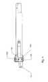
- FIG. 1is a perspective view of a transceiver module with a release mechanism according to the present invention installed in a cage assembly.
- FIG. 2is a perspective view of the transceiver module removed from the cage assembly, and with the bail and handle in their locked positions.
- FIG. 3is a perspective view of the transceiver module with the bail and handle in their released positions.
- FIG. 4is a side view of the transceiver module with the bail and handle in their released positions.
- the present inventionis a fiber optic connector release mechanism as illustrated in FIGS. 1-4 .
- the release mechanismis used on a transceiver module 10 housed in a cage assembly 12 that is typically permanently mounted on a printed circuit board.
- the release mechanismcomprises a sliding handle 14 operated by a cam mounted bail 16 .
- the transceiver module 10is held in place in the cage 12 by a pair of locking tabs 121 protruding inward from the sides of the cage 12 .
- the locking tabs 121are received in slide paths 101 formed in sides of the transceiver module housing 102 .
- a flat segment 103 of the transceiver module housing 102depresses the locking tabs 121 .
- the locking tabs 121rebound into the slide paths 101 on each side of the module housing 103 , where they abut shoulders 104 at the ends of the slide paths 101 .
- the transceiver module 10therefore cannot be removed from the cage assembly 12 with the locking tabs 121 in place.
- the handle 14is mounted on the module housing 103 by means of extended arms 141 that are received in the slide paths 101 .
- the handle 14is positioned behind abutments 105 above a pair of LC plug bays 106 .
- the abutments 105define the forward limitation of the slide of the handle 14 relative to the module housing 103 .
- wedge elements 142that each include an angled or arced surface 1421 that allows the wedge elements 142 to raise the locking tabs 121 when the release mechanism is actuated.
- the locking tabs 121rest on plateau sections 1422 of the wedge elements after the locking tabs 121 have been pressed outward.
- the actuating device of the release mechanismis the bail 16 .
- the bail 16is mounted on the handle 14 by a first axis pin 161 received in an eccentric cam slot 143 in the handle 14 and a second axis pin 162 received in a straight second slot 144 .
- the top side of the bail 16includes a conveniently shaped finger plate 163 that provides a means for a user to easily grasp the bail 16 .
- Tabs 165that extend from a rear portion of the bail 16 define slots 164 that receive tapered bosses 145 of the handle 14 so as to secure the bail 16 when it is in the locked position shown in FIGS. 1 and 2 .
- the dual rotational axes of the bail 16provides the bail 16 with a two stage travel path.
- the first axis pin 161moves through a first stage 1431 of the cam slot 143 as the bail rotates through an arc of approximately 45°. It should be noted that the bail 16 cannot complete this first arc unless the LC plugs have been removed from the plug bays 106 of the transceiver module 10 .
- This featureprovides a failsafe method for assuring that the transceiver module 10 cannot be removed from the cage assembly 12 while the LC plugs are in position, thereby avoiding inadvertent data transmission interruption.
Landscapes
- Physics & Mathematics (AREA)
- General Physics & Mathematics (AREA)
- Optics & Photonics (AREA)
- Optical Couplings Of Light Guides (AREA)
- Details Of Connecting Devices For Male And Female Coupling (AREA)
Abstract
Description
Claims (12)
Priority Applications (1)
| Application Number | Priority Date | Filing Date | Title |
|---|---|---|---|
| US10/454,643US6872010B1 (en) | 2003-06-03 | 2003-06-03 | Fiber optic connector release mechanism |
Applications Claiming Priority (1)
| Application Number | Priority Date | Filing Date | Title |
|---|---|---|---|
| US10/454,643US6872010B1 (en) | 2003-06-03 | 2003-06-03 | Fiber optic connector release mechanism |
Publications (1)
| Publication Number | Publication Date |
|---|---|
| US6872010B1true US6872010B1 (en) | 2005-03-29 |
Family
ID=34312130
Family Applications (1)
| Application Number | Title | Priority Date | Filing Date |
|---|---|---|---|
| US10/454,643Expired - LifetimeUS6872010B1 (en) | 2003-06-03 | 2003-06-03 | Fiber optic connector release mechanism |
Country Status (1)
| Country | Link |
|---|---|
| US (1) | US6872010B1 (en) |
Cited By (28)
| Publication number | Priority date | Publication date | Assignee | Title |
|---|---|---|---|---|
| US20060056773A1 (en)* | 2004-09-14 | 2006-03-16 | Rui-Shen Tsai | Optical transceiver module |
| US20060215968A1 (en)* | 2004-02-20 | 2006-09-28 | Andrew Kayner | Transceiver module |
| EP1708311A1 (en)* | 2005-03-29 | 2006-10-04 | Fourte Design & Development | Fiber optic connector release mechanism |
| US20070149028A1 (en)* | 2005-12-28 | 2007-06-28 | Hitachi Cable, Ltd. | Latching mechanism and electronic module having same |
| US20080089649A1 (en)* | 2006-10-11 | 2008-04-17 | Dong-Yang Wang | Fiber optic connector release mechanism |
| US20080138016A1 (en)* | 2006-12-12 | 2008-06-12 | Japan Aviation Electronics Industry, Limited | Optical connector excellent in maintenance of a connected state |
| US20090092399A1 (en)* | 2007-10-05 | 2009-04-09 | Finisar Corporation | Monolithic shell for an optical electrical device |
| US20090123157A1 (en)* | 2007-10-08 | 2009-05-14 | Finisar Corporation | Printed circuit board assembly carrier for an optical electrical device |
| US20090215924A1 (en)* | 2008-02-26 | 2009-08-27 | Momentive Performance Materials Inc. | Silicone rubber exhibiting effective antimicrobial activity |
| US20090244856A1 (en)* | 2008-03-27 | 2009-10-01 | Methode Electronics, Inc. | Retracting lock mechanism for an electronics device |
| US7841779B1 (en)* | 2007-09-07 | 2010-11-30 | Fourte Design & Development, Llc | Fiber optic module release mechanism |
| CN102122036A (en)* | 2010-01-08 | 2011-07-13 | 株式会社藤仓 | Optical transceiver module and method of manufacturing the optical transceiver module |
| CN101669054B (en)* | 2007-04-23 | 2012-01-11 | 住友电气工业株式会社 | Optical fiber connector and optical cable |
| US20120106902A1 (en)* | 2010-11-02 | 2012-05-03 | Raja Maruthu Thirugnanam | Fiber optic transceiver module release mechanism |
| US20120106903A1 (en)* | 2010-11-02 | 2012-05-03 | Fourte Design & Development, Llc. | Fiber Optic Transceiver Module Release Mechanism |
| US20120302078A1 (en)* | 2011-05-26 | 2012-11-29 | All Best Electronics Co., Ltd. | Pull-out structure for connector |
| US8465215B1 (en) | 2010-12-29 | 2013-06-18 | Huawei Technologies Co., Ltd. | Pluggable apparatus |
| KR20140006988A (en)* | 2011-04-28 | 2014-01-16 | 피니사 코포레이숀 | Latching mechanisms for pluggable electronic devices |
| US9028155B2 (en) | 2012-05-31 | 2015-05-12 | Source Photonics, Inc. | Latchable module housings and methods of making and using the same |
| US9182558B2 (en)* | 2012-11-30 | 2015-11-10 | Delta Electronics, Inc. | Communication module |
| US20160004022A1 (en)* | 2013-02-05 | 2016-01-07 | Sumitomo Electric Industries, Ltd. | Pluggable optical transceiver having pull-pull-tab |
| US9377591B1 (en)* | 2015-02-06 | 2016-06-28 | Delta Electronics, Inc. | Fiber-optic communication module with de-latching mechanism |
| US9523828B2 (en) | 2013-08-01 | 2016-12-20 | Sumitomo Electric Industries, Ltd. | Optical transceiver having bail working independently of linear motion of slider |
| CN105164560B (en)* | 2013-03-05 | 2017-03-22 | 菲尼萨公司 | Latch mechanism for communication module |
| US20180129000A1 (en)* | 2016-11-07 | 2018-05-10 | Tyco Electronics (Shanghai) Co. Ltd. | Connector |
| CN109031546A (en)* | 2018-08-16 | 2018-12-18 | 河北华美光电子有限公司 | The tripper of pluggable optical module and its pluggable optical module of application |
| WO2022068943A1 (en)* | 2021-03-26 | 2022-04-07 | 青岛海尔空调器有限总公司 | Air conditioner |
| US12044890B2 (en) | 2019-12-31 | 2024-07-23 | Huawei Technologies Co., Ltd. | Optical module unlocking apparatus, optical module, and optical communications device |
Citations (4)
| Publication number | Priority date | Publication date | Assignee | Title |
|---|---|---|---|---|
| US20030108300A1 (en)* | 2001-12-06 | 2003-06-12 | Walker Harold Y. | Method and system for releasing a pluggable module |
| US20040033027A1 (en)* | 2001-04-14 | 2004-02-19 | Pang Ron Cheng Chuan | Cam-follower release mechanism for fiber optic modules with side delatching mechanisms |
| US6746158B2 (en)* | 2002-01-31 | 2004-06-08 | Agilent Technologies, Inc. | Pull detach mechanism for fiber optic transceiver module |
| US6789958B2 (en)* | 2001-08-31 | 2004-09-14 | Infineon Technologies Ag | Release mechanism for pluggable fiber optic transceiver |
- 2003
- 2003-06-03USUS10/454,643patent/US6872010B1/ennot_activeExpired - Lifetime
Patent Citations (4)
| Publication number | Priority date | Publication date | Assignee | Title |
|---|---|---|---|---|
| US20040033027A1 (en)* | 2001-04-14 | 2004-02-19 | Pang Ron Cheng Chuan | Cam-follower release mechanism for fiber optic modules with side delatching mechanisms |
| US6789958B2 (en)* | 2001-08-31 | 2004-09-14 | Infineon Technologies Ag | Release mechanism for pluggable fiber optic transceiver |
| US20030108300A1 (en)* | 2001-12-06 | 2003-06-12 | Walker Harold Y. | Method and system for releasing a pluggable module |
| US6746158B2 (en)* | 2002-01-31 | 2004-06-08 | Agilent Technologies, Inc. | Pull detach mechanism for fiber optic transceiver module |
Cited By (46)
| Publication number | Priority date | Publication date | Assignee | Title |
|---|---|---|---|---|
| US20060215968A1 (en)* | 2004-02-20 | 2006-09-28 | Andrew Kayner | Transceiver module |
| US7114857B1 (en)* | 2004-02-20 | 2006-10-03 | Picolight, Inc. | Transceiver module |
| US7303336B2 (en) | 2004-02-20 | 2007-12-04 | Jds Uniphase Corporation | Transceiver module |
| US20060056773A1 (en)* | 2004-09-14 | 2006-03-16 | Rui-Shen Tsai | Optical transceiver module |
| EP1708311A1 (en)* | 2005-03-29 | 2006-10-04 | Fourte Design & Development | Fiber optic connector release mechanism |
| EP1833125A1 (en)* | 2005-03-29 | 2007-09-12 | Fourte Design & Development | Fiber optic connector release mechanism |
| US20070149028A1 (en)* | 2005-12-28 | 2007-06-28 | Hitachi Cable, Ltd. | Latching mechanism and electronic module having same |
| US7306381B2 (en)* | 2005-12-28 | 2007-12-11 | Hitachi Cable, Ltd. | Latching mechanism and electronic module having same |
| US20080089649A1 (en)* | 2006-10-11 | 2008-04-17 | Dong-Yang Wang | Fiber optic connector release mechanism |
| US7513693B2 (en)* | 2006-10-11 | 2009-04-07 | Liverage Technology Inc. | Fiber optic connector release mechanism |
| US20080138016A1 (en)* | 2006-12-12 | 2008-06-12 | Japan Aviation Electronics Industry, Limited | Optical connector excellent in maintenance of a connected state |
| US7484898B2 (en)* | 2006-12-12 | 2009-02-03 | Japan Aviation Electronics Industry, Limited | Optical connector excellent in maintenance of a connected state |
| CN101669054B (en)* | 2007-04-23 | 2012-01-11 | 住友电气工业株式会社 | Optical fiber connector and optical cable |
| US7841779B1 (en)* | 2007-09-07 | 2010-11-30 | Fourte Design & Development, Llc | Fiber optic module release mechanism |
| US20090092399A1 (en)* | 2007-10-05 | 2009-04-09 | Finisar Corporation | Monolithic shell for an optical electrical device |
| WO2009046411A3 (en)* | 2007-10-05 | 2009-05-22 | Finisar Corp | Monolithic shell for an optical electrical device |
| US7802929B2 (en) | 2007-10-05 | 2010-09-28 | Finisar Corporation | Monolithic shell for an optical electrical device |
| US20090123157A1 (en)* | 2007-10-08 | 2009-05-14 | Finisar Corporation | Printed circuit board assembly carrier for an optical electrical device |
| US8202011B2 (en) | 2007-10-08 | 2012-06-19 | Finisar Corporation | Printed circuit board assembly carrier for an optical electrical device |
| US20090215924A1 (en)* | 2008-02-26 | 2009-08-27 | Momentive Performance Materials Inc. | Silicone rubber exhibiting effective antimicrobial activity |
| US8335088B2 (en) | 2008-03-27 | 2012-12-18 | Methode Electronics, Inc. | Lock mechanism for electronic device |
| US8040687B2 (en) | 2008-03-27 | 2011-10-18 | Methode Electronics, Inc. | Retracting lock mechanism for an electronics device |
| US20090244856A1 (en)* | 2008-03-27 | 2009-10-01 | Methode Electronics, Inc. | Retracting lock mechanism for an electronics device |
| US20110170832A1 (en)* | 2010-01-08 | 2011-07-14 | Fujikura Ltd. | Optical transceiver module and method of manufacturing the optical transceiver module |
| CN102122036A (en)* | 2010-01-08 | 2011-07-13 | 株式会社藤仓 | Optical transceiver module and method of manufacturing the optical transceiver module |
| US20120106902A1 (en)* | 2010-11-02 | 2012-05-03 | Raja Maruthu Thirugnanam | Fiber optic transceiver module release mechanism |
| US20120106903A1 (en)* | 2010-11-02 | 2012-05-03 | Fourte Design & Development, Llc. | Fiber Optic Transceiver Module Release Mechanism |
| US8206043B2 (en)* | 2010-11-02 | 2012-06-26 | Fourte Design & Development, Llc | Fiber optic transceiver module release mechanism |
| US8226305B2 (en)* | 2010-11-02 | 2012-07-24 | Fourte Design & Development, Llc. | Fiber optic transceiver module release mechanism |
| US8465215B1 (en) | 2010-12-29 | 2013-06-18 | Huawei Technologies Co., Ltd. | Pluggable apparatus |
| JP2014519141A (en)* | 2011-04-28 | 2014-08-07 | フィニサー コーポレイション | Latching mechanism for pluggable electronic devices |
| US9520662B2 (en) | 2011-04-28 | 2016-12-13 | Finisar Corporation | Latching mechanisms for pluggable electronic devices |
| KR20140006988A (en)* | 2011-04-28 | 2014-01-16 | 피니사 코포레이숀 | Latching mechanisms for pluggable electronic devices |
| US20120302078A1 (en)* | 2011-05-26 | 2012-11-29 | All Best Electronics Co., Ltd. | Pull-out structure for connector |
| US8388366B2 (en)* | 2011-05-26 | 2013-03-05 | All Best Electronics Co., Ltd. | Pull-out structure for connector |
| US9028155B2 (en) | 2012-05-31 | 2015-05-12 | Source Photonics, Inc. | Latchable module housings and methods of making and using the same |
| US9182558B2 (en)* | 2012-11-30 | 2015-11-10 | Delta Electronics, Inc. | Communication module |
| US9541719B2 (en)* | 2013-02-05 | 2017-01-10 | Sumitomo Electric Industries, Ltd. | Pluggable optical transceiver having pull-pull-tab |
| US20160004022A1 (en)* | 2013-02-05 | 2016-01-07 | Sumitomo Electric Industries, Ltd. | Pluggable optical transceiver having pull-pull-tab |
| CN105164560B (en)* | 2013-03-05 | 2017-03-22 | 菲尼萨公司 | Latch mechanism for communication module |
| US9523828B2 (en) | 2013-08-01 | 2016-12-20 | Sumitomo Electric Industries, Ltd. | Optical transceiver having bail working independently of linear motion of slider |
| US9377591B1 (en)* | 2015-02-06 | 2016-06-28 | Delta Electronics, Inc. | Fiber-optic communication module with de-latching mechanism |
| US20180129000A1 (en)* | 2016-11-07 | 2018-05-10 | Tyco Electronics (Shanghai) Co. Ltd. | Connector |
| CN109031546A (en)* | 2018-08-16 | 2018-12-18 | 河北华美光电子有限公司 | The tripper of pluggable optical module and its pluggable optical module of application |
| US12044890B2 (en) | 2019-12-31 | 2024-07-23 | Huawei Technologies Co., Ltd. | Optical module unlocking apparatus, optical module, and optical communications device |
| WO2022068943A1 (en)* | 2021-03-26 | 2022-04-07 | 青岛海尔空调器有限总公司 | Air conditioner |
Similar Documents
| Publication | Publication Date | Title |
|---|---|---|
| US6872010B1 (en) | Fiber optic connector release mechanism | |
| US8206043B2 (en) | Fiber optic transceiver module release mechanism | |
| US8226305B2 (en) | Fiber optic transceiver module release mechanism | |
| US7841779B1 (en) | Fiber optic module release mechanism | |
| US7347711B1 (en) | Fiber optic module release mechanism | |
| US9276358B2 (en) | Transceiver module release mechanism | |
| US7513693B2 (en) | Fiber optic connector release mechanism | |
| US6485192B1 (en) | Optical device having an integral array interface | |
| US6430053B1 (en) | Pluggable transceiver module having rotatable release and removal lever with living hinge | |
| JP5684429B2 (en) | Latching mechanism for pluggable electronic devices | |
| EP1771757B1 (en) | Modular optical device package | |
| US7307847B2 (en) | Pluggable video module | |
| US6776645B2 (en) | Latch and release system for a connector | |
| JP2007171980A (en) | Latch structure for pluggable transceiver | |
| US20100081303A1 (en) | High density pluggable electrical and optical connector | |
| US7347634B2 (en) | Opto-electrical module for optical signals from at least two optical data channels for arranging on a main circuit board of a component assembly and opto-electrical component assembly | |
| US20060078259A1 (en) | Latching mechanism for small form factor pluggable modules | |
| JP2015166762A (en) | Optical transceiver | |
| EP1708311B1 (en) | Fiber optic transceiver module secured in a cage and release mechanism | |
| US8571375B1 (en) | Release mechanism and transceiver module using the same | |
| EP1014131A2 (en) | Fiber optic tap connector displacing the cladding | |
| JP4708827B2 (en) | Optical fiber connector release mechanism | |
| US20090290881A1 (en) | Optical communication apparatus and optical transceiver thereof | |
| US20040067027A1 (en) | Optical device having an integral array interface | |
| CN212647087U (en) | Optical module |
Legal Events
| Date | Code | Title | Description |
|---|---|---|---|
| AS | Assignment | Owner name:FOURTE DESIGN & DEVELOPMENT, LLC, CALIFORNIA Free format text:ASSIGNMENT OF ASSIGNORS INTEREST;ASSIGNOR:BIANCHINI, GIONI;REEL/FRAME:014145/0415 Effective date:20030507 | |
| FPAY | Fee payment | Year of fee payment:4 | |
| REMI | Maintenance fee reminder mailed | ||
| FEPP | Fee payment procedure | Free format text:PETITION RELATED TO MAINTENANCE FEES GRANTED (ORIGINAL EVENT CODE: PMFG); ENTITY STATUS OF PATENT OWNER: SMALL ENTITY Free format text:PETITION RELATED TO MAINTENANCE FEES FILED (ORIGINAL EVENT CODE: PMFP); ENTITY STATUS OF PATENT OWNER: SMALL ENTITY | |
| LAPS | Lapse for failure to pay maintenance fees | ||
| REIN | Reinstatement after maintenance fee payment confirmed | ||
| FP | Lapsed due to failure to pay maintenance fee | Effective date:20130329 | |
| PRDP | Patent reinstated due to the acceptance of a late maintenance fee | Effective date:20130611 | |
| FPAY | Fee payment | Year of fee payment:8 | |
| STCF | Information on status: patent grant | Free format text:PATENTED CASE | |
| SULP | Surcharge for late payment | ||
| FPAY | Fee payment | Year of fee payment:12 | |
| AS | Assignment | Owner name:FOURTE INTERNATIONAL LTD, VIRGIN ISLANDS, BRITISH Free format text:ASSIGNMENT OF ASSIGNORS INTEREST;ASSIGNOR:FOURTE DESIGN & DEVELOPMENT, LLC;REEL/FRAME:041155/0679 Effective date:20161104 | |
| AS | Assignment | Owner name:FOURTE INTERNATIONAL LTD, VIRGIN ISLANDS, BRITISH Free format text:CORRECTIVE ASSIGNMENT TO CORRECT THE INCORRECT PATENT NO. 6764318 PREVIOUSLY RECORDED AT REEL: 041155 FRAME: 0679. ASSIGNOR(S) HEREBY CONFIRMS THE ASSIGNMENT;ASSIGNOR:FOURTE DESIGN & DEVELOPMENT, LLC;REEL/FRAME:042657/0001 Effective date:20161104 |