US6871116B2 - Determining pallet case configurations for placement by a robot - Google Patents
Determining pallet case configurations for placement by a robotDownload PDFInfo
- Publication number
- US6871116B2 US6871116B2US10/272,661US27266102AUS6871116B2US 6871116 B2US6871116 B2US 6871116B2US 27266102 AUS27266102 AUS 27266102AUS 6871116 B2US6871116 B2US 6871116B2
- Authority
- US
- United States
- Prior art keywords
- pallet
- cases
- layer
- case
- layers
- Prior art date
- Legal status (The legal status is an assumption and is not a legal conclusion. Google has not performed a legal analysis and makes no representation as to the accuracy of the status listed.)
- Expired - Lifetime, expires
Links
- 238000000034methodMethods0.000claimsabstractdescription64
- 239000000463materialSubstances0.000claimsabstractdescription44
- 239000000470constituentSubstances0.000claimsdescription13
- 230000000007visual effectEffects0.000description19
- 238000007726management methodMethods0.000description12
- 238000010586diagramMethods0.000description10
- 238000005259measurementMethods0.000description4
- 235000013361beverageNutrition0.000description3
- 238000004891communicationMethods0.000description3
- 238000004590computer programMethods0.000description3
- 238000013459approachMethods0.000description2
- 238000010276constructionMethods0.000description2
- 238000012545processingMethods0.000description2
- 230000015572biosynthetic processEffects0.000description1
- 239000011449brickSubstances0.000description1
- 238000004364calculation methodMethods0.000description1
- 238000006243chemical reactionMethods0.000description1
- 238000013461designMethods0.000description1
- 230000006870functionEffects0.000description1
- 230000010365information processingEffects0.000description1
- 230000000977initiatory effectEffects0.000description1
- 230000001788irregularEffects0.000description1
- 238000012544monitoring processMethods0.000description1
- 238000005457optimizationMethods0.000description1
- 230000001737promoting effectEffects0.000description1
- 238000012163sequencing techniqueMethods0.000description1
- 238000012546transferMethods0.000description1
Images


Classifications
- B—PERFORMING OPERATIONS; TRANSPORTING
- B07—SEPARATING SOLIDS FROM SOLIDS; SORTING
- B07C—POSTAL SORTING; SORTING INDIVIDUAL ARTICLES, OR BULK MATERIAL FIT TO BE SORTED PIECE-MEAL, e.g. BY PICKING
- B07C5/00—Sorting according to a characteristic or feature of the articles or material being sorted, e.g. by control effected by devices which detect or measure such characteristic or feature; Sorting by manually actuated devices, e.g. switches
- B07C5/04—Sorting according to size
- B07C5/10—Sorting according to size measured by light-responsive means
Definitions
- This inventionrelates to material handling systems and, more particularly, to building pallets using robotic systems.
- Material handling systemsare used in a wide variety of environments to receive, store, and load cases of goods for delivery to customers.
- material handling systemsinclude a data processor which can examine received customer orders to determine how many cases of customer selected product are to be included on a pallet for delivery to the customer.
- full layer gantries and palletizersare utilized to build pallets having full layers of cases.
- a full layer of casesrefers to a layer having a “footprint” or perimeter which approximates the perimeter of the pallet base, and thus, is substantially square or rectangular in shape.
- full layer gantriescan pull entire layers of cases from a supply pallet having a single product and transfer the entire layer to a pallet being built for delivery to a customer.
- the palletizercan form full layers of identical cases or cases that are substantially similar in height, width, and length, despite the fact that the cases are not identical in terms of content.
- the invention disclosed hereinprovides a solution for building pallets of cases within an automated material handling system. More particularly, those cases which cannot readily be added to a pallet as a full layer, for example by a palletizer or a full layer gantry, can be arranged and ordered for placement in a case by case fashion by a robot.
- One aspect of the present inventioncan include a method of determining pallet layers for placement by a material handling system robot. The method can include identifying cases for inclusion in a pallet and identifying case dimension information for the cases. Using the case dimension information, the cases can be classified into at least one group, wherein each group is defined by a height range such that cases classified within a group have a height within the height range associated with that group. The cases of one of the groups can be assigned to locations within a same pallet layer, wherein the pallet layer has an area within a predefined area range. The pallet can be built as specified by the assigned case locations using an automated material handling system configured with the robot.
- the methodfurther can include marking cases assigned to a pallet layer as being unavailable, and for cases that are not marked as available, performing the classifying step and the assigning step to form additional pallet layers.
- the assigning stepcan assign cases to each layer such that no column of more than a predetermined number of cases in height is formed in the pallet layers to be placed by the robot.
- the palletcan be built as specified by the assigned case locations using an automated material handling system configured with a robot.
- the pallet layerscan be configured such that an area of one of the layers is less than or equal to an area of another layer immediately beneath.
- Pallet layersalso can be configured such that the area of one of the pallet layers is greater than the area of another layer immediately beneath.
- Case splitscan be combined into a single virtual case for treatment as a single case for the classifying and assigning steps.
- the virtual casecan be formed of two smaller cases placed side by side or stacked vertically one on top of the other.
- the virtual case or casescan be identified after assigning the virtual case or cases to a location within a pallet.
- the virtual casescan be separated into constituent case splits. Cases of the groups also can be sorted according to height such that the assigning step assigns taller cases of a group to corner locations of the pallet layer.
- cases of each groupcan be compared with at least one pallet layer template specifying an arrangement of cases forming a pallet layer.
- the assigning stepcan include assigning cases of at least one of the groups to a same layer of the pallet according to a matched pallet layer template.
- the methodcan include comparing cases of at least one group with pallet layer templates designated for pallets having secured layers of cases.
- the palletcan be built as specified by the assigned case locations using an automated material handling system configured with the robot.
- the methodalso can include assigning cases of at least one of the groups to a different layer of the pallet according to a matched pallet layer template and orienting the different layer so that the orientation of the different layer is substantially perpendicular to the orientation of a layer beneath the different layer. Additionally, cases assigned to a pallet layer can be marked as unavailable. For cases which are available, the classifying step and the assigning step can be performed to form additional pallet layers wherein the assigning step assigns cases to each layer such that no column of more than a predetermined number of cases in height is formed in the pallet layers to be placed by the robot.
- the palletcan be built as specified by the assigned case locations using an automated material handling system configured with the robot.
- the layer determined in the assigning stepcan be limited to a perimeter which does not substantially exceed a perimeter of a pallet base.
- the perimeter of the layeralso can be less than the perimeter of the pallet base.
- the palletcan be built as specified by the assigned case locations using an automated material handling system configured with a robot.
- case splitscan be combined into one or more virtual cases for treatment as a single case for the comparing and assigning steps.
- the virtual case or casescan be identified after assigning the virtual case to a location within a pallet and separating the virtual case into constituent case splits.
- the spacing between each case of the layercan be adjusted to accommodate a robotic case grasping mechanism.
- cases of a groupcan be matched to a pallet layer template specifying a case arrangement for a higher number of cases before matching cases of the group to a pallet layer template specifying a case arrangement for a smaller number of cases. If the cases of a group match more than one pallet layer template, a pallet layer template specifying a largest number of cases can be selected.
- the methodfurther can include identifying at least one exception case within the list of cases, assigning the at least one exception case to an exception layer, and adding at least one of an additional exception case or a non-exception case to the exception layer as specified by an exception pallet layer template.
- Cases of the groupscan be sorted according to height. Accordingly, the assigning step can include assigning taller cases of a group to corner locations of the pallet layer. If cases of a group match more than one pallet layer template, a pallet layer template which produces a pallet layer having the largest area can be selected.
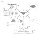
- FIG. 1is a schematic diagram illustrating an automated material handling system in accordance with the inventive arrangements disclosed herein.
- FIG. 2is a flow chart illustrating a method of determining pallet configuration data as performed by the robot control module of FIG. 1 .
- FIGS. 3 and 4are schematic diagrams illustrating visual representations of 6 case pallet layer templates for use with the present invention.
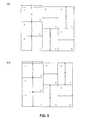
- FIG. 5is a schematic diagram illustrating visual representations of 7 case pallet layer templates for use with the present invention.
- FIGS. 6 , 7 , 8 , and 9are schematic diagrams illustrating visual representations of 8 case pallet layer templates for use with the present invention.
- FIG. 10is a schematic diagram illustrating visual representations of 9 case pallet layer templates for use with the present invention.
- the invention disclosed hereinprovides a solution for building pallets of cases within an automated material handling system.
- the present inventioncan determine an arrangement of cases to be added to a pallet in a case by case fashion. Those cases which cannot readily be added to a pallet as a full layer, for example by a palletizer or a full layer gantry, can be arranged and ordered for placement by a robot.
- the present inventioncan calculate case and pallet layer placement whether for adding cases and layers to empty pallet bases or pallet bases which will have been loaded with one or more layers of cases prior to being routed to the robot.
- FIG. 1is a schematic diagram illustrating an automated material handling system 100 having a control system 105 and a material handling system 110 .
- the control system 105can be configured to determine pallet configuration data specifying arrangements of cases for placement on one or more pallets. By determining pallet configuration data, the control system 105 provides direction to the material handling system 110 .
- the pallet configuration datacan specify the case release sequence and routing of pallets and cases throughout the material handling system 110 when the pallet is physically constructed. More particularly, the pallet configuration data can specify the order in which cases are to be released from various storage locations, which storage locations are to release cases, the routing of cases throughout the material handling system 110 , as well as the manner and order in which cases are to be added or placed onto pallets.
- the material handling system 110operating under direction of the control system 105 , can physically construct pallets as specified by the pallet configuration data.
- the material handling system 110can include programmable logic controllers 115 , which can be communicatively linked to the control system 105 via the communications network 120 , and material handling machinery 125 which is communicatively linked to the programmable logic controllers 115 .
- the material handling machinery 125can include one or more palletizers for adding layers of cases to pallets.
- the layerscan include cases of the same stock keeping unit (SKU) or cases of at least two different SKUs, but having substantially similar case measurements with respect to case length, width, weight, and height. Additionally, the palletizer can build pallet layers according to the geometry of cases to be included on the pallet.
- SKUstock keeping unit
- the palletizercan build pallet layers according to the geometry of cases to be included on the pallet.
- the material handling machinery 125can include a full layer gantry which can add full layers of cases of the same SKU to a pallet. Also, the material handling machinery 125 can include one or more robots which can add cases to a pallet individually.
- robotor “robotic system” as used herein, refers to a robotic case placement mechanism which is capable of placing a single case onto a pallet at a time. Although the present invention is not limited to a particular type of robot, one example is a robotic arm equipped with a case grasping mechanism.
- the various components of the material handling machinery 125can be fed cases either manually or by various case storage systems capable of providing full layers from pallets or providing individual cases. Regardless, the various components of the material handling machinery 125 can be interconnected via a conveyor system capable of selectively routing cases between each of the components of the material handling machinery 125 .
- the control system 105can include an order entry system 130 , an inventory management system 135 , a product release processor 140 , and a robot control module 145 , each being communicatively linked via the communications network 120 .
- the order entry system 130can have stored therein received or entered orders for cases of products to be delivered to customers.
- the orderscan specify the identity of products being ordered, the number of cases of product ordered, the identity of the customer, and the like.
- the inventory management system 135can include inventory management data specifying which cases are in stock and which cases are queued within the material handling system 110 for use in building a pallet.
- the inventory management system 135can specify case attributes such as the length, width, and height of cases, the weight of cases, and the load bearing capacity of cases.
- the product release processor 140can access orders from the order entry system 130 as well as inventory management data from the inventory management system 135 .
- the product release processor 140can determine pallet configuration data specifying full pallets or partial pallets of full layers. More particularly, the product release processor 140 can examine a customer order received or accessed from the order entry system 130 and, using the inventory management data, determine whether sufficient inventory exists to build one or more pallets in fulfillment of the customer order. From the customer orders and inventory management data, the product release processor 140 can identify any full layers which can be used in the construction of a pallet.
- the full layerscan include cases of a single SKU, meaning full layers of identical cases, or full layers of substantially similar cases.
- Full layers of substantially similar casescan include layers of cases of one or more different SKUs or different products which have similar if not identical case dimensions with respect to length, width, and height.
- the product release processor 140groups similar and identical cases for a given pallet. This grouping facilitates case routing throughout the material handling machinery 125 to the palletizer and the full layer gantry.
- the product release processor 140also determines pallet configuration data according to customers.
- the finished palletscan be unique to customer orders thereby enabling, for example, a driver to access all cases necessary to fulfill a particular customer order from one or more pallets in a single bay of a transport vehicle rather than accessing multiple truck bays to retrieve cases.
- the pallet configuration data determined by the product release processor 140specifies only full layers of cases. More particularly, the product release processor 140 determines which cases are to be placed on a given pallet.
- the product release processor 140also specifies locations of cases within the pallet to form full layers of cases. In consequence, not all of the pallets configured by the product release processor 140 are complete pallets.
- Unfinished pallet configuration datacan be provided to the robot control module 145 for completion. As the unfinished pallet configuration data specifies which cases, whether placed or not, are to be placed on a particular pallet, the robot control module 145 can determine locations for the remaining unplaced cases of a pallet.
- the robot control module 145can identify the cases to be included in a particular pallet.
- the pallet configuration dataalso specifies which cases already have been assigned a location within the pallet, that is which cases can be added to the pallet resulting in full layers using either the palletizer or the full layer gantry. Accordingly, the pallet configuration data also specifies which cases have yet to be assigned a location within the pallet.
- the robot control module 145can complete the pallet configuration data for a given pallet thereby assigning each unassigned case to a designated position or location within the pallet.
- the robot control module 145can classify the remaining cases into one or more groups according to case height. Cases belonging to a same group, and therefore having a similar height, can be used in the formation of a same pallet layer. The use of cases of similar height ensures that the resulting layer will provide a relatively flat surface for a next layer to be located atop of the newly determined layer, thereby promoting pallet stability.
- Acceptable case heights for each case groupcan be specified as a height range. Accordingly, a system administrator can set the height variation of a layer to control the amount of variation in height from one case of a group to the next, and therefore a layer. For instance, cases can be classified into groups wherein the maximum height deviation or range for cases within a single group does not exceed one inch, one-half inch, one-quarter inch, or the like. The height ranges associated with each group can be unique to that group.
- the robot control module 145can include one or more pallet layer templates 150 .
- the pallet layer templatesdefine patterns of allowable case sizes which can be arranged to form a full layer. Because case height is already accommodated by the grouping of cases, each pallet layer template specifies an arrangement of cases according to case length, case width, and case orientation.
- the pallet layer templatescan specify any of a variety of possible case arrangements which can accommodate any of a number of different case sizes depending upon the size of a pallet base and the dimensions of the cases to be placed onto the pallet base. For example, as shown, item 155 is a visual illustration of a pallet layer as specified by one of the pallet layer templates 150 .
- item 155depicts the top-down view, or the “footprint”, of a 7 case pallet layer arrangement.
- the pallet layerincludes 4 cases arranged in a cluster with 3 cases abutting the cluster.
- the orientation of the 3 abutting casesbeing substantially perpendicular to the orientation of the cluster of 4 cases.
- the product release processor 140can receive customer order information from the order entry system 130 and inventory management information from the inventory management system 135 .
- the product release processor 140can determine pallet configurations having full layers that can be built by the full layer gantry or the palletizer of the material handling machinery 125 . Notably, some pallet configurations may not include any layers which can be built by the full layer gantry or the palletizer, and therefore, must be entirely configured by the robot control module.
- the pallet configuration data 160can be provided to the robot control module 145 .
- the received pallet configuration data 160can specify full layers, if any, for the pallet currently being configured. Accordingly, the robot control module 145 can receive the pallet configuration data 160 , which also specifies those cases to be included within the current pallet, but which have yet to be assigned a location within the pallet.
- the robot control module 145using the pallet layer templates 150 , can assign locations to the unassigned cases within the pallet. Any cases leftover from the comparison of pallet layer templates with the unassigned cases, can be provided to a volume maximization module or plug-in which can assign cases to locations of the pallet and determine pallet configuration data for those cases.
- the pallet configuration data 160fully specifies the layers which have been configured for the pallet by the product release processor 140 including the case dimensions, the X, Y, and Z coordinates of cases within the pallet, and the orientation for the assigned cases. Accordingly, the robot control module 145 can determine the height and volume that the unfinished pallet, if built, would occupy. Notably, the dimensions of the pallet base can be included in the calculation as the pallet base dimensions are known quantities. The robot control module 145 can be programmed to assign the remaining unassigned cases to the pallet so as not to exceed a predetermined volume and/or height threshold. Accordingly, the robot control module 145 can calculate the available volume and height of a pallet for purposes of adding additional layers and cases to ensure that the resulting physical pallet is built according to particular height and/or volume requirements.
- the robot control module 145can augment the pallet configuration data 160 with the newly determined pallet configuration data, and publish the resulting complete pallet configuration data 165 .
- the complete pallet configuration data 165can be written to a data store such as a database, a table, or other memory which can be accessed by the product release processor 140 .
- the product release processorcan make the resulting pallet configuration data 165 available to the material handling system 105 so that the pallet can be built by the material handling machinery 125 in conformance with the finished pallet configuration data 165 .
- control system 105in particular the order entry system 130 , the inventory management system 135 , the product release processor 140 , and the robot control module 145 , are illustrated as separate application programs, it should be appreciated that the various components can be combined into one or more larger more complex application programs.
- the product release processor 140 and the robot control module 145can be combined into a single pallet configuration application program.
- Case arrangements for palletscan be determined one pallet at a time. Still, although the system of FIG. 1 is discussed with reference to completing pallet configuration data for a single pallet, it should be appreciated that pallet configuration data can specify pallet configurations for more than one pallet. For example, the pallet configuration data can specify pallet configurations for as many pallets as may be required to fulfill a particular customer order or to fulfill one or more customer orders for a given delivery route despite pallets being configured individually. Also, those skilled in the art will recognize that pallet configuration data can indirectly specify case dimensions. For example, case lists or pallet configuration data can specify case identifiers such as SKUs which can be used to cross reference and retrieve case dimension data from other systems such as the inventory management system. Accordingly, the pallet configuration data need not explicitly specify case dimensions.
- FIG. 2is a flow chart illustrating a method 200 of determining pallet configuration data for adding individual cases to a pallet as performed by the robot control module of FIG. 1 .
- the method 200is intended to process only those cases which have not yet been assigned a pallet location by the product release processor. Accordingly, the method can begin in step 205 , where a determination can be made as to whether one or more pallets are present which require sequencing.
- the robot control module and the product release processorcan be communicatively linked via a messaging system, a memory buffer, a shared memory, or another communications mechanism, through which the robot control module can determine whether pallet configuration data has been received or made available from the product release processor.
- step 210the method can proceed to step 210 . If not, the method can continue looping through step 205 to continue monitoring for the receipt or availability of pallet configuration data.
- the pallet configuration data for a selected and current palletcan be read into memory.
- virtual casescan be formed. For example, case splits specified within the pallet configuration data for the current pallet can be identified and combined into a virtual case.
- a case splitrefers to a smaller case which occupies approximately one-half of the volume of a single larger case of the same product type.
- An example of a case splitcan include a case of 12 beverage containers or a “12-pack” which can be combined with another 12-pack to approximate the dimensions of a larger case of 24 beverage containers.
- the smaller “12 pack” casescan be referred to as case splits.
- the case splitscan be combined into a single “virtual case”, at least for purposes of assigning the case splits to a location within the pallet being determined. Accordingly, once combined, the two case splits placed side by side are treated as a single larger case until the larger virtual case is again split into its constituent case splits.
- Virtual casesalso can be formed of two cases which can be placed one on top of the other to approximate the height of a taller case. Accordingly, within a layer of cases, one or more cases of the layer can be formed of two shorter cases, which when stacked, are substantially the same height as the other individual cases in the same pallet layer. More particularly, the height of the vertically stacked cases falls within the height range for cases in that layer. These vertically stacked cases also can be combined into a larger virtual case for purposes of assigning the cases to a location within the pallet being determined.
- the pallet configuration datacan be examined to identify any exception cases.
- Exception casescan be any case that does not fit one of the case layer templates or has an irregular size.
- the pallet configuration datacan indicate case dimensions and/or SKUs, exception cases can be identified using either identifier. For example, particular cases which are stocked and handled by the material handling system can be flagged as exception cases. If no exception cases are identified, the method can proceed to step 230 . If one or more exception cases are identified, however, the method can continue to step 225 where pallet layers can be configured which accommodate the exception cases.
- the robot control modulecan include one or more pallet layer templates specifically designed to accommodate exception cases.
- an exception layeras defined by an exception layer template, can be configured entirely of like or identical exception cases, or can be configured of exception cases in addition to other regular cases which are not designated as exception cases, but fit an exception pallet layer template.
- the exception layercan be configured with cases having heights within a predetermined range such that the exception pallet layer occupies at least a predetermined minimum area.
- the received pallet configuration datacan be examined to identify all combinations of at least a predetermined number of cases “n”. For example, all possible combinations of 6 or more cases which are within a predetermined height range of one another can be determined.
- the minimum number of cases for a group and a pallet layer templatecan vary according to the smallest number of cases that can be used to form a full pallet layer. In illustration, groups of cases having a height within one-half inch of one another can be placed in the same group.
- the limited height deviation from case to case within the groupfacilitates pallet stability. Still, as noted, the height deviation of cases within a group can be a user adjusted parameter.
- the groupscan be determined with reference to the virtual cases determined in step 215 and also by using the constituent cases of a virtual case.
- the virtual casecan be used within a taller group.
- Each constituent case of the virtual casealso can be used as part of another shorter group.
- two vertically stackable cases, each 8 inches tallcan form a virtual case which is 16 inches tall.
- the virtual casecan be counted as a single case for a group of cases having a height range of 16 inches to 16.5 inches.
- the same virtual casecan be counted as part of another group of cases having a height range of 15.5 inches to 16 inches.
- the two constituent caseseach having a height of 8 inches, can be included within a group of cases having a height range of 7.5 inches to 8 inches, and within another group of cases having a height range of 8 inches to 8.5 inches.
- casescan be listed in more than one group such that the robot control module can select a group with the most cases first. Accordingly, the maximum number of cases can be achieved for each group for purposes of forming a pallet layer.
- step 235a determination can be made as to whether any groups exist. That is, a determination can be made as to whether at least one group of “n” cases from the available unassigned cases of the pallet exists. If so, the method can proceed to step 240 . If not, however, the method can proceed to step 270 .
- the robot control modulecan begin a comparison of the groups with the available pallet layer templates to determine whether one or more pallet layers can be configured as specified by one or more of the predetermined pallet layer templates.
- the various groupscan be compared with the pallet layer templates.
- Each of the groupscan be compared with each of the templates to determine whether one or more pallet layers can be configured from the group according to the pallet layer templates. Any case arrangement matching a pallet layer template can be saved for further processing. For example, a group can be analyzed first to determine whether there are n+3 cases in the group, for example 9 cases. If so, the cases of the group are compared with the available 9 case pallet layer templates. If the available cases can be arranged to fit more than one 9 case pallet layer template, each possibility can be saved. Although the group being processed may include exactly 9 cases, the group can include more than 9 cases. For example, if the group includes 14 cases, the robot control module is programmed to begin matching permutations of the 14 cases against the 9 case pallet layer templates. As mentioned, any arrangement of 9 cases which matches a 9 case pallet layer template can be saved.
- the groupAfter comparison of a group with all 9 case pallet layer templates, the group can be checked as to whether it includes at least 8 cases. If so, the group can be compared with 8 case pallet layer templates and continue the comparing process down to the minimum number of cases specified for a template.
- the robot control modulecan begin comparing groups having the largest number of cases with templates which can accommodate the largest number of cases. After one group is processed additional groups can be compared to the pallet layer templates. Regardless of the order of the comparison of groups to pallet layer templates, each group can be compared with each pallet layer template.
- the area or footprint of the determined pallet layerscan be compared.
- the robot control modulecan be configured to reject any pallet layers which do not cover or have a footprint of at least a predetermined area.
- the area of a pallet layercan be determined either from the template used in configuring the pallet layer or from actual measurements of cases in the pallet layer.
- the minimum area requirementcan be at least a minimum percentage, such as 80 percent, of the area of the pallet base.
- step 270If none of the possible pallet layers meets this threshold, the method can proceed to step 270 . If one or more of the possible pallet layers meet the minimum area requirement, the method can proceed to step 255 . It should be appreciated, however, that the area check of step 250 can be performed when groups are compared with pallet layer templates such that any possible pallet layers which do not meet the minimum area requirement are not saved.
- the robot control modulecan select a pallet layer having the largest area.
- the area determinationcan be made with reference to the pallet layer template used to configure that pallet layer or can be performed dynamically using actual case measurements. Regardless, the robot control module can select the pallet layer having the largest area. Still, it should be appreciated that other preferences or weighting techniques can be utilized such as favoring particular templates due to the inherent stability of a pallet built using such a pallet layer case arrangement or a combination of both area and number of cases.
- any successful pallet layer configurationscan be written to memory.
- the cases used in the pallet layers configured by the robot control moduleare removed from memory or are otherwise rendered unavailable for successive pallet layer configurations to avoid mistakenly using the same case more than one time.
- the methodcan loop back to step 230 to reformulate the groups and begin comparing the newly formed groups with the pallet layer templates.
- the robot control modulecan maintain associations between constituent cases and virtual cases such that if a virtual case is used to construct a pallet layer, both constituent cases are removed from memory so as not to be included within the subsequently formed groups.
- the methodcan loop through steps 230 - 260 until no further pallet layers can be determined. Because cases and virtual cases can be included in more than one group for determining pallet layers, and then removed when assigned to a pallet layer prior to regrouping the cases, the robot control module can formulate stable and efficient pallet layers.
- the case splits for any determined layerscan be separated.
- any pallet layers determined in steps 240 - 255can be analyzed to identify virtual cases made from case splits in step 215 .
- the virtual cases which have been placed in pallet layers by the robot control modulethus far can be separated back into constituent case splits. Separating the virtual case back into constituent case splits ensures that when the pallet configuration data is provided to the material handling machinery, the robotic system will be aware that two smaller cases are to be placed rather than one larger case.
- the pallet layers which have been configured by the robot control modulecan be adjusted to accommodate the case grasping mechanism of the robot.
- the pallet layer templatesassume that cases will be placed immediately next to one another with minimal space, if any, disposed between each case. Such an arrangement, however, does not permit the case grasping mechanism of the robot to place cases on a pallet without making contact with previously placed cases. Contact between the robot and previously placed cases risks shifting cases thereby causing the resulting pallet to be misaligned. In consequence, the pallet layers must be reconfigured so that sufficient space exists between each case of a pallet layer to permit the placement of each case by the robot and case grasping mechanism. As the required distance between each case can vary according to the particular robot and case grasping mechanism used, the distance can be a configurable parameter. For purposes of discussion, however, the distance between each case of a pallet layer can be set to one-half inch.
- step 280a determination can be made as to whether any cases specified by the pallet configuration data remain to be processed or placed within the pallet. If so, the method can proceed to step 285 . If not, the method can proceed to step 265 .
- the robot control modulecan assign locations to the remaining cases. The robot control module can determine the pallet configuration information for the remaining cases which cannot be matched to available templates. The cases can be assigned to locations within the current pallet using any of a variety of third party plug-ins or algorithms which determine optimal case configurations. One such example is Cube IQ load optimization software available from MagicLogic Optimization Inc.
- step 290the non-layer case splits, that is any virtual cases that were assigned a location in step 285 can be separated into constituent case splits.
- step 293the cases which were assigned locations in step 285 can be reconfigured to accommodate for the robot and case grasping mechanism as discussed with reference to step 275 .
- the pallet configuration data determined throughout steps 270 - 296can be written to a data store as previously discussed.
- the cases that were assigned locations within the current pallet in step 285can be removed from memory.
- the cases of the pallet layerscan be resequenced for placement by the robot arm for proper reach. More particularly, as the placement of each case to be included within a pallet has been determined, the robot arm can be programmed to place each case on the pallet without colliding with previously placed cases, whether the cases were placed by the robot or another case loading mechanism.
- the entry point and exit point for the robot arm when placing casescan be determined. More particularly, the pallet configuration data specifies an X, Y, and Z coordinate specifying the location of each case within the pallet in addition to the orientation of the case. Accordingly, the X, Y, and Z points along the path of travel of the robot can be determined including any entry points and exit points. Notably, the entry point and exit point can be determined, at least in part, with reference to the coordinates of the present case being placed on the pallet.
- the robot armwhen entering and exiting the space to be occupied by cases of a pallet when placing a case, the robot arm can be programmed to rise a predetermined height above the top of the case being placed prior to initiating any lateral movement.
- the case grasping mechanismalso can be programmed to suitably grasp each case.
- Each casecan be placed in the center of the pallet layer template location or segment to which the case has been assigned.
- particular pallet layer templatescan be favored or weighted more than others.
- a 7 case pallet layercan be favored as being more stable than other pallet layers.
- adjacent pallet layerswhether built from the same template or not, can be selectively rotated approximately 180 degrees to promote case interlock among pallet layers and to avoid the stacking of cases into columns which typically results in less case interlock and less pallet stability.
- the robot control modulecan be configured to place pallet layers such that a same pallet layer template, is not used for more than a predetermined number of pallet layers which are to be placed in sequence one on top of the other.
- layers of 6 casesthen layers of 7 cases be placed in sequence on a pallet, but layers of the same number of cases wherein a different case arrangement is specified can be assigned sequentially to a pallet.
- the tallest cases of a given group which are to be included within a pallet layercan be located at the corners of the pallet layer. Locating the cases having the largest height in comparison with other cases within the pallet layer in the corner positions promotes pallet stability. Specifically, the cases of the next pallet layer, that is the pallet layer to be placed atop of the current pallet layer, are more likely to lean in towards one another rather than lean outward. In consequence, the pallet is less susceptible to collapse.
- the robot control modulealso can be configured to optionally place a final pallet layer of cases which do not conform to a given height requirement. That is, a layer of cases having disparate heights which need not fall within the defined height tolerance for a group, can be placed.
- the casescan be placed according to a template or can be placed such that the cases occupy a minimum area without reference to a template. If no template is used, additional constraints can be applied such as ensuring that the perimeter of the layer falls within a predetermined range.
- each case of the final layercan be regarded as an independent zone which can be provided to the third party plug-in.
- the final layerwould provide a number of individual platforms for receiving additional cases that is equal to the number of cases in the layer rather than serving as a single platform the size of the entire layer.
- each of the 7 casescan be regarded as an individual space for receiving additional cases.
- such a configurationcan be optional in that the feature can be inactivated or can be selectively activated, for example in cases wherein the number of cases left to be placed on a pallet does not exceed a predetermined maximum number of cases.
- FIG. 3is a schematic diagram illustrating visual representations 300 and 310 of two different 6 pallet layer templates.
- the visual representations 300 and 310illustrate the overhead view or footprint of the pallet layer. As shown, visual representation 300 occupies a larger area than visual representation 310 .
- the pallet layer template having the largest areacan be used or preferred in cases wherein the robot is to place pallet layers on a fresh pallet, that is a pallet base not having any existing layers. Although the dimensions can be varied for differently sized pallets, the templates disclosed herein can be suitable for placing beverage containers on 40 inch by 32 inch pallets.
- the pallet layer template represented by view 310can be selected in situations where the robot is to place layers onto a pallet already having layers which were placed by either the full layer gantry or the palletizer.
- pallets already having layerscan be provided to a securing station such as a stretch-wrapper.
- a securing stationsuch as a stretch-wrapper.
- casestypically are cinched together such that the area of a pallet layer becomes less than had the pallet not been secured.
- the pallet layer template represented by view 310can be used when a pallet already has one or more layers of cases which have been secured, and therefore, has less of a stackable area or surface available upon which a next pallet layer can be build and/or placed.
- the pallet layer templates illustrated by views 410 , 510 , 610 , 710 , 810 , 910 , and 1010can be used when a pallet has secured layers already placed.
- the cases of a given groupthat is cases having a height within a predetermined range of one another, are compared in terms of length and width with the individual locations of the pallet layer templates. More particularly, each case assigned to a location of a pallet layer template must fit within the length and width dimensions specified for that location of the pallet layer template. A case must not exceed the specified length and width of the location in the pallet layer template to which the case was assigned.
- the length and width of a casecan be smaller than the specified dimensions of the location in the pallet layer template to which the case was assigned. If so, the case can be positioned in the center of its assigned pallet layer template location. For example, if the length and/or width of a case is less than the specified length and/or width for its assigned location in the pallet layer template, space may exist between that case and other cases of the same pallet layer. As more than one case of a pallet layer may be smaller than the dimensions of their assigned pallet layer template locations, space can exist between one or more cases of the same pallet layer.
- the minimum area requirementwhich can be calculated using actual measurements of cases assigned to a pallet layer, can ensure that the pallet layer occupies a minimum area, and therefore, provides a stable base or foundation upon which additional pallet layers can be placed and/or built.
- the robot control modulecan sort the cases of each group according to height.
- the numbers located in the upper left-hand corner of the cases of the visual representations 300 and 310indicate relative heights of the cases to be placed within a similarly configured pallet layer. For example a “ 1 ” in the upper left hand corner indicates that the case in that position of the layer is to be the tallest case, or the case having the greatest height, of all the other cases within that pallet layer. A “ 2 ” indicates that the case is the second tallest, and so on.
- the cases having the largest heightcan be located in the corners of the pallet layer.
- the four corner cases of a pallet layercan be the tallest cases of the pallet layer and need not be positioned in a particular corner as illustrated in FIG. 3 .
- the number located in the lower right hand corner of the casesindicates the order in which the case is to be physically placed in the pallet layer by the robot.
- the pallet layer case placement orderfacilitates the placement of cases which are farthest from the robot arm first. Still, although each individual pallet layer template specifies the order in which cases are to be placed by the robot, it should be appreciated that a given pallet layer need not be completely placed by the robot before the robot begins placing cases from another layer above. This enables the robot to build the pallet beginning in the locations farthest from the robot as well as build distant portions of the pallet in height prior to placing cases closer to the robot so as to avoid collisions with placed cases.
- FIGS. 4 and 5are schematic diagrams, each illustrating visual representations of two 7 case pallet layer templates.
- FIG. 4shows visual representations 400 and 410 and
- FIG. 5depicts visual representations 500 and 510 .
- each casewhen determining whether cases of a group match a given pallet layer template, each case must be sized to fit completely within a location of the pallet layer template. If, for example, a group of cases can fit both templates 400 and 410 , then the template which utilizes the most volume, as computed according to actual case dimensions, is selected.
- FIGS. 6 , 7 , 8 , and 9are schematic diagrams, each illustrating visual representations of two different 8 case pallet layer templates.
- FIG. 6depicts visual representations 600 and 610 and
- FIG. 7shows visual representations 700 and 710 .
- FIG. 8depicts visual representations 800 and 810 and
- FIG. 9shows visual representations 900 and 910 .
- FIG. 10is a schematic diagram illustrating visual representations 1000 and 1010 of two different 9 case pallet layer templates.
- Yet another embodiment of the present inventioncan include determining pallet layers without using templates.
- casescan be classified into groups based upon height as discussed.
- pallet layerscan be configured using cases of the same group with reference to a maximum and minimum area which must be filled. Additional constraints with regard to the perimeter not being substantially less than or greater than the pallet base or a previous layer also can be applied.
- such an embodimentcan assign cases to locations within a given layer.
- the robot control modulecan ensure that cases interlock such that columns are avoided. For example, rules can be followed which would prohibit a layer from being formed which allows a column of more than a predetermined number of cases to exist.
- each layerneed not completely interlock, although such a goal can be achieved.
- stable pallet layerscan be achieved.
- pallet layerscan be built with substantially straight and vertical edges, this embodiment also can configure a pallet in a pyramid fashion.
- the present inventioncan be realized in hardware, software, or a combination of hardware and software.
- the present inventioncan be realized in a centralized fashion in one computer system, or in a distributed fashion where different elements are spread across several interconnected computer systems. Any kind of computer system or other apparatus adapted for carrying out the methods described herein is suited.
- a typical combination of hardware and softwarecan be a general purpose computer system with a computer program that, when being loaded and executed, controls the computer system such that it carries out the methods described herein.
- the present inventionalso can be embedded in a computer program product, which comprises all the features enabling the implementation of the methods described herein, and which when loaded in a computer system is able to carry out these methods.
- Computer program in the present contextmeans any expression, in any language, code or notation, of a set of instructions intended to cause a system having an information processing capability to perform a particular function either directly or after either or both of the following: a) conversion to another language, code or notation; b) reproduction in a different material form.
Landscapes
- Stacking Of Articles And Auxiliary Devices (AREA)
- Manipulator (AREA)
Abstract
Description
Claims (27)
Priority Applications (2)
| Application Number | Priority Date | Filing Date | Title |
|---|---|---|---|
| US10/272,661US6871116B2 (en) | 2002-10-17 | 2002-10-17 | Determining pallet case configurations for placement by a robot |
| US11/040,682US7221998B2 (en) | 2002-10-17 | 2005-01-21 | Determining pallet case configurations for placement by a robot |
Applications Claiming Priority (1)
| Application Number | Priority Date | Filing Date | Title |
|---|---|---|---|
| US10/272,661US6871116B2 (en) | 2002-10-17 | 2002-10-17 | Determining pallet case configurations for placement by a robot |
Related Child Applications (1)
| Application Number | Title | Priority Date | Filing Date |
|---|---|---|---|
| US11/040,682DivisionUS7221998B2 (en) | 2002-10-17 | 2005-01-21 | Determining pallet case configurations for placement by a robot |
Publications (2)
| Publication Number | Publication Date |
|---|---|
| US20040074823A1 US20040074823A1 (en) | 2004-04-22 |
| US6871116B2true US6871116B2 (en) | 2005-03-22 |
Family
ID=32092634
Family Applications (2)
| Application Number | Title | Priority Date | Filing Date |
|---|---|---|---|
| US10/272,661Expired - LifetimeUS6871116B2 (en) | 2002-10-17 | 2002-10-17 | Determining pallet case configurations for placement by a robot |
| US11/040,682Expired - Fee RelatedUS7221998B2 (en) | 2002-10-17 | 2005-01-21 | Determining pallet case configurations for placement by a robot |
Family Applications After (1)
| Application Number | Title | Priority Date | Filing Date |
|---|---|---|---|
| US11/040,682Expired - Fee RelatedUS7221998B2 (en) | 2002-10-17 | 2005-01-21 | Determining pallet case configurations for placement by a robot |
Country Status (1)
| Country | Link |
|---|---|
| US (2) | US6871116B2 (en) |
Cited By (13)
| Publication number | Priority date | Publication date | Assignee | Title |
|---|---|---|---|---|
| US20030176944A1 (en)* | 2002-03-13 | 2003-09-18 | Stingel Frederick J. | Automated container storage and delivery system |
| US20050125101A1 (en)* | 2002-10-17 | 2005-06-09 | Vertique, Inc. | Determining pallet case configurations for placement by a robot |
| US20050166552A1 (en)* | 2003-12-23 | 2005-08-04 | Omo Davide D. | Unit for packaging and palletizing rolls of toilet paper and/or kitchen towel |
| US20050246046A1 (en)* | 2004-04-29 | 2005-11-03 | International Business Machines Corporation | Method, system, and storage medium for facilitating a transport scheme in an automated material handling system environment |
| US20070005181A1 (en)* | 2002-03-13 | 2007-01-04 | Stingel Frederick J Iii | Automated container storage and delivery system |
| US20070078621A1 (en)* | 2005-09-30 | 2007-04-05 | Caterpillar Inc. | System for evaluating a parts carrier |
| US20070090956A1 (en)* | 2005-09-30 | 2007-04-26 | Daniel Deganis | Palletizing process for optimization of store aisle placement |
| US7266422B1 (en)* | 2004-04-09 | 2007-09-04 | Fanuc Robotics America, Inc. | Automated palletizing cases having mixed sizes and shapes |
| US7621108B1 (en) | 2008-07-18 | 2009-11-24 | The Procter & Gamble Company | Assembling a packaged bundle using an adjustable multi-shelved product transporter |
| US20100158647A1 (en)* | 2008-12-19 | 2010-06-24 | Lafontaine Daniel R | Automated order sequencing method and system |
| WO2013059366A2 (en) | 2011-10-17 | 2013-04-25 | Symbotic Llc | Pallet building system |
| CN107521986A (en)* | 2011-10-17 | 2017-12-29 | 西姆伯蒂克有限责任公司 | Pallet builds system |
| US10346987B1 (en)* | 2017-12-29 | 2019-07-09 | Datalogic Usa, Inc. | Locating objects on surfaces |
Families Citing this family (33)
| Publication number | Priority date | Publication date | Assignee | Title |
|---|---|---|---|---|
| US8000837B2 (en) | 2004-10-05 | 2011-08-16 | J&L Group International, Llc | Programmable load forming system, components thereof, and methods of use |
| JP4955666B2 (en)* | 2006-05-15 | 2012-06-20 | 平田機工株式会社 | Ceiling transfer storage system |
| US8406917B2 (en)* | 2006-08-16 | 2013-03-26 | Salahuddin F. Khan | System and method for random mixed palletizing of products |
| DE102007001263B4 (en)* | 2007-01-08 | 2015-07-23 | Kuka Roboter Gmbh | Robot system for loading load carriers with piece goods units |
| US20100150689A1 (en)* | 2007-02-16 | 2010-06-17 | Berry Paul A | Method and system for assembling pallets for stock orders |
| US8019465B2 (en)* | 2007-07-31 | 2011-09-13 | Align Technology, Inc. | System and methods for increasing efficiency in rapid prototyping processes |
| US8554371B2 (en)* | 2007-10-01 | 2013-10-08 | Kaufman Engineered Systems | Vision aided case/bulk palletizer system |
| DE102009003564A1 (en)* | 2009-03-04 | 2010-09-09 | Krones Ag | System, method and operating unit for creating mixed layers for pallets |
| US9321591B2 (en) | 2009-04-10 | 2016-04-26 | Symbotic, LLC | Autonomous transports for storage and retrieval systems |
| TWI680928B (en) | 2009-04-10 | 2020-01-01 | 美商辛波提克有限責任公司 | Vertical lift system and method for transferring uncontained case unit to and from a multilevel storage structure |
| DE102009056639A1 (en)* | 2009-12-02 | 2011-06-09 | Kuka Roboter Gmbh | Method and device for automated picking of containers |
| EP2362180B1 (en)* | 2010-02-05 | 2016-01-27 | Poly-clip System GmbH & Co. KG | Method for measuring a storage frame |
| US9561905B2 (en) | 2010-12-15 | 2017-02-07 | Symbotic, LLC | Autonomous transport vehicle |
| US9499338B2 (en) | 2010-12-15 | 2016-11-22 | Symbotic, LLC | Automated bot transfer arm drive system |
| US8965619B2 (en) | 2010-12-15 | 2015-02-24 | Symbotic, LLC | Bot having high speed stability |
| US8696010B2 (en) | 2010-12-15 | 2014-04-15 | Symbotic, LLC | Suspension system for autonomous transports |
| US11078017B2 (en) | 2010-12-15 | 2021-08-03 | Symbotic Llc | Automated bot with transfer arm |
| US9187244B2 (en) | 2010-12-15 | 2015-11-17 | Symbotic, LLC | BOT payload alignment and sensing |
| US9604258B2 (en)* | 2012-02-03 | 2017-03-28 | Span Tech Llc | Sortation systems and related methods |
| CN105705441B (en) | 2013-09-13 | 2018-04-10 | 西姆伯蒂克有限责任公司 | Autonomous transport car, the method for storing and fetching system and selection face being transmitted in the system |
| JP6469061B2 (en)* | 2016-09-29 | 2019-02-13 | ファナック株式会社 | Stacking pattern calculation device and stacking system |
| CA3051451A1 (en)* | 2017-01-26 | 2018-08-02 | Premier Tech Technologies Ltee | Robotic palletizing system and method |
| CN107263465A (en)* | 2017-05-02 | 2017-10-20 | 深圳市睿科智联科技有限公司 | A kind of cooperation robot recognition methods fed back based on end and system |
| US11440195B2 (en)* | 2018-07-25 | 2022-09-13 | Target Brands, Inc. | Autonomous cargo loading systems and methods |
| US10679379B1 (en) | 2019-05-31 | 2020-06-09 | Mujin, Inc. | Robotic system with dynamic packing mechanism |
| US10696494B1 (en) | 2019-05-31 | 2020-06-30 | Mujin, Inc. | Robotic system for processing packages arriving out of sequence |
| US11077554B2 (en) | 2019-05-31 | 2021-08-03 | Mujin, Inc. | Controller and control method for robotic system |
| US10647528B1 (en) | 2019-05-31 | 2020-05-12 | Mujin, Inc. | Robotic system for palletizing packages using real-time placement simulation |
| US10696493B1 (en)* | 2019-05-31 | 2020-06-30 | Mujin, Inc. | Robotic system with packing mechanism |
| JP7633184B2 (en)* | 2020-01-14 | 2025-02-19 | 株式会社Fuji | Parts supply unit storage and retrieval system |
| US11518573B2 (en)* | 2020-02-14 | 2022-12-06 | Dell Products L.P. | Palletizing containers for charging electronic devices contained therein |
| CN114021826B (en) | 2020-06-01 | 2025-02-07 | 梅卡曼德(北京)机器人科技有限公司 | Pallet space modeling planning method, device, and electronic equipment |
| CN114529155A (en)* | 2022-01-17 | 2022-05-24 | 湖南视比特机器人有限公司 | Method and system for dynamically stacking and framing workpieces |
Citations (15)
| Publication number | Priority date | Publication date | Assignee | Title |
|---|---|---|---|---|
| US4638171A (en)* | 1983-03-25 | 1987-01-20 | L'oreal | Method and device for the detection of the position of objects stacked on pallets |
| US4746255A (en)* | 1985-06-19 | 1988-05-24 | Graziano Roccabianca | Machine for automatically loading pallets |
| US4941374A (en)* | 1987-06-25 | 1990-07-17 | Focke & Co. (Gmbh & Co.) | Process and apparatus for the loading of pallets in layers |
| US5269645A (en)* | 1986-07-23 | 1993-12-14 | Kinetic Robotics Inc. | Material loads and methods for handling material |
| US5299691A (en)* | 1986-07-23 | 1994-04-05 | Kinetic Robotics, Inc. | Spacing sheet for handling material |
| US5310396A (en)* | 1990-04-09 | 1994-05-10 | Yamazaki Mazak Corporation | Flexible manufacturing system |
| US5372472A (en)* | 1991-02-11 | 1994-12-13 | Kinetic Robotics Inc. | Palletizer and palletizing methods |
| US5501571A (en)* | 1993-01-21 | 1996-03-26 | International Business Machines Corporation | Automated palletizing system |
| US5934864A (en)* | 1992-10-07 | 1999-08-10 | Hk Systems, Inc. | Case picking system |
| US6003917A (en)* | 1996-07-11 | 1999-12-21 | Tygard Machine And Manufacturing Co. | Clamping apparatus |
| US6201203B1 (en)* | 1999-05-12 | 2001-03-13 | Northrop Grumman Corporation | Robotic containerization system |
| US20030149644A1 (en)* | 2002-02-05 | 2003-08-07 | Vertique, Inc. | Method, system, and apparatus for delivering product |
| US20030176943A1 (en)* | 2002-03-13 | 2003-09-18 | Stingel Frederick J. | Automated container storage and delivery system |
| US6688839B1 (en)* | 1998-04-23 | 2004-02-10 | Certus Maschinenbau Gmbh | Device for processing bottles |
| US20040220694A1 (en)* | 2002-03-13 | 2004-11-04 | Stingel Frederick J. | Automated container storage and delivery system |
Family Cites Families (104)
| Publication number | Priority date | Publication date | Assignee | Title |
|---|---|---|---|---|
| GB210790A (en) | 1923-02-01 | 1924-06-05 | F I A T Societa Anonima | Improvements relating to engine cylinders |
| US2715950A (en)* | 1950-11-06 | 1955-08-23 | Comm Engineering Pty Ltd | Article dispensing systems |
| US3011621A (en) | 1960-06-21 | 1961-12-05 | Cutler Hammer Inc | Memory type order filling conveyor systems |
| US3153487A (en) | 1960-08-30 | 1964-10-20 | Cutler Hammer Inc | Storage conveyor system |
| US3262584A (en)* | 1964-05-25 | 1966-07-26 | Unarco Industries | Article distribution and storage system |
| US3436968A (en)* | 1965-02-11 | 1969-04-08 | Fairbanks Morse Inc | Processing control system |
| US3379321A (en)* | 1966-02-25 | 1968-04-23 | Fmc Corp | Carrier with an article label unit for a warehouse system |
| GB1187933A (en)* | 1967-06-24 | 1970-04-15 | Holstein & Kappert Maschf | Pallet Loading and Unloading Machines. |
| US3528213A (en)* | 1967-09-27 | 1970-09-15 | Lynch Corp | Conveying system |
| US3994407A (en)* | 1969-10-31 | 1976-11-30 | Litton Systems, Inc. | Can palletizer |
| US3643798A (en)* | 1970-02-27 | 1972-02-22 | Bell & Howell Co | Mail weighing and sorting machine |
| JPS5232133B1 (en)* | 1970-07-25 | 1977-08-19 | ||
| US3741345A (en)* | 1971-03-03 | 1973-06-26 | H Saridis | Semi automated retail store |
| US3757939A (en)* | 1971-05-12 | 1973-09-11 | Thompson & Co J | Method and apparatus for sorting articles such as letters |
| US3731782A (en)* | 1971-06-09 | 1973-05-08 | Hi Speed Checkweigher Co | Magnetic flow director |
| US3815313A (en)* | 1972-10-04 | 1974-06-11 | R Heisler | Apparatus and method for automatically sizing and wrapping a shrink wrap envelope around advancing luggage |
| IT1082516B (en)* | 1977-01-25 | 1985-05-21 | Bruno & Co Alisyncro | PLANT FOR THE DISTRIBUTION OF FOOD PRODUCTS PARTICULARLY SWEET TO A MULTIPLE OF PACKAGING STATIONS PLACED IN SERIES |
| US4161094A (en)* | 1977-03-16 | 1979-07-17 | Hauni-Werke Korber & Co. Kg. | Apparatus for processing biscuits or the like |
| CH625474A5 (en)* | 1978-02-14 | 1981-09-30 | Sig Schweiz Industrieges | |
| US4181947A (en)* | 1978-05-23 | 1980-01-01 | Rapistan, Incorporated | Conveyor sorting system |
| US4239434A (en) | 1979-04-09 | 1980-12-16 | The Boeing Company | Weight coded delivery conveyor system |
| US4385859A (en)* | 1979-09-25 | 1983-05-31 | Goossens Willy P M | Storage installation permitting the automatic selection and removal of articles |
| JPS57102277A (en) | 1980-12-19 | 1982-06-25 | Tokyo Shibaura Electric Co | Classifier with automatic extractor |
| DE3213119C2 (en)* | 1982-04-07 | 1995-10-05 | Knapp Logistik Automation | Method for picking piece goods and device for carrying out the method |
| US4627540A (en) | 1982-05-29 | 1986-12-09 | Tokyo Shibaura Denki Kabushiki Kaisha | Automatic mail processing apparatus |
| US4672553A (en)* | 1983-02-03 | 1987-06-09 | Goody Products, Inc. | Order processing method and apparatus |
| US4543970A (en)* | 1983-02-21 | 1985-10-01 | Tokyo Shibaura Denki Kabushiki Kaisha | Automatic set-up system |
| US4656591A (en)* | 1983-04-18 | 1987-04-07 | Goody Products, Inc. | Order processing method and apparatus (II) |
| US4567988A (en)* | 1983-04-22 | 1986-02-04 | Eastman Kodak Company | Apparatus and method for sorting and distributing objects |
| US4527937A (en)* | 1983-05-13 | 1985-07-09 | Orion Automation Industries | Automatic storage and distribution system |
| US4542808A (en)* | 1983-06-30 | 1985-09-24 | House Of Lloyd, Inc. | Order filling system |
| US4641271A (en)* | 1983-11-09 | 1987-02-03 | Hitachi, Ltd. | Piling planning method and piling system of cargoes by palletizing robot |
| US4692876A (en)* | 1984-10-12 | 1987-09-08 | Hitachi, Ltd. | Automatic freight stacking system |
| US4621745A (en) | 1984-10-24 | 1986-11-11 | Grace Robert W | Mechanized carton picker |
| DE3675446D1 (en) | 1985-07-16 | 1990-12-13 | Kao Corp | DEVICE FOR HANDLING GOODS. |
| US4826360A (en)* | 1986-03-10 | 1989-05-02 | Shimizu Construction Co., Ltd. | Transfer system in a clean room |
| US4786229A (en) | 1986-04-30 | 1988-11-22 | Henderson Thomas R | Document storage and retrieval apparatus and method |
| EP0244805B1 (en)* | 1986-05-09 | 1992-12-09 | Kao Corporation | Method of sorting goods and system therefor |
| US4988264A (en)* | 1986-07-23 | 1991-01-29 | Kinetic Robotics, Inc. | Apparatus for handling material |
| FR2610908B1 (en)* | 1987-02-18 | 1991-08-23 | Vega Automation Sa | METHOD AND DEVICE FOR STORING AND DISTRIBUTING CUT-OUT UNITS, ESPECIALLY FOR PACKAGING |
| US4815190A (en)* | 1987-08-20 | 1989-03-28 | Gmf Robotics Corporation | Method for automated assembly of assemblies such as automotive assemblies |
| US4894908A (en)* | 1987-08-20 | 1990-01-23 | Gmf Robotics Corporation | Method for automated assembly of assemblies such as automotive assemblies and system utilizing same |
| JPS6464759A (en)* | 1987-09-03 | 1989-03-10 | Hitachi Seiki Kk | Free-flow type production system |
| FR2620054B1 (en) | 1987-09-07 | 1990-02-16 | Maintenance Manutention Sarl | MEDIUM PARCEL SORTING DEVICE "POSTAL PACKAGE TYPE" |
| DE3731589A1 (en) | 1987-09-19 | 1989-03-30 | Fraunhofer Ges Forschung | METHOD AND DEVICE FOR DISTRIBUTING POSTAL GOODS |
| US4867628A (en)* | 1988-01-15 | 1989-09-19 | Ammon J Preston | Dispenser storage system |
| US5096367A (en)* | 1989-02-08 | 1992-03-17 | Kinetic Robotics Inc. | Processes for handling material |
| US4907699A (en)* | 1989-03-03 | 1990-03-13 | Speed Sort, Inc. | Method and apparatus for sorting randomly positioned garments minimizing serting conveyor movement |
| DE3907615A1 (en) | 1989-03-09 | 1990-09-13 | Focke & Co | DEVICE (PACKING MACHINE) FOR PACKING ITEMS OF DIFFERENT SIZES |
| US5018073A (en)* | 1989-03-21 | 1991-05-21 | Goody Products, Inc. | High density loaded sorting conveyors |
| US5175692A (en) | 1989-04-14 | 1992-12-29 | University Of Cincinnati | Method and apparatus for palletizing randomly arriving mixed size and content parcels |
| DE3925272A1 (en)* | 1989-07-31 | 1991-02-07 | Haensel Otto Gmbh | METHOD FOR CONVEYING OBJECTS CONTINUOUSLY ARRIVING ON A CONTINUOUS CONVEYOR IN CROSS-ROWS, IN PARTICULAR PARTS OF SUESSE, LIKE CHOCOLATE TABLES, BARS, CHOCOLATES, ETC. AND PACKAGING PLANT FOR CARRYING OUT THE PROCESS |
| US5211528A (en)* | 1989-08-31 | 1993-05-18 | Mitsubishi Denki Kabushiki Kaisha | Industrial robot apparatus |
| US5281081A (en)* | 1990-01-10 | 1994-01-25 | Mitsubishi Denki Kabushiki Kaisha | Stowage device for plural species of works |
| US5119954A (en)* | 1990-03-29 | 1992-06-09 | Bell & Howell Company | Multi-pass sorting machine |
| DE4015935C2 (en)* | 1990-05-17 | 1997-07-24 | Ferdinand Christ | Order picking device for articles |
| DE4021665A1 (en) | 1990-07-07 | 1992-01-16 | Zueblin Systemtechnik | Commissioning system for frozen foods - has temporary storage zones and commissioning zone kept at different temps. |
| US5322406A (en)* | 1990-08-13 | 1994-06-21 | Electrocom Automation, L.P. | Order filling system with cartridge dispenser |
| DE4026449A1 (en) | 1990-08-21 | 1992-03-05 | Fraunhofer Ges Forschung | DEVICE FOR PALLETIZING AND / OR SORTING ITEMS |
| FR2669888B1 (en)* | 1990-12-03 | 1993-10-22 | Erca Sa | METHOD AND DEVICE FOR POSITIONING BEFORE SEALING A STRIP OF LIDS ON A SET OF CONTAINERS. |
| US5105600A (en)* | 1990-12-11 | 1992-04-21 | Eastman Kodak Company | Flexible apparatus and method for erecting and loading cases |
| US5119732A (en)* | 1991-01-18 | 1992-06-09 | R.R. Donnelley & Sons Company | Portable gantry robot |
| US5220511A (en)* | 1991-01-22 | 1993-06-15 | White Conveyors, Inc. | Computer control system and method for sorting articles on a conveyor |
| US5106259A (en)* | 1991-01-22 | 1992-04-21 | Robotic Originals, Inc. | Method for loading transport racks |
| US5303482A (en)* | 1991-01-29 | 1994-04-19 | Shinko Electric Co., Ltd. | Wafer airtight keeping unit and keeping facility thereof |
| WO1992017047A1 (en)* | 1991-03-18 | 1992-10-01 | Fujitsu Limited | System for producing printed-wiring board unit and its producing method |
| US5203671A (en)* | 1991-07-09 | 1993-04-20 | C&D Robotics | Apparatus for palletizing bundles of paper |
| US5427252A (en)* | 1991-08-28 | 1995-06-27 | Westinghouse Electric Corporation | Automated system and method for sorting and stacking reusable cartons |
| US5454688A (en) | 1991-09-13 | 1995-10-03 | Electrocom Automation, L.P. | Automated order system having a compound angle dispenser matrix and a dispenser cartridge |
| US5363867A (en) | 1992-01-21 | 1994-11-15 | Shinko Electric Co., Ltd. | Article storage house in a clean room |
| DE4210812A1 (en)* | 1992-04-01 | 1993-10-07 | Schmermund Maschf Alfred | Cartoning device |
| US5363310A (en) | 1992-04-09 | 1994-11-08 | International Business Machines Corporation | System and method for partial order filling |
| US5271703A (en) | 1992-05-08 | 1993-12-21 | Si Handling System, Inc. | Automatic order selection system capable of responding to simultaneous order requests |
| US5459670A (en) | 1992-05-15 | 1995-10-17 | Johnson & Hayward, Inc. | System and method for processing international mail |
| DE4218429C2 (en) | 1992-06-04 | 1999-04-01 | Ferdinand Christ | Methods of identifying, labeling and targeting goods |
| JPH0616206A (en)* | 1992-07-03 | 1994-01-25 | Shinko Electric Co Ltd | Transportation system inside clean room |
| US5359830A (en) | 1992-09-11 | 1994-11-01 | Riverwood International Corporation | Clip-type article carrier packaging mechanism |
| US5328319A (en)* | 1992-09-14 | 1994-07-12 | James River Paper Company, Inc. | Robotic system for mixing and packing articles |
| JPH06179511A (en)* | 1992-12-14 | 1994-06-28 | Hitachi Ltd | Automatic distribution center system |
| US5406770A (en)* | 1993-05-24 | 1995-04-18 | Fikacek; Karel J. | Packaging apparatus for random size articles |
| US5412923A (en)* | 1993-10-18 | 1995-05-09 | Riverwood International Corporation | Tray packaging of stacked articles |
| US5475604A (en) | 1994-07-21 | 1995-12-12 | Amada Metrecs Company, Limited | Pallet carry-in management system for storehouse |
| FR2738559B1 (en) | 1995-09-07 | 1997-11-14 | Newtec Palettisation | DEVICE FOR STACKING LAYERS ON A PALLET AND PALLETIZING DEVICE |
| US5806574A (en)* | 1995-12-01 | 1998-09-15 | Shinko Electric Co., Ltd. | Portable closed container |
| US5720157A (en)* | 1996-03-28 | 1998-02-24 | Si Handling Systems, Inc. | Automatic order selection system and method of operating |
| US5908283A (en)* | 1996-11-26 | 1999-06-01 | United Parcel Service Of Americia, Inc. | Method and apparatus for palletizing packages of random size and weight |
| JPH10156670A (en)* | 1996-12-03 | 1998-06-16 | Fanuc Ltd | Information transmitting method in plant system |
| US5977501A (en) | 1996-12-13 | 1999-11-02 | Si Handling Systems, Inc. | Sortation and sequencing system |
| JP2968742B2 (en)* | 1997-01-24 | 1999-11-02 | 山形日本電気株式会社 | Automatic storage shelf and automatic storage method |
| US5903464A (en)* | 1997-03-07 | 1999-05-11 | Stingel, Jr.; Frederick John | Conveying system and method for mixing stacked articles |
| US5996316A (en) | 1997-04-25 | 1999-12-07 | The Coca-Cola Company | System and method for order packing |
| EP0887491B1 (en)* | 1997-06-06 | 2004-04-07 | Park Plus, Inc. | Vehicle handling system |
| US6558102B2 (en)* | 1997-08-29 | 2003-05-06 | psb GmbH Förderanlagen und Lagertechnik | High storage shelf system for hanging goods |
| US6865863B1 (en)* | 1997-09-30 | 2005-03-15 | Dayton Systems Group, Inc. | Method and apparatus for palletizing elongated bags of container ends |
| JPH11121582A (en) | 1997-10-15 | 1999-04-30 | Mitsubishi Electric Corp | Semiconductor wafer manufacturing equipment control method and semiconductor wafer manufacturing equipment |
| JPH11239926A (en) | 1997-12-22 | 1999-09-07 | Canon Inc | Part reuse system and product and disassembly method facilitating disassembly |
| US6056294A (en)* | 1998-04-21 | 2000-05-02 | Caterpillar Inc. | Self-energizing one piece seal |
| DE19823083A1 (en)* | 1998-05-22 | 1999-11-25 | Dynamic Systems Engineering B | Dispatch holding unit for food wholesale warehouse has a series of |
| JP3484104B2 (en) | 1998-12-25 | 2004-01-06 | 平田機工株式会社 | Automatic warehouse and automatic warehouse management method |
| DE19905967B4 (en)* | 1999-02-12 | 2004-02-05 | Dynamic Systems Engineering B.V. | System for order picking, in particular for order picking of food in rectangular package containers |
| US6325586B1 (en) | 1999-12-08 | 2001-12-04 | Protosight, Inc. | Automated storage and retrieval system |
| US6868847B2 (en)* | 2002-06-17 | 2005-03-22 | Dieter Ainedter | Method and apparatus for producing wall panels |
| US6871116B2 (en) | 2002-10-17 | 2005-03-22 | Vertique, Inc. | Determining pallet case configurations for placement by a robot |
| US6911300B2 (en)* | 2003-11-10 | 2005-06-28 | Think Laboratory Co., Ltd. | Photogravure plate making method |
- 2002
- 2002-10-17USUS10/272,661patent/US6871116B2/ennot_activeExpired - Lifetime
- 2005
- 2005-01-21USUS11/040,682patent/US7221998B2/ennot_activeExpired - Fee Related
Patent Citations (17)
| Publication number | Priority date | Publication date | Assignee | Title |
|---|---|---|---|---|
| US4638171A (en)* | 1983-03-25 | 1987-01-20 | L'oreal | Method and device for the detection of the position of objects stacked on pallets |
| US4746255A (en)* | 1985-06-19 | 1988-05-24 | Graziano Roccabianca | Machine for automatically loading pallets |
| US5269645A (en)* | 1986-07-23 | 1993-12-14 | Kinetic Robotics Inc. | Material loads and methods for handling material |
| US5299691A (en)* | 1986-07-23 | 1994-04-05 | Kinetic Robotics, Inc. | Spacing sheet for handling material |
| US4941374A (en)* | 1987-06-25 | 1990-07-17 | Focke & Co. (Gmbh & Co.) | Process and apparatus for the loading of pallets in layers |
| US5310396A (en)* | 1990-04-09 | 1994-05-10 | Yamazaki Mazak Corporation | Flexible manufacturing system |
| US5372472A (en)* | 1991-02-11 | 1994-12-13 | Kinetic Robotics Inc. | Palletizer and palletizing methods |
| US5934864A (en)* | 1992-10-07 | 1999-08-10 | Hk Systems, Inc. | Case picking system |
| US5501571A (en)* | 1993-01-21 | 1996-03-26 | International Business Machines Corporation | Automated palletizing system |
| US6003917A (en)* | 1996-07-11 | 1999-12-21 | Tygard Machine And Manufacturing Co. | Clamping apparatus |
| US6688839B1 (en)* | 1998-04-23 | 2004-02-10 | Certus Maschinenbau Gmbh | Device for processing bottles |
| US6201203B1 (en)* | 1999-05-12 | 2001-03-13 | Northrop Grumman Corporation | Robotic containerization system |
| US20030149644A1 (en)* | 2002-02-05 | 2003-08-07 | Vertique, Inc. | Method, system, and apparatus for delivering product |
| US20030176943A1 (en)* | 2002-03-13 | 2003-09-18 | Stingel Frederick J. | Automated container storage and delivery system |
| US20030176944A1 (en)* | 2002-03-13 | 2003-09-18 | Stingel Frederick J. | Automated container storage and delivery system |
| US6729836B2 (en)* | 2002-03-13 | 2004-05-04 | Stingel, Iii Frederick J. | Automated container storage and delivery system |
| US20040220694A1 (en)* | 2002-03-13 | 2004-11-04 | Stingel Frederick J. | Automated container storage and delivery system |
Non-Patent Citations (3)
| Title |
|---|
| ABB, A new beginning for the end of the line, 2001, Internet.** |
| ABB, IRB 7600 Power Robot, 2003, Internet, pp. 1-2.** |
| Friedrich, Increased reliability by effective use of sensor information: A shop floor application of sensor-aided robotic handling, 1995, IEEE, pp. 359-364.* |
Cited By (30)
| Publication number | Priority date | Publication date | Assignee | Title |
|---|---|---|---|---|
| US20070005181A1 (en)* | 2002-03-13 | 2007-01-04 | Stingel Frederick J Iii | Automated container storage and delivery system |
| US7184855B2 (en) | 2002-03-13 | 2007-02-27 | Stingel Iii Frederick J | Automated container storage and delivery system |
| US20030176944A1 (en)* | 2002-03-13 | 2003-09-18 | Stingel Frederick J. | Automated container storage and delivery system |
| US7221998B2 (en) | 2002-10-17 | 2007-05-22 | David Brust | Determining pallet case configurations for placement by a robot |
| US20050125101A1 (en)* | 2002-10-17 | 2005-06-09 | Vertique, Inc. | Determining pallet case configurations for placement by a robot |
| US20050166552A1 (en)* | 2003-12-23 | 2005-08-04 | Omo Davide D. | Unit for packaging and palletizing rolls of toilet paper and/or kitchen towel |
| US7143567B2 (en)* | 2003-12-23 | 2006-12-05 | Ocme S.R.L. | Unit for packaging and palletizing rolls of toilet paper and/or kitchen towel |
| US7266422B1 (en)* | 2004-04-09 | 2007-09-04 | Fanuc Robotics America, Inc. | Automated palletizing cases having mixed sizes and shapes |
| US20050246046A1 (en)* | 2004-04-29 | 2005-11-03 | International Business Machines Corporation | Method, system, and storage medium for facilitating a transport scheme in an automated material handling system environment |
| US7010377B2 (en)* | 2004-04-29 | 2006-03-07 | International Business Machines Corporation | Method, system, and storage medium for facilitating a transport scheme in an automated material handling system environment |
| US7657467B2 (en) | 2005-09-30 | 2010-02-02 | The Kroger Co. | Computer-based system and method for arranging items on a pallet |
| US20070090956A1 (en)* | 2005-09-30 | 2007-04-26 | Daniel Deganis | Palletizing process for optimization of store aisle placement |
| US7295888B2 (en)* | 2005-09-30 | 2007-11-13 | Caterpillar Inc. | System for evaluating a parts carrier |
| US20070078621A1 (en)* | 2005-09-30 | 2007-04-05 | Caterpillar Inc. | System for evaluating a parts carrier |
| US7621108B1 (en) | 2008-07-18 | 2009-11-24 | The Procter & Gamble Company | Assembling a packaged bundle using an adjustable multi-shelved product transporter |
| US20100158647A1 (en)* | 2008-12-19 | 2010-06-24 | Lafontaine Daniel R | Automated order sequencing method and system |
| US7963384B2 (en)* | 2008-12-19 | 2011-06-21 | 3584925 Canada Inc. | Automated order sequencing method and system |
| US8965559B2 (en) | 2011-10-17 | 2015-02-24 | Symbotic, LLC | Pallet building system |
| WO2013059366A3 (en)* | 2011-10-17 | 2013-08-01 | Symbotic Llc | Pallet building system |
| WO2013059366A2 (en) | 2011-10-17 | 2013-04-25 | Symbotic Llc | Pallet building system |
| EP2769341B1 (en) | 2011-10-17 | 2016-06-15 | Symbotic LLC | Pallet building system |
| EP3104313A1 (en) | 2011-10-17 | 2016-12-14 | Symbotic LLC | Pallet building system |
| CN107521986A (en)* | 2011-10-17 | 2017-12-29 | 西姆伯蒂克有限责任公司 | Pallet builds system |
| US9969572B2 (en) | 2011-10-17 | 2018-05-15 | Symbotic, LLC | Pallet building system |
| US20180257879A1 (en)* | 2011-10-17 | 2018-09-13 | Symbotic Llc | Pallet building system |
| US10266349B2 (en)* | 2011-10-17 | 2019-04-23 | Symbotic, LLC | Pallet building system |
| US10442640B2 (en)* | 2011-10-17 | 2019-10-15 | Symbotic, LLC | Pallet building system |
| CN107521986B (en)* | 2011-10-17 | 2019-11-19 | 西姆伯蒂克有限责任公司 | Pallet builds system |
| US10703585B2 (en)* | 2011-10-17 | 2020-07-07 | Symbotic Llc | Pallet building system |
| US10346987B1 (en)* | 2017-12-29 | 2019-07-09 | Datalogic Usa, Inc. | Locating objects on surfaces |
Also Published As
| Publication number | Publication date |
|---|---|
| US7221998B2 (en) | 2007-05-22 |
| US20040074823A1 (en) | 2004-04-22 |
| US20050125101A1 (en) | 2005-06-09 |
Similar Documents
| Publication | Publication Date | Title |
|---|---|---|
| US6871116B2 (en) | Determining pallet case configurations for placement by a robot | |
| US7266422B1 (en) | Automated palletizing cases having mixed sizes and shapes | |
| JP6360242B2 (en) | Pallet construction system | |
| TWI864157B (en) | An automated palletizer for building a mixed case pallet | |
| JP7167391B2 (en) | Article loading device with loading logic | |
| US9663309B2 (en) | Automated palletization method, system and software | |
| CN107824463B (en) | Automatic logistics sorting system and automatic logistics method for sorting | |
| US9315323B2 (en) | Order fulfillment technique | |
| CN113102260A (en) | A cargo sorting system, method and robot | |
| JP2022184963A (en) | Intelligent warehouse system, cargo pick-up/placement method and its background processing terminal | |
| CN112938283B (en) | Method and device for transporting material box, multi-layer elevator, system and storage medium | |
| EP4204333B1 (en) | A method and system for picking products in a picking station of an automatic storage and retrieval system | |
| JP4955666B2 (en) | Ceiling transfer storage system | |
| CA2826533C (en) | Automated palletization method, system and software | |
| Abdou et al. | 3D random stacking of weakly heterogeneous palletization problems | |
| US20230182306A1 (en) | Material handling system and method therefor | |
| JP2002037422A (en) | Physical distribution facility | |
| JP2005089067A (en) | Picking article piling instruction system | |
| JP2001122438A (en) | Stowage planning equipment | |
| JP3890873B2 (en) | Warehousing control device and automatic warehouse having the warehousing control device | |
| WO2023036022A1 (en) | Outbound delivery method and device | |
| JP2025501697A (en) | Material handling system and method therefor - Patents.com | |
| CN118786395A (en) | Material handling system and method | |
| JPH05116760A (en) | Random palletizing method | |
| JP2025103899A (en) | Sorting device |
Legal Events
| Date | Code | Title | Description |
|---|---|---|---|
| AS | Assignment | Owner name:VERTIQUE, INC., NORTH CAROLINA Free format text:ASSIGNMENT OF ASSIGNORS INTEREST;ASSIGNORS:BRUST, DAVID;ROBERTSON, ANGELA I.;STINGEL, FREDERICK JOHN III;AND OTHERS;REEL/FRAME:013636/0310;SIGNING DATES FROM 20021126 TO 20021202 | |
| STCF | Information on status: patent grant | Free format text:PATENTED CASE | |
| CC | Certificate of correction | ||
| FPAY | Fee payment | Year of fee payment:4 | |
| AS | Assignment | Owner name:JAYSON CONCEPTS,NORTH CAROLINA Free format text:ASSIGNMENT OF ASSIGNORS INTEREST;ASSIGNOR:VERTIQUE, INC.;REEL/FRAME:023905/0207 Effective date:20090127 Owner name:JAYSON CONCEPTS, NORTH CAROLINA Free format text:ASSIGNMENT OF ASSIGNORS INTEREST;ASSIGNOR:VERTIQUE, INC.;REEL/FRAME:023905/0207 Effective date:20090127 | |
| AS | Assignment | Owner name:ILLINOIS TOOL WORKS INC., ILLINOIS Free format text:ASSIGNMENT OF ASSIGNORS INTEREST;ASSIGNOR:JAYSON CONCEPTS;REEL/FRAME:027264/0563 Effective date:20111118 | |
| AS | Assignment | Owner name:VERTIQUE, INC., NORTH CAROLINA Free format text:ASSIGNMENT OF ASSIGNORS INTEREST;ASSIGNOR:ILLINOIS TOOL WORKS INC.;REEL/FRAME:027341/0049 Effective date:20111207 | |
| FPAY | Fee payment | Year of fee payment:8 | |
| AS | Assignment | Owner name:ILLINOIS TOOL WORKS INC., ILLINOIS Free format text:ASSIGNMENT OF ASSIGNORS INTEREST;ASSIGNOR:VERTIQUE, INC.;REEL/FRAME:033095/0854 Effective date:20140612 | |
| FPAY | Fee payment | Year of fee payment:12 | |
| AS | Assignment | Owner name:SYSTEM LOGISTICS CORPORATION, MICHIGAN Free format text:ASSIGNMENT OF ASSIGNORS INTEREST;ASSIGNOR:ILLINOIS TOOL WORKS INC.;REEL/FRAME:040730/0177 Effective date:20161201 |