US6870934B2 - Audio loudspeaker detection using back-EMF sensing - Google Patents
Audio loudspeaker detection using back-EMF sensingDownload PDFInfo
- Publication number
- US6870934B2 US6870934B2US10/195,206US19520602AUS6870934B2US 6870934 B2US6870934 B2US 6870934B2US 19520602 AUS19520602 AUS 19520602AUS 6870934 B2US6870934 B2US 6870934B2
- Authority
- US
- United States
- Prior art keywords
- speaker
- signal
- amplifier
- audio system
- predetermined
- Prior art date
- Legal status (The legal status is an assumption and is not a legal conclusion. Google has not performed a legal analysis and makes no representation as to the accuracy of the status listed.)
- Expired - Lifetime, expires
Links
Images


Classifications
- H—ELECTRICITY
- H04—ELECTRIC COMMUNICATION TECHNIQUE
- H04R—LOUDSPEAKERS, MICROPHONES, GRAMOPHONE PICK-UPS OR LIKE ACOUSTIC ELECTROMECHANICAL TRANSDUCERS; DEAF-AID SETS; PUBLIC ADDRESS SYSTEMS
- H04R29/00—Monitoring arrangements; Testing arrangements
- H04R29/001—Monitoring arrangements; Testing arrangements for loudspeakers
- G—PHYSICS
- G01—MEASURING; TESTING
- G01R—MEASURING ELECTRIC VARIABLES; MEASURING MAGNETIC VARIABLES
- G01R31/00—Arrangements for testing electric properties; Arrangements for locating electric faults; Arrangements for electrical testing characterised by what is being tested not provided for elsewhere
- G01R31/28—Testing of electronic circuits, e.g. by signal tracer
- G01R31/282—Testing of electronic circuits specially adapted for particular applications not provided for elsewhere
- G01R31/2825—Testing of electronic circuits specially adapted for particular applications not provided for elsewhere in household appliances or professional audio/video equipment
- H—ELECTRICITY
- H04—ELECTRIC COMMUNICATION TECHNIQUE
- H04R—LOUDSPEAKERS, MICROPHONES, GRAMOPHONE PICK-UPS OR LIKE ACOUSTIC ELECTROMECHANICAL TRANSDUCERS; DEAF-AID SETS; PUBLIC ADDRESS SYSTEMS
- H04R2420/00—Details of connection covered by H04R, not provided for in its groups
- H04R2420/05—Detection of connection of loudspeakers or headphones to amplifiers
Definitions
- the present inventionrelates in general to verifying the proper interconnection of audio speakers in automotive audio systems, and, more specifically, to detecting a back-EMF as an indication of the proper interconnection of a speaker.
- Existing speaker detection methodsinclude what is known as a speaker walk-around test, wherein the audio system is placed into a test mode in which it sequentially sends an output audio signal (e.g., the output from an AM/FM radio tuner) individually to each speaker while a person listens to determine if proper sound comes from each speaker. Due to the loud ambient noise level in a vehicle assembly plant, however, it is difficult for a listener to detect the absence of noise from a single speaker. Consequently, detection errors occur.
- an output audio signale.g., the output from an AM/FM radio tuner
- each speakeras a generator (i.e., a pick-up or microphone) to generate a signal for sensing the presence of a properly connected speaker.
- a generatori.e., a pick-up or microphone
- a voltageis created across the speaker.
- a speakeris not optimized to perform as a pick-up, a high sound-pressure level has been required to generate a detectible signal.
- the prior arthas used a door closing or door slam to provide a sound pressure impulse to the speaker cone. If a speaker is present, then the door slam generates a voltage detectable by the audio system to verify the presence of a speaker.
- this methodis time consuming and is not reliable.
- testrequires certain test conditions such as a substantially airtight passenger cabin with all windows raised in order to ensure the desired movement of the speaker cone.
- the pressurization of the cabin caused by the door slamis not well controlled or repeatable, which means that the test results are highly variable and therefore difficult to classify.
- the prior art methodsare not well adapted for detecting intermittent speaker connection problems after a vehicle is put into service since they require interaction by a human test operator.
- the present inventionprovides an advantageous speaker detection system which is fully automated and which is so accurate that it can be used to differentiate between different models of speakers that may be connected, thereby providing a further check that the proper speaker model has been installed in a particular vehicle.
- a methodfor detecting the presence of a speaker connected to an output terminal of an audio system.
- the audio systemincludes an output amplifier coupled to the output terminal.
- the methodincludes driving the output amplifier with a predetermined drive signal sufficient to produce a predetermined speaker excursion if a speaker is connected to the output terminal.
- the output amplifieris then isolated from the output terminal.
- a signal at the output terminalis sensed after the output amplifier is isolated.
- the sensed signalis compared with a predetermined reference for determining whether a speaker back-EMF is present.
- a speaker detection signalis generated indicating absence of a speaker if the back-EMF is not present.
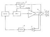
- FIG. 1is a block diagram showing an audio system according to the present invention.
- FIG. 2is a waveform showing a speaker voltage, including a back-EMF produced by the speaker after being isolated from an amplifier.
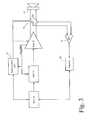
- FIG. 3is a block diagram showing portions of the audio system in greater detail.
- FIG. 4is a block diagram showing one embodiment of a classifier of the present invention.
- FIG. 5is a block diagram of another embodiment of the classifier.
- FIG. 6is a block diagram of yet another embodiment of the classifier.
- FIG. 7is a flowchart showing a preferred method of the present invention.
- an audio system 10is connected to a plurality of speakers 11 - 14 .
- Output amplifiers (i.e., power amplifiers) 15 and 16drive left and right stereo speakers from front and rear speaker sets, respectively.
- Audio system 10may be contained within a single head unit, or an output section 17 may be contained in a separate power amplifier module, for example.
- a back-EMF circuit 18is directly connected to audio system output terminals 19 for detecting back-EMF voltages to verify proper speaker interconnections as described later.
- Audio system 10includes an audio source 22 such as a radio tuner, cassette player, or compact disc player, for example.
- An audio signal from source 22is provided to the input of a digital signal processor (DSP) 21 which outputs left and right stereo signals to amplifiers 15 and 16 .
- DSPdigital signal processor
- a microcontroller unit (MCU) 20communicates with DSP 21 and source 22 to control operation of the audio system.
- MCU 20receives input commands from inputs 23 which may include push-button operator controls or an interface to a multiplex network whereby commands may be received from other locations in a vehicle.
- a display 24is connected to MCU 20 for displaying status of the audio system to allow adjustment of audio parameters, such as volume, balance, fade, tuning, and track selection.
- Amplifiers 15 and 16provide a clip detection output to back-EMF circuit 18 and to DSP 21 .
- a speakercan act as both an electromotor (i.e., the speaker moves in response to an electrical stimulus) or a generator (i.e., a voltage is generated across the voice coil impedance in response to forced motion of the speaker cone).
- the output impedance across the output of the power amplifieris so low that any electromotive force (EMF) produced by artificial movement of the speaker is greatly attenuated (i.e., short-circuited).
- EMFelectromotive force
- the present inventionemploys particular methods of causing a back-EMF and then detecting the back-EMF to classify the presence/non-presence of a speaker or even the type of speaker that is present.
- FIG. 2shows a waveform 25 representing a voltage across a speaker.
- a wave portion 26corresponds to the speaker being driven by the output amplifier.
- the excursion of the speaker cone from its rest positionfollows the magnitude of the drive signal.
- Either a low frequency signal (e.g., below about 10 Hertz) or a dc drive signalmay be employed.
- a predetermined excursione.g., a maximum excursion
- the drive signalis terminated by isolating (i.e., disconnecting) the output amplifier and/or turning off the output amplifier so that it no longer provides a low impedance path between the speaker terminals.
- the polarity of waveform 25reverses at 28 and an alternating back-EMF wave portion 30 is then produced which has a characteristic amplitude, frequency, and decay time for the particular speaker design.
- the back-EMF signal during a particular sample window 31can be detected and classified to perform the speaker detection of the present invention.
- FIG. 3shows the invention in greater detail, wherein only one speaker is shown for clarity. Isolation of the output amplifier from the output terminals of the audio system is preferably obtained using series switches 35 for selectably connecting the output terminals of the audio system (i.e., the external terminals that are connected to the vehicle wiring leading to the speakers) with either the output of amplifier 15 or the input of a signal sensing amplifier 37 .
- Amplifier 15is preferably comprised of a differential amplifier to reduce the effects of noise coupled to the speaker wires. Therefore, amplifier 37 is a difference amplifier which converts the differential (i.e., not referenced to ground) back-EMF from speaker 11 into a single-ended difference signal for processing by a classifier 38 .
- a speaker detection signal from classifier 38indicates whether a speaker is present and/or what type of speaker is currently connected to the output terminals.
- Switch control logic 36has inputs connected to MCU 20 and to the clip detect output of amplifier 15 , and has an output connected to switches 35 to control the switch conduction. During normal operation of the audio system, switch control logic 36 configures switches 35 to connect amplifier 15 to output terminals 19 .
- MCU 20indicates that the audio system is in a test mode for detecting the presence of speakers
- switch control logic 36connects amplifier 15 to terminals 19 during the drive signal so that if the speaker is properly connected then a predetermined excursion is produced. While in the test mode and after the drive signal is completed, then switch control logic 36 switches states so that difference amplifier 37 is connected to terminals 19 and amplifier 15 is isolated from output terminals 19 .
- the clip detect signalis employed to determine that a drive signal sufficient to produce maximum speaker cone excursion has been produced.
- the clip detect signalis also coupled to DSP 21 for the purpose of shutting off the drive signal at the same time that amplifier 15 is isolated from the output.
- the output from switch control logic 36may also be connected to amplifier 15 in order to turn amplifier 15 on and off.
- the output impedance of amplifier 15goes to a high state which would not attenuate the speaker back-EMF. If the response time of amplifier 15 to a turn-off signal is fast enough so that the high impedance state is reached before the speaker back-EMF signal has ceased, then it is possible in some embodiments to eliminate switches 35 and rely on the turning off of amplifier 15 to isolate it from terminals 19 .
- difference amplifier 37can be eliminated by driving one speaker terminal to a predetermined voltage (e.g., to ac ground) and not isolating that one output of the output amplifier while the other output of the output amplifier is still isolated by a switch. This results in a single-ended signal being derived from the speaker terminals which can be directly input to classifier 38 .
- a predetermined voltagee.g., to ac ground
- Classifier 38can be implemented in a number of ways. In a first embodiment shown in FIG. 4 , it is simply desired to detect the presence of a speaker without requiring the capability to distinguish between different speakers that might be connected. Thus, a level detector 40 receives the sensed speaker back-EMF signal from difference amplifier 37 and compares the detected level to a predetermined threshold 41 . The detected level will exceed the predetermined threshold only if a generator (i.e., speaker) is connected to the audio system output terminals. Level detector 40 may use any conventional level detection, such as rectifying (e.g., squaring) the incoming signal and integrating it during the predetermined sampling window.
- rectifyinge.g., squaring
- the sensed back-EMF signalcontains sufficient information to differentiate between different types or models of speakers, since differences in acoustic mass, compliance, and other factors create unique back-EMF signatures (e.g., peak amplitude, frequency, and decay rate). These signatures can be used to enable the audio system to verify the type of speaker that is present, either to signal an error if the wrong type of speaker is present or to adjust its output parameters for the type of speaker present.
- back-EMF signaturese.g., peak amplitude, frequency, and decay rate.
- FIG. 5shows one preferred embodiment for detecting the speaker type wherein the sensed back-EMF signal from difference amplifier 37 is digitized in an analog-to-digital converter 42 .
- the digitized waveformis stored in a sample random access memory (RAM) 43 .
- a Fourier transform block 44determines a frequency spectrum of the digitized waveform.
- the spectrumis comprised of several frequency ranges or bins, with each bin having a corresponding power-frequency magnitude.
- Spectra of the target speakers that were similarly binnedare compared to the measured spectrum.
- the bin magnitudesmay be weighted to improved matching accuracy.
- a binning, weighting, and matching block 45identifies the matching target speaker and sends an identifying signal to MCU 20 .
- the elements of classifier 38may be implemented within the DSP, for example.
- the sampled waveform from sample RAM 43is matched to a target speaker in the time domain.
- a pattern matching block 46matches the sampled waveform with stored time-domain templates for the target speakers using conventional pattern matching techniques.
- a speaker identification signalis provided from block 46 to MCU 20 .
- step 50the audio system enters the test mode e.g., in response to manual input of a special combination of key presses or automatically each time the audio system is turned on. Automatic testing is particularly helpful in detecting intermittent faults.
- test signal or drive signal for driving the speakers to their predetermined excursionsis output by the DSP in step 51 .
- a checkis made in step 52 to determine if the output amplifier has detected clipping of the output (i.e., the amplifier output has reached its maximum). If not, then step 52 continues to loop. Once the clip detect signal appears, the outputs of the power amplifier are isolated from the speaker terminals in step 53 .
- step 54the test signal is turned ⁇ ff and, optionally, the amplifier may also be turned off. Any back-EMF signal from the speakers are sensed in step 55 , and the sensed signals are classified in step 56 .
- the classificationmay comprise the simple comparison of the detected level of the sensed signal with a reference (to tell only if some speaker is present) or the matching of the sensed signal with predetermined signatures of a collection of target speakers (to tell which of the target speakers is actually connected).
- step 57a speaker detection signal is generated to identify whether a good speaker connection has been detected and/or the identity of the speaker that was found. If the speaker detection signal indicates the absence of a speaker, then a message may be displayed by the audio system so that corrective measures can be ttaken.
Landscapes
- Health & Medical Sciences (AREA)
- General Health & Medical Sciences (AREA)
- Otolaryngology (AREA)
- Physics & Mathematics (AREA)
- Engineering & Computer Science (AREA)
- Acoustics & Sound (AREA)
- Signal Processing (AREA)
- Circuit For Audible Band Transducer (AREA)
- Fittings On The Vehicle Exterior For Carrying Loads, And Devices For Holding Or Mounting Articles (AREA)
Abstract
Description
Claims (18)
Priority Applications (3)
| Application Number | Priority Date | Filing Date | Title |
|---|---|---|---|
| US10/195,206US6870934B2 (en) | 2002-07-15 | 2002-07-15 | Audio loudspeaker detection using back-EMF sensing |
| GB0313277AGB2390908B (en) | 2002-07-15 | 2003-06-10 | Audio loudspeaker detection using back-EMF sensing |
| DE10330903ADE10330903B4 (en) | 2002-07-15 | 2003-07-01 | Method for speaker recognition and an audio system for this purpose |
Applications Claiming Priority (1)
| Application Number | Priority Date | Filing Date | Title |
|---|---|---|---|
| US10/195,206US6870934B2 (en) | 2002-07-15 | 2002-07-15 | Audio loudspeaker detection using back-EMF sensing |
Publications (2)
| Publication Number | Publication Date |
|---|---|
| US20040008848A1 US20040008848A1 (en) | 2004-01-15 |
| US6870934B2true US6870934B2 (en) | 2005-03-22 |
Family
ID=27613007
Family Applications (1)
| Application Number | Title | Priority Date | Filing Date |
|---|---|---|---|
| US10/195,206Expired - LifetimeUS6870934B2 (en) | 2002-07-15 | 2002-07-15 | Audio loudspeaker detection using back-EMF sensing |
Country Status (3)
| Country | Link |
|---|---|
| US (1) | US6870934B2 (en) |
| DE (1) | DE10330903B4 (en) |
| GB (1) | GB2390908B (en) |
Cited By (16)
| Publication number | Priority date | Publication date | Assignee | Title |
|---|---|---|---|---|
| US20050175195A1 (en)* | 2004-02-10 | 2005-08-11 | Cheney Maynard C.Jr. | Detecting connectivity of a speaker |
| US20090274312A1 (en)* | 2008-05-02 | 2009-11-05 | Damian Howard | Detecting a Loudspeaker Configuration |
| US20090273387A1 (en)* | 2008-05-02 | 2009-11-05 | Damian Howard | Bypassing Amplification |
| US20120250894A1 (en)* | 2009-12-18 | 2012-10-04 | Gilles Bourgoin | Apparatus including means for connecting to one or more outer speakers as well as means for detecting such a connection |
| US20130170659A1 (en)* | 2010-07-09 | 2013-07-04 | St-Ericsson Sa | Speaker Impedance Measurement |
| US9247365B1 (en) | 2013-02-14 | 2016-01-26 | Google Inc. | Impedance sensing for speaker characteristic information |
| US10171912B2 (en) | 2015-07-29 | 2019-01-01 | Hewlett-Packard Development Company, L.P. | Analog device connection |
| US10555082B2 (en) | 2006-09-12 | 2020-02-04 | Sonos, Inc. | Playback device pairing |
| US10848885B2 (en) | 2006-09-12 | 2020-11-24 | Sonos, Inc. | Zone scene management |
| US20220014848A1 (en)* | 2020-07-13 | 2022-01-13 | SiliconIntervention Inc. | Method and Apparatus for Recovering Back-EMF Signal in a Switching Driver |
| US11265652B2 (en) | 2011-01-25 | 2022-03-01 | Sonos, Inc. | Playback device pairing |
| US11385858B2 (en) | 2006-09-12 | 2022-07-12 | Sonos, Inc. | Predefined multi-channel listening environment |
| US11403062B2 (en) | 2015-06-11 | 2022-08-02 | Sonos, Inc. | Multiple groupings in a playback system |
| US11429343B2 (en) | 2011-01-25 | 2022-08-30 | Sonos, Inc. | Stereo playback configuration and control |
| US11481182B2 (en) | 2016-10-17 | 2022-10-25 | Sonos, Inc. | Room association based on name |
| US12167216B2 (en) | 2006-09-12 | 2024-12-10 | Sonos, Inc. | Playback device pairing |
Families Citing this family (17)
| Publication number | Priority date | Publication date | Assignee | Title |
|---|---|---|---|---|
| JP4134755B2 (en)* | 2003-02-28 | 2008-08-20 | ヤマハ株式会社 | Speaker array drive device |
| DE102005027278B4 (en)* | 2005-06-14 | 2015-02-26 | Audi Ag | Apparatus for testing loudspeakers for operability |
| US20080304627A1 (en)* | 2007-06-07 | 2008-12-11 | Samsung Electronics Co., Ltd | Communication terminal apparatus and signal processing method thereof |
| WO2009010056A1 (en)* | 2007-07-16 | 2009-01-22 | The Tc Group A/S | Method of determining a class of a load connected to an amplifier output |
| KR101434302B1 (en) | 2007-07-25 | 2014-08-27 | 삼성전자주식회사 | Detection method of defective speaker and sound apparatus using it |
| EP2120485B1 (en)* | 2008-04-28 | 2014-10-08 | Harman Becker Automotive Systems GmbH | Load detection |
| US7911353B2 (en)* | 2008-06-02 | 2011-03-22 | Baxter International Inc. | Verifying speaker operation during alarm generation |
| US9118985B2 (en)* | 2012-12-04 | 2015-08-25 | Bose Corporation | Communication of diagnostic information from satellite to host |
| US9141187B2 (en)* | 2013-01-30 | 2015-09-22 | Panasonic Automotive Systems Company Of America, Division Of Panasonic Corporation Of North America | Interactive vehicle synthesizer |
| JP5999536B2 (en)* | 2013-08-29 | 2016-09-28 | 株式会社日立製作所 | Computer and data reading method |
| US9461606B2 (en)* | 2014-03-17 | 2016-10-04 | Adaptive Sound Technologies, Inc. | Systems and methods for automatic signal attenuation |
| FR3020232B1 (en) | 2014-04-17 | 2017-10-06 | Devialet | METHOD USING AN ACOUSTICAL ENCLOSURE COMPRISING A MODULE ADAPTED TO GENERATE A REPRESENTATIVE SIZE OF THE INTERNAL OPERATION OF THE ACOUSTICAL ENCLOSURE |
| JP6418823B2 (en)* | 2014-07-10 | 2018-11-07 | アルパイン株式会社 | Speaker diagnosis apparatus and speaker diagnosis method |
| US9374052B1 (en)* | 2014-11-27 | 2016-06-21 | Blackberry Limited | Voice coil protection using damping |
| US10554683B1 (en) | 2016-05-19 | 2020-02-04 | Board Of Trustees Of The University Of Alabama, For And On Behalf Of The University Of Alabama In Huntsville | Systems and methods for preventing remote attacks against transportation systems |
| CN106921930A (en)* | 2017-04-17 | 2017-07-04 | 苏州美声电子有限公司 | Audio amplifier production line efficiency monitoring system |
| US12192710B2 (en)* | 2022-08-01 | 2025-01-07 | Crestron Electronics, Inc. | System and method for verifying connection between an active loudspeaker assembly and a passive loudspeaker assembly |
Citations (5)
| Publication number | Priority date | Publication date | Assignee | Title |
|---|---|---|---|---|
| US5042070A (en) | 1990-10-01 | 1991-08-20 | Ford Motor Company | Automatically configured audio system |
| US5361305A (en) | 1993-11-12 | 1994-11-01 | Delco Electronics Corporation | Automated system and method for automotive audio test |
| US5450624A (en) | 1993-01-07 | 1995-09-12 | Ford Motor Company | Method and apparatus for diagnosing amp to speaker connections |
| EP0841570A2 (en) | 1996-11-08 | 1998-05-13 | Ford Motor Company | Automatic detection of shorted loudspeakers in automotive audio systems |
| JPH11146496A (en) | 1997-11-05 | 1999-05-28 | Fujitsu Ten Ltd | Method and device for speaker abnormality detection |
Family Cites Families (2)
| Publication number | Priority date | Publication date | Assignee | Title |
|---|---|---|---|---|
| US5420624A (en)* | 1992-02-24 | 1995-05-30 | Videojet Systems International, Inc. | Method and apparatus for correcting printing distortions in an ink jet printer |
| DE19544658C1 (en)* | 1995-11-30 | 1997-03-20 | Bosch Gmbh Robert | Loudspeaker impedance testing method |
- 2002
- 2002-07-15USUS10/195,206patent/US6870934B2/ennot_activeExpired - Lifetime
- 2003
- 2003-06-10GBGB0313277Apatent/GB2390908B/ennot_activeExpired - Fee Related
- 2003-07-01DEDE10330903Apatent/DE10330903B4/ennot_activeExpired - Fee Related
Patent Citations (6)
| Publication number | Priority date | Publication date | Assignee | Title |
|---|---|---|---|---|
| US5042070A (en) | 1990-10-01 | 1991-08-20 | Ford Motor Company | Automatically configured audio system |
| US5450624A (en) | 1993-01-07 | 1995-09-12 | Ford Motor Company | Method and apparatus for diagnosing amp to speaker connections |
| US5361305A (en) | 1993-11-12 | 1994-11-01 | Delco Electronics Corporation | Automated system and method for automotive audio test |
| EP0841570A2 (en) | 1996-11-08 | 1998-05-13 | Ford Motor Company | Automatic detection of shorted loudspeakers in automotive audio systems |
| US5815584A (en) | 1996-11-08 | 1998-09-29 | Ford Motor Company | Automatic detection of shorted loudspeakers in automotive audio systems |
| JPH11146496A (en) | 1997-11-05 | 1999-05-28 | Fujitsu Ten Ltd | Method and device for speaker abnormality detection |
Cited By (33)
| Publication number | Priority date | Publication date | Assignee | Title |
|---|---|---|---|---|
| US20050175195A1 (en)* | 2004-02-10 | 2005-08-11 | Cheney Maynard C.Jr. | Detecting connectivity of a speaker |
| US10848885B2 (en) | 2006-09-12 | 2020-11-24 | Sonos, Inc. | Zone scene management |
| US10555082B2 (en) | 2006-09-12 | 2020-02-04 | Sonos, Inc. | Playback device pairing |
| US11385858B2 (en) | 2006-09-12 | 2022-07-12 | Sonos, Inc. | Predefined multi-channel listening environment |
| US11082770B2 (en) | 2006-09-12 | 2021-08-03 | Sonos, Inc. | Multi-channel pairing in a media system |
| US10966025B2 (en) | 2006-09-12 | 2021-03-30 | Sonos, Inc. | Playback device pairing |
| US12219328B2 (en) | 2006-09-12 | 2025-02-04 | Sonos, Inc. | Zone scene activation |
| US10897679B2 (en) | 2006-09-12 | 2021-01-19 | Sonos, Inc. | Zone scene management |
| US11540050B2 (en) | 2006-09-12 | 2022-12-27 | Sonos, Inc. | Playback device pairing |
| US12167216B2 (en) | 2006-09-12 | 2024-12-10 | Sonos, Inc. | Playback device pairing |
| US11388532B2 (en) | 2006-09-12 | 2022-07-12 | Sonos, Inc. | Zone scene activation |
| US20090274312A1 (en)* | 2008-05-02 | 2009-11-05 | Damian Howard | Detecting a Loudspeaker Configuration |
| US20090273387A1 (en)* | 2008-05-02 | 2009-11-05 | Damian Howard | Bypassing Amplification |
| US8325931B2 (en) | 2008-05-02 | 2012-12-04 | Bose Corporation | Detecting a loudspeaker configuration |
| US8063698B2 (en) | 2008-05-02 | 2011-11-22 | Bose Corporation | Bypassing amplification |
| US9131306B2 (en)* | 2009-12-18 | 2015-09-08 | Sagemcom Broadband Sas | Apparatus including means for connecting to one or more outer speakers as well as means for detecting such a connection |
| US20120250894A1 (en)* | 2009-12-18 | 2012-10-04 | Gilles Bourgoin | Apparatus including means for connecting to one or more outer speakers as well as means for detecting such a connection |
| US9237406B2 (en)* | 2010-07-09 | 2016-01-12 | St-Ericsson Sa | Speaker impedance measurement |
| US20130170659A1 (en)* | 2010-07-09 | 2013-07-04 | St-Ericsson Sa | Speaker Impedance Measurement |
| US11758327B2 (en) | 2011-01-25 | 2023-09-12 | Sonos, Inc. | Playback device pairing |
| US12248732B2 (en) | 2011-01-25 | 2025-03-11 | Sonos, Inc. | Playback device configuration and control |
| US11429343B2 (en) | 2011-01-25 | 2022-08-30 | Sonos, Inc. | Stereo playback configuration and control |
| US11265652B2 (en) | 2011-01-25 | 2022-03-01 | Sonos, Inc. | Playback device pairing |
| US9247365B1 (en) | 2013-02-14 | 2016-01-26 | Google Inc. | Impedance sensing for speaker characteristic information |
| US12026431B2 (en) | 2015-06-11 | 2024-07-02 | Sonos, Inc. | Multiple groupings in a playback system |
| US11403062B2 (en) | 2015-06-11 | 2022-08-02 | Sonos, Inc. | Multiple groupings in a playback system |
| US10171912B2 (en) | 2015-07-29 | 2019-01-01 | Hewlett-Packard Development Company, L.P. | Analog device connection |
| US11481182B2 (en) | 2016-10-17 | 2022-10-25 | Sonos, Inc. | Room association based on name |
| US12242769B2 (en) | 2016-10-17 | 2025-03-04 | Sonos, Inc. | Room association based on name |
| US11750970B2 (en)* | 2020-07-13 | 2023-09-05 | SiliconIntervention Inc. | Method and apparatus for recovering back-EMF signal in a switching driver |
| TWI856260B (en)* | 2020-07-13 | 2024-09-21 | 加拿大商矽介入公司 | Method and apparatus for recovering back-emf signal in a switching driver |
| US20220014848A1 (en)* | 2020-07-13 | 2022-01-13 | SiliconIntervention Inc. | Method and Apparatus for Recovering Back-EMF Signal in a Switching Driver |
| WO2022011459A1 (en)* | 2020-07-13 | 2022-01-20 | SiliconIntervention Inc. | Method and apparatus for recovering back-emf signal in a switching driver |
Also Published As
| Publication number | Publication date |
|---|---|
| DE10330903A1 (en) | 2004-02-12 |
| GB2390908B (en) | 2004-06-16 |
| DE10330903B4 (en) | 2005-06-16 |
| US20040008848A1 (en) | 2004-01-15 |
| GB2390908A (en) | 2004-01-21 |
| GB0313277D0 (en) | 2003-07-16 |
Similar Documents
| Publication | Publication Date | Title |
|---|---|---|
| US6870934B2 (en) | Audio loudspeaker detection using back-EMF sensing | |
| EP2120485B1 (en) | Load detection | |
| Ratnam et al. | Blind estimation of reverberation time | |
| US8311233B2 (en) | Position sensing using loudspeakers as microphones | |
| CA2483609C (en) | Sound detection and localization system | |
| US7869611B2 (en) | Test tone determination method and sound field correction apparatus | |
| US8175303B2 (en) | Electronic apparatus for vehicle, and method and system for optimally correcting sound field in vehicle | |
| US9100760B2 (en) | Audio channel fault detection system | |
| CN101513085A (en) | Identification method and apparatus in audio system | |
| CN1227949C (en) | Loudspeak polarity judging circuit and audio circuit with function of polarity judging and switching | |
| EP2277328A2 (en) | Detecting a loudspeaker configuration | |
| CN103414990B (en) | Indoor sound reinforcement device detection method | |
| CN110044472A (en) | Product abnormal sound abnormal sound intelligent checking system on a kind of line | |
| US6538570B1 (en) | Glass-break detector and method of alarm discrimination | |
| CN103414991A (en) | Self-adaptive adjustment method for indoor sound reinforcement system | |
| KR20060047291A (en) | Measuring device, measuring method, recording medium | |
| CN105872205A (en) | Information processing method and device | |
| CN106775558B (en) | Method and device for obtaining earphone optimization parameters and audio providing method and system | |
| US9041412B2 (en) | Methods of testing a connection between speakers and a power amplifier and devices therefor | |
| US20060050891A1 (en) | Method for automatic loudspeaker polarity determination through loudspeaker-room acoustic responses | |
| CN112017636A (en) | Vehicle-based user pronunciation simulation method, system, device and storage medium | |
| CN109658955A (en) | Sonic boom detection method and device | |
| US20230093913A1 (en) | Apparatus for locally recognizing an instruction of a given instruction set | |
| CN112770244B (en) | Method and device for detecting line fault of loudspeaker and audio playing equipment | |
| JP3473803B2 (en) | Speaker inspection equipment |
Legal Events
| Date | Code | Title | Description |
|---|---|---|---|
| AS | Assignment | Owner name:VISTEON GLOBAL TECHNOLOGIES, INC., MICHIGAN Free format text:ASSIGNMENT OF ASSIGNORS INTEREST;ASSIGNORS:KROCHMAL, ANDREW C.;WHITECAR, JOHN E.;CADENA, ROBERT K.;AND OTHERS;REEL/FRAME:013120/0978;SIGNING DATES FROM 20020709 TO 20020711 | |
| STCF | Information on status: patent grant | Free format text:PATENTED CASE | |
| AS | Assignment | Owner name:JPMORGAN CHASE BANK, N.A., AS ADMINISTRATIVE AGENT Free format text:SECURITY AGREEMENT;ASSIGNOR:VISTEON GLOBAL TECHNOLOGIES, INC.;REEL/FRAME:020497/0733 Effective date:20060613 | |
| FPAY | Fee payment | Year of fee payment:4 | |
| AS | Assignment | Owner name:JPMORGAN CHASE BANK, TEXAS Free format text:SECURITY INTEREST;ASSIGNOR:VISTEON GLOBAL TECHNOLOGIES, INC.;REEL/FRAME:022368/0001 Effective date:20060814 Owner name:JPMORGAN CHASE BANK,TEXAS Free format text:SECURITY INTEREST;ASSIGNOR:VISTEON GLOBAL TECHNOLOGIES, INC.;REEL/FRAME:022368/0001 Effective date:20060814 | |
| AS | Assignment | Owner name:WILMINGTON TRUST FSB, AS ADMINISTRATIVE AGENT, MIN Free format text:ASSIGNMENT OF SECURITY INTEREST IN PATENTS;ASSIGNOR:JPMORGAN CHASE BANK, N.A., AS ADMINISTRATIVE AGENT;REEL/FRAME:022575/0186 Effective date:20090415 Owner name:WILMINGTON TRUST FSB, AS ADMINISTRATIVE AGENT,MINN Free format text:ASSIGNMENT OF SECURITY INTEREST IN PATENTS;ASSIGNOR:JPMORGAN CHASE BANK, N.A., AS ADMINISTRATIVE AGENT;REEL/FRAME:022575/0186 Effective date:20090415 | |
| AS | Assignment | Owner name:THE BANK OF NEW YORK MELLON, AS ADMINISTRATIVE AGE Free format text:ASSIGNMENT OF PATENT SECURITY INTEREST;ASSIGNOR:JPMORGAN CHASE BANK, N.A., A NATIONAL BANKING ASSOCIATION;REEL/FRAME:022974/0057 Effective date:20090715 | |
| AS | Assignment | Owner name:VISTEON GLOBAL TECHNOLOGIES, INC., MICHIGAN Free format text:RELEASE BY SECURED PARTY AGAINST SECURITY INTEREST IN PATENTS RECORDED AT REEL 022974 FRAME 0057;ASSIGNOR:THE BANK OF NEW YORK MELLON;REEL/FRAME:025095/0711 Effective date:20101001 | |
| AS | Assignment | Owner name:VISTEON GLOBAL TECHNOLOGIES, INC., MICHIGAN Free format text:RELEASE BY SECURED PARTY AGAINST SECURITY INTEREST IN PATENTS RECORDED AT REEL 022575 FRAME 0186;ASSIGNOR:WILMINGTON TRUST FSB, AS ADMINISTRATIVE AGENT;REEL/FRAME:025105/0201 Effective date:20101001 | |
| AS | Assignment | Owner name:MORGAN STANLEY SENIOR FUNDING, INC., AS AGENT, NEW Free format text:SECURITY AGREEMENT;ASSIGNORS:VISTEON CORPORATION;VC AVIATION SERVICES, LLC;VISTEON ELECTRONICS CORPORATION;AND OTHERS;REEL/FRAME:025241/0317 Effective date:20101007 Owner name:MORGAN STANLEY SENIOR FUNDING, INC., AS AGENT, NEW Free format text:SECURITY AGREEMENT (REVOLVER);ASSIGNORS:VISTEON CORPORATION;VC AVIATION SERVICES, LLC;VISTEON ELECTRONICS CORPORATION;AND OTHERS;REEL/FRAME:025238/0298 Effective date:20101001 | |
| AS | Assignment | Owner name:VISTEON CORPORATION, MICHIGAN Free format text:RELEASE BY SECURED PARTY AGAINST SECURITY INTEREST IN PATENTS ON REEL 025241 FRAME 0317;ASSIGNOR:MORGAN STANLEY SENIOR FUNDING, INC.;REEL/FRAME:026178/0412 Effective date:20110406 Owner name:VISTEON INTERNATIONAL HOLDINGS, INC., MICHIGAN Free format text:RELEASE BY SECURED PARTY AGAINST SECURITY INTEREST IN PATENTS ON REEL 025241 FRAME 0317;ASSIGNOR:MORGAN STANLEY SENIOR FUNDING, INC.;REEL/FRAME:026178/0412 Effective date:20110406 Owner name:VC AVIATION SERVICES, LLC, MICHIGAN Free format text:RELEASE BY SECURED PARTY AGAINST SECURITY INTEREST IN PATENTS ON REEL 025241 FRAME 0317;ASSIGNOR:MORGAN STANLEY SENIOR FUNDING, INC.;REEL/FRAME:026178/0412 Effective date:20110406 Owner name:VISTEON SYSTEMS, LLC, MICHIGAN Free format text:RELEASE BY SECURED PARTY AGAINST SECURITY INTEREST IN PATENTS ON REEL 025241 FRAME 0317;ASSIGNOR:MORGAN STANLEY SENIOR FUNDING, INC.;REEL/FRAME:026178/0412 Effective date:20110406 Owner name:VISTEON INTERNATIONAL BUSINESS DEVELOPMENT, INC., Free format text:RELEASE BY SECURED PARTY AGAINST SECURITY INTEREST IN PATENTS ON REEL 025241 FRAME 0317;ASSIGNOR:MORGAN STANLEY SENIOR FUNDING, INC.;REEL/FRAME:026178/0412 Effective date:20110406 Owner name:VISTEON ELECTRONICS CORPORATION, MICHIGAN Free format text:RELEASE BY SECURED PARTY AGAINST SECURITY INTEREST IN PATENTS ON REEL 025241 FRAME 0317;ASSIGNOR:MORGAN STANLEY SENIOR FUNDING, INC.;REEL/FRAME:026178/0412 Effective date:20110406 Owner name:VISTEON GLOBAL TREASURY, INC., MICHIGAN Free format text:RELEASE BY SECURED PARTY AGAINST SECURITY INTEREST IN PATENTS ON REEL 025241 FRAME 0317;ASSIGNOR:MORGAN STANLEY SENIOR FUNDING, INC.;REEL/FRAME:026178/0412 Effective date:20110406 Owner name:VISTEON GLOBAL TECHNOLOGIES, INC., MICHIGAN Free format text:RELEASE BY SECURED PARTY AGAINST SECURITY INTEREST IN PATENTS ON REEL 025241 FRAME 0317;ASSIGNOR:MORGAN STANLEY SENIOR FUNDING, INC.;REEL/FRAME:026178/0412 Effective date:20110406 Owner name:VISTEON EUROPEAN HOLDING, INC., MICHIGAN Free format text:RELEASE BY SECURED PARTY AGAINST SECURITY INTEREST IN PATENTS ON REEL 025241 FRAME 0317;ASSIGNOR:MORGAN STANLEY SENIOR FUNDING, INC.;REEL/FRAME:026178/0412 Effective date:20110406 | |
| FPAY | Fee payment | Year of fee payment:8 | |
| AS | Assignment | Owner name:CITIBANK., N.A., AS ADMINISTRATIVE AGENT, NEW YORK Free format text:SECURITY INTEREST;ASSIGNORS:VISTEON CORPORATION, AS GRANTOR;VISTEON GLOBAL TECHNOLOGIES, INC., AS GRANTOR;REEL/FRAME:032713/0065 Effective date:20140409 | |
| AS | Assignment | Owner name:VISTEON EUROPEAN HOLDINGS, INC., MICHIGAN Free format text:RELEASE OF SECURITY INTEREST IN INTELLECTUAL PROPERTY;ASSIGNOR:MORGAN STANLEY SENIOR FUNDING, INC.;REEL/FRAME:033107/0717 Effective date:20140409 Owner name:VISTEON GLOBAL TECHNOLOGIES, INC., MICHIGAN Free format text:RELEASE OF SECURITY INTEREST IN INTELLECTUAL PROPERTY;ASSIGNOR:MORGAN STANLEY SENIOR FUNDING, INC.;REEL/FRAME:033107/0717 Effective date:20140409 Owner name:VISTEON GLOBAL TREASURY, INC., MICHIGAN Free format text:RELEASE OF SECURITY INTEREST IN INTELLECTUAL PROPERTY;ASSIGNOR:MORGAN STANLEY SENIOR FUNDING, INC.;REEL/FRAME:033107/0717 Effective date:20140409 Owner name:VISTEON ELECTRONICS CORPORATION, MICHIGAN Free format text:RELEASE OF SECURITY INTEREST IN INTELLECTUAL PROPERTY;ASSIGNOR:MORGAN STANLEY SENIOR FUNDING, INC.;REEL/FRAME:033107/0717 Effective date:20140409 Owner name:VISTEON SYSTEMS, LLC, MICHIGAN Free format text:RELEASE OF SECURITY INTEREST IN INTELLECTUAL PROPERTY;ASSIGNOR:MORGAN STANLEY SENIOR FUNDING, INC.;REEL/FRAME:033107/0717 Effective date:20140409 Owner name:VISTEON INTERNATIONAL BUSINESS DEVELOPMENT, INC., Free format text:RELEASE OF SECURITY INTEREST IN INTELLECTUAL PROPERTY;ASSIGNOR:MORGAN STANLEY SENIOR FUNDING, INC.;REEL/FRAME:033107/0717 Effective date:20140409 Owner name:VISTEON CORPORATION, MICHIGAN Free format text:RELEASE OF SECURITY INTEREST IN INTELLECTUAL PROPERTY;ASSIGNOR:MORGAN STANLEY SENIOR FUNDING, INC.;REEL/FRAME:033107/0717 Effective date:20140409 Owner name:VISTEON INTERNATIONAL HOLDINGS, INC., MICHIGAN Free format text:RELEASE OF SECURITY INTEREST IN INTELLECTUAL PROPERTY;ASSIGNOR:MORGAN STANLEY SENIOR FUNDING, INC.;REEL/FRAME:033107/0717 Effective date:20140409 Owner name:VC AVIATION SERVICES, LLC, MICHIGAN Free format text:RELEASE OF SECURITY INTEREST IN INTELLECTUAL PROPERTY;ASSIGNOR:MORGAN STANLEY SENIOR FUNDING, INC.;REEL/FRAME:033107/0717 Effective date:20140409 | |
| FPAY | Fee payment | Year of fee payment:12 |